EP2456284A1 - Complex microwave range - Google Patents
Complex microwave range Download PDFInfo
- Publication number
- EP2456284A1 EP2456284A1 EP20110183377 EP11183377A EP2456284A1 EP 2456284 A1 EP2456284 A1 EP 2456284A1 EP 20110183377 EP20110183377 EP 20110183377 EP 11183377 A EP11183377 A EP 11183377A EP 2456284 A1 EP2456284 A1 EP 2456284A1
- Authority
- EP
- European Patent Office
- Prior art keywords
- tray
- microwave range
- cooking chamber
- heating device
- food
- Prior art date
- Legal status (The legal status is an assumption and is not a legal conclusion. Google has not performed a legal analysis and makes no representation as to the accuracy of the status listed.)
- Granted
Links
- 238000010411 cooking Methods 0.000 claims abstract description 96
- 238000010438 heat treatment Methods 0.000 claims abstract description 59
- 229910052751 metal Inorganic materials 0.000 claims description 12
- 239000002184 metal Substances 0.000 claims description 12
- 230000005855 radiation Effects 0.000 claims description 8
- 239000000463 material Substances 0.000 claims description 6
- 239000000919 ceramic Substances 0.000 claims description 4
- 239000011521 glass Substances 0.000 claims description 4
- 239000002990 reinforced plastic Substances 0.000 claims description 4
- 230000004308 accommodation Effects 0.000 description 7
- 238000000034 method Methods 0.000 description 4
- 230000005684 electric field Effects 0.000 description 2
- 238000002844 melting Methods 0.000 description 2
- 230000008018 melting Effects 0.000 description 2
- 239000000956 alloy Substances 0.000 description 1
- 229910045601 alloy Inorganic materials 0.000 description 1
- 229910052782 aluminium Inorganic materials 0.000 description 1
- XAGFODPZIPBFFR-UHFFFAOYSA-N aluminium Chemical compound [Al] XAGFODPZIPBFFR-UHFFFAOYSA-N 0.000 description 1
- 238000007664 blowing Methods 0.000 description 1
- 239000011810 insulating material Substances 0.000 description 1
- 230000007257 malfunction Effects 0.000 description 1
Images


Classifications
-
- H—ELECTRICITY
- H05—ELECTRIC TECHNIQUES NOT OTHERWISE PROVIDED FOR
- H05B—ELECTRIC HEATING; ELECTRIC LIGHT SOURCES NOT OTHERWISE PROVIDED FOR; CIRCUIT ARRANGEMENTS FOR ELECTRIC LIGHT SOURCES, IN GENERAL
- H05B6/00—Heating by electric, magnetic or electromagnetic fields
- H05B6/64—Heating using microwaves
- H05B6/647—Aspects related to microwave heating combined with other heating techniques
- H05B6/6482—Aspects related to microwave heating combined with other heating techniques combined with radiant heating, e.g. infrared heating
-
- H—ELECTRICITY
- H05—ELECTRIC TECHNIQUES NOT OTHERWISE PROVIDED FOR
- H05B—ELECTRIC HEATING; ELECTRIC LIGHT SOURCES NOT OTHERWISE PROVIDED FOR; CIRCUIT ARRANGEMENTS FOR ELECTRIC LIGHT SOURCES, IN GENERAL
- H05B6/00—Heating by electric, magnetic or electromagnetic fields
- H05B6/64—Heating using microwaves
- H05B6/6408—Supports or covers specially adapted for use in microwave heating apparatus
Definitions
- Embodiments of the present invention relate to a complex microwave range which has an oven function and is provided with a tray unit on which an object to be heated is placed.
- a microwave range is an apparatus which supplies microwaves to the inside of a cooking chamber to cook an object to be heated.
- Such a microwave range having the oven function is designed such that heat of a heater is used so as to implement a wider variety of heating methods and heating conditions than a heating method using microwaves alone.
- trays having different materials and installed within the cooking chamber of the microwave range need to be differently selected according to heating methods, i.e., cooking methods of an object to be cooked.
- a microwave range tray is used during heating using microwaves, and an oven tray is used during heating using the heater.
- a complex microwave range includes a main body provided with a cooking chamber, a first heating device provided with a magnetron supplying high frequency waves to the inside of the cooking chamber, a second heating device supplying heat to the cooking chamber to heat food to be cooked within the cooking chamber, tray hanger parts provided on side walls of the cooking chamber and formed of a metal, a first tray hung on and supported by the tray hanger parts and formed of an electromagnetic wave transmitting material, and a second tray not supported by the tray hanger parts, mounted on the upper surface of the first tray and formed of a thermally conductive metal.
- the second tray may have a smaller size than that of the first tray.
- the first tray may be formed of one of ceramic, glass and reinforced plastic.
- the first tray may include a cooking table having a recess shape on which the food to be cooked is placed, and a bent part bent from the edge of the cooking table so as to be hung on and supported by the tray hanger parts.
- the second tray may have a shape corresponding to the shape of the cooking table so as to be mounted on the cooking table, and be separable from the first tray.
- Gripping parts enabling a user to grip the second tray may be provided on the second tray.
- the second heating device may include a radiation heating device applying radiant heat directly to the food to be cooked so as to cook the food.
- the radiation heating device may include an upper grill heater provided at the upper portion of the cooking chamber and a lower grill heater provided at the lower portion of the cooking chamber.
- the second heating device may include a convection heater to generate heat, and a convection circulation fan to circulate air heated by the convection heater to the inside of the cooking chamber.
- the second heating device may be disposed on the inner surface of one side wall of the cooking chamber.
- a complex microwave range which performs high-frequency type heating and heating using a separate heater with respect to food to be cooked within a cooking chamber, includes tray hanger parts provided on both side walls of the cooking chamber and formed of a metal, a microwave range tray, on which the food to be cooked is placed, hung on and supported by the tray hanger parts so as to be used during high-frequency type heating, and an oven tray used during heating using the heater, wherein the oven tray has a smaller size than that of the microwave range tray so that the oven tray is not supported by the tray hanger parts, and is separably mounted on the upper surface of the microwave range tray.
- the microwave range tray may be formed of one of ceramic, glass and reinforced plastic so as to transmit electromagnetic waves, and the oven tray may be formed of a thermally conductive metal.
- the food may be cooked under the condition that only the microwave range tray is supported by the tray hanger parts of the cooking chamber during high-frequency type heating, and the food may be cooked under the condition that the oven tray is mounted on the upper surface of the microwave range tray during heating using the heater.
- the microwave range tray may include a cooking table having a recess shape on which the food to be cooked is placed, and a bent part bent from the edge of the cooking table so as to be hung on and supported by the tray hanger parts, and the oven tray may have a shape corresponding to the shape of the cooking table so as to be mounted on the cooking table.
- the heater may include grill heaters respectively disposed at the upper and lower portions of the cooking chamber so as to apply radiant heat directly to the food to be cooked.
- the heater may include a convection heater to heat air discharged by a convection circulation fan provided to forcibly convect hot air within the cooking chamber.
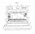
- FIG. 1 is a perspective view schematically illustrating the internal structure of a complex microwave range in accordance with one embodiment of the present invention
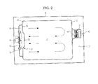
- FIG. 2 is a cross-sectional view of the complex microwave range in accordance with the embodiment of the present invention.
- the complex microwave range in accordance with this embodiment includes a main body 10 forming the external appearance of the microwave range, a cooking chamber 11 provided within the main body 10 such that food to be cooked is placed in the cooking chamber 11, and a door 20 installed on the front surface of the main body 10 so as to open and close the cooking chamber 11.
- a control panel 30 to adjust various conditions, such as output and cooking time of the microwave range, may be provided at one side of the front surface of the main body 10.
- the control panel 30 includes a key input unit 31 to set and receive various conditions, such as adjustment of output of the microwave range, a cooking function and start and cancellation of operation of the microwave range, and a display 33 to display the set conditions and an operating state of the microwave range thereby by various characters, figures and signs.
- An insulating material (not shown) is installed between the main body 10 and the cooking chamber 11 so as to surround the cooking chamber 11, a convection heating device 50 circulating heat to transfer the heat to the inside of the cooking chamber 11 is provided on one side wall 12 of the cooking chamber 11, and a high-frequency heating device 60 using a magnetron 61 is installed on the other side wall 13 of the cooking chamber 11.
- the convection heating device 50 includes a convection heater 51 generating heat to generate hot air to cook food, and a convection circulation fan 53 circulating air around the convection heater 5 to generate convection.
- the convection circulation fan 53 is installed within a fan accommodation part 14 hollowed on the side wall 12 of the cooking chamber 11 to a designated depth, and a motor 54 to drive the convection circulation fan 53 is installed at the rear of the fan accommodation part 14.
- a fan cover 57 to divide the cooking chamber 11 and the fan accommodation part 14 from each other is installed in front of the fan accommodation part 14, a plurality of inlets 58 through which air within the cooking chamber 11 is introduced into the fan accommodation part 14 is provided at the center of the fan cover 57, and a plurality of outlets 59 through which air within the fan accommodation part 14 is discharged to the cooking chamber 11 by the convection circulation fan 53 is provided at the outside of the plurality of inlets 58.
- Such a convection circulation fan 53 performs a function of circulating hot air within the cooking chamber 11.
- the convection circulation fan 53 may be a centrifugal fan which inhales air in the axial direction and blows air in the radial direction, and the convection heater 51 may be disposed around the circumference of the convection circulation fan 53 so as to heat air blown by the convection circulation fan 53.
- a radiation heating device 70 to apply radiant heat to food to be cooked so as to cook the food may be provided at the upper and lower portions of the cooking chamber 11.
- the radiation heating device 70 includes an upper grill heater 71 provided at the upper portion of the cooking chamber 11, and a lower grill heater 73 provided at the lower portion of the cooking chamber 11.
- the upper and lower grill heaters 71 and 73 are respectively accommodated within grill heater accommodation parts 15 provided at the upper and lower portions of the cooking chamber 11, thereby heating upper and lower portions of the food.
- the high-frequency heating device 60 includes a magnetron 61 disposed within a machine room 17 provided within the side wall 13 of the cooking chamber 11 to supply high frequency waves, and a high-voltage transformer (not shown) to apply high voltage to the magnetron 61.
- the high frequency waves irradiated from the magnetron 61 are irradiated to the inside of the cooking chamber 11 through high-frequency outlets 63 formed on the side wall 13 of the cooking chamber 11, thereby cooking food.
- Various heat sources i.e., a steam heating device, etc.
- a steam heating device i.e., a thermoelectric heating device, etc.
- the high-frequency heating device 60 and any one of other heating devices may be combined.
- operation to cook food through the high-frequency heating device 60 is referred to as a microwave range mode
- operation to cook food through other heating devices is referred to as an oven mode.
- Tray hanger parts 40 formed of a metal and protruded such that a tray unit 80 on which food is placed is hung on the tray hanger parts 40 may be provided on both side walls 12 and 13 of the cooking chamber 11.
- the plural tray hanger parts 40 are separated from each other in the vertical direction so as to adjust the height of the tray unit 80, as needed.
- FIG. 3 is an exploded perspective view illustrating the tray unit in accordance with the embodiment of the present invention.
- the tray unit 80 in accordance with the embodiment of the present invention includes a microwave range tray (hereinafter, referred to as a first tray) 81 used during heating through high frequency waves, and a an oven tray (hereinafter, referred to as a second tray) 85 used during heating through a separate motor, so as to be properly used in the complex microwave range performing both heating through the high frequency waves and heating through the separate motor.
- a microwave range tray hereinafter, referred to as a first tray
- a second tray used during heating through a separate motor
- the first tray 81 may be formed of an electromagnetic wave transmitting material so as to transmit electromagnetic waves oscillated by the high-frequency heating device 60.
- Such a first tray 81 may be formed of one of ceramic, glass and reinforced plastic.
- first ray 81 may have a sufficient size to be hung on and supported by the tray hanger parts 40 provided on both side walls 12 and 13 of the cooking chamber 11.
- the first tray 81 includes a cooking table 82 on which food to be cooked is placed, and a bent part 83 bent from the edge of the cooking table 82 so as to be hung on and supported by the tray hanger parts 40.
- the cooking table 82 has a recess shape hollowed to a designated depth so as to accommodate the food to be cooked.
- the first tray 81 formed of the electromagnetic wave transmitting material is hung on and supported by the tray hanger parts 40 formed of the metal, melting of the edge of the first tray 81 and spark generation due to an electric field formed between the first tray 81 and the tray hanger parts 40 caused by the electromagnetic wave generated by the high-frequency heating device 60 may be prevented.
- the second tray 85 is formed of a metal having excellent thermal conductivity, such as aluminum or an alloy thereof, and has a smaller size than the first tray 81.
- Such a second tray 85 has a small size so as not to be hung on and supported by the tray hanger parts 40 formed on both side walls 12 and 13 of the cooking chamber 11, and thus is provided not to be independently used within the cooking chamber 11.
- the second tray 85 is formed of a metal having excellent thermal conductivity so as to uniformly supply heat to food to be cooked placed on the second tray 85 when the food is cooked using a heat source, i.e., the convection heating device 50 or the radiation heating device 70, other than the high-frequency heating device 60, thereby solving problems caused by spark generation due to contact between the second tray 85 and the tray hanger parts 40 formed of the metal.
- a heat source i.e., the convection heating device 50 or the radiation heating device 70, other than the high-frequency heating device 60
- the second tray 85 may have a shape corresponding to the shape of the cooking table 82 so as to be mounted on the hollowed cooking table 82.
- gripping parts 86 enabling a user to grip the second tray 85 when the second tray 85 is separated from the cooking table 82 of the first tray 81 may be formed at both sides of the edge of the second tray 85.
- FIG. 4 illustrates the complex microwave range in accordance with the embodiment of the present invention in a state in which a tray used in a microwave range mode is mounted within the cooking chamber.
- the user places food on the first tray 81, opens the door 20, and then hangs the first tray 81 on the tray hanger parts 40 provided on both side walls 12 and 13 of the cooking chamber 11.
- the user may confuse the tray used in the oven mode and the tray used in the microwave range mode with each other.
- the second tray 85 is not hung on the tray hanger parts 40 of the cooking chamber 11, and thus, when the complex microwave range is operated in the microwave range mode, misuse of the tray used in the oven mode may be prevented.
- the user closes the door 20 so as to seal the cooking chamber 11, and then sets the microwave range mode through the control panel 30, thereby operating the complex microwave range in the microwave range mode.
- the user mounts the second tray 85 on the cooking table 82 of the first tray 81, places food to be cooked on the upper surface of the second tray 85, and then inserts the tray unit including the first tray 81 and the second tray 85 into the cooking chamber 11 (with reference to FIG. 1 ).
- the user closes the door 20 so as to seal the cooking chamber 11, and then sets the oven mode through the control panel 30, thereby operating the complex microwave range in the oven mode.
- Air heated by the convection heater 51 is discharged to the inside of the cooking chamber 11 through the outlets 59 by blowing force of the convection circulation fan 53.
- the hot air discharged to the inside of the cooking chamber 11 heats the food placed on the second tray 85, and is then inhaled to the convection circulation fan 53 through the inlets 58. In such a manner, air within the cooking chamber 11 is forcibly convected by the convection circulation fan 53.
- the radiation heating device 70 may be operated to heat the inside of the cooking chamber through radiant heat, and the air within the cooking chamber 11 may be forcibly convected by the convection circulation fan 53.
- Such heat within the cooking chamber 11 is conducted through the second tray 85 and is uniformly transferred to the lower end of the food placed on the second tray 85, thereby uniformly cooking the food.
- a complex microwave range in accordance with one embodiment of the present invention may prevent damage due to misuse of a tray in the microwave range mode.
Abstract
Description
- Embodiments of the present invention relate to a complex microwave range which has an oven function and is provided with a tray unit on which an object to be heated is placed.
- In general, a microwave range is an apparatus which supplies microwaves to the inside of a cooking chamber to cook an object to be heated.
- Recently, a microwave range provided with a heater as another heating source to have an oven function has been provided.
- Such a microwave range having the oven function is designed such that heat of a heater is used so as to implement a wider variety of heating methods and heating conditions than a heating method using microwaves alone.
- In case of the above microwave range implementing heating through such two ways, trays having different materials and installed within the cooking chamber of the microwave range need to be differently selected according to heating methods, i.e., cooking methods of an object to be cooked.
- That is, a microwave range tray is used during heating using microwaves, and an oven tray is used during heating using the heater.
- Therefore, it is an aspect of the present invention to provide a tray unit suited to a microwave range having an oven function.
- Additional aspects of the invention will be set forth in part in the description which follows and, in part, will be obvious from the description, or may be learned by practice of the invention.
- In accordance with one aspect of the present invention, a complex microwave range includes a main body provided with a cooking chamber, a first heating device provided with a magnetron supplying high frequency waves to the inside of the cooking chamber, a second heating device supplying heat to the cooking chamber to heat food to be cooked within the cooking chamber, tray hanger parts provided on side walls of the cooking chamber and formed of a metal, a first tray hung on and supported by the tray hanger parts and formed of an electromagnetic wave transmitting material, and a second tray not supported by the tray hanger parts, mounted on the upper surface of the first tray and formed of a thermally conductive metal.
- The second tray may have a smaller size than that of the first tray.
- The first tray may be formed of one of ceramic, glass and reinforced plastic.
- The first tray may include a cooking table having a recess shape on which the food to be cooked is placed, and a bent part bent from the edge of the cooking table so as to be hung on and supported by the tray hanger parts.
- The second tray may have a shape corresponding to the shape of the cooking table so as to be mounted on the cooking table, and be separable from the first tray.
- Gripping parts enabling a user to grip the second tray may be provided on the second tray.
- The second heating device may include a radiation heating device applying radiant heat directly to the food to be cooked so as to cook the food.
- The radiation heating device may include an upper grill heater provided at the upper portion of the cooking chamber and a lower grill heater provided at the lower portion of the cooking chamber.
- The second heating device may include a convection heater to generate heat, and a convection circulation fan to circulate air heated by the convection heater to the inside of the cooking chamber.
- The second heating device may be disposed on the inner surface of one side wall of the cooking chamber.
- In accordance with another aspect of the present invention, a complex microwave range, which performs high-frequency type heating and heating using a separate heater with respect to food to be cooked within a cooking chamber, includes tray hanger parts provided on both side walls of the cooking chamber and formed of a metal, a microwave range tray, on which the food to be cooked is placed, hung on and supported by the tray hanger parts so as to be used during high-frequency type heating, and an oven tray used during heating using the heater, wherein the oven tray has a smaller size than that of the microwave range tray so that the oven tray is not supported by the tray hanger parts, and is separably mounted on the upper surface of the microwave range tray.
- The microwave range tray may be formed of one of ceramic, glass and reinforced plastic so as to transmit electromagnetic waves, and the oven tray may be formed of a thermally conductive metal.
- The food may be cooked under the condition that only the microwave range tray is supported by the tray hanger parts of the cooking chamber during high-frequency type heating, and the food may be cooked under the condition that the oven tray is mounted on the upper surface of the microwave range tray during heating using the heater.
- The microwave range tray may include a cooking table having a recess shape on which the food to be cooked is placed, and a bent part bent from the edge of the cooking table so as to be hung on and supported by the tray hanger parts, and the oven tray may have a shape corresponding to the shape of the cooking table so as to be mounted on the cooking table.
- The heater may include grill heaters respectively disposed at the upper and lower portions of the cooking chamber so as to apply radiant heat directly to the food to be cooked.
- The heater may include a convection heater to heat air discharged by a convection circulation fan provided to forcibly convect hot air within the cooking chamber.
- These and/or other aspects of the invention will become apparent and more readily appreciated from the following description of the embodiments, taken in conjunction with the accompanying drawings of which:
-
FIG. 1 is a perspective view schematically illustrating the internal structure of a complex microwave range in accordance with one embodiment of the present invention; -
FIG. 2 is a cross-sectional view of the complex microwave range in accordance with the embodiment of the present invention; -
FIG. 3 is an exploded perspective view illustrating a tray unit in accordance with the embodiment of the present invention; and -
FIG. 4 is a view illustrating the complex microwave range in accordance with the embodiment of the present invention in a state in which a tray used in a microwave range mode is mounted within a cooking chamber. - Reference will now be made in detail to the embodiments of the present invention, examples of which are illustrated in the accompanying drawings, wherein like reference numerals refer to like elements throughout.
-
FIG. 1 is a perspective view schematically illustrating the internal structure of a complex microwave range in accordance with one embodiment of the present invention andFIG. 2 is a cross-sectional view of the complex microwave range in accordance with the embodiment of the present invention. - With reference to
FIGS. 1 and2 , the complex microwave range in accordance with this embodiment includes amain body 10 forming the external appearance of the microwave range, acooking chamber 11 provided within themain body 10 such that food to be cooked is placed in thecooking chamber 11, and adoor 20 installed on the front surface of themain body 10 so as to open and close thecooking chamber 11. - A
control panel 30 to adjust various conditions, such as output and cooking time of the microwave range, may be provided at one side of the front surface of themain body 10. - The
control panel 30 includes akey input unit 31 to set and receive various conditions, such as adjustment of output of the microwave range, a cooking function and start and cancellation of operation of the microwave range, and adisplay 33 to display the set conditions and an operating state of the microwave range thereby by various characters, figures and signs. - An insulating material (not shown) is installed between the
main body 10 and thecooking chamber 11 so as to surround thecooking chamber 11, aconvection heating device 50 circulating heat to transfer the heat to the inside of thecooking chamber 11 is provided on oneside wall 12 of thecooking chamber 11, and a high-frequency heating device 60 using amagnetron 61 is installed on theother side wall 13 of thecooking chamber 11. - The
convection heating device 50 includes aconvection heater 51 generating heat to generate hot air to cook food, and aconvection circulation fan 53 circulating air around the convection heater 5 to generate convection. - The
convection circulation fan 53 is installed within afan accommodation part 14 hollowed on theside wall 12 of thecooking chamber 11 to a designated depth, and amotor 54 to drive theconvection circulation fan 53 is installed at the rear of thefan accommodation part 14. - A
fan cover 57 to divide thecooking chamber 11 and thefan accommodation part 14 from each other is installed in front of thefan accommodation part 14, a plurality ofinlets 58 through which air within thecooking chamber 11 is introduced into thefan accommodation part 14 is provided at the center of thefan cover 57, and a plurality ofoutlets 59 through which air within thefan accommodation part 14 is discharged to thecooking chamber 11 by theconvection circulation fan 53 is provided at the outside of the plurality ofinlets 58. - Such a
convection circulation fan 53 performs a function of circulating hot air within thecooking chamber 11. - Further, the
convection circulation fan 53 may be a centrifugal fan which inhales air in the axial direction and blows air in the radial direction, and theconvection heater 51 may be disposed around the circumference of theconvection circulation fan 53 so as to heat air blown by theconvection circulation fan 53. - Therethrough, when the
convection circulation fan 53 is operated by themotor 54, air within thecooking chamber 11 is inhaled into the center of theconvection circulation fan 53 through theinlets 58 and is then discharged to a region around the circumference of theconvection circulation fan 53. The discharged air is heated by theconvection heater 51 and is then supplied to the inside of thecooking chamber 11, thereby cooking food within thecooking chamber 11. - Further, a
radiation heating device 70 to apply radiant heat to food to be cooked so as to cook the food may be provided at the upper and lower portions of thecooking chamber 11. - The
radiation heating device 70 includes anupper grill heater 71 provided at the upper portion of thecooking chamber 11, and alower grill heater 73 provided at the lower portion of thecooking chamber 11. - The upper and
lower grill heaters heater accommodation parts 15 provided at the upper and lower portions of thecooking chamber 11, thereby heating upper and lower portions of the food. - The high-
frequency heating device 60 includes amagnetron 61 disposed within amachine room 17 provided within theside wall 13 of thecooking chamber 11 to supply high frequency waves, and a high-voltage transformer (not shown) to apply high voltage to themagnetron 61. - The high frequency waves irradiated from the
magnetron 61 are irradiated to the inside of thecooking chamber 11 through high-frequency outlets 63 formed on theside wall 13 of thecooking chamber 11, thereby cooking food. - Various heat sources (i.e., a steam heating device, etc.) to cook food may be installed within the
cooking chamber 11, as needed, and, from among the above-described heating devices, the high-frequency heating device 60 and any one of other heating devices may be combined. - Hereinafter, operation to cook food through the high-
frequency heating device 60 is referred to as a microwave range mode, and operation to cook food through other heating devices is referred to as an oven mode. -
Tray hanger parts 40 formed of a metal and protruded such that atray unit 80 on which food is placed is hung on thetray hanger parts 40 may be provided on bothside walls cooking chamber 11. - Here, the plural
tray hanger parts 40 are separated from each other in the vertical direction so as to adjust the height of thetray unit 80, as needed. -
FIG. 3 is an exploded perspective view illustrating the tray unit in accordance with the embodiment of the present invention. - With reference to
FIG. 3 , thetray unit 80 in accordance with the embodiment of the present invention includes a microwave range tray (hereinafter, referred to as a first tray) 81 used during heating through high frequency waves, and a an oven tray (hereinafter, referred to as a second tray) 85 used during heating through a separate motor, so as to be properly used in the complex microwave range performing both heating through the high frequency waves and heating through the separate motor. - The
first tray 81 may be formed of an electromagnetic wave transmitting material so as to transmit electromagnetic waves oscillated by the high-frequency heating device 60. Such afirst tray 81 may be formed of one of ceramic, glass and reinforced plastic. - Further, the
first ray 81 may have a sufficient size to be hung on and supported by thetray hanger parts 40 provided on bothside walls cooking chamber 11. - The
first tray 81 includes a cooking table 82 on which food to be cooked is placed, and a bent part 83 bent from the edge of the cooking table 82 so as to be hung on and supported by thetray hanger parts 40. - The cooking table 82 has a recess shape hollowed to a designated depth so as to accommodate the food to be cooked.
- Through such a configuration, although the
first tray 81 formed of the electromagnetic wave transmitting material is hung on and supported by thetray hanger parts 40 formed of the metal, melting of the edge of thefirst tray 81 and spark generation due to an electric field formed between thefirst tray 81 and thetray hanger parts 40 caused by the electromagnetic wave generated by the high-frequency heating device 60 may be prevented. - The
second tray 85 is formed of a metal having excellent thermal conductivity, such as aluminum or an alloy thereof, and has a smaller size than thefirst tray 81. - Such a
second tray 85 has a small size so as not to be hung on and supported by thetray hanger parts 40 formed on bothside walls cooking chamber 11, and thus is provided not to be independently used within thecooking chamber 11. - This is done to prevent the influence of spark generation due to use of the
second tray 85 independently installed within thecooking chamber 11 and hung on thetray hanger parts 40 when food is cooked by the high-frequency heating device 60. - That is, the
second tray 85 is formed of a metal having excellent thermal conductivity so as to uniformly supply heat to food to be cooked placed on thesecond tray 85 when the food is cooked using a heat source, i.e., theconvection heating device 50 or theradiation heating device 70, other than the high-frequency heating device 60, thereby solving problems caused by spark generation due to contact between thesecond tray 85 and thetray hanger parts 40 formed of the metal. - The
second tray 85 may have a shape corresponding to the shape of the cooking table 82 so as to be mounted on the hollowed cooking table 82. - Further, gripping
parts 86 enabling a user to grip thesecond tray 85 when thesecond tray 85 is separated from the cooking table 82 of thefirst tray 81 may be formed at both sides of the edge of thesecond tray 85. - Through such a configuration, if a user selects the high-
frequency heating device 60 to cook food, since thesecond tray 85 is not supported by thetray hanger parts 40, malfunction of the microwave range due to misuse of thesecond tray 85 may be prevented. - Hereinafter, operation and effects of the complex microwave range in accordance with the embodiment of the present invention will be described.
FIG. 4 illustrates the complex microwave range in accordance with the embodiment of the present invention in a state in which a tray used in a microwave range mode is mounted within the cooking chamber. - First, if a user operates the complex microwave range in the microwave range mode, the user places food on the
first tray 81, opens thedoor 20, and then hangs thefirst tray 81 on thetray hanger parts 40 provided on bothside walls cooking chamber 11. - Here, the user may confuse the tray used in the oven mode and the tray used in the microwave range mode with each other. However, in this embodiment, the
second tray 85 is not hung on thetray hanger parts 40 of thecooking chamber 11, and thus, when the complex microwave range is operated in the microwave range mode, misuse of the tray used in the oven mode may be prevented. - Thereafter, the user closes the
door 20 so as to seal thecooking chamber 11, and then sets the microwave range mode through thecontrol panel 30, thereby operating the complex microwave range in the microwave range mode. - On the other hand, if a user operates the complex microwave range in the oven mode, the user mounts the
second tray 85 on the cooking table 82 of thefirst tray 81, places food to be cooked on the upper surface of thesecond tray 85, and then inserts the tray unit including thefirst tray 81 and thesecond tray 85 into the cooking chamber 11 (with reference toFIG. 1 ). - Thereafter, the user closes the
door 20 so as to seal thecooking chamber 11, and then sets the oven mode through thecontrol panel 30, thereby operating the complex microwave range in the oven mode. - Now, operation of the complex microwave range in the oven mode will be described. Air heated by the
convection heater 51 is discharged to the inside of thecooking chamber 11 through theoutlets 59 by blowing force of theconvection circulation fan 53. - The hot air discharged to the inside of the
cooking chamber 11 heats the food placed on thesecond tray 85, and is then inhaled to theconvection circulation fan 53 through theinlets 58. In such a manner, air within thecooking chamber 11 is forcibly convected by theconvection circulation fan 53. Here, theradiation heating device 70 may be operated to heat the inside of the cooking chamber through radiant heat, and the air within thecooking chamber 11 may be forcibly convected by theconvection circulation fan 53. - Such heat within the
cooking chamber 11 is conducted through thesecond tray 85 and is uniformly transferred to the lower end of the food placed on thesecond tray 85, thereby uniformly cooking the food. - Further, even if a user operates the complex microwave range in the microwave range mode under the condition that the
second tray 85 is mounted on the cooking table 82 of thefirst tray 81, an electric field is not formed between thefirst tray 81 formed of the electromagnetic wave transmitting material and thetray hanger parts 40 formed of the metal, and thus hot spots and melting of thetray unit 80 due to spark generation may be prevented. - As is apparent from the above description, a complex microwave range in accordance with one embodiment of the present invention may prevent damage due to misuse of a tray in the microwave range mode.
- Although a few embodiments of the present invention have been shown and described, it would be appreciated by those skilled in the art that changes may be made in these embodiments without departing from the principles and spirit of the invention, the scope of which is defined in the claims and their equivalents.
Claims (11)
- A complex microwave range comprising:a main body provided with a cooking chamber;a first heating device provided with a magnetron supplying high frequency waves to the inside of the cooking chamber;a second heating device supplying heat to the cooking chamber to heat food to be cooked within the cooking chamber;tray hanger parts provided on side walls of the cooking chamber and formed of a metal;a first tray hung on and supported by the tray hanger parts and formed of an electromagnetic wave transmitting material; anda second tray not supported by the tray hanger parts, mounted on the upper surface of the first tray and formed of a thermally conductive metal.
- The complex microwave range according to claim 1, wherein the second tray has a smaller size than that of the first tray.
- The complex microwave range according to claim 1, wherein the first tray is formed of one of ceramic, glass and reinforced plastic.
- The complex microwave range according to claim 1, wherein the first tray includes a cooking table having a recess shape on which the food to be cooked is placed, and a bent part bent from the edge of the cooking table so as to be hung on and supported by the tray hanger parts.
- The complex microwave range according to claim 4, wherein the second tray has a shape corresponding to the shape of the cooking table so as to be mounted on the cooking table, and is separable from the first tray.
- The complex microwave range according to claim 5, wherein gripping parts enabling a user to grip the second tray are provided on the second tray.
- The complex microwave range according to claim 1, wherein the second heating device includes a radiation heating device applying radiant heat directly to the food to be cooked so as to cook the food.
- The complex microwave range according to claim 7, wherein the radiation heating device includes an upper grill heater provided at the upper portion of the cooking chamber and a lower grill heater provided at the lower portion of the cooking chamber.
- The complex microwave range according to claim 1, wherein the second heating device includes a convection heater to generate heat, and a convection circulation fan to circulate air heated by the convection heater to the inside of the cooking chamber.
- The complex microwave range according to claim 9, wherein the second heating device is disposed on the inner surface of one side wall of the cooking chamber.
- The complex microwave range according to claim 1, wherein the food is cooked under the condition that only the first tray is supported by the tray hanger parts of the cooking chamber during heating using the first heating device, and the food is cooked under the condition that the second tray is mounted on the upper surface of the first tray during heating using the second heating device.
Applications Claiming Priority (1)
| Application Number | Priority Date | Filing Date | Title |
|---|---|---|---|
| KR1020100116183A KR101474495B1 (en) | 2010-11-22 | 2010-11-22 | Complex microwave range |
Publications (2)
| Publication Number | Publication Date |
|---|---|
| EP2456284A1 true EP2456284A1 (en) | 2012-05-23 |
| EP2456284B1 EP2456284B1 (en) | 2016-06-22 |
Family
ID=44763933
Family Applications (1)
| Application Number | Title | Priority Date | Filing Date |
|---|---|---|---|
| EP11183377.8A Not-in-force EP2456284B1 (en) | 2010-11-22 | 2011-09-30 | Complex microwave range |
Country Status (3)
| Country | Link |
|---|---|
| EP (1) | EP2456284B1 (en) |
| KR (1) | KR101474495B1 (en) |
| CN (1) | CN102478262B (en) |
Cited By (3)
| Publication number | Priority date | Publication date | Assignee | Title |
|---|---|---|---|---|
| JP2014088984A (en) * | 2012-10-30 | 2014-05-15 | Panasonic Corp | High frequency heating cooker |
| WO2021178845A1 (en) * | 2020-03-06 | 2021-09-10 | Spectrum Brands, Inc. | Cooking appliance with conductive heating capabilities |
| WO2022217455A1 (en) * | 2021-04-13 | 2022-10-20 | Whirlpool Corporation | Cooking assembly for a microwave oven |
Families Citing this family (10)
| Publication number | Priority date | Publication date | Assignee | Title |
|---|---|---|---|---|
| KR101395482B1 (en) * | 2012-06-08 | 2014-05-14 | 엘지전자 주식회사 | Microwave oven and method of controlling the same |
| KR20140030023A (en) | 2012-08-29 | 2014-03-11 | 삼성전자주식회사 | Cocking apparatus and controlling method thereof |
| CN104613515B (en) * | 2013-11-05 | 2017-03-15 | 美的集团股份有限公司 | There is the microwave oven of the fried function of air |
| CN105266647B (en) * | 2015-11-25 | 2018-10-26 | 广东新宝电器股份有限公司 | A kind of oven |
| US10634362B2 (en) * | 2016-06-30 | 2020-04-28 | Midea Group Co., Ltd. | Oven bottom with cooking surface |
| CN107041676B (en) * | 2017-04-26 | 2020-10-23 | 广东美的厨房电器制造有限公司 | Heating dish and cooking utensil |
| CN108012363B (en) * | 2017-11-30 | 2021-12-03 | 广东美的厨房电器制造有限公司 | Microwave heating device |
| CN110680203B (en) * | 2018-07-05 | 2021-08-06 | 浙江天喜厨电股份有限公司 | Micropressure steam oven |
| KR20220001279A (en) * | 2020-06-29 | 2022-01-05 | 삼성전자주식회사 | Cooking apparatus |
| CA3234158A1 (en) * | 2021-10-13 | 2023-04-20 | Jian'an HU | Appliance with thermal element |
Citations (3)
| Publication number | Priority date | Publication date | Assignee | Title |
|---|---|---|---|---|
| EP0199264A2 (en) * | 1985-04-15 | 1986-10-29 | Matsushita Electric Industrial Co., Ltd. | A high frequency heating apparatus with electric heating device |
| EP1395087A2 (en) * | 2002-09-02 | 2004-03-03 | Samsung Electronics Co., Ltd. | Cooking apparatus equipped with heaters and method of controlling the same |
| JP2004294050A (en) * | 2002-12-12 | 2004-10-21 | Matsushita Electric Ind Co Ltd | High-frequency heating cooker |
Family Cites Families (6)
| Publication number | Priority date | Publication date | Assignee | Title |
|---|---|---|---|---|
| US2463297A (en) * | 1944-12-21 | 1949-03-01 | Gulf Research Development Co | Apparatus for testing insulating materials |
| JPH09145064A (en) * | 1995-11-21 | 1997-06-06 | Toshiba Corp | Microwave oven with function for baking, etc |
| EP1458220B1 (en) * | 2003-03-12 | 2006-06-07 | Matsushita Electric Industrial Co., Ltd. | High frequency heating apparatus having a steam generating function |
| JP4000531B2 (en) * | 2004-03-29 | 2007-10-31 | 三菱電機株式会社 | Cooker |
| JP2006002988A (en) * | 2004-06-17 | 2006-01-05 | Hitachi Home & Life Solutions Inc | Heating cooker |
| KR20060062209A (en) * | 2004-12-03 | 2006-06-12 | 주식회사 대우일렉트로닉스 | Tray for convection type micro-wave oven |
-
2010
- 2010-11-22 KR KR1020100116183A patent/KR101474495B1/en active IP Right Grant
-
2011
- 2011-09-30 EP EP11183377.8A patent/EP2456284B1/en not_active Not-in-force
- 2011-10-26 CN CN201110333797.3A patent/CN102478262B/en not_active Expired - Fee Related
Patent Citations (3)
| Publication number | Priority date | Publication date | Assignee | Title |
|---|---|---|---|---|
| EP0199264A2 (en) * | 1985-04-15 | 1986-10-29 | Matsushita Electric Industrial Co., Ltd. | A high frequency heating apparatus with electric heating device |
| EP1395087A2 (en) * | 2002-09-02 | 2004-03-03 | Samsung Electronics Co., Ltd. | Cooking apparatus equipped with heaters and method of controlling the same |
| JP2004294050A (en) * | 2002-12-12 | 2004-10-21 | Matsushita Electric Ind Co Ltd | High-frequency heating cooker |
Cited By (4)
| Publication number | Priority date | Publication date | Assignee | Title |
|---|---|---|---|---|
| JP2014088984A (en) * | 2012-10-30 | 2014-05-15 | Panasonic Corp | High frequency heating cooker |
| WO2021178845A1 (en) * | 2020-03-06 | 2021-09-10 | Spectrum Brands, Inc. | Cooking appliance with conductive heating capabilities |
| US11937736B2 (en) | 2020-03-06 | 2024-03-26 | Spectrum Brands, Inc. | Cooking appliance with conductive heating capabilities |
| WO2022217455A1 (en) * | 2021-04-13 | 2022-10-20 | Whirlpool Corporation | Cooking assembly for a microwave oven |
Also Published As
| Publication number | Publication date |
|---|---|
| CN102478262B (en) | 2015-11-25 |
| KR20120054847A (en) | 2012-05-31 |
| KR101474495B1 (en) | 2014-12-22 |
| EP2456284B1 (en) | 2016-06-22 |
| CN102478262A (en) | 2012-05-30 |
Similar Documents
| Publication | Publication Date | Title |
|---|---|---|
| EP2456284B1 (en) | Complex microwave range | |
| US10772455B2 (en) | Cooking appliance and method for controlling cooking appliance | |
| EP3104083B1 (en) | Heat cooker | |
| EP2015610A2 (en) | Convection heating unit and heating cooker having the same | |
| CA2988304C (en) | Cooking apparatus | |
| JP4021831B2 (en) | microwave | |
| EP3343110B1 (en) | Cooker | |
| EP3343109B1 (en) | Heat cooking device | |
| KR100633173B1 (en) | Structure of machine room for Electric oven | |
| KR20090017299A (en) | Electric oven with convection cover formed with air-guide | |
| JP4576296B2 (en) | Cooker | |
| JP2006308114A (en) | High frequency heating device | |
| KR100784715B1 (en) | Microwave oven with multi-fan | |
| EP3549399B1 (en) | Waveguide assembly for an rf oven | |
| KR100577481B1 (en) | A mounting structure of heater for Electric oven | |
| KR200327739Y1 (en) | Convection type micro-wave oven | |
| KR20080005014U (en) | Cooking Device | |
| KR200349518Y1 (en) | A structure of chamber cover in Electric oven | |
| KR20110058150A (en) | Multi-function microwave oven | |
| KR100533273B1 (en) | Microwave Convection and Grill Heater Systems | |
| KR101623853B1 (en) | Cooking device | |
| KR101901612B1 (en) | Heating cooking appliance | |
| JP2003148742A (en) | Cooking device and method | |
| KR20050081353A (en) | A structure of heater chamber in electric oven | |
| KR20070053567A (en) | Heating structure of pizza oven with an electronic oven |
Legal Events
| Date | Code | Title | Description |
|---|---|---|---|
| PUAI | Public reference made under article 153(3) epc to a published international application that has entered the european phase |
Free format text: ORIGINAL CODE: 0009012 |
|
| AK | Designated contracting states |
Kind code of ref document: A1 Designated state(s): AL AT BE BG CH CY CZ DE DK EE ES FI FR GB GR HR HU IE IS IT LI LT LU LV MC MK MT NL NO PL PT RO RS SE SI SK SM TR |
|
| AX | Request for extension of the european patent |
Extension state: BA ME |
|
| RAP1 | Party data changed (applicant data changed or rights of an application transferred) |
Owner name: SAMSUNG ELECTRONICS CO., LTD. |
|
| 17P | Request for examination filed |
Effective date: 20121122 |
|
| 17Q | First examination report despatched |
Effective date: 20130306 |
|
| GRAP | Despatch of communication of intention to grant a patent |
Free format text: ORIGINAL CODE: EPIDOSNIGR1 |
|
| INTG | Intention to grant announced |
Effective date: 20160104 |
|
| GRAS | Grant fee paid |
Free format text: ORIGINAL CODE: EPIDOSNIGR3 |
|
| GRAA | (expected) grant |
Free format text: ORIGINAL CODE: 0009210 |
|
| AK | Designated contracting states |
Kind code of ref document: B1 Designated state(s): AL AT BE BG CH CY CZ DE DK EE ES FI FR GB GR HR HU IE IS IT LI LT LU LV MC MK MT NL NO PL PT RO RS SE SI SK SM TR |
|
| REG | Reference to a national code |
Ref country code: GB Ref legal event code: FG4D |
|
| REG | Reference to a national code |
Ref country code: CH Ref legal event code: EP |
|
| REG | Reference to a national code |
Ref country code: IE Ref legal event code: FG4D |
|
| REG | Reference to a national code |
Ref country code: AT Ref legal event code: REF Ref document number: 808312 Country of ref document: AT Kind code of ref document: T Effective date: 20160715 |
|
| REG | Reference to a national code |
Ref country code: DE Ref legal event code: R096 Ref document number: 602011027531 Country of ref document: DE |
|
| REG | Reference to a national code |
Ref country code: LT Ref legal event code: MG4D |
|
| REG | Reference to a national code |
Ref country code: NL Ref legal event code: MP Effective date: 20160622 |
|
| PG25 | Lapsed in a contracting state [announced via postgrant information from national office to epo] |
Ref country code: FI Free format text: LAPSE BECAUSE OF FAILURE TO SUBMIT A TRANSLATION OF THE DESCRIPTION OR TO PAY THE FEE WITHIN THE PRESCRIBED TIME-LIMIT Effective date: 20160622 Ref country code: LT Free format text: LAPSE BECAUSE OF FAILURE TO SUBMIT A TRANSLATION OF THE DESCRIPTION OR TO PAY THE FEE WITHIN THE PRESCRIBED TIME-LIMIT Effective date: 20160622 Ref country code: NO Free format text: LAPSE BECAUSE OF FAILURE TO SUBMIT A TRANSLATION OF THE DESCRIPTION OR TO PAY THE FEE WITHIN THE PRESCRIBED TIME-LIMIT Effective date: 20160922 |
|
| REG | Reference to a national code |
Ref country code: AT Ref legal event code: MK05 Ref document number: 808312 Country of ref document: AT Kind code of ref document: T Effective date: 20160622 |
|
| PG25 | Lapsed in a contracting state [announced via postgrant information from national office to epo] |
Ref country code: LV Free format text: LAPSE BECAUSE OF FAILURE TO SUBMIT A TRANSLATION OF THE DESCRIPTION OR TO PAY THE FEE WITHIN THE PRESCRIBED TIME-LIMIT Effective date: 20160622 Ref country code: HR Free format text: LAPSE BECAUSE OF FAILURE TO SUBMIT A TRANSLATION OF THE DESCRIPTION OR TO PAY THE FEE WITHIN THE PRESCRIBED TIME-LIMIT Effective date: 20160622 Ref country code: SE Free format text: LAPSE BECAUSE OF FAILURE TO SUBMIT A TRANSLATION OF THE DESCRIPTION OR TO PAY THE FEE WITHIN THE PRESCRIBED TIME-LIMIT Effective date: 20160622 Ref country code: GR Free format text: LAPSE BECAUSE OF FAILURE TO SUBMIT A TRANSLATION OF THE DESCRIPTION OR TO PAY THE FEE WITHIN THE PRESCRIBED TIME-LIMIT Effective date: 20160923 Ref country code: NL Free format text: LAPSE BECAUSE OF FAILURE TO SUBMIT A TRANSLATION OF THE DESCRIPTION OR TO PAY THE FEE WITHIN THE PRESCRIBED TIME-LIMIT Effective date: 20160622 Ref country code: RS Free format text: LAPSE BECAUSE OF FAILURE TO SUBMIT A TRANSLATION OF THE DESCRIPTION OR TO PAY THE FEE WITHIN THE PRESCRIBED TIME-LIMIT Effective date: 20160622 |
|
| PG25 | Lapsed in a contracting state [announced via postgrant information from national office to epo] |
Ref country code: CZ Free format text: LAPSE BECAUSE OF FAILURE TO SUBMIT A TRANSLATION OF THE DESCRIPTION OR TO PAY THE FEE WITHIN THE PRESCRIBED TIME-LIMIT Effective date: 20160622 Ref country code: IS Free format text: LAPSE BECAUSE OF FAILURE TO SUBMIT A TRANSLATION OF THE DESCRIPTION OR TO PAY THE FEE WITHIN THE PRESCRIBED TIME-LIMIT Effective date: 20161022 Ref country code: EE Free format text: LAPSE BECAUSE OF FAILURE TO SUBMIT A TRANSLATION OF THE DESCRIPTION OR TO PAY THE FEE WITHIN THE PRESCRIBED TIME-LIMIT Effective date: 20160622 Ref country code: RO Free format text: LAPSE BECAUSE OF FAILURE TO SUBMIT A TRANSLATION OF THE DESCRIPTION OR TO PAY THE FEE WITHIN THE PRESCRIBED TIME-LIMIT Effective date: 20160622 Ref country code: IT Free format text: LAPSE BECAUSE OF FAILURE TO SUBMIT A TRANSLATION OF THE DESCRIPTION OR TO PAY THE FEE WITHIN THE PRESCRIBED TIME-LIMIT Effective date: 20160622 Ref country code: SK Free format text: LAPSE BECAUSE OF FAILURE TO SUBMIT A TRANSLATION OF THE DESCRIPTION OR TO PAY THE FEE WITHIN THE PRESCRIBED TIME-LIMIT Effective date: 20160622 |
|
| PG25 | Lapsed in a contracting state [announced via postgrant information from national office to epo] |
Ref country code: AT Free format text: LAPSE BECAUSE OF FAILURE TO SUBMIT A TRANSLATION OF THE DESCRIPTION OR TO PAY THE FEE WITHIN THE PRESCRIBED TIME-LIMIT Effective date: 20160622 Ref country code: SM Free format text: LAPSE BECAUSE OF FAILURE TO SUBMIT A TRANSLATION OF THE DESCRIPTION OR TO PAY THE FEE WITHIN THE PRESCRIBED TIME-LIMIT Effective date: 20160622 Ref country code: BE Free format text: LAPSE BECAUSE OF NON-PAYMENT OF DUE FEES Effective date: 20160622 Ref country code: PT Free format text: LAPSE BECAUSE OF FAILURE TO SUBMIT A TRANSLATION OF THE DESCRIPTION OR TO PAY THE FEE WITHIN THE PRESCRIBED TIME-LIMIT Effective date: 20161024 Ref country code: PL Free format text: LAPSE BECAUSE OF FAILURE TO SUBMIT A TRANSLATION OF THE DESCRIPTION OR TO PAY THE FEE WITHIN THE PRESCRIBED TIME-LIMIT Effective date: 20160622 Ref country code: ES Free format text: LAPSE BECAUSE OF FAILURE TO SUBMIT A TRANSLATION OF THE DESCRIPTION OR TO PAY THE FEE WITHIN THE PRESCRIBED TIME-LIMIT Effective date: 20160622 |
|
| REG | Reference to a national code |
Ref country code: DE Ref legal event code: R097 Ref document number: 602011027531 Country of ref document: DE |
|
| PG25 | Lapsed in a contracting state [announced via postgrant information from national office to epo] |
Ref country code: MC Free format text: LAPSE BECAUSE OF FAILURE TO SUBMIT A TRANSLATION OF THE DESCRIPTION OR TO PAY THE FEE WITHIN THE PRESCRIBED TIME-LIMIT Effective date: 20160622 |
|
| PLBE | No opposition filed within time limit |
Free format text: ORIGINAL CODE: 0009261 |
|
| REG | Reference to a national code |
Ref country code: CH Ref legal event code: PL |
|
| STAA | Information on the status of an ep patent application or granted ep patent |
Free format text: STATUS: NO OPPOSITION FILED WITHIN TIME LIMIT |
|
| 26N | No opposition filed |
Effective date: 20170323 |
|
| PG25 | Lapsed in a contracting state [announced via postgrant information from national office to epo] |
Ref country code: DK Free format text: LAPSE BECAUSE OF FAILURE TO SUBMIT A TRANSLATION OF THE DESCRIPTION OR TO PAY THE FEE WITHIN THE PRESCRIBED TIME-LIMIT Effective date: 20160622 |
|
| REG | Reference to a national code |
Ref country code: IE Ref legal event code: MM4A |
|
| REG | Reference to a national code |
Ref country code: FR Ref legal event code: ST Effective date: 20170531 |
|
| PG25 | Lapsed in a contracting state [announced via postgrant information from national office to epo] |
Ref country code: CH Free format text: LAPSE BECAUSE OF NON-PAYMENT OF DUE FEES Effective date: 20160930 Ref country code: LI Free format text: LAPSE BECAUSE OF NON-PAYMENT OF DUE FEES Effective date: 20160930 Ref country code: FR Free format text: LAPSE BECAUSE OF NON-PAYMENT OF DUE FEES Effective date: 20160930 Ref country code: IE Free format text: LAPSE BECAUSE OF NON-PAYMENT OF DUE FEES Effective date: 20160930 |
|
| PG25 | Lapsed in a contracting state [announced via postgrant information from national office to epo] |
Ref country code: SI Free format text: LAPSE BECAUSE OF FAILURE TO SUBMIT A TRANSLATION OF THE DESCRIPTION OR TO PAY THE FEE WITHIN THE PRESCRIBED TIME-LIMIT Effective date: 20160622 Ref country code: LU Free format text: LAPSE BECAUSE OF NON-PAYMENT OF DUE FEES Effective date: 20160930 |
|
| PG25 | Lapsed in a contracting state [announced via postgrant information from national office to epo] |
Ref country code: CY Free format text: LAPSE BECAUSE OF FAILURE TO SUBMIT A TRANSLATION OF THE DESCRIPTION OR TO PAY THE FEE WITHIN THE PRESCRIBED TIME-LIMIT Effective date: 20160622 Ref country code: HU Free format text: LAPSE BECAUSE OF FAILURE TO SUBMIT A TRANSLATION OF THE DESCRIPTION OR TO PAY THE FEE WITHIN THE PRESCRIBED TIME-LIMIT; INVALID AB INITIO Effective date: 20110930 |
|
| PG25 | Lapsed in a contracting state [announced via postgrant information from national office to epo] |
Ref country code: MT Free format text: LAPSE BECAUSE OF NON-PAYMENT OF DUE FEES Effective date: 20160930 Ref country code: MK Free format text: LAPSE BECAUSE OF FAILURE TO SUBMIT A TRANSLATION OF THE DESCRIPTION OR TO PAY THE FEE WITHIN THE PRESCRIBED TIME-LIMIT Effective date: 20160622 Ref country code: TR Free format text: LAPSE BECAUSE OF FAILURE TO SUBMIT A TRANSLATION OF THE DESCRIPTION OR TO PAY THE FEE WITHIN THE PRESCRIBED TIME-LIMIT Effective date: 20160622 |
|
| PG25 | Lapsed in a contracting state [announced via postgrant information from national office to epo] |
Ref country code: BG Free format text: LAPSE BECAUSE OF FAILURE TO SUBMIT A TRANSLATION OF THE DESCRIPTION OR TO PAY THE FEE WITHIN THE PRESCRIBED TIME-LIMIT Effective date: 20160622 |
|
| PG25 | Lapsed in a contracting state [announced via postgrant information from national office to epo] |
Ref country code: AL Free format text: LAPSE BECAUSE OF FAILURE TO SUBMIT A TRANSLATION OF THE DESCRIPTION OR TO PAY THE FEE WITHIN THE PRESCRIBED TIME-LIMIT Effective date: 20160622 |
|
| PGFP | Annual fee paid to national office [announced via postgrant information from national office to epo] |
Ref country code: GB Payment date: 20200824 Year of fee payment: 10 Ref country code: DE Payment date: 20200820 Year of fee payment: 10 |
|
| REG | Reference to a national code |
Ref country code: DE Ref legal event code: R119 Ref document number: 602011027531 Country of ref document: DE |
|
| GBPC | Gb: european patent ceased through non-payment of renewal fee |
Effective date: 20210930 |
|
| PG25 | Lapsed in a contracting state [announced via postgrant information from national office to epo] |
Ref country code: GB Free format text: LAPSE BECAUSE OF NON-PAYMENT OF DUE FEES Effective date: 20210930 Ref country code: DE Free format text: LAPSE BECAUSE OF NON-PAYMENT OF DUE FEES Effective date: 20220401 |