EP2455721A2 - Codeur absolu doté d'un point de discontinuité dans une position absolue codée - Google Patents
Codeur absolu doté d'un point de discontinuité dans une position absolue codée Download PDFInfo
- Publication number
- EP2455721A2 EP2455721A2 EP11188327A EP11188327A EP2455721A2 EP 2455721 A2 EP2455721 A2 EP 2455721A2 EP 11188327 A EP11188327 A EP 11188327A EP 11188327 A EP11188327 A EP 11188327A EP 2455721 A2 EP2455721 A2 EP 2455721A2
- Authority
- EP
- European Patent Office
- Prior art keywords
- absolute
- measuring
- discontinuity
- coding
- position values
- Prior art date
- Legal status (The legal status is an assumption and is not a legal conclusion. Google has not performed a legal analysis and makes no representation as to the accuracy of the status listed.)
- Withdrawn
Links
- 238000005259 measurement Methods 0.000 claims abstract description 111
- 238000000034 method Methods 0.000 claims abstract description 18
- 239000000463 material Substances 0.000 claims description 62
- 238000012360 testing method Methods 0.000 claims description 15
- 230000007704 transition Effects 0.000 claims description 5
- 238000012545 processing Methods 0.000 claims description 2
- 230000005540 biological transmission Effects 0.000 claims 1
- 230000006870 function Effects 0.000 description 10
- 238000012937 correction Methods 0.000 description 9
- 238000011156 evaluation Methods 0.000 description 5
- 238000004519 manufacturing process Methods 0.000 description 4
- 238000004364 calculation method Methods 0.000 description 3
- 238000006243 chemical reaction Methods 0.000 description 3
- 230000001788 irregular Effects 0.000 description 2
- 238000012549 training Methods 0.000 description 2
- OKTJSMMVPCPJKN-UHFFFAOYSA-N Carbon Chemical compound [C] OKTJSMMVPCPJKN-UHFFFAOYSA-N 0.000 description 1
- 239000000654 additive Substances 0.000 description 1
- 230000000996 additive effect Effects 0.000 description 1
- 238000010276 construction Methods 0.000 description 1
- 230000007547 defect Effects 0.000 description 1
- 238000001514 detection method Methods 0.000 description 1
- 238000011161 development Methods 0.000 description 1
- 230000007613 environmental effect Effects 0.000 description 1
- 229910021389 graphene Inorganic materials 0.000 description 1
- 238000007689 inspection Methods 0.000 description 1
- 239000007787 solid Substances 0.000 description 1
Images


Classifications
-
- G—PHYSICS
- G01—MEASURING; TESTING
- G01D—MEASURING NOT SPECIALLY ADAPTED FOR A SPECIFIC VARIABLE; ARRANGEMENTS FOR MEASURING TWO OR MORE VARIABLES NOT COVERED IN A SINGLE OTHER SUBCLASS; TARIFF METERING APPARATUS; MEASURING OR TESTING NOT OTHERWISE PROVIDED FOR
- G01D5/00—Mechanical means for transferring the output of a sensing member; Means for converting the output of a sensing member to another variable where the form or nature of the sensing member does not constrain the means for converting; Transducers not specially adapted for a specific variable
- G01D5/12—Mechanical means for transferring the output of a sensing member; Means for converting the output of a sensing member to another variable where the form or nature of the sensing member does not constrain the means for converting; Transducers not specially adapted for a specific variable using electric or magnetic means
- G01D5/244—Mechanical means for transferring the output of a sensing member; Means for converting the output of a sensing member to another variable where the form or nature of the sensing member does not constrain the means for converting; Transducers not specially adapted for a specific variable using electric or magnetic means influencing characteristics of pulses or pulse trains; generating pulses or pulse trains
- G01D5/249—Mechanical means for transferring the output of a sensing member; Means for converting the output of a sensing member to another variable where the form or nature of the sensing member does not constrain the means for converting; Transducers not specially adapted for a specific variable using electric or magnetic means influencing characteristics of pulses or pulse trains; generating pulses or pulse trains using pulse code
- G01D5/2497—Absolute encoders
-
- G—PHYSICS
- G01—MEASURING; TESTING
- G01D—MEASURING NOT SPECIALLY ADAPTED FOR A SPECIFIC VARIABLE; ARRANGEMENTS FOR MEASURING TWO OR MORE VARIABLES NOT COVERED IN A SINGLE OTHER SUBCLASS; TARIFF METERING APPARATUS; MEASURING OR TESTING NOT OTHERWISE PROVIDED FOR
- G01D5/00—Mechanical means for transferring the output of a sensing member; Means for converting the output of a sensing member to another variable where the form or nature of the sensing member does not constrain the means for converting; Transducers not specially adapted for a specific variable
- G01D5/12—Mechanical means for transferring the output of a sensing member; Means for converting the output of a sensing member to another variable where the form or nature of the sensing member does not constrain the means for converting; Transducers not specially adapted for a specific variable using electric or magnetic means
- G01D5/244—Mechanical means for transferring the output of a sensing member; Means for converting the output of a sensing member to another variable where the form or nature of the sensing member does not constrain the means for converting; Transducers not specially adapted for a specific variable using electric or magnetic means influencing characteristics of pulses or pulse trains; generating pulses or pulse trains
- G01D5/24471—Error correction
- G01D5/24476—Signal processing
-
- G—PHYSICS
- G01—MEASURING; TESTING
- G01D—MEASURING NOT SPECIALLY ADAPTED FOR A SPECIFIC VARIABLE; ARRANGEMENTS FOR MEASURING TWO OR MORE VARIABLES NOT COVERED IN A SINGLE OTHER SUBCLASS; TARIFF METERING APPARATUS; MEASURING OR TESTING NOT OTHERWISE PROVIDED FOR
- G01D5/00—Mechanical means for transferring the output of a sensing member; Means for converting the output of a sensing member to another variable where the form or nature of the sensing member does not constrain the means for converting; Transducers not specially adapted for a specific variable
- G01D5/26—Mechanical means for transferring the output of a sensing member; Means for converting the output of a sensing member to another variable where the form or nature of the sensing member does not constrain the means for converting; Transducers not specially adapted for a specific variable characterised by optical transfer means, i.e. using infrared, visible, or ultraviolet light
- G01D5/32—Mechanical means for transferring the output of a sensing member; Means for converting the output of a sensing member to another variable where the form or nature of the sensing member does not constrain the means for converting; Transducers not specially adapted for a specific variable characterised by optical transfer means, i.e. using infrared, visible, or ultraviolet light with attenuation or whole or partial obturation of beams of light
- G01D5/34—Mechanical means for transferring the output of a sensing member; Means for converting the output of a sensing member to another variable where the form or nature of the sensing member does not constrain the means for converting; Transducers not specially adapted for a specific variable characterised by optical transfer means, i.e. using infrared, visible, or ultraviolet light with attenuation or whole or partial obturation of beams of light the beams of light being detected by photocells
- G01D5/347—Mechanical means for transferring the output of a sensing member; Means for converting the output of a sensing member to another variable where the form or nature of the sensing member does not constrain the means for converting; Transducers not specially adapted for a specific variable characterised by optical transfer means, i.e. using infrared, visible, or ultraviolet light with attenuation or whole or partial obturation of beams of light the beams of light being detected by photocells using displacement encoding scales
- G01D5/34707—Scales; Discs, e.g. fixation, fabrication, compensation
-
- G—PHYSICS
- G01—MEASURING; TESTING
- G01D—MEASURING NOT SPECIALLY ADAPTED FOR A SPECIFIC VARIABLE; ARRANGEMENTS FOR MEASURING TWO OR MORE VARIABLES NOT COVERED IN A SINGLE OTHER SUBCLASS; TARIFF METERING APPARATUS; MEASURING OR TESTING NOT OTHERWISE PROVIDED FOR
- G01D2205/00—Indexing scheme relating to details of means for transferring or converting the output of a sensing member
- G01D2205/70—Position sensors comprising a moving target with particular shapes, e.g. of soft magnetic targets
- G01D2205/77—Specific profiles
- G01D2205/774—Profiles with a discontinuity, e.g. edge or stepped profile
Definitions
- the invention relates to an absolute value sensor for determining an absolute position of a body relative to the absolute value encoder, comprising at least one measuring standard extending along a measuring path, which has a coding of the absolute position with measured position values, and at least two sensors, by which the coding can be scanned during operation.
- the invention relates to a method for determining an absolute position of two bodies relative to one another, in which a coding of the absolute position containing absolute position values is scanned several times and an absolute position signal representative of the absolute position is generated and output.
- Absolute encoders with dimensional standards are well known. Physical or physical absolute positions are determined by these absolute encoders and displayed as absolute position values. In order to be able to determine the absolute position at any point along a measuring path, the measuring graduations are formed without gaps. For example, annular measuring graduations are placed on shafts in order to be able to determine their rotational position absolutely.
- Such a material measure usually includes a single continuous coding.
- Absolute encoders differ from incremental encoders in that they can provide the absolute state of the body at power-up as soon as it is energized at an output interface. The detection is preferably carried out directly by scanning the coding of the material measure. In contrast, an incremental encoder does not provide a signal representative of a position change at an output interface, but rather for the absolute position.
- measuring scales for irregular measuring paths are difficult to produce.
- To produce for example, movements of the body along a measuring path which is composed of translatory and / or rotational movements, a correspondingly and possibly irregularly shaped one would have to be produced
- Measuring standard be made in one piece.
- a production of such a material measure is very susceptible to manufacturing tolerances.
- the object is achieved in that the coding has at least one discontinuity in its course.
- the object is achieved in that the coding has a discontinuity in its course and is linked to an offset value for determining the absolute position within the discontinuity of one of the measurement position values of the coding outside the discontinuity.
- the solution according to the invention is structurally simple and has the advantage that discontinuities of the coding of the material measure allow a more flexible assembly of the measuring standard and can be bridged by the absolute value transmitter and this can also deliver valid measuring position values in the area of the discontinuities. This is even possible if the coded absolute position in the area of the discontinuity does not represent an absolute position of the body or the coding in the area of the discontinuity is discontinuous or incomplete.
- the discontinuity may include a gap in the material measure and / or a discontinuity in the coding.
- Gaps in the material measure allow a length or position compensation in which the coding is interrupted over a particular unknown length. They make it possible to adapt the material measure to the unknown geometry of the body whose position is to be determined.
- the material measure can be designed to be flexible and possibly even elastically deformable along the measurement path. Extensions of the measuring path can be compensated by the gap, even if the material measure is at least substantially inelastic in shape along the measuring path.
- the gap can also be caused by damage or by defects. Jumps can be through, for example Incorrect assembly of the material measure along the measuring path arise. They also arise when sections of different codings collide.
- the coding can be composed according to a further advantageous embodiment of a plurality of coding sections, which are arranged along the measuring path in a row and of which at least two are separated from each other by the at least one discontinuity.
- the coding of successive coding sections can substantially completely reflect the absolute position, i. successive coding sections have no jump stops at the discontinuity, so that the absolute value encoder can detect the absolute position at any time, at least during operation.
- the coding can be composed simply and, for example, from a kit system, the coding sections can alternatively be coded identically.
- the coding sections can alternatively be coded identically.
- several or all coding sections of the material measure can start at a minimum measuring position value of, for example, zero and end at an identical maximum value.
- the order of the coding sections need not be considered.
- jump discontinuities occur at the discontinuity, which are caused by the transition from the minimum to the maximum measurement position value or vice versa.
- the absolute value encoder detects this passing of the discontinuity and at least temporarily stores it. This ensures that the absolute value encoder can determine the absolute position not only within the coding section but in all coding sections, even if at least some of the coding sections are coded identically.
- the discontinuity in a rotary encoder can be configured and used as a coding element for detecting the number of full revolutions.
- a multi-turn encoder whose absolute signal is composed of a single-turn position and a multi-turn position.
- the singleturn position the position is coded within a full revolution and it is detected by means of the coding sections of the material measure.
- the multi-turn position records the number of full revolutions, if necessary taking into account the direction of rotation.
- the coding can be formed as a separate one-piece parts of the material measure.
- each of the parts may have exactly one coding section, so that the discontinuity is arranged at at least one transition between two parts or coding sections.
- the parts can be dimensioned and designed so that they can be easily arranged by a fitter along the measuring path and attached to the body. Large or irregular measuring paths can be mapped easily and without great effort by several parts.
- the absolute value encoder may have a compensator for compensating the discontinuity, wherein the compensator signal-transmitting input side may be connected to the sensors and the output side with an absolute position value output unit of the absolute value encoder.
- the absolute position values derived from the measured values and representing the absolute position can be present at a signal output of the absolute position value output unit.
- the absolute position values can be output in the absolute position signal via the signal output.
- the respective measured position values sampled by one of the sensors can be linked to a compensation factor and, if appropriate, to the offset value, whereby deviations of the measurement position values from the absolute positions produced by the discontinuity can be compensated.
- the compensation factor can be determined individually for each coding section, for example during a training run during the commissioning of the absolute value encoder, and depend on the size of the discontinuity.
- the absolute value encoder can nevertheless determine the absolute position.
- the sensors can be arranged spaced apart from one another along the material measure or the measurement path.
- the distance of the sensors from each other can advantageously correspond at least to the extent of the gap. It is particularly advantageous if the distance of the sensors from each other along the measuring path is greater than the extent of the gap. This ensures that at least one of the sensors can read valid measured values of a coding section at any time. Incorrect assembly of the parts along the measuring path does not jeopardize the commissioning of the absolute encoder, at least within certain limits.
- dimensional tolerances of the body for example, otherwise unacceptable tolerances of the diameter of the shaft, balanced by targeted use of the gaps become.
- the length of the gap along the measuring path can be varied to compensate for the tolerances.
- the coding can be scanned, for example at the same time at a first and a second measuring point by one of the sensors, wherein the measuring points along the coding bearing dimensional standard are arranged spaced from each other.
- the distance between the measuring points to each other can be predetermined by the distance of the sensors from each other. If one of the sensors supplies invalid measurement position values, the position of this sensor with respect to the body can be determined on the basis of the measurement position values determined by the other sensor.
- the measurement position values determined by the other sensor are to be linked to the offset value and optionally to the compensation factor.
- the offset value may correspond to the distance of the measuring points or the sensors from each other and stored in a memory unit of the absolute value encoder.
- the memory unit can be connected on the input side with at least one of the sensors and / or on the output side with an absolute position value output unit of the absolute value transmitter. As long as at least one of the sensors scans valid measurement position values from the material measure, the absolute position of the body relative to each sensor of the absolute value transmitter can be determined.
- measuring position values of the first measuring point can be used for a predetermined set of measuring position values.
- measuring position values of the second measuring point can be used to determine the absolute position.
- the first sensor can be interrogated for measurement position values which are arranged at a predetermined distance from, for example, ten measurement position values from the discontinuity. If the first sensor is closer than predetermined at the discontinuity, the measurement position values of the second sensor are used.
- a switching device may be provided, which switches over to the at least one other sensor as a function of the measured position value detected by one of the at least two sensors. By switching the output of the other sensor is evaluated.
- the plausibility of the coding of at least one of the measuring points can be checked.
- the coding of the other and, for example, the second measuring point can be used to determine the absolute position.
- the coded measuring position values can not be plausible.
- these non-plausible measuring position values at one measuring point do not affect the determination of the absolute position if plausible or valid measuring position values are present at the other measuring point.
- the absolute value encoder can comprise a sensor which detects passage of discontinuities even when the absolute value transmitter is switched off.
- the sensor may be signal transmitting connected to a non-volatile memory, which documents the movement of the discontinuity past the sensor and along the measuring path.
- the function of this sensor can be mapped in one of the two sensors in a further advantageous embodiment.
- the sensor may be formed as a separate sensor.
- the sensor may include an operating energy for the nonvolatile memory generating generator and output a signal to the nonvolatile memory as it passes the discontinuity.
- a memory value in the nonvolatile memory unit can be changed.
- the energy contained in the signal can be used to change values of the nonvolatile memory even when the absolute position sensor is switched off.
- at least one component driving the generator for example a magnet, can be arranged.
- the absolute value encoder can have a test unit for detecting assembly errors of the material measure, in particular perpendicular to its course or perpendicular to the measurement path.
- the test unit can be connected to the two sensors on the signal input side and output a signal representative of the assembly error error signal at its signal output.
- Assembly errors of the measuring scale provided with the body and mounted on the measuring standard can thus be recognized in particular perpendicular to the material measure or to the measuring path or to the body by at least two mutually different measuring position values are sampled simultaneously and fed to a processing step, by a representative of the assembly error error signal can be generated in the test unit.
- the measurement position values of the mutually offset measuring points can be sampled and, for the production of the error signal, corrected for position, fed to a further method step.
- the offset value and / or the compensation factor can be linked to measuring position values of one of the measuring points.
- the offset value and / or the compensation factor can be subtracted from or added to the measured measurement position values.
- the test unit can have an addition module or a subtraction module, which is connected on the input side to one of the sensors and at the output of which position-corrected measurement position values are present.
- the position-corrected measurement position values of the one sensor ideally correspond to the measurement position values of the other sensor, ie in the case of a perfectly assembled material measure. However, a faulty mounting of the measuring standard perpendicular to the measuring path or to the body can result in the positionally corrected measuring position values not corresponding to the measuring position values of the other sensor.
- the position-corrected measurement position values can be subtracted, for example, directly from each other and an error signal can be derived from the resulting result.
- the result of this calculation would be constant for all measurement position values and, in particular, 0. In the case of incorrect assembly, however, the result can deviate from the constant value.
- deviations of the measurement position values from ideal measurement position values can be determined and consequently these deviations can be evaluated to determine the error signal and, in particular, subtracted from one another.
- a value profile representative of the type and size of the incorrect assembly results, which can be output as an error signal for an evaluation or displayed to a user.
- the absolute value generator can automatically determine the type and size of the incorrect assembly on the basis of the value profile or the error signal.
- An alternative method for determining the incorrect assembly involves deriving speed values from the measuring position values of the two measuring points, by means of which the error signal is generated.
- the speed signals can represent relative velocities of the two bodies relative to one another, which in turn can be subtracted from each other with position correction.
- the result of this method step can again be output as a fault signal representative of the incorrect assembly or evaluated automatically.
- the absolute value transmitter for example after assembly of the material measure, can be moved at least once completely along the measurement path relative to the body and the measurement position values sampled by the sensors can be stored. On the basis of the stored measuring position values, incorrect assembly of the material measure or of the individual parts perpendicular to the measuring path as well as the size of the discontinuities can be determined. From this, a conversion rule for determining the absolute position can be generated - for example in the form of a conversion rule or a concordance list taking into account the offset value and the compensation factors. Furthermore, the set of measurement position values for which a selected sensor is to deliver values for determining the absolute position can be determined.
- the error of a self-contained measuring standard must be zero again for an absolute encoder after a complete revolution back to the initial value, because the material measure again has the initial value at this point. Any remaining error can be divided between the discontinuity and / or the entire material measure.
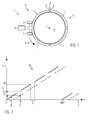
- the absolute value encoder 1 can have an evaluation unit 2, which can be connected in signal-transmitting manner to a first and a second sensor 3, 4. Furthermore, the absolute value encoder 1 can comprise at least one material measure 5.
- the measuring graduation 5 can be fastened to a body 6 whose absolute position P is determined with reference to the absolute value transmitter 1 or with reference to one of the two sensors 3, 4 shall be.
- absolute positions P encoded as measurement position values in the material measure 5 are read out by at least one of the sensors 3, 4 and the absolute position P is derived from the measurement position values.
- the measuring graduation 5 is fastened to a circular-cylindrical body 6.
- the body 6 may be formed as a hub or shaft of a wind turbine and may be, for example, the rotor hub or a shaft driving a generator.
- the absolute value encoder 1 according to the invention can also be used with other shafts, hubs or other shaped and possibly not only rotationally moving bodies 6.
- the material measure 5 can be arranged along a measurement path M, wherein the measurement path M in the exemplary embodiment illustrated here runs parallel to a circumferential direction U on a lateral surface of the body 6.
- the absolute value encoder 1 is thus shown as a rotary encoder.
- the absolute value encoder 1 can also determine absolute positions P of translationally moving bodies 6. Combinations of translational and rotational movements of the body 6 with respect to the absolute value transmitter 1 or relative to its sensors 3, 4 can determine the absolute value encoder 1.
- the material measure 5 can be arranged along an arbitrarily predetermined measurement path M.
- the material measure 5 can comprise a plurality of integral parts 7 which can be arranged separately on the body 6 or along the measurement path M.
- the material measure 5 can comprise a plurality of integral parts 7 which can be arranged separately on the body 6 or along the measurement path M.
- measuring scales 5 can be mounted on bodies 6, even if the body 6 is relatively large.
- a shaft for the generator of the windmill may have a diameter of up to one meter or more. Individual parts 7 of the material measure 5 can therefore possibly be easily attached by a single installer on the jacket of the shaft.
- the material measure 5 comprises, for example, four parts 7 which are arranged one behind the other along the measurement path M so that the body 6 is essentially surrounded in its circumferential direction U by the parts 7 forming the material measure 5.
- the parts 7 can have the coding of the absolute position P of the body 6, which can be scanned by the two sensors 3, 4.
- the coding may have the measurement position values that may assume discrete values.
- ends 8 of the parts 7 along the measuring path M or in the circumferential direction U can be arranged abutting or spaced from each other.
- the material measure 5 can also be made of several parts 7, which are integrally connected to one another.
- the absolute position P of the body 6 between two adjacent parts 7 or between the mutually facing ends 8 of two parts 7 is not represented as expected by measuring position values.
- the measurement position values in the region of the adjoining ends 8 of two codings of the parts 7 can have an unexpectedly large difference to one another, which does not represent the true, physical distance of the encoded measurement position values in the region of the adjacent ends 8 from one another. This difference can lead to an unexpected jump of the coding.
- the coding may be interrupted at least between the adjacent but spaced-apart ends 8. Such a gap in the coding can for example be caused by ends 8 of two parts 7, which are arranged at a distance from each other. It may also happen that the parts 7 are not or not properly coded in the region of the ends 8. Both the difference not representing the true distance and the gap can be detected by the absolute value encoder 1 as a discontinuity 9 in the coding.
- the sensors 3, 4 can be arranged along the measuring path M so that at least one of the two sensors 3, 4 always has valid measuring position values outside the discontinuity 9 of the material measure 5 can lose weight.
- the sensors 3, 4 along the measuring path M at least so far apart from each other be arranged so that the distance of the sensors 3, 4 to each other at least the geometric dimensions of the discontinuity 9 or the true distance along the measuring path M.
- the distance of the sensors 3, 4 from one another may be greater than the geometric dimensions of the discontinuity 9.
- the distance between the two sensors 3, 4 can be predetermined or determined during commissioning and be known in the absolute encoder 1.
- the measuring standard 5 can alternatively consist of a single piece, which can be arranged along the measuring path M and, for example, wound around the body 6.
- the two ends 8 such a material measure 5 along the measuring path M be arranged opposite to each other.
- This material measure 5 can thus have a continuous coding, which is arranged in a single coding section along the measuring path M and interrupted at only one point by the discontinuity 9.
- each of the parts 7 can have such a coding section in which the absolute position P is clearly coded.
- the parts 7 can be coded identically, so that the absolute position P can be clearly established within each of the parts 7.
- the amount of measurement position values of each part 7 can be identical.
- the absolute position of the body 6 over several parts 7 can be determined by determining the discontinuities 9 that have occurred during a movement of the body 6. Further, the parts 7 may include individual identification data. Alternatively, the parts 7 may be coded so that they represent a continuous encoded absolute position P except for the discontinuities 9.
- Fig. 2 shows measured position values W taken by the sensors 3, 4 of the absolute value transmitter 1 of the exemplary embodiment of FIG Fig. 1 ,
- Fig. 2 In the Fig. 2 are possible measuring position values W of the rotary encoder 1 of the embodiment of Fig. 1 represented in a coordinate system. Recorded valid measurement position values W of the sensor 3 are shown as solid and the sensor 4 as dashed sections. The actual physical absolute position P of the shaft 6 is plotted on the X axis of the coordinate system and the derived absolute position values L on the Y axis. In the illustration shown, the sensor 3 passes over five parts 7 of the measuring standard 5 of the exemplary embodiment of FIG Fig. 1 , This corresponds to a rotation of the body 6 about its longitudinal axis Z by about 450 °.
- the determination of the absolute position values L on the basis of the determined measurement position values W is shown by way of example at two support points 10, 11.
- the sensor 3 is located above one of the parts 7 or via its coding section.
- the measurement position value W can be uniquely assigned to the associated absolute position value L.
- the body 6 is further rotated, so that the sensor 3 is arranged above a discontinuity 9 formed as a gap and can not read off any valid measurement position values W from the material measure 5.
- the second sensor 4 is above the Coding section of read by the sensor 3 read before rotation part 7 and provides a valid measurement position value W.
- the measured position value W recorded at the support point 11 is converted into a provisional absolute position value L, which is then offset to determine the true absolute position value L with respect to the sensor 3 A is added.
- the offset value A corresponds to the distance between the two sensors 3, 4 relative to one another along the measurement path M and can be stored in absolute position values L or measurement position values W in the absolute value encoder 1.
- the measurement position values W of the sensors 3, 4 lie here in each case on a straight line. This means that the ends of the coding sections of two parts 7 are coded according to their true, physical distance from each other. The discontinuity 9 thus arises here exclusively by the absence of measurement position values W in the gap between the parts 7.
- the difference of the coded measuring position values W in the region of the ends 8 of the successive parts 7 can also be greater or smaller than the true distance, which leads to a discontinuity.
- the individual sections of the measurement position values W assigned to one of the parts 7 would in such a case not be aligned with one another on a straight line, but would be arranged offset parallel to this straight line. At least in such a case, a training run for learning the relation between the determined measurement position values W and the absolute position values L and the absolute positions P would be performed.
- the length of the discontinuity 9, for example the gap, along the measuring path M can likewise vary, which in addition can lead to a shift in the linear sections representing the measuring position values W along the straight line.
- Other sources of error such as local stretching or twisting of the measuring scale 5 during assembly or environmental influences, may influence the position or orientation of the sections of valid measuring position values W or the size of the discontinuity 9.
- the plausibility of the measurement position values W of one of the sensors 3, 4 can be determined. If the measurement position values W of one sensor 3, 4 are not plausible, for example invalid or completely missing, then the measurement position values W of the other sensor 4, 3 can be used and linked to the offset value A. Alternatively or additionally, measurement position values W of one of the sensors 3, 4 can only be used for a predetermined amount of measurement position values W are evaluated. Outside this set of measurement position values W, the sampled measurement position values W of the other sensor 4, 3 can be used.
- Fig. 3 shows a further embodiment, wherein for elements that in function and / or structure of the elements of the embodiment of Fig. 1 or 2 correspond, the same reference numerals are used. For brevity, only the differences from the embodiments of the Fig. 1 and 2 received.
- Fig. 3 are measured position values W, wherein the parts 7 of the embodiment of the Fig. 1 all are coded identically.
- the absolute value encoder 1 For determining the absolute position value L, it is necessary for the absolute value encoder 1 to have information about the respectively sampled part 7. Since the parts 7 are coded identically, the absolute value encoder 1 can determine this information, for example, by counting the discontinuities 9 that have occurred. In the case of a transition from one part 7 to another part 7, eg after a gap D1, the coding jumps at a discontinuity S1 by, for example, 1000 measuring position values or also units.
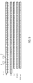
- Fig. 4 shows a schematic representation of an embodiment of a method for determining absolute positions P by means of measurement position values W, with an absolute value encoder 1 according to the embodiments of the Fig. 1 and 2 is formed.
- the discontinuities 9 of the Fig. 4 have jump gaps S in addition to gaps D.
- the distance between the two sensors 3, 4 is in the exemplary embodiment shown seven measurement position values W or units, so that the offset value A is equal to seven.
- the sensors 3, 4 are arranged at measuring points M3, M4 with respect to the material measure 5.
- absolute values L are plotted.
- the coding of the material measure 5 with four parts 7, 7 ', 7 ", 7'” is shown, each having a coding section A, B, C, D.
- Each of the discontinuities 9, 9 ', 9" comprises a gap D1, D2, D3, through which the parts 7 , 7 ', 7 ", 7"' spaced apart along the measuring path M are arranged.
- the gap D1 is three units, the gap D2 two units and the gap D3 four units. Further, the discontinuity 9 is formed with a jump in size of minus two units. The Discontinuity 9 'includes a jump of four units and the discontinuity 9 "of minus three units.
- the coding sections A, B, C, D comprise different sets of measuring position values W, the part 7 starting with a measuring position value W of 1, which is arranged at a position K1. In position K2 following position K1, the measuring position value W is equal to two. Successive positions Kn are provided with successive measurement values W for all parts 7, 7 ', 7 ", 7"'.
- the measured position values W detected by the two sensors 3, 4 are shown when the measuring scale 5 is passed over. In the area of the gaps D1, D2, D3, the sensors 3, 4 do not detect any measured position values W, since these are not present here. However, due to the distance of seven units between the sensors 3, 4, the measured position values W of the two sensors 3, 4 offset by the offset value of seven, so that gaps D1, D2, D3 in the sampled measurement position values X3 of measurement position values W in the Line X4 are bridged.
- the absolute position P of the body 6 should be determined here with reference to the sensor 3. If the sensor 3 passes over the coding section A, then the measuring position values W, X3 taken from it can be directly assigned to the absolute position values L or correspond to them.
- the part 7 is a first or reference part.
- the sensor 3 does not perceive any measurement position values W, so that the measurement position values L are determined from the measured position values W, X4 of the sensor 4, to which the offset value A is added.
- This position correction can also be carried out at the position K11 of the coding K.
- the value thus calculated is here designated W, X4, K11.
- the compensation factor E is composed of the measured position value W, X4, K11, the offset value A and the measuring position value W valid at the point K11 by the sensor 4, wherein the value W, X, K11 is added to the offset value A and the measurement position value W of the point K11 is subtracted therefrom.
- the removed measurement position value W, X4 of the sensor 4 is to be linked additively with the offset value A and with the compensation factor E.
- This can also be done in K21.
- the measured position value W, X3 picked up by the sensor 3 can be additively linked to the offset value A, the compensation factor E and to a further compensation factor E '.
- the further compensation factor E ' can be constructed analogously to the factor E, wherein the respective measurement position values W are related to the current section 7 "of the material measure 5 - the measurement position value W, X4, K21 taken at the point K21 by the sensor 4 becomes the offset value A additive linked and subtracted the value of the point K21 herebefore.
- the measured position value W, X4 removed by the sensor 4 can be additively linked to the offset value A. Furthermore, the two compensation factors E, E 'are linked to the measurement position value W, X4.
- the measurement position values W, X3, X4 sampled by the sensors 3, 4 from further parts 7 of the material measure 5 can also be corrected in an analogue manner and converted into absolute position values L.
- Fig. 5 shows a schematic representation of an embodiment of a method for determining absolute position P on the basis of measurement position values W, in which the parts 7 of the material measure 5 as in Fig. 3 are shown identically encoded.
- the distance A of the two sensors 3, 4 to each other here is 8 measurement position values W or units.
- the respective parts 7, 7 ', 7 “, 7'” are arranged separated from one another by discontinuities 9, 9 ', 9 "and in particular by gaps D1, D2, D3 along the measuring path M.
- the gap D1 is two units
- the gap D2 is four
- the gap D3 is three units
- the transition from one part 7, 7 ', 7 ", 7" to another part 7, 7', 7 ", 7 '” is minus 10 units
- X4 show again taken measuring position values W.
- the line L over is shown again by way of example a calculation method used for the position correction and the determination of the absolute position values L on the basis of the taken measuring position values X3, X4 Fig. 4 Calculation rule shown can also in the embodiment of Fig. 5 Find application.
- Fig. 6 shows a further embodiment of the absolute value encoder 1 according to the invention, wherein for elements that in function and / or structure of the elements of the embodiments of the Fig. 1 to 5 correspond, the same reference numerals are used. For brevity, only the differences from the embodiments of the Fig. 1 to 5 received.
- Fig. 6 only part 7 of the measuring standard 5 is shown mounted on the body 6. Other parts 7 may already be mounted or later still be mounted. Alternatively, the material measure 5 can comprise only a part 7. The position shown of the part 7 is shown mounted incorrectly perpendicular to the measuring path M or to the body 6, whereby the read out measurement position values W can no longer be assigned to the absolute position P without further ado.
- the part 7 is arranged radially offset from the longitudinal axis Z of the body 6.
- Such a task may also arise without problems associated with discontinuity 9.
- the absolute value encoder 1 can be used.
- the part 7 can be moved past the sensors 3, 4 along the measuring path M and, to determine the type and size of the incorrect assembly, they both simultaneously remove the measured position values W from the part 7 and forward them to the evaluation unit 2.
- the measured measurement position values W of the two sensors 3, 4 can be compared, resulting in a representative of the type and size of incorrect assembly error signal F, which in the Fig. 7 is shown.
- the Fig. 7 shows processed measurement position values W and W ", which each originate from one of the sensors 3, 4.
- the measurement position values W 'of the sensor 4 are corrected by linking with the offset value A.
- the offset value A can be added to the measurement position value W determined by the sensor 4 If measuring position values W of different parts 7 are used, then the compensation factor K which takes account of the discontinuity 9 must also be used for the position correction, and this position correction of the measurement position values W, W 'can be compared directly with one another.
- the Fig. 7 the deviation of the determined measurement position values W, W 'from an ideal course of expected measurement values to be measured is shown. It can be seen that the position-corrected measuring position values W, W 'are close to each other at the beginning, ie at 0 °, for example. These measurement position values W ', W' can be recorded in the region of one of the ends 8 of the part 7, which is arranged very close to the measurement path M. In their course, these measured position values W, W 'move away from each other up to a maximum distance of about 90 °, in order then to be close to each other again at about 180 °.
- the course shown here by way of example corresponds to the radial offset of part 7 of Fig.
- the resulting shape curves of the deviation of the specific measurement position values W, W 'from the ideal measurement position values and also the resulting measurement signal and fault signal F can be characteristic of the respective faulty assembly.
- the determined curves represent a user or fitter or evaluated automatically by the absolute encoder 1.
- Fig. 8 shows a further embodiment of the absolute value encoder 1 according to the invention, wherein for elements which correspond in function and / or construction to the elements of the embodiments of the previous figures, the same reference numerals are used. For brevity, only the differences from the embodiments of the previous figures will be discussed.
- Fig. 8 shows the absolute value encoder 1 schematically with various functional units.
- the functional units can be designed as separate elements or as functions of a single element, for example the evaluation unit 2. Alternatively or additionally, each of the functional units can be implemented as software.
- the two sensors 3, 4 may be signal transmitting connected to an absolute position value output unit 12 of the absolute value encoder 1, wherein the Measurement position values W of one of the sensors 3, 4, for example of the first sensor 3, can be passed unchanged to the absolute position value output unit 12.
- the second sensor 4, which is arranged at a distance from the sensor 3, can first be connected in a signal-transmitting manner to a position correction unit 13 and transmit the measurement position values W determined by it to this unit 13.
- the position correction unit 13 may be data-transmitting connected to a memory unit 14, in which the offset value A can be stored permanently.
- the compensator 15 can be provided, which combines the determined measuring position values W at least with the offset value A and adds them together, for example. As a result of this linkage, the position correction unit 13 can output the position-corrected measurement position values W of the sensor 4 to the absolute position value output unit 12.
- the absolute position value output unit 12 can automatically decide which of the supplied measurement position values W should be used to determine the absolute position P.
- an inspection unit not shown here, can be arranged between the absolute position value output unit 12 and the sensors 3, 4, to which the measuring position values W of both sensors 3, 4 are fed and which only one of the two measuring position values W after their testing to determine the absolute position P at the Absolute level output unit 12 outputs.
- a further sensor 3 'can be provided.
- the function of the further sensor 3 'can be fulfilled by one of the sensors 3, 4. If one of the discontinuities 9 passes the further sensor 3 ', it recognizes the passing discontinuity 9 and outputs a signal to a nonvolatile memory 16.
- the passage of the discontinuities 9 can be documented. As a result, for example, the function of a so-called multi-turn encoder can be displayed. Further, each of the sensors 3, 4 just scanned parts 7 can be identified.
- the further sensor 3 can be used as a generator and, for example, as a so-called microgenerator may be formed.
- the generator can generate a signal even in the switched-off state of the absolute encoder 1, which can be documented in the nonvolatile memory 16.
- the discontinuity 9, in particular the gap D1, D2, D3, may include at least one microgenerator actuating element, for example a magnet.
- the test unit 17, the measurement position values W of both sensors 3, 4 are supplied on the input side.
- a representative of the type and size of incorrect assembly error signal F can be generated and then output.
- the determined measurement position values W can be compared with ideal measurement position values in the test unit 17.
- the representative signal as in the description of the embodiment of Fig. 7 can be generated represented.
- the determined and positionally corrected measurement position values W can be evaluated directly or relative velocities between the sensors 3, 4 and the body 6 along the measurement path M derived from the measurement position values W of the two sensors 3, 4 can be determined.
- the determined speeds can also be used to determine the incorrect assembly F representing the signal and, for this purpose, for example, be subtracted from each other.
- the test unit 17 can be signal-transmitting connected to the compensator 15 or the absolute position value output unit 12, so that 5 may possibly be compensated by the incorrect assembly of the material measure corresponding inaccuracies of the absolute position determination.
- Fig. 9 shows an embodiment of a method for determining the incorrect assembly of the material measure 5.
- the measuring scale 5 is misassembled in a central area and bulges, for example, from the measuring path M in the direction of the sensors 3, 4.
- This embodiment is similar to the embodiment of the Fig. 6 ,
- the material measure 5 is arranged along the measuring path M.
- the position of the measuring standard 5 deviates from the measuring path M perpendicular to this.
- measuring position values W adjacent to one another appear closer to one another from the perspective of the sensors 3, 4, which can lead to a faster change in the measured position values W in the range of the positions K9 to K20 during operation and is represented by the omission of measuring position values W.
- the distance of the sensors 3, 4 is in this embodiment only 2 units.
- the measured position values W sampled by the sensor 3 are shown
- corr is position corrected and taken by the sensor 4 Measurement position values W, X4 shown.
- the offset value A is added to these.
- the position-corrected measurement position values W, X4 sampled by the sensor 4 are subtracted from the measurement position values W, X3 sampled by the sensor 3.
- the difference of the position-corrected measurement position values W is constant and in particular 0.
- this difference deviates from the constant value from where the difference at the position K16 reaches its maximum. Based on the shape of the resulting from the difference values error function can be determined both size and shape of the incorrect assembly.
Applications Claiming Priority (1)
| Application Number | Priority Date | Filing Date | Title |
|---|---|---|---|
| DE102010061737A DE102010061737A1 (de) | 2010-11-22 | 2010-11-22 | Absolutwertgeber mit Sprungstelle in kodierter Absolutlage |
Publications (2)
| Publication Number | Publication Date |
|---|---|
| EP2455721A2 true EP2455721A2 (fr) | 2012-05-23 |
| EP2455721A3 EP2455721A3 (fr) | 2015-01-07 |
Family
ID=45348994
Family Applications (1)
| Application Number | Title | Priority Date | Filing Date |
|---|---|---|---|
| EP11188327.8A Withdrawn EP2455721A3 (fr) | 2010-11-22 | 2011-11-08 | Codeur absolu doté d'un point de discontinuité dans une position absolue codée |
Country Status (3)
| Country | Link |
|---|---|
| US (1) | US8584370B2 (fr) |
| EP (1) | EP2455721A3 (fr) |
| DE (1) | DE102010061737A1 (fr) |
Cited By (1)
| Publication number | Priority date | Publication date | Assignee | Title |
|---|---|---|---|---|
| EP2801795A1 (fr) * | 2013-05-07 | 2014-11-12 | Baumer Hübner GmbH | Tête de balayage pour un capteur |
Families Citing this family (10)
| Publication number | Priority date | Publication date | Assignee | Title |
|---|---|---|---|---|
| DE102010061738A1 (de) * | 2010-11-22 | 2012-04-26 | Baumer Innotec Ag | Verfahren und Inkrementalwertgeber zur Bestimmung einer Istlage eines Körpers entlang eines Messweges mit einer wenigstens eine Lücke aufweisenden Maßverkörperung |
| DE102010061737A1 (de) * | 2010-11-22 | 2012-05-24 | Baumer Innotec Ag | Absolutwertgeber mit Sprungstelle in kodierter Absolutlage |
| GB201100190D0 (en) * | 2011-01-07 | 2011-02-23 | Rls Merlina Tehnika D O O | Encoder readhead apparatus |
| JP6014489B2 (ja) * | 2012-12-26 | 2016-10-25 | キヤノン株式会社 | 駆動装置およびそれを有するレンズ装置及び撮影装置 |
| US10309760B2 (en) * | 2014-10-08 | 2019-06-04 | Candy House Inc. | Angle of rotation sensor, a linear displacement sensor, a door mount mechanism, and an electrical brush |
| DE102016222275A1 (de) * | 2016-11-14 | 2018-05-17 | Dr. Johannes Heidenhain Gmbh | Positionsmesseinrichtung und Verfahren zum Betreiben einer Positionsmesseinrichtung |
| DE102018128023A1 (de) * | 2018-11-09 | 2020-05-14 | Schaeffler Technologies AG & Co. KG | Linearführung |
| IT202100006692A1 (it) * | 2021-03-19 | 2022-09-19 | Lika Electronic S R L | Apparecchiatura di trasduzione di posizione/spostamenti e sistema e metodo correlati |
| DE102021118091A1 (de) | 2021-07-13 | 2023-01-19 | Neura Robotics GmbH | Encodersystem sowie Verfahren zur Bestimmung der Lesekopfposition in einem Encodersystem |
| EP4309905A1 (fr) | 2022-07-21 | 2024-01-24 | Habasit International AG | Courroie de transporteur dotée de marqueurs magnétiques lisibles par un codeur linéaire magnétique |
Family Cites Families (9)
| Publication number | Priority date | Publication date | Assignee | Title |
|---|---|---|---|---|
| GB2197146B (en) * | 1986-11-04 | 1991-05-29 | Canon Kk | An encoder for detecting the displacement of an object to be measured |
| DE58902407D1 (de) * | 1988-07-07 | 1992-11-12 | Oerlikon Geartec Ag | Positionslesesystem fuer ueber 360o verschwenkbare werkzeugmaschinenteile. |
| DE19532903A1 (de) * | 1995-09-07 | 1997-03-13 | Teves Gmbh Alfred | Lenkwinkelsensor mit Absolutwertmessung |
| DE19628765B4 (de) * | 1996-07-17 | 2007-04-05 | Braun, Paul-Wilhelm, Dipl.-Ing. | Verfahren und Vorrichtung zur Positionsbestimmung von nicht-geradlinig bewegten, insbesondere rotierenden Maschinenteilen |
| DE102004033990B3 (de) * | 2004-07-14 | 2006-04-13 | Siemens Ag | Auswerteverfahren für ein analoges Erstsignal und ein analoges Zweitsignal sowie hiermit korrespondierende Auswerteschaltung |
| US7432497B2 (en) * | 2005-09-29 | 2008-10-07 | Mitutoyo Corporation | Absolute linear encoder |
| EP2357451B1 (fr) * | 2010-02-09 | 2011-11-16 | SICK STEGMANN GmbH | Dispositif de mesure destiné à la détermination de la valeur absolue de longueurs ou d'angles avec une echelle de mesure active composée de plusieurs parties adjacentes |
| DE102010061738A1 (de) * | 2010-11-22 | 2012-04-26 | Baumer Innotec Ag | Verfahren und Inkrementalwertgeber zur Bestimmung einer Istlage eines Körpers entlang eines Messweges mit einer wenigstens eine Lücke aufweisenden Maßverkörperung |
| DE102010061737A1 (de) * | 2010-11-22 | 2012-05-24 | Baumer Innotec Ag | Absolutwertgeber mit Sprungstelle in kodierter Absolutlage |
-
2010
- 2010-11-22 DE DE102010061737A patent/DE102010061737A1/de not_active Ceased
-
2011
- 2011-11-08 EP EP11188327.8A patent/EP2455721A3/fr not_active Withdrawn
- 2011-11-21 US US13/301,264 patent/US8584370B2/en not_active Expired - Fee Related
Non-Patent Citations (1)
| Title |
|---|
| None |
Cited By (3)
| Publication number | Priority date | Publication date | Assignee | Title |
|---|---|---|---|---|
| EP2801795A1 (fr) * | 2013-05-07 | 2014-11-12 | Baumer Hübner GmbH | Tête de balayage pour un capteur |
| WO2014180879A1 (fr) * | 2013-05-07 | 2014-11-13 | Baumer Huebner Gmbh | Tête de palpage |
| US10066963B2 (en) | 2013-05-07 | 2018-09-04 | Baumer Huebner Gmbh | Scanning head |
Also Published As
| Publication number | Publication date |
|---|---|
| DE102010061737A1 (de) | 2012-05-24 |
| US20120124848A1 (en) | 2012-05-24 |
| US8584370B2 (en) | 2013-11-19 |
| EP2455721A3 (fr) | 2015-01-07 |
Similar Documents
| Publication | Publication Date | Title |
|---|---|---|
| EP2455721A2 (fr) | Codeur absolu doté d'un point de discontinuité dans une position absolue codée | |
| EP2225142B1 (fr) | Arrangement de detection de l'angle de direction a mesure absolue | |
| EP2443419B1 (fr) | Procédé et dispositif pour déterminer la valeur de position fine d'un corps mobile | |
| DE19712622B4 (de) | Anordnung und Verfahren zur automatischen Korrektur fehlerbehafteter Abtastsignale inkrementaler Positionsmeßeinrichtungen | |
| EP1313999B1 (fr) | Procede et dispositif de mesure d'angles | |
| EP2551645B1 (fr) | Dispositif et procédé destinés à la mesure d'un angle | |
| EP2329225B1 (fr) | Capteur de position inductif, système de mesure équipé de ce capteur et procédé pour faire fonctionner un tel capteur de position | |
| EP2455722B1 (fr) | Procédé et générateur de valeurs incrémentielles destinés à la détermination de la position réelle d'un corps le long d'une trajectoire de mesure doté d'un corps de mesure comprenant au moins un creux | |
| EP1855080A2 (fr) | Procédé et dispositif destinés à la mesure d'une trajectoire parcourue | |
| DE102010041444A1 (de) | Geberrad einer Sensoranordnung zum Erfassen eines Drehwinkels und/oder einer Drehzahl einer Welle, Drehwinkel- und/oder Drehzahlsensor und Sensoranordnung | |
| DE102004002722B4 (de) | Absoluter Codierer, der auf einem inkrementalen Codierer beruht | |
| DE102012205902A1 (de) | Weggeber zum berührungslosen Messen einer Position mittels einer Vielzahl von in Reihe angeordneten Magnetfeldsensoren | |
| DE102012202639A1 (de) | Sensoranordnung zur Erfassung von Drehwinkeln an einem rotierenden Bauteil in einem Fahrzeug | |
| WO2011107070A1 (fr) | Arbre de mesure de couple | |
| WO1986003258A1 (fr) | Procede d'ajustage pour un organe detecteur de position, en particulier dans un vehicule a moteur | |
| EP3527950B1 (fr) | Dispositif de mesure d'angle sans palier | |
| DE102012202657A1 (de) | Sensoranordnung zur Erfassung von Drehwinkeln an einem rotierenden Bauteil in einem Fahrzeug | |
| EP2187175B1 (fr) | Convertisseur de mesure | |
| DE10041096A1 (de) | Verfahren zur Korrektur von Winkelmessungen mittels wenigstens zweier Codespuren | |
| DE102008048506B4 (de) | Verfahren und Vorrichtung zum Kalibrieren eines Sensors, Verfahren und System zum Bestimmen einer Einstellposition einer Schaltwelle eines Getriebes und Sensor zum Erfassen einer Einstellposition einer Schaltwelle eines Getriebes | |
| WO2016083011A2 (fr) | Procédé et dispositif d'étalonnage d'un dispositif générateur de signaux d'un module à pédale de frein haptique pour véhicule à moteur ainsi que module à pédale de frein haptique | |
| DE102004001570B4 (de) | Messverfahren sowie Messvorrichtung zum Durchführen des Messverfahrens | |
| DE102010051873B4 (de) | Integrierte Schaltungsanordnung und Verfahren zur Signalüberwachung | |
| EP3228994A1 (fr) | Dispositif et procédé destinés à la mesure d'un angle | |
| DE102009023515B4 (de) | Verfahren und Vorrichtung zur Ermittlung des Feinpositionwertes eines zu überwachenden Körpers |
Legal Events
| Date | Code | Title | Description |
|---|---|---|---|
| PUAI | Public reference made under article 153(3) epc to a published international application that has entered the european phase |
Free format text: ORIGINAL CODE: 0009012 |
|
| AK | Designated contracting states |
Kind code of ref document: A2 Designated state(s): AL AT BE BG CH CY CZ DE DK EE ES FI FR GB GR HR HU IE IS IT LI LT LU LV MC MK MT NL NO PL PT RO RS SE SI SK SM TR |
|
| AX | Request for extension of the european patent |
Extension state: BA ME |
|
| RAP1 | Party data changed (applicant data changed or rights of an application transferred) |
Owner name: BAUMER HUEBNER GMBH |
|
| RIC1 | Information provided on ipc code assigned before grant |
Ipc: G01D 5/249 20060101AFI20140804BHEP Ipc: G01D 5/244 20060101ALI20140804BHEP Ipc: G01D 5/347 20060101ALI20140804BHEP |
|
| PUAL | Search report despatched |
Free format text: ORIGINAL CODE: 0009013 |
|
| AK | Designated contracting states |
Kind code of ref document: A3 Designated state(s): AL AT BE BG CH CY CZ DE DK EE ES FI FR GB GR HR HU IE IS IT LI LT LU LV MC MK MT NL NO PL PT RO RS SE SI SK SM TR |
|
| AX | Request for extension of the european patent |
Extension state: BA ME |
|
| RIC1 | Information provided on ipc code assigned before grant |
Ipc: G01D 5/244 20060101ALI20141203BHEP Ipc: G01D 5/249 20060101AFI20141203BHEP Ipc: G01D 5/347 20060101ALI20141203BHEP |
|
| STAA | Information on the status of an ep patent application or granted ep patent |
Free format text: STATUS: THE APPLICATION IS DEEMED TO BE WITHDRAWN |
|
| 18D | Application deemed to be withdrawn |
Effective date: 20150708 |