EP2455721A2 - Absolute encoder with jump discontinuity in encoded absolute position - Google Patents
Absolute encoder with jump discontinuity in encoded absolute position Download PDFInfo
- Publication number
- EP2455721A2 EP2455721A2 EP11188327A EP11188327A EP2455721A2 EP 2455721 A2 EP2455721 A2 EP 2455721A2 EP 11188327 A EP11188327 A EP 11188327A EP 11188327 A EP11188327 A EP 11188327A EP 2455721 A2 EP2455721 A2 EP 2455721A2
- Authority
- EP
- European Patent Office
- Prior art keywords
- absolute
- measuring
- discontinuity
- coding
- position values
- Prior art date
- Legal status (The legal status is an assumption and is not a legal conclusion. Google has not performed a legal analysis and makes no representation as to the accuracy of the status listed.)
- Withdrawn
Links
- 238000005259 measurement Methods 0.000 claims abstract description 111
- 238000000034 method Methods 0.000 claims abstract description 18
- 239000000463 material Substances 0.000 claims description 62
- 238000012360 testing method Methods 0.000 claims description 15
- 230000007704 transition Effects 0.000 claims description 5
- 238000012545 processing Methods 0.000 claims description 2
- 230000005540 biological transmission Effects 0.000 claims 1
- 230000006870 function Effects 0.000 description 10
- 238000012937 correction Methods 0.000 description 9
- 238000011156 evaluation Methods 0.000 description 5
- 238000004519 manufacturing process Methods 0.000 description 4
- 238000004364 calculation method Methods 0.000 description 3
- 238000006243 chemical reaction Methods 0.000 description 3
- 230000001788 irregular Effects 0.000 description 2
- 238000012549 training Methods 0.000 description 2
- OKTJSMMVPCPJKN-UHFFFAOYSA-N Carbon Chemical compound [C] OKTJSMMVPCPJKN-UHFFFAOYSA-N 0.000 description 1
- 239000000654 additive Substances 0.000 description 1
- 230000000996 additive effect Effects 0.000 description 1
- 238000010276 construction Methods 0.000 description 1
- 230000007547 defect Effects 0.000 description 1
- 238000001514 detection method Methods 0.000 description 1
- 238000011161 development Methods 0.000 description 1
- 230000007613 environmental effect Effects 0.000 description 1
- 229910021389 graphene Inorganic materials 0.000 description 1
- 238000007689 inspection Methods 0.000 description 1
- 239000007787 solid Substances 0.000 description 1
Images


Classifications
-
- G—PHYSICS
- G01—MEASURING; TESTING
- G01D—MEASURING NOT SPECIALLY ADAPTED FOR A SPECIFIC VARIABLE; ARRANGEMENTS FOR MEASURING TWO OR MORE VARIABLES NOT COVERED IN A SINGLE OTHER SUBCLASS; TARIFF METERING APPARATUS; MEASURING OR TESTING NOT OTHERWISE PROVIDED FOR
- G01D5/00—Mechanical means for transferring the output of a sensing member; Means for converting the output of a sensing member to another variable where the form or nature of the sensing member does not constrain the means for converting; Transducers not specially adapted for a specific variable
- G01D5/12—Mechanical means for transferring the output of a sensing member; Means for converting the output of a sensing member to another variable where the form or nature of the sensing member does not constrain the means for converting; Transducers not specially adapted for a specific variable using electric or magnetic means
- G01D5/244—Mechanical means for transferring the output of a sensing member; Means for converting the output of a sensing member to another variable where the form or nature of the sensing member does not constrain the means for converting; Transducers not specially adapted for a specific variable using electric or magnetic means influencing characteristics of pulses or pulse trains; generating pulses or pulse trains
- G01D5/249—Mechanical means for transferring the output of a sensing member; Means for converting the output of a sensing member to another variable where the form or nature of the sensing member does not constrain the means for converting; Transducers not specially adapted for a specific variable using electric or magnetic means influencing characteristics of pulses or pulse trains; generating pulses or pulse trains using pulse code
- G01D5/2497—Absolute encoders
-
- G—PHYSICS
- G01—MEASURING; TESTING
- G01D—MEASURING NOT SPECIALLY ADAPTED FOR A SPECIFIC VARIABLE; ARRANGEMENTS FOR MEASURING TWO OR MORE VARIABLES NOT COVERED IN A SINGLE OTHER SUBCLASS; TARIFF METERING APPARATUS; MEASURING OR TESTING NOT OTHERWISE PROVIDED FOR
- G01D5/00—Mechanical means for transferring the output of a sensing member; Means for converting the output of a sensing member to another variable where the form or nature of the sensing member does not constrain the means for converting; Transducers not specially adapted for a specific variable
- G01D5/12—Mechanical means for transferring the output of a sensing member; Means for converting the output of a sensing member to another variable where the form or nature of the sensing member does not constrain the means for converting; Transducers not specially adapted for a specific variable using electric or magnetic means
- G01D5/244—Mechanical means for transferring the output of a sensing member; Means for converting the output of a sensing member to another variable where the form or nature of the sensing member does not constrain the means for converting; Transducers not specially adapted for a specific variable using electric or magnetic means influencing characteristics of pulses or pulse trains; generating pulses or pulse trains
- G01D5/24471—Error correction
- G01D5/24476—Signal processing
-
- G—PHYSICS
- G01—MEASURING; TESTING
- G01D—MEASURING NOT SPECIALLY ADAPTED FOR A SPECIFIC VARIABLE; ARRANGEMENTS FOR MEASURING TWO OR MORE VARIABLES NOT COVERED IN A SINGLE OTHER SUBCLASS; TARIFF METERING APPARATUS; MEASURING OR TESTING NOT OTHERWISE PROVIDED FOR
- G01D5/00—Mechanical means for transferring the output of a sensing member; Means for converting the output of a sensing member to another variable where the form or nature of the sensing member does not constrain the means for converting; Transducers not specially adapted for a specific variable
- G01D5/26—Mechanical means for transferring the output of a sensing member; Means for converting the output of a sensing member to another variable where the form or nature of the sensing member does not constrain the means for converting; Transducers not specially adapted for a specific variable characterised by optical transfer means, i.e. using infrared, visible, or ultraviolet light
- G01D5/32—Mechanical means for transferring the output of a sensing member; Means for converting the output of a sensing member to another variable where the form or nature of the sensing member does not constrain the means for converting; Transducers not specially adapted for a specific variable characterised by optical transfer means, i.e. using infrared, visible, or ultraviolet light with attenuation or whole or partial obturation of beams of light
- G01D5/34—Mechanical means for transferring the output of a sensing member; Means for converting the output of a sensing member to another variable where the form or nature of the sensing member does not constrain the means for converting; Transducers not specially adapted for a specific variable characterised by optical transfer means, i.e. using infrared, visible, or ultraviolet light with attenuation or whole or partial obturation of beams of light the beams of light being detected by photocells
- G01D5/347—Mechanical means for transferring the output of a sensing member; Means for converting the output of a sensing member to another variable where the form or nature of the sensing member does not constrain the means for converting; Transducers not specially adapted for a specific variable characterised by optical transfer means, i.e. using infrared, visible, or ultraviolet light with attenuation or whole or partial obturation of beams of light the beams of light being detected by photocells using displacement encoding scales
- G01D5/34707—Scales; Discs, e.g. fixation, fabrication, compensation
-
- G—PHYSICS
- G01—MEASURING; TESTING
- G01D—MEASURING NOT SPECIALLY ADAPTED FOR A SPECIFIC VARIABLE; ARRANGEMENTS FOR MEASURING TWO OR MORE VARIABLES NOT COVERED IN A SINGLE OTHER SUBCLASS; TARIFF METERING APPARATUS; MEASURING OR TESTING NOT OTHERWISE PROVIDED FOR
- G01D2205/00—Indexing scheme relating to details of means for transferring or converting the output of a sensing member
- G01D2205/70—Position sensors comprising a moving target with particular shapes, e.g. of soft magnetic targets
- G01D2205/77—Specific profiles
- G01D2205/774—Profiles with a discontinuity, e.g. edge or stepped profile
Definitions
- the invention relates to an absolute value sensor for determining an absolute position of a body relative to the absolute value encoder, comprising at least one measuring standard extending along a measuring path, which has a coding of the absolute position with measured position values, and at least two sensors, by which the coding can be scanned during operation.
- the invention relates to a method for determining an absolute position of two bodies relative to one another, in which a coding of the absolute position containing absolute position values is scanned several times and an absolute position signal representative of the absolute position is generated and output.
- Absolute encoders with dimensional standards are well known. Physical or physical absolute positions are determined by these absolute encoders and displayed as absolute position values. In order to be able to determine the absolute position at any point along a measuring path, the measuring graduations are formed without gaps. For example, annular measuring graduations are placed on shafts in order to be able to determine their rotational position absolutely.
- Such a material measure usually includes a single continuous coding.
- Absolute encoders differ from incremental encoders in that they can provide the absolute state of the body at power-up as soon as it is energized at an output interface. The detection is preferably carried out directly by scanning the coding of the material measure. In contrast, an incremental encoder does not provide a signal representative of a position change at an output interface, but rather for the absolute position.
- measuring scales for irregular measuring paths are difficult to produce.
- To produce for example, movements of the body along a measuring path which is composed of translatory and / or rotational movements, a correspondingly and possibly irregularly shaped one would have to be produced
- Measuring standard be made in one piece.
- a production of such a material measure is very susceptible to manufacturing tolerances.
- the object is achieved in that the coding has at least one discontinuity in its course.
- the object is achieved in that the coding has a discontinuity in its course and is linked to an offset value for determining the absolute position within the discontinuity of one of the measurement position values of the coding outside the discontinuity.
- the solution according to the invention is structurally simple and has the advantage that discontinuities of the coding of the material measure allow a more flexible assembly of the measuring standard and can be bridged by the absolute value transmitter and this can also deliver valid measuring position values in the area of the discontinuities. This is even possible if the coded absolute position in the area of the discontinuity does not represent an absolute position of the body or the coding in the area of the discontinuity is discontinuous or incomplete.
- the discontinuity may include a gap in the material measure and / or a discontinuity in the coding.
- Gaps in the material measure allow a length or position compensation in which the coding is interrupted over a particular unknown length. They make it possible to adapt the material measure to the unknown geometry of the body whose position is to be determined.
- the material measure can be designed to be flexible and possibly even elastically deformable along the measurement path. Extensions of the measuring path can be compensated by the gap, even if the material measure is at least substantially inelastic in shape along the measuring path.
- the gap can also be caused by damage or by defects. Jumps can be through, for example Incorrect assembly of the material measure along the measuring path arise. They also arise when sections of different codings collide.
- the coding can be composed according to a further advantageous embodiment of a plurality of coding sections, which are arranged along the measuring path in a row and of which at least two are separated from each other by the at least one discontinuity.
- the coding of successive coding sections can substantially completely reflect the absolute position, i. successive coding sections have no jump stops at the discontinuity, so that the absolute value encoder can detect the absolute position at any time, at least during operation.
- the coding can be composed simply and, for example, from a kit system, the coding sections can alternatively be coded identically.
- the coding sections can alternatively be coded identically.
- several or all coding sections of the material measure can start at a minimum measuring position value of, for example, zero and end at an identical maximum value.
- the order of the coding sections need not be considered.
- jump discontinuities occur at the discontinuity, which are caused by the transition from the minimum to the maximum measurement position value or vice versa.
- the absolute value encoder detects this passing of the discontinuity and at least temporarily stores it. This ensures that the absolute value encoder can determine the absolute position not only within the coding section but in all coding sections, even if at least some of the coding sections are coded identically.
- the discontinuity in a rotary encoder can be configured and used as a coding element for detecting the number of full revolutions.
- a multi-turn encoder whose absolute signal is composed of a single-turn position and a multi-turn position.
- the singleturn position the position is coded within a full revolution and it is detected by means of the coding sections of the material measure.
- the multi-turn position records the number of full revolutions, if necessary taking into account the direction of rotation.
- the coding can be formed as a separate one-piece parts of the material measure.
- each of the parts may have exactly one coding section, so that the discontinuity is arranged at at least one transition between two parts or coding sections.
- the parts can be dimensioned and designed so that they can be easily arranged by a fitter along the measuring path and attached to the body. Large or irregular measuring paths can be mapped easily and without great effort by several parts.
- the absolute value encoder may have a compensator for compensating the discontinuity, wherein the compensator signal-transmitting input side may be connected to the sensors and the output side with an absolute position value output unit of the absolute value encoder.
- the absolute position values derived from the measured values and representing the absolute position can be present at a signal output of the absolute position value output unit.
- the absolute position values can be output in the absolute position signal via the signal output.
- the respective measured position values sampled by one of the sensors can be linked to a compensation factor and, if appropriate, to the offset value, whereby deviations of the measurement position values from the absolute positions produced by the discontinuity can be compensated.
- the compensation factor can be determined individually for each coding section, for example during a training run during the commissioning of the absolute value encoder, and depend on the size of the discontinuity.
- the absolute value encoder can nevertheless determine the absolute position.
- the sensors can be arranged spaced apart from one another along the material measure or the measurement path.
- the distance of the sensors from each other can advantageously correspond at least to the extent of the gap. It is particularly advantageous if the distance of the sensors from each other along the measuring path is greater than the extent of the gap. This ensures that at least one of the sensors can read valid measured values of a coding section at any time. Incorrect assembly of the parts along the measuring path does not jeopardize the commissioning of the absolute encoder, at least within certain limits.
- dimensional tolerances of the body for example, otherwise unacceptable tolerances of the diameter of the shaft, balanced by targeted use of the gaps become.
- the length of the gap along the measuring path can be varied to compensate for the tolerances.
- the coding can be scanned, for example at the same time at a first and a second measuring point by one of the sensors, wherein the measuring points along the coding bearing dimensional standard are arranged spaced from each other.
- the distance between the measuring points to each other can be predetermined by the distance of the sensors from each other. If one of the sensors supplies invalid measurement position values, the position of this sensor with respect to the body can be determined on the basis of the measurement position values determined by the other sensor.
- the measurement position values determined by the other sensor are to be linked to the offset value and optionally to the compensation factor.
- the offset value may correspond to the distance of the measuring points or the sensors from each other and stored in a memory unit of the absolute value encoder.
- the memory unit can be connected on the input side with at least one of the sensors and / or on the output side with an absolute position value output unit of the absolute value transmitter. As long as at least one of the sensors scans valid measurement position values from the material measure, the absolute position of the body relative to each sensor of the absolute value transmitter can be determined.
- measuring position values of the first measuring point can be used for a predetermined set of measuring position values.
- measuring position values of the second measuring point can be used to determine the absolute position.
- the first sensor can be interrogated for measurement position values which are arranged at a predetermined distance from, for example, ten measurement position values from the discontinuity. If the first sensor is closer than predetermined at the discontinuity, the measurement position values of the second sensor are used.
- a switching device may be provided, which switches over to the at least one other sensor as a function of the measured position value detected by one of the at least two sensors. By switching the output of the other sensor is evaluated.
- the plausibility of the coding of at least one of the measuring points can be checked.
- the coding of the other and, for example, the second measuring point can be used to determine the absolute position.
- the coded measuring position values can not be plausible.
- these non-plausible measuring position values at one measuring point do not affect the determination of the absolute position if plausible or valid measuring position values are present at the other measuring point.
- the absolute value encoder can comprise a sensor which detects passage of discontinuities even when the absolute value transmitter is switched off.
- the sensor may be signal transmitting connected to a non-volatile memory, which documents the movement of the discontinuity past the sensor and along the measuring path.
- the function of this sensor can be mapped in one of the two sensors in a further advantageous embodiment.
- the sensor may be formed as a separate sensor.
- the sensor may include an operating energy for the nonvolatile memory generating generator and output a signal to the nonvolatile memory as it passes the discontinuity.
- a memory value in the nonvolatile memory unit can be changed.
- the energy contained in the signal can be used to change values of the nonvolatile memory even when the absolute position sensor is switched off.
- at least one component driving the generator for example a magnet, can be arranged.
- the absolute value encoder can have a test unit for detecting assembly errors of the material measure, in particular perpendicular to its course or perpendicular to the measurement path.
- the test unit can be connected to the two sensors on the signal input side and output a signal representative of the assembly error error signal at its signal output.
- Assembly errors of the measuring scale provided with the body and mounted on the measuring standard can thus be recognized in particular perpendicular to the material measure or to the measuring path or to the body by at least two mutually different measuring position values are sampled simultaneously and fed to a processing step, by a representative of the assembly error error signal can be generated in the test unit.
- the measurement position values of the mutually offset measuring points can be sampled and, for the production of the error signal, corrected for position, fed to a further method step.
- the offset value and / or the compensation factor can be linked to measuring position values of one of the measuring points.
- the offset value and / or the compensation factor can be subtracted from or added to the measured measurement position values.
- the test unit can have an addition module or a subtraction module, which is connected on the input side to one of the sensors and at the output of which position-corrected measurement position values are present.
- the position-corrected measurement position values of the one sensor ideally correspond to the measurement position values of the other sensor, ie in the case of a perfectly assembled material measure. However, a faulty mounting of the measuring standard perpendicular to the measuring path or to the body can result in the positionally corrected measuring position values not corresponding to the measuring position values of the other sensor.
- the position-corrected measurement position values can be subtracted, for example, directly from each other and an error signal can be derived from the resulting result.
- the result of this calculation would be constant for all measurement position values and, in particular, 0. In the case of incorrect assembly, however, the result can deviate from the constant value.
- deviations of the measurement position values from ideal measurement position values can be determined and consequently these deviations can be evaluated to determine the error signal and, in particular, subtracted from one another.
- a value profile representative of the type and size of the incorrect assembly results, which can be output as an error signal for an evaluation or displayed to a user.
- the absolute value generator can automatically determine the type and size of the incorrect assembly on the basis of the value profile or the error signal.
- An alternative method for determining the incorrect assembly involves deriving speed values from the measuring position values of the two measuring points, by means of which the error signal is generated.
- the speed signals can represent relative velocities of the two bodies relative to one another, which in turn can be subtracted from each other with position correction.
- the result of this method step can again be output as a fault signal representative of the incorrect assembly or evaluated automatically.
- the absolute value transmitter for example after assembly of the material measure, can be moved at least once completely along the measurement path relative to the body and the measurement position values sampled by the sensors can be stored. On the basis of the stored measuring position values, incorrect assembly of the material measure or of the individual parts perpendicular to the measuring path as well as the size of the discontinuities can be determined. From this, a conversion rule for determining the absolute position can be generated - for example in the form of a conversion rule or a concordance list taking into account the offset value and the compensation factors. Furthermore, the set of measurement position values for which a selected sensor is to deliver values for determining the absolute position can be determined.
- the error of a self-contained measuring standard must be zero again for an absolute encoder after a complete revolution back to the initial value, because the material measure again has the initial value at this point. Any remaining error can be divided between the discontinuity and / or the entire material measure.
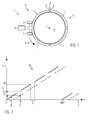
- the absolute value encoder 1 can have an evaluation unit 2, which can be connected in signal-transmitting manner to a first and a second sensor 3, 4. Furthermore, the absolute value encoder 1 can comprise at least one material measure 5.
- the measuring graduation 5 can be fastened to a body 6 whose absolute position P is determined with reference to the absolute value transmitter 1 or with reference to one of the two sensors 3, 4 shall be.
- absolute positions P encoded as measurement position values in the material measure 5 are read out by at least one of the sensors 3, 4 and the absolute position P is derived from the measurement position values.
- the measuring graduation 5 is fastened to a circular-cylindrical body 6.
- the body 6 may be formed as a hub or shaft of a wind turbine and may be, for example, the rotor hub or a shaft driving a generator.
- the absolute value encoder 1 according to the invention can also be used with other shafts, hubs or other shaped and possibly not only rotationally moving bodies 6.
- the material measure 5 can be arranged along a measurement path M, wherein the measurement path M in the exemplary embodiment illustrated here runs parallel to a circumferential direction U on a lateral surface of the body 6.
- the absolute value encoder 1 is thus shown as a rotary encoder.
- the absolute value encoder 1 can also determine absolute positions P of translationally moving bodies 6. Combinations of translational and rotational movements of the body 6 with respect to the absolute value transmitter 1 or relative to its sensors 3, 4 can determine the absolute value encoder 1.
- the material measure 5 can be arranged along an arbitrarily predetermined measurement path M.
- the material measure 5 can comprise a plurality of integral parts 7 which can be arranged separately on the body 6 or along the measurement path M.
- the material measure 5 can comprise a plurality of integral parts 7 which can be arranged separately on the body 6 or along the measurement path M.
- measuring scales 5 can be mounted on bodies 6, even if the body 6 is relatively large.
- a shaft for the generator of the windmill may have a diameter of up to one meter or more. Individual parts 7 of the material measure 5 can therefore possibly be easily attached by a single installer on the jacket of the shaft.
- the material measure 5 comprises, for example, four parts 7 which are arranged one behind the other along the measurement path M so that the body 6 is essentially surrounded in its circumferential direction U by the parts 7 forming the material measure 5.
- the parts 7 can have the coding of the absolute position P of the body 6, which can be scanned by the two sensors 3, 4.
- the coding may have the measurement position values that may assume discrete values.
- ends 8 of the parts 7 along the measuring path M or in the circumferential direction U can be arranged abutting or spaced from each other.
- the material measure 5 can also be made of several parts 7, which are integrally connected to one another.
- the absolute position P of the body 6 between two adjacent parts 7 or between the mutually facing ends 8 of two parts 7 is not represented as expected by measuring position values.
- the measurement position values in the region of the adjoining ends 8 of two codings of the parts 7 can have an unexpectedly large difference to one another, which does not represent the true, physical distance of the encoded measurement position values in the region of the adjacent ends 8 from one another. This difference can lead to an unexpected jump of the coding.
- the coding may be interrupted at least between the adjacent but spaced-apart ends 8. Such a gap in the coding can for example be caused by ends 8 of two parts 7, which are arranged at a distance from each other. It may also happen that the parts 7 are not or not properly coded in the region of the ends 8. Both the difference not representing the true distance and the gap can be detected by the absolute value encoder 1 as a discontinuity 9 in the coding.
- the sensors 3, 4 can be arranged along the measuring path M so that at least one of the two sensors 3, 4 always has valid measuring position values outside the discontinuity 9 of the material measure 5 can lose weight.
- the sensors 3, 4 along the measuring path M at least so far apart from each other be arranged so that the distance of the sensors 3, 4 to each other at least the geometric dimensions of the discontinuity 9 or the true distance along the measuring path M.
- the distance of the sensors 3, 4 from one another may be greater than the geometric dimensions of the discontinuity 9.
- the distance between the two sensors 3, 4 can be predetermined or determined during commissioning and be known in the absolute encoder 1.
- the measuring standard 5 can alternatively consist of a single piece, which can be arranged along the measuring path M and, for example, wound around the body 6.
- the two ends 8 such a material measure 5 along the measuring path M be arranged opposite to each other.
- This material measure 5 can thus have a continuous coding, which is arranged in a single coding section along the measuring path M and interrupted at only one point by the discontinuity 9.
- each of the parts 7 can have such a coding section in which the absolute position P is clearly coded.
- the parts 7 can be coded identically, so that the absolute position P can be clearly established within each of the parts 7.
- the amount of measurement position values of each part 7 can be identical.
- the absolute position of the body 6 over several parts 7 can be determined by determining the discontinuities 9 that have occurred during a movement of the body 6. Further, the parts 7 may include individual identification data. Alternatively, the parts 7 may be coded so that they represent a continuous encoded absolute position P except for the discontinuities 9.
- Fig. 2 shows measured position values W taken by the sensors 3, 4 of the absolute value transmitter 1 of the exemplary embodiment of FIG Fig. 1 ,
- Fig. 2 In the Fig. 2 are possible measuring position values W of the rotary encoder 1 of the embodiment of Fig. 1 represented in a coordinate system. Recorded valid measurement position values W of the sensor 3 are shown as solid and the sensor 4 as dashed sections. The actual physical absolute position P of the shaft 6 is plotted on the X axis of the coordinate system and the derived absolute position values L on the Y axis. In the illustration shown, the sensor 3 passes over five parts 7 of the measuring standard 5 of the exemplary embodiment of FIG Fig. 1 , This corresponds to a rotation of the body 6 about its longitudinal axis Z by about 450 °.
- the determination of the absolute position values L on the basis of the determined measurement position values W is shown by way of example at two support points 10, 11.
- the sensor 3 is located above one of the parts 7 or via its coding section.
- the measurement position value W can be uniquely assigned to the associated absolute position value L.
- the body 6 is further rotated, so that the sensor 3 is arranged above a discontinuity 9 formed as a gap and can not read off any valid measurement position values W from the material measure 5.
- the second sensor 4 is above the Coding section of read by the sensor 3 read before rotation part 7 and provides a valid measurement position value W.
- the measured position value W recorded at the support point 11 is converted into a provisional absolute position value L, which is then offset to determine the true absolute position value L with respect to the sensor 3 A is added.
- the offset value A corresponds to the distance between the two sensors 3, 4 relative to one another along the measurement path M and can be stored in absolute position values L or measurement position values W in the absolute value encoder 1.
- the measurement position values W of the sensors 3, 4 lie here in each case on a straight line. This means that the ends of the coding sections of two parts 7 are coded according to their true, physical distance from each other. The discontinuity 9 thus arises here exclusively by the absence of measurement position values W in the gap between the parts 7.
- the difference of the coded measuring position values W in the region of the ends 8 of the successive parts 7 can also be greater or smaller than the true distance, which leads to a discontinuity.
- the individual sections of the measurement position values W assigned to one of the parts 7 would in such a case not be aligned with one another on a straight line, but would be arranged offset parallel to this straight line. At least in such a case, a training run for learning the relation between the determined measurement position values W and the absolute position values L and the absolute positions P would be performed.
- the length of the discontinuity 9, for example the gap, along the measuring path M can likewise vary, which in addition can lead to a shift in the linear sections representing the measuring position values W along the straight line.
- Other sources of error such as local stretching or twisting of the measuring scale 5 during assembly or environmental influences, may influence the position or orientation of the sections of valid measuring position values W or the size of the discontinuity 9.
- the plausibility of the measurement position values W of one of the sensors 3, 4 can be determined. If the measurement position values W of one sensor 3, 4 are not plausible, for example invalid or completely missing, then the measurement position values W of the other sensor 4, 3 can be used and linked to the offset value A. Alternatively or additionally, measurement position values W of one of the sensors 3, 4 can only be used for a predetermined amount of measurement position values W are evaluated. Outside this set of measurement position values W, the sampled measurement position values W of the other sensor 4, 3 can be used.
- Fig. 3 shows a further embodiment, wherein for elements that in function and / or structure of the elements of the embodiment of Fig. 1 or 2 correspond, the same reference numerals are used. For brevity, only the differences from the embodiments of the Fig. 1 and 2 received.
- Fig. 3 are measured position values W, wherein the parts 7 of the embodiment of the Fig. 1 all are coded identically.
- the absolute value encoder 1 For determining the absolute position value L, it is necessary for the absolute value encoder 1 to have information about the respectively sampled part 7. Since the parts 7 are coded identically, the absolute value encoder 1 can determine this information, for example, by counting the discontinuities 9 that have occurred. In the case of a transition from one part 7 to another part 7, eg after a gap D1, the coding jumps at a discontinuity S1 by, for example, 1000 measuring position values or also units.
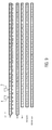
- Fig. 4 shows a schematic representation of an embodiment of a method for determining absolute positions P by means of measurement position values W, with an absolute value encoder 1 according to the embodiments of the Fig. 1 and 2 is formed.
- the discontinuities 9 of the Fig. 4 have jump gaps S in addition to gaps D.
- the distance between the two sensors 3, 4 is in the exemplary embodiment shown seven measurement position values W or units, so that the offset value A is equal to seven.
- the sensors 3, 4 are arranged at measuring points M3, M4 with respect to the material measure 5.
- absolute values L are plotted.
- the coding of the material measure 5 with four parts 7, 7 ', 7 ", 7'” is shown, each having a coding section A, B, C, D.
- Each of the discontinuities 9, 9 ', 9" comprises a gap D1, D2, D3, through which the parts 7 , 7 ', 7 ", 7"' spaced apart along the measuring path M are arranged.
- the gap D1 is three units, the gap D2 two units and the gap D3 four units. Further, the discontinuity 9 is formed with a jump in size of minus two units. The Discontinuity 9 'includes a jump of four units and the discontinuity 9 "of minus three units.
- the coding sections A, B, C, D comprise different sets of measuring position values W, the part 7 starting with a measuring position value W of 1, which is arranged at a position K1. In position K2 following position K1, the measuring position value W is equal to two. Successive positions Kn are provided with successive measurement values W for all parts 7, 7 ', 7 ", 7"'.
- the measured position values W detected by the two sensors 3, 4 are shown when the measuring scale 5 is passed over. In the area of the gaps D1, D2, D3, the sensors 3, 4 do not detect any measured position values W, since these are not present here. However, due to the distance of seven units between the sensors 3, 4, the measured position values W of the two sensors 3, 4 offset by the offset value of seven, so that gaps D1, D2, D3 in the sampled measurement position values X3 of measurement position values W in the Line X4 are bridged.
- the absolute position P of the body 6 should be determined here with reference to the sensor 3. If the sensor 3 passes over the coding section A, then the measuring position values W, X3 taken from it can be directly assigned to the absolute position values L or correspond to them.
- the part 7 is a first or reference part.
- the sensor 3 does not perceive any measurement position values W, so that the measurement position values L are determined from the measured position values W, X4 of the sensor 4, to which the offset value A is added.
- This position correction can also be carried out at the position K11 of the coding K.
- the value thus calculated is here designated W, X4, K11.
- the compensation factor E is composed of the measured position value W, X4, K11, the offset value A and the measuring position value W valid at the point K11 by the sensor 4, wherein the value W, X, K11 is added to the offset value A and the measurement position value W of the point K11 is subtracted therefrom.
- the removed measurement position value W, X4 of the sensor 4 is to be linked additively with the offset value A and with the compensation factor E.
- This can also be done in K21.
- the measured position value W, X3 picked up by the sensor 3 can be additively linked to the offset value A, the compensation factor E and to a further compensation factor E '.
- the further compensation factor E ' can be constructed analogously to the factor E, wherein the respective measurement position values W are related to the current section 7 "of the material measure 5 - the measurement position value W, X4, K21 taken at the point K21 by the sensor 4 becomes the offset value A additive linked and subtracted the value of the point K21 herebefore.
- the measured position value W, X4 removed by the sensor 4 can be additively linked to the offset value A. Furthermore, the two compensation factors E, E 'are linked to the measurement position value W, X4.
- the measurement position values W, X3, X4 sampled by the sensors 3, 4 from further parts 7 of the material measure 5 can also be corrected in an analogue manner and converted into absolute position values L.
- Fig. 5 shows a schematic representation of an embodiment of a method for determining absolute position P on the basis of measurement position values W, in which the parts 7 of the material measure 5 as in Fig. 3 are shown identically encoded.
- the distance A of the two sensors 3, 4 to each other here is 8 measurement position values W or units.
- the respective parts 7, 7 ', 7 “, 7'” are arranged separated from one another by discontinuities 9, 9 ', 9 "and in particular by gaps D1, D2, D3 along the measuring path M.
- the gap D1 is two units
- the gap D2 is four
- the gap D3 is three units
- the transition from one part 7, 7 ', 7 ", 7" to another part 7, 7', 7 ", 7 '” is minus 10 units
- X4 show again taken measuring position values W.
- the line L over is shown again by way of example a calculation method used for the position correction and the determination of the absolute position values L on the basis of the taken measuring position values X3, X4 Fig. 4 Calculation rule shown can also in the embodiment of Fig. 5 Find application.
- Fig. 6 shows a further embodiment of the absolute value encoder 1 according to the invention, wherein for elements that in function and / or structure of the elements of the embodiments of the Fig. 1 to 5 correspond, the same reference numerals are used. For brevity, only the differences from the embodiments of the Fig. 1 to 5 received.
- Fig. 6 only part 7 of the measuring standard 5 is shown mounted on the body 6. Other parts 7 may already be mounted or later still be mounted. Alternatively, the material measure 5 can comprise only a part 7. The position shown of the part 7 is shown mounted incorrectly perpendicular to the measuring path M or to the body 6, whereby the read out measurement position values W can no longer be assigned to the absolute position P without further ado.
- the part 7 is arranged radially offset from the longitudinal axis Z of the body 6.
- Such a task may also arise without problems associated with discontinuity 9.
- the absolute value encoder 1 can be used.
- the part 7 can be moved past the sensors 3, 4 along the measuring path M and, to determine the type and size of the incorrect assembly, they both simultaneously remove the measured position values W from the part 7 and forward them to the evaluation unit 2.
- the measured measurement position values W of the two sensors 3, 4 can be compared, resulting in a representative of the type and size of incorrect assembly error signal F, which in the Fig. 7 is shown.
- the Fig. 7 shows processed measurement position values W and W ", which each originate from one of the sensors 3, 4.
- the measurement position values W 'of the sensor 4 are corrected by linking with the offset value A.
- the offset value A can be added to the measurement position value W determined by the sensor 4 If measuring position values W of different parts 7 are used, then the compensation factor K which takes account of the discontinuity 9 must also be used for the position correction, and this position correction of the measurement position values W, W 'can be compared directly with one another.
- the Fig. 7 the deviation of the determined measurement position values W, W 'from an ideal course of expected measurement values to be measured is shown. It can be seen that the position-corrected measuring position values W, W 'are close to each other at the beginning, ie at 0 °, for example. These measurement position values W ', W' can be recorded in the region of one of the ends 8 of the part 7, which is arranged very close to the measurement path M. In their course, these measured position values W, W 'move away from each other up to a maximum distance of about 90 °, in order then to be close to each other again at about 180 °.
- the course shown here by way of example corresponds to the radial offset of part 7 of Fig.
- the resulting shape curves of the deviation of the specific measurement position values W, W 'from the ideal measurement position values and also the resulting measurement signal and fault signal F can be characteristic of the respective faulty assembly.
- the determined curves represent a user or fitter or evaluated automatically by the absolute encoder 1.
- Fig. 8 shows a further embodiment of the absolute value encoder 1 according to the invention, wherein for elements which correspond in function and / or construction to the elements of the embodiments of the previous figures, the same reference numerals are used. For brevity, only the differences from the embodiments of the previous figures will be discussed.
- Fig. 8 shows the absolute value encoder 1 schematically with various functional units.
- the functional units can be designed as separate elements or as functions of a single element, for example the evaluation unit 2. Alternatively or additionally, each of the functional units can be implemented as software.
- the two sensors 3, 4 may be signal transmitting connected to an absolute position value output unit 12 of the absolute value encoder 1, wherein the Measurement position values W of one of the sensors 3, 4, for example of the first sensor 3, can be passed unchanged to the absolute position value output unit 12.
- the second sensor 4, which is arranged at a distance from the sensor 3, can first be connected in a signal-transmitting manner to a position correction unit 13 and transmit the measurement position values W determined by it to this unit 13.
- the position correction unit 13 may be data-transmitting connected to a memory unit 14, in which the offset value A can be stored permanently.
- the compensator 15 can be provided, which combines the determined measuring position values W at least with the offset value A and adds them together, for example. As a result of this linkage, the position correction unit 13 can output the position-corrected measurement position values W of the sensor 4 to the absolute position value output unit 12.
- the absolute position value output unit 12 can automatically decide which of the supplied measurement position values W should be used to determine the absolute position P.
- an inspection unit not shown here, can be arranged between the absolute position value output unit 12 and the sensors 3, 4, to which the measuring position values W of both sensors 3, 4 are fed and which only one of the two measuring position values W after their testing to determine the absolute position P at the Absolute level output unit 12 outputs.
- a further sensor 3 'can be provided.
- the function of the further sensor 3 'can be fulfilled by one of the sensors 3, 4. If one of the discontinuities 9 passes the further sensor 3 ', it recognizes the passing discontinuity 9 and outputs a signal to a nonvolatile memory 16.
- the passage of the discontinuities 9 can be documented. As a result, for example, the function of a so-called multi-turn encoder can be displayed. Further, each of the sensors 3, 4 just scanned parts 7 can be identified.
- the further sensor 3 can be used as a generator and, for example, as a so-called microgenerator may be formed.
- the generator can generate a signal even in the switched-off state of the absolute encoder 1, which can be documented in the nonvolatile memory 16.
- the discontinuity 9, in particular the gap D1, D2, D3, may include at least one microgenerator actuating element, for example a magnet.
- the test unit 17, the measurement position values W of both sensors 3, 4 are supplied on the input side.
- a representative of the type and size of incorrect assembly error signal F can be generated and then output.
- the determined measurement position values W can be compared with ideal measurement position values in the test unit 17.
- the representative signal as in the description of the embodiment of Fig. 7 can be generated represented.
- the determined and positionally corrected measurement position values W can be evaluated directly or relative velocities between the sensors 3, 4 and the body 6 along the measurement path M derived from the measurement position values W of the two sensors 3, 4 can be determined.
- the determined speeds can also be used to determine the incorrect assembly F representing the signal and, for this purpose, for example, be subtracted from each other.
- the test unit 17 can be signal-transmitting connected to the compensator 15 or the absolute position value output unit 12, so that 5 may possibly be compensated by the incorrect assembly of the material measure corresponding inaccuracies of the absolute position determination.
- Fig. 9 shows an embodiment of a method for determining the incorrect assembly of the material measure 5.
- the measuring scale 5 is misassembled in a central area and bulges, for example, from the measuring path M in the direction of the sensors 3, 4.
- This embodiment is similar to the embodiment of the Fig. 6 ,
- the material measure 5 is arranged along the measuring path M.
- the position of the measuring standard 5 deviates from the measuring path M perpendicular to this.
- measuring position values W adjacent to one another appear closer to one another from the perspective of the sensors 3, 4, which can lead to a faster change in the measured position values W in the range of the positions K9 to K20 during operation and is represented by the omission of measuring position values W.
- the distance of the sensors 3, 4 is in this embodiment only 2 units.
- the measured position values W sampled by the sensor 3 are shown
- corr is position corrected and taken by the sensor 4 Measurement position values W, X4 shown.
- the offset value A is added to these.
- the position-corrected measurement position values W, X4 sampled by the sensor 4 are subtracted from the measurement position values W, X3 sampled by the sensor 3.
- the difference of the position-corrected measurement position values W is constant and in particular 0.
- this difference deviates from the constant value from where the difference at the position K16 reaches its maximum. Based on the shape of the resulting from the difference values error function can be determined both size and shape of the incorrect assembly.
Abstract
Description
Die Erfindung betrifft einen Absolutwertgeber zur Bestimmung einer Absolutlage eines Körpers relativ zum Absolutwertgeber, mit wenigstens einer sich entlang eines Messweges erstreckenden Maßverkörperung, die eine Kodierung der Absolutlage mit Messlagewerten aufweist, und mit wenigstens zwei Sensoren, durch die im Betrieb die Kodierung abtastbar ist.The invention relates to an absolute value sensor for determining an absolute position of a body relative to the absolute value encoder, comprising at least one measuring standard extending along a measuring path, which has a coding of the absolute position with measured position values, and at least two sensors, by which the coding can be scanned during operation.
Ferner betrifft die Erfindung ein Verfahren zur Bestimmung einer Absolutlage zweier Körper relativ zueinander, bei dem eine Absolutlagewerte enthaltende Kodierung der Absolutlage mehrfach abgetastet und ein für die Absolutlage repräsentatives Absolutlagesignal erzeugt und ausgegeben wird.Furthermore, the invention relates to a method for determining an absolute position of two bodies relative to one another, in which a coding of the absolute position containing absolute position values is scanned several times and an absolute position signal representative of the absolute position is generated and output.
Absolutwertgeber mit Maßverkörperungen sind allgemein bekannt. Physikalische oder körperliche Absolutlagen werden durch diese Absolutwertgeber ermittelt und als Absolutlagewerte dargestellt. Um an jeder Stelle entlang eines Messweges die Absolutlage bestimmen zu können, sind die Maßverkörperungen lückenlos ausgebildet. Beispielsweise werden ringförmige Maßverkörperungen auf Wellen aufgesetzt, um deren Drehlage absolut bestimmen zu können. Eine solche Maßverkörperung umfasst in der Regel eine einzige durchgehende Kodierung. Absolutwertgeber unterscheiden sich von Inkrementalgebern dadurch, dass sie die Absolutlage des Körpers beim Einschalten, sobald sie mit Energie versorgt sind, an einer Ausgangsschnittstelle zur Verfügung stellen können. Die Erfassung erfolgt vorzugsweise unmittelbar durch Abtasten der Kodierung der Maßverkörperung. Ein Inkrementalgeber stellt dagegen nicht ein für die Absolutlage, sondern ein für eine Lageänderung repräsentatives Signal an einer Ausgangsschnittstelle bereit.Absolute encoders with dimensional standards are well known. Physical or physical absolute positions are determined by these absolute encoders and displayed as absolute position values. In order to be able to determine the absolute position at any point along a measuring path, the measuring graduations are formed without gaps. For example, annular measuring graduations are placed on shafts in order to be able to determine their rotational position absolutely. Such a material measure usually includes a single continuous coding. Absolute encoders differ from incremental encoders in that they can provide the absolute state of the body at power-up as soon as it is energized at an output interface. The detection is preferably carried out directly by scanning the coding of the material measure. In contrast, an incremental encoder does not provide a signal representative of a position change at an output interface, but rather for the absolute position.
Insbesondere bei der Absolutlagebestimmung von großen Körpern, beispielsweise von einer einen Generator einer Windkraftanlage antreibenden Welle, sind einteilige Maßverkörperungen unpraktisch, da sie sehr groß und nur mit viel Aufwand herzustellen und zu montieren sind. Ferner können Maßabweichungen der Welle mit einer einteiligen Maßverkörperung nicht ohne Weiteres ausgeglichen werden.In particular, in the absolute position determination of large bodies, for example by a generator of a wind turbine driving wave, one-piece dimensional standards are impractical, since they are very large and only with great effort to manufacture and assemble. Furthermore, dimensional deviations of the shaft with a one-piece material measure can not be compensated easily.
Des Weiteren sind Maßverkörperungen für unregelmäßige Messwege schwierig herzustellen. Um beispielsweise Bewegungen des Körpers entlang eines Messweges, der aus translatorischen und/oder rotatorischen Bewegungen zusammengesetzt ist, herzustellen, müsste eine entsprechend und womöglich unregelmäßig geformte Maßverkörperung einteilig hergestellt werden. Eine Fertigung einer solchen Maßverkörperung ist jedoch sehr anfällig für Fertigungstoleranzen.Furthermore, measuring scales for irregular measuring paths are difficult to produce. To produce, for example, movements of the body along a measuring path which is composed of translatory and / or rotational movements, a correspondingly and possibly irregularly shaped one would have to be produced Measuring standard be made in one piece. However, a production of such a material measure is very susceptible to manufacturing tolerances.
Es ist daher die Aufgabe der Erfindung, die bekannten Absolutwertgeber so zu verbessern, dass sie flexibler eingesetzt werden können und geringere Anforderungen an die Anbringung und den Aufbau der Maßverkörperung stellen.It is therefore an object of the invention to improve the known absolute value encoder so that they can be used flexibly and make lower demands on the attachment and the structure of the material measure.
Für den eingangs genannten Absolutwertgeber wird die Aufgabe dadurch gelöst, dass die Kodierung in ihrem Verlauf wenigstens eine Diskontinuität aufweist.For the abovementioned absolute value encoder, the object is achieved in that the coding has at least one discontinuity in its course.
Für das eingangs genannte Verfahren wird die Aufgabe dadurch gelöst, dass die Kodierung in ihrem Verlauf eine Diskontinuität aufweist und zur Bestimmung der Absolutlage innerhalb der Diskontinuität einer der Messlagewerte der Kodierung außerhalb der Diskontinuität mit einem Offsetwert verknüpft wird.For the method mentioned in the introduction, the object is achieved in that the coding has a discontinuity in its course and is linked to an offset value for determining the absolute position within the discontinuity of one of the measurement position values of the coding outside the discontinuity.
Die erfindungsgemäße Lösung ist konstruktiv einfach und hat den Vorteil, dass Diskontinuitäten der Kodierung der Maßverkörperung eine flexiblere Montage der Maßverkörperung erlauben und durch den Absolutwertgeber überbrückbar sind und dieser auch im Bereich der Diskontinuitäten gültige Messlagewerte liefern kann. Dies ist sogar möglich, wenn die kodierte Absolutlage im Bereich der Diskontinuität eine Absolutlage des Körpers nicht repräsentiert bzw. die Kodierung im Bereich der Diskontinuität unstetig oder lückenhaft ist.The solution according to the invention is structurally simple and has the advantage that discontinuities of the coding of the material measure allow a more flexible assembly of the measuring standard and can be bridged by the absolute value transmitter and this can also deliver valid measuring position values in the area of the discontinuities. This is even possible if the coded absolute position in the area of the discontinuity does not represent an absolute position of the body or the coding in the area of the discontinuity is discontinuous or incomplete.
Die erfindungsgemäße Lösung kann durch verschiedene, jeweils für sich vorteilhafte, beliebig miteinander kombinierbare Ausgestaltungsformen weiter verbessert werden. Auf diese Ausgestaltungen und die mit ihnen verbundenen Vorteile wird im Folgenden eingegangen.The solution according to the invention can be further improved by various, each advantageous, arbitrarily combinable embodiments. These refinements and the advantages associated with them will be discussed below.
So kann in einer Weiterbildung die Diskontinuität eine Lücke in der Maßverkörperung und/oder eine Sprungstelle in der Kodierung umfassen. Lücken in der Maßverkörperung ermöglichen einen Längen- oder Positionsausgleich, in dem die Kodierung über eine insbesondere unbekannte Länge unterbrochen ist. Sie erlauben es, die Maßverkörperung an die unbekannte Geometrie des Körpers anzupassen, dessen Lage bestimmt werden soll. Hierzu kann die Maßverkörperung flexibel und womöglich sogar entlang des Messweges elastisch verformbar aus-gestaltet sein. Ausdehnungen des Messweges können durch die Lücke kompensiert werden, selbst wenn die Maßverkörperung zumindest entlang des Messweges im Wesentlichen unelastisch ausgeformt ist. Ferner kann die Lücke auch durch Beschädigung oder durch Fehlstellen hervorgerufen werden. Sprungstellen können zum Beispiel durch eine Fehlmontage der Maßverkörperung entlang des Messweges entstehen. Sie entstehen auch, wenn Abschnitte mit unterschiedlichen Kodierungen aneinanderstoßen.Thus, in a further development, the discontinuity may include a gap in the material measure and / or a discontinuity in the coding. Gaps in the material measure allow a length or position compensation in which the coding is interrupted over a particular unknown length. They make it possible to adapt the material measure to the unknown geometry of the body whose position is to be determined. For this purpose, the material measure can be designed to be flexible and possibly even elastically deformable along the measurement path. Extensions of the measuring path can be compensated by the gap, even if the material measure is at least substantially inelastic in shape along the measuring path. Furthermore, the gap can also be caused by damage or by defects. Jumps can be through, for example Incorrect assembly of the material measure along the measuring path arise. They also arise when sections of different codings collide.
Die Kodierung kann gemäß einer weiteren vorteilhaften Ausgestaltung aus mehreren Kodierabschnitten zusammengesetzt sein, die entlang des Messweges hintereinander angeordnet sind und von denen wenigstens zwei durch die wenigstens eine Diskontinuität voneinander getrennt sind. Die Kodierung aufeinanderfolgender Kodierabschnitte kann die Absolutlage im Wesentlichen durchgehend wiedergeben, d.h. aufeinanderfolgende Kodierabschnitte weisen keine Sprungstele an der Diskontinuität auf, so dass der Absolutwertgeber zumindest im Betrieb jederzeit die Absolutlage erkennen kann.The coding can be composed according to a further advantageous embodiment of a plurality of coding sections, which are arranged along the measuring path in a row and of which at least two are separated from each other by the at least one discontinuity. The coding of successive coding sections can substantially completely reflect the absolute position, i. successive coding sections have no jump stops at the discontinuity, so that the absolute value encoder can detect the absolute position at any time, at least during operation.
Damit die Kodierung einfach und beispielsweise aus einem Bausatzsystem zusammengesetzt werden kann, können die Kodierabschnitte alternativ identisch kodiert sein. Beispielsweise können mehrere oder alle Kodierabschnitte der Maßverkörperung bei einem minimalen Messlagewert von beispielsweise Null beginnen und bei einem identischen Maximalwert enden. Beim Zusammensetzen der Kodierung braucht die Reihenfolge der Kodierabschnitte somit nicht berücksichtigt zu werden. Zwischen den Kodierabschnitten treten an der Diskontinuität Sprungstellen auf, die durch den Übergang vom minimalen zum maximalen Messlagewert oder umgekehrt hervorgerufen werden.So that the coding can be composed simply and, for example, from a kit system, the coding sections can alternatively be coded identically. For example, several or all coding sections of the material measure can start at a minimum measuring position value of, for example, zero and end at an identical maximum value. When assembling the coding, therefore, the order of the coding sections need not be considered. Between the coding sections, jump discontinuities occur at the discontinuity, which are caused by the transition from the minimum to the maximum measurement position value or vice versa.
Passiert eine Diskontinuität zwischen zwei Kodierabschnitten einen der Sensoren des Absolutwertgebers, kann es vorteilhaft sein, wenn der Absolutwertgeber dieses Passieren der Diskontinuität erfasst und wenigstens zeitweise speichert. Damit ist gewährleistet, dass der Absolutwertgeber die Absolutlage nicht nur innerhalb des Kodierabschnittes, sondern in allen Kodierabschnitten bestimmen kann, auch wenn zumindest einige der Kodierabschnitte identisch kodiert sind.If a discontinuity between two coding sections passes one of the sensors of the absolute value encoder, it may be advantageous if the absolute value encoder detects this passing of the discontinuity and at least temporarily stores it. This ensures that the absolute value encoder can determine the absolute position not only within the coding section but in all coding sections, even if at least some of the coding sections are coded identically.
Insbesondere kann die Diskontinuität bei einem Drehgeber als ein Kodierelement zur Erfassung der Anzahl der vollen Umdrehungen ausgestaltet sein und genutzt werden. Bei dieser Ausgestaltung erhält man einen Multiturn-Drehgeber, dessen Absolutsignal aus einer Singleturn-Position und einer Multiturn-Position zusammengesetzt ist. In der Singleturn-Position ist die Position innerhalb einer vollen Umdrehung codiert und sie wird mithilfe der Kodierabschnitte der Maßverkörperung erfasst. Die Multiturn-Position erfasst die Anzahl der vollen Umdrehungen, gegebenenfalls unter Berücksichtigung der Drehrichtung.In particular, the discontinuity in a rotary encoder can be configured and used as a coding element for detecting the number of full revolutions. In this embodiment, one obtains a multi-turn encoder whose absolute signal is composed of a single-turn position and a multi-turn position. In the singleturn position, the position is coded within a full revolution and it is detected by means of the coding sections of the material measure. The multi-turn position records the number of full revolutions, if necessary taking into account the direction of rotation.
Um die Maßverkörperung möglichst einfach zusammensetzen zu können, können die Kodierabschnitte als separate einstückige Teile der Maßverkörperung ausgeformt sein. Jedes der Teile kann insbesondere genau einen Kodierabschnitt aufweisen, so dass die Diskontinuität an wenigstens einem Übergang zwischen zwei Teilen bzw. Kodierabschnitten angeordnet ist. Die Teile können so dimensioniert und ausgestaltet sein, dass sie durch einen Monteur einfach entlang des Messweges angeordnet und am Körper befestigt werden können. Große oder unregelmäßige Messwege können so einfach und ohne großen Aufwand durch mehrere Teile abgebildet werden.In order to assemble the material measure as simply as possible, the coding can be formed as a separate one-piece parts of the material measure. In particular, each of the parts may have exactly one coding section, so that the discontinuity is arranged at at least one transition between two parts or coding sections. The parts can be dimensioned and designed so that they can be easily arranged by a fitter along the measuring path and attached to the body. Large or irregular measuring paths can be mapped easily and without great effort by several parts.
Der Absolutwertgeber kann einen Kompensator zur Kompensation der Diskontinuität aufweisen, wobei der Kompensator signalübertragend eingangsseitig mit den Sensoren und ausgangsseitig mit einer Absolutlagewertausgabeeinheit des Absolutwertgebers verbunden sein kann. An einem Signalausgang der Absolutlagewertausgabeeinheit können die von den Messwerten abgeleiteten und die Absolutlage repräsentierenden Absolutlagewerte anliegen. Die Absolutlagewerte können im Absolutlagesignal enthalten über den Signalausgang ausgebbar sein. Im Kompensator können die jeweils von einem der Sensoren abgetasteten Messlagewerte mit einem Kompensationsfaktor und gegebenenfalls dem Offsetwert verknüpft werden, wodurch durch die Diskontinuität erzeugte Abweichungen der Messlagewerte von den Absolutlagen ausgleichbar sind. Der Kompensationsfaktor kann für jeden Kodierabschnitt individuell, beispielsweise bei einem Trainingslauf während der Inbetriebnahme des Absolutwertgebers, ermittelt werden und von der Größe der Diskontinuität abhängen.The absolute value encoder may have a compensator for compensating the discontinuity, wherein the compensator signal-transmitting input side may be connected to the sensors and the output side with an absolute position value output unit of the absolute value encoder. The absolute position values derived from the measured values and representing the absolute position can be present at a signal output of the absolute position value output unit. The absolute position values can be output in the absolute position signal via the signal output. In the compensator, the respective measured position values sampled by one of the sensors can be linked to a compensation factor and, if appropriate, to the offset value, whereby deviations of the measurement position values from the absolute positions produced by the discontinuity can be compensated. The compensation factor can be determined individually for each coding section, for example during a training run during the commissioning of the absolute value encoder, and depend on the size of the discontinuity.
Werden die Teile entlang des Messweges so montiert, dass diese beispielsweise nicht aneinanderstoßend, sondern mit einem die Lücke bildenden Abstand zueinander am Körper befestigt werden, kann der Absolutwertgeber dennoch die Absolutlage bestimmen. Hierzu können die Sensoren entlang der Maßverkörperung bzw. des Messweges beabstandet zueinander angeordnet sein. Der Abstand der Sensoren zueinander kann vorteilhaft zumindest der Ausdehnung der Lücke entsprechen. Besonders vorteilhaft ist, wenn der Abstand der Sensoren zueinander entlang des Messweges größer als die Ausdehnung der Lücke ist. Somit ist gewährleistet, dass wenigstens einer der Sensoren jederzeit gültige Messwerte eines Kodierabschnittes ablesen kann. Fehlmontagen der Teile entlang des Messweges gefährden die Inbetriebnahme des Absolutwertgebers zumindest in gewissen Grenzen nicht. Ferner können Maßtoleranzen des Körpers, zum Beispiel ansonsten unakzeptable Toleranzen des Durchmessers der Welle, durch gezielten Einsatz der Lücken ausgeglichen werden. Die Länge der Lücke entlang des Messweges kann zum Ausgleich der Toleranzen variiert werden.If the parts are mounted along the measuring path in such a way that they are not fastened to one another, for example, but are fastened to one another with a gap forming the gap, the absolute value encoder can nevertheless determine the absolute position. For this purpose, the sensors can be arranged spaced apart from one another along the material measure or the measurement path. The distance of the sensors from each other can advantageously correspond at least to the extent of the gap. It is particularly advantageous if the distance of the sensors from each other along the measuring path is greater than the extent of the gap. This ensures that at least one of the sensors can read valid measured values of a coding section at any time. Incorrect assembly of the parts along the measuring path does not jeopardize the commissioning of the absolute encoder, at least within certain limits. Furthermore, dimensional tolerances of the body, for example, otherwise unacceptable tolerances of the diameter of the shaft, balanced by targeted use of the gaps become. The length of the gap along the measuring path can be varied to compensate for the tolerances.
Zur Kompensation der Diskontinuität kann die Kodierung beispielsweise gleichzeitig an einer ersten und einer zweiten Messstelle durch jeweils einen der Sensoren abgetastet werden, wobei die Messstellen entlang der die Kodierung tragenden Maßverkörperung voneinander beabstandet angeordnet sind. Der Abstand der Messstellen zueinander kann dabei durch den Abstand der Sensoren voneinander vorgegeben sein. Liefert einer der Sensoren ungültige Messlagewerte, kann die Position dieses Sensors mit Bezug auf den Körper anhand der durch den anderen Sensor bestimmten Messlagewerte ermittelt werden. Hierzu sind die von dem anderen Sensor ermittelten Messlagewerte mit dem Offsetwert und gegebenenfalls mit dem Kompensationsfaktor zu verknüpfen. Der Offsetwert kann dem Abstand der Messstellen bzw. der Sensoren zueinander entsprechen und in einer Speichereinheit des Absolutwertgebers abgelegt sein. Die Speichereinheit kann signalübertragend eingangsseitig mit zumindest einem der Sensoren und/oder ausgangsseitig mit einer Absolutlagewertausgabeeinheit des Absolutwertgebers verbunden sein kann. Solange zumindest einer der Sensoren gültige Messlagewerte von der Maßverkörperung abtastet, ist die Absolutlage des Körpers relativ zu jedem Sensor des Absolutwertgebers bestimmbar.To compensate for the discontinuity, the coding can be scanned, for example at the same time at a first and a second measuring point by one of the sensors, wherein the measuring points along the coding bearing dimensional standard are arranged spaced from each other. The distance between the measuring points to each other can be predetermined by the distance of the sensors from each other. If one of the sensors supplies invalid measurement position values, the position of this sensor with respect to the body can be determined on the basis of the measurement position values determined by the other sensor. For this purpose, the measurement position values determined by the other sensor are to be linked to the offset value and optionally to the compensation factor. The offset value may correspond to the distance of the measuring points or the sensors from each other and stored in a memory unit of the absolute value encoder. The memory unit can be connected on the input side with at least one of the sensors and / or on the output side with an absolute position value output unit of the absolute value transmitter. As long as at least one of the sensors scans valid measurement position values from the material measure, the absolute position of the body relative to each sensor of the absolute value transmitter can be determined.
Um zu entscheiden, welcher Sensor zur Bestimmung der Absolutlage abgefragt werden soll, können Messlagewerte der ersten Messstelle für eine vorbestimmte Menge von Messlagewerten verwendet werden. Für andere Messlagewerte der ersten Messstelle können Messlagewerte der zweiten Messstelle für die Bestimmung der Absolutlage verwendet werden. Beispielsweise kann der erste Sensor für Messlagewerte abgefragt werden, die in einem vorbestimmten Abstand von beispielsweise zehn Messlagewerten von der Diskontinuität angeordnet sind. Ist der erste Sensor näher als vorgegeben an der Diskontinuität, so werden die Messlagewerte des zweiten Sensors verwendet. Hierzu kann eine Umschalteinrichtung vorgesehen sein, welche in Abhängigkeit von dem von einem der wenigstens zwei Sensoren erfassten Messlagewert auf den wenigstens einen anderen Sensor umschaltet. Durch das Umschalten wird der Ausgang des anderen Sensors ausgewertet.In order to decide which sensor is to be interrogated to determine the absolute position, measuring position values of the first measuring point can be used for a predetermined set of measuring position values. For other measuring position values of the first measuring point, measuring position values of the second measuring point can be used to determine the absolute position. For example, the first sensor can be interrogated for measurement position values which are arranged at a predetermined distance from, for example, ten measurement position values from the discontinuity. If the first sensor is closer than predetermined at the discontinuity, the measurement position values of the second sensor are used. For this purpose, a switching device may be provided, which switches over to the at least one other sensor as a function of the measured position value detected by one of the at least two sensors. By switching the output of the other sensor is evaluated.
Alternativ oder zusätzlich kann die Plausibilität der Kodierung zumindest einer der Messstellen, beispielsweise der ersten Messstelle, geprüft werden. Basierend auf dem Ergebnis der Prüfung kann die Kodierung der jeweils anderen und beispielsweise der zweiten Messstelle zur Bestimmung der Absolutlage verwendet werden. Insbesondere im Bereich der Diskontinuität, aber auch bei Beschädigung der Maßverkörperung oder Fehlern in der Kodierung, können die kodierten Messlagewerte nicht plausibel sein. Diese nicht plausiblen Messlagewerte an der einen Messstelle beeinträchtigen die Bestimmung der des Absolutlage jedoch nicht, wenn an der anderen Messstelle plausible bzw. gültige Messlagewerte vorliegen.Alternatively or additionally, the plausibility of the coding of at least one of the measuring points, for example the first measuring point, can be checked. Based on the result of the test, the coding of the other and, for example, the second measuring point can be used to determine the absolute position. Especially in the area of discontinuity, but also in the case of damage to the material measure or errors in the coding, the coded measuring position values can not be plausible. However, these non-plausible measuring position values at one measuring point do not affect the determination of the absolute position if plausible or valid measuring position values are present at the other measuring point.
Falls der Körper im ausgeschalteten Zustand des Absolutwertgebers bewegt werden sollte, könnte der Absolutwertgeber die Absolutlage des Körpers verlieren und nach einer erneuten Inbetriebnahme nicht mehr richtig bestimmen, da der Absolutwertgeber zum Beispiel bei identisch ausgebildeten Kodierabschnitten nicht mehr bestimmen könnte, welcher Kodierabschnitt zur Bestimmung der Absolutlage aktuell durch die Sensoren abgetastet wird. Folglich kann der Absolutwertgeber in einer weiteren vorteilhaften Ausgestaltung einen Sensor umfassen, der ein Passieren von Diskontinuitäten auch im ausgeschalteten Zustand des Absolutwertgebers detektiert. Der Sensor kann signalübertragend mit einem nichtflüchtigen Speicher verbunden sein, der die Bewegung der Diskontinuität vorbei am Sensor und entlang des Messweges dokumentiert.If the body should be moved in the off state of the absolute encoder, the absolute value encoder could lose the absolute position of the body and not correctly determine after a restart, since the absolute encoder could not determine, for example, with identical coding sections, which coding section for determining the absolute position currently being scanned by the sensors. Consequently, in a further advantageous embodiment, the absolute value encoder can comprise a sensor which detects passage of discontinuities even when the absolute value transmitter is switched off. The sensor may be signal transmitting connected to a non-volatile memory, which documents the movement of the discontinuity past the sensor and along the measuring path.
Die Funktion dieses Sensors kann in einer weiteren vorteilhaften Ausgestaltung in einem der beiden Sensoren abgebildet sein. Alternativ kann der Sensor als ein separater Sensor ausgebildet sein. Insbesondere kann der Sensor einen Betriebsenergie für den nichtflüchtigen Speicher erzeugenden Generator umfassen und ein Signal an den nichtflüchtigen Speicher ausgeben, wenn er die Diskontinuität passiert. Beim Passieren der Diskontinuität kann ein Speicherwert in der nichtflüchtigen Speichereinheit geändert werden. Die im Signal enthaltene Energie kann genutzt werden, um Werte des nichtflüchtigen Speichers zu ändern, auch wenn der Absolutlagewertgeber ausgeschaltet ist. In der Diskontinuität und insbesondere in der Lücke kann zumindest ein den Generator antreibendes Bauelement, beispielsweise ein Magnet, angeordnet sein.The function of this sensor can be mapped in one of the two sensors in a further advantageous embodiment. Alternatively, the sensor may be formed as a separate sensor. In particular, the sensor may include an operating energy for the nonvolatile memory generating generator and output a signal to the nonvolatile memory as it passes the discontinuity. When passing the discontinuity, a memory value in the nonvolatile memory unit can be changed. The energy contained in the signal can be used to change values of the nonvolatile memory even when the absolute position sensor is switched off. In the discontinuity and in particular in the gap, at least one component driving the generator, for example a magnet, can be arranged.
Auch eine Fehlmontage der Maßverkörperung senkrecht zum Messweg kann zu einer ungenau bestimmten Absolutlage führen. Ist die Maßverkörperung beispielsweise an einem kreiszylindrischen Körper, etwa einer Welle oder einer Nabe, angebracht, so kann es vorkommen, dass die Maßverkörperung im Vergleich zu einer optimalen Lage auf dem Messweg radial versetzt angeordnet ist. Bei einem flächigen oder gewölbten Körper kann die fehlmontierte Maßverkörperung senkrecht zum Körper versetzt montiert sein. Dieses Problem kann sowohl bei einer einstückig handhabbaren Maßverkörperung mit nur einem Kodierabschnitt als auch bei einer mehrere Kodierabschnitte oder Teile umfassenden Maßverkörperung auftreten und zu Messungenauigkeiten führen. Die im Folgenden dargestellte Lösung dieses Problems ist unabhängig von den bisher diskutierten Ausgestaltungen des Absolutwertgebers und insbesondere der Maßverkörperung vorteilhaft und kann auch separat realisiert verwendet werden.Even incorrect assembly of the measuring standard perpendicular to the measuring path can lead to an inaccurately determined absolute position. If the material measure is, for example, attached to a circular-cylindrical body, for example a shaft or a hub, then it may happen that the material measure is offset radially in comparison to an optimum position on the measurement path. In the case of a flat or arched body, the misassembled material measure can be mounted offset perpendicular to the body. This problem can be solved both with an integrally manageable material measure with only one coding section as well as with a plurality Coding sections or parts comprehensive dimensional standard occur and lead to measurement inaccuracies. The solution of this problem presented below is advantageous regardless of the previously discussed embodiments of the absolute encoder and in particular the material measure and can also be used separately realized.
So kann der Absolutwertgeber eine Prüfeinheit zur Erkennung von Montagefehlern der Maßverkörperung insbesondere senkrecht zu deren Verlauf bzw. senkrecht zum Messweg aufweisen. Die Prüfeinheit kann eingangsseitig signalübertragend mit den beiden Sensoren verbunden sein und an ihrem Signalausgang ein für den Montagefehler repräsentatives Fehlersignal ausgeben.Thus, the absolute value encoder can have a test unit for detecting assembly errors of the material measure, in particular perpendicular to its course or perpendicular to the measurement path. The test unit can be connected to the two sensors on the signal input side and output a signal representative of the assembly error error signal at its signal output.
Montagefehler der mit der Kodierung versehenen und am Körper montierten Maßverkörperung können somit insbesondere senkrecht zur Maßverkörperung bzw. zum Messweg oder zum Körper erkannt werden, indem wenigstens zwei sich voneinander unterscheidende Messlagewerte gleichzeitig abgetastet und einem Verarbeitungsschritt zugeführt werden, durch den ein für den Montagefehler repräsentatives Fehlersignal in der Prüfeinheit erzeugt werden kann.Assembly errors of the measuring scale provided with the body and mounted on the measuring standard can thus be recognized in particular perpendicular to the material measure or to the measuring path or to the body by at least two mutually different measuring position values are sampled simultaneously and fed to a processing step, by a representative of the assembly error error signal can be generated in the test unit.
Beispielsweise können die Messlagewerte der zueinander versetzten Messstellen abgetastet und zur Erzeugung des Fehlersignals lagekorrigiert einem weiteren Verfahrensschritt zugeführt werden. Zur Lagekorrektur kann der Offsetwert und/oder der Kompensationsfaktor mit Messlagewerten einer der Messstellen verknüpft werden. Zum Beispiel kann der Offsetwert und/oder der Kompensationsfaktor von den gemessenen Messlagewerten subtrahiert oder zu diesen addiert werden. Für diesen Verfahrensschritt kann die Prüfeinheit ein Additions- oder ein Subtraktionsmodul aufweisen, das eingangsseitig mit einem der Sensoren verbunden ist und an dessen Ausgang lagekorrigierte Messlagewerte anliegen.For example, the measurement position values of the mutually offset measuring points can be sampled and, for the production of the error signal, corrected for position, fed to a further method step. For positional correction, the offset value and / or the compensation factor can be linked to measuring position values of one of the measuring points. For example, the offset value and / or the compensation factor can be subtracted from or added to the measured measurement position values. For this method step, the test unit can have an addition module or a subtraction module, which is connected on the input side to one of the sensors and at the output of which position-corrected measurement position values are present.
Die lagekorrigierten Messlagewerte des einen Sensors entsprechen im Idealfall, d.h. bei einer perfekt montierten Maßverkörperung, den Messlagewerten des anderen Sensors. Eine Fehlmontage der Maßverkörperung senkrecht zum Messweg bzw. zum Körper kann jedoch dazu führen, dass die lagekorrigierten Messlagewerte nicht den Messlagewerten des anderen Sensors entsprechen. Zur Bestimmung der Art und Größe der Fehlmontage können die lagekorrigierten Messlagewerte beispielsweise direkt voneinander subtrahiert und aus dem resultierenden Ergebnis ein Fehlersignal abgeleitet werden. Im Idealfall wäre das Ergebnis dieser Berechnung für alle Messlagewerte konstant und insbesondere 0. Im Fall einer Fehlmontage kann das Ergebnis jedoch von dem konstanten Wert abweichen.The position-corrected measurement position values of the one sensor ideally correspond to the measurement position values of the other sensor, ie in the case of a perfectly assembled material measure. However, a faulty mounting of the measuring standard perpendicular to the measuring path or to the body can result in the positionally corrected measuring position values not corresponding to the measuring position values of the other sensor. To determine the type and size of the incorrect assembly, the position-corrected measurement position values can be subtracted, for example, directly from each other and an error signal can be derived from the resulting result. Ideally, the result of this calculation would be constant for all measurement position values and, in particular, 0. In the case of incorrect assembly, however, the result can deviate from the constant value.
Alternativ können Abweichungen der Messlagewerte von idealen Messlagewerten bestimmt werden und diese Abweichungen folglich zur Ermittlung des Fehlersignals ausgewertet und insbesondere voneinander subtrahiert werden.Alternatively, deviations of the measurement position values from ideal measurement position values can be determined and consequently these deviations can be evaluated to determine the error signal and, in particular, subtracted from one another.
Werden mehrere Messlagewerte eines jeden der Sensoren einem dieser Verfahren unterzogen, so ergibt sich ein für die Art und Größe der Fehlmontage repräsentativer Wertverlauf, der als Fehlersignal für eine Auswertung ausgegeben oder einem Benutzer angezeigt werden kann. Alternativ kann der Absolutwertgeber die Art und Größe der Fehlmontage anhand des Wertverlaufs bzw. des Fehlersignals selbsttätig bestimmen.If a plurality of measurement position values of each of the sensors is subjected to one of these methods, a value profile representative of the type and size of the incorrect assembly results, which can be output as an error signal for an evaluation or displayed to a user. Alternatively, the absolute value generator can automatically determine the type and size of the incorrect assembly on the basis of the value profile or the error signal.
Ein alternatives Verfahren zur Bestimmung der Fehlmontage beinhaltet, dass von den Messlagewerten der beiden Messstellen Geschwindigkeitswerte abgeleitet werden, anhand derer das Fehlersignal erzeugt wird. Zur Erzeugung des Fehlersignals können die Geschwindigkeitssignale Relativgeschwindigkeiten der beiden Körper zueinander repräsentieren, die wiederum lagekorrigiert voneinander subtrahiert werden können. Das Ergebnis dieses Verfahrensschrittes kann wieder als ein für die Fehlmontage repräsentatives Fehlersignal ausgegeben oder automatisch ausgewertet werden.An alternative method for determining the incorrect assembly involves deriving speed values from the measuring position values of the two measuring points, by means of which the error signal is generated. To generate the error signal, the speed signals can represent relative velocities of the two bodies relative to one another, which in turn can be subtracted from each other with position correction. The result of this method step can again be output as a fault signal representative of the incorrect assembly or evaluated automatically.
Zur Bestimmung der Absolutlage der beiden Körper zueinander kann es notwendig sein, die gemessenen Messlagewerte in die Absolutlagewerte umzurechnen. Hierzu kann der Absolutwertgeber, zum Beispiel nach der Montage der Maßverkörperung, wenigstens einmal vollständig entlang des Messweges relativ zum Körper bewegt und die durch die Sensoren abgetasteten Messlagewerte gespeichert werden. Anhand der gespeicherten Messlagewerte können Fehlmontagen der Maßverkörperung bzw. der einzelnen Teile senkrecht zum Messweg sowie die Größe der Diskontinuitäten ermittelt werden. Hieraus kann eine Umrechnungsvorschrift zur Bestimmung der Absolutlage generiert werden - zum Beispiel in Form einer den Offsetwert und die Kompensationsfaktoren berücksichtigenden Umrechnungsvorschrift oder einer Konkordanzliste. Ferner kann die Menge von Messlagewerten bestimmt werden, für welche ein ausgewählter Sensor Werte zur Bestimmung der Absolutlage liefern soll.In order to determine the absolute position of the two bodies relative to one another, it may be necessary to convert the measured measurement position values into the absolute position values. For this purpose, the absolute value transmitter, for example after assembly of the material measure, can be moved at least once completely along the measurement path relative to the body and the measurement position values sampled by the sensors can be stored. On the basis of the stored measuring position values, incorrect assembly of the material measure or of the individual parts perpendicular to the measuring path as well as the size of the discontinuities can be determined. From this, a conversion rule for determining the absolute position can be generated - for example in the form of a conversion rule or a concordance list taking into account the offset value and the compensation factors. Furthermore, the set of measurement position values for which a selected sensor is to deliver values for determining the absolute position can be determined.
Der Fehler einer in sich geschlossenen Maßverkörperung muss bei einem Absolutwertgeber nach einer vollständigen Umdrehung zurück zum Anfangswert wieder Null sein, weil die Maßverkörperung an dieser Stelle wieder den Anfangswert aufweist. Ein eventuell verbleibender Restfehler kann auf die Diskontinuität und/oder auf die gesamte Maßverkörperung aufgeteilt werden.The error of a self-contained measuring standard must be zero again for an absolute encoder after a complete revolution back to the initial value, because the material measure again has the initial value at this point. Any remaining error can be divided between the discontinuity and / or the entire material measure.
Im Folgenden ist die Erfindung beispielhaft anhand von Ausführungsbeispielen mit Bezug auf die Zeichnungen erläutert. Die unterschiedlichen Merkmale der Ausführungsformen können dabei unabhängig voneinander kombiniert werden, wie es bei den einzelnen vorteilhaften Ausgestaltungen bereits dargelegt wurde. Es zeigen:
- Fig. 1
- eine schematische Darstellung eines ersten Ausführungsbeispiels eines erfindungsgemäßen Absolutwertgebers;
- Fig. 2
- eine schematische Darstellung von Messlagewerten, die mit dem Absolutwertgeber des Ausführungsbeispiels der
Fig. 1 erzeugt sind; - Fig. 3
- eine schematische Darstellung von Messlagewerten, die mit einem Absolutwertgeber gemäß einem weiteren Ausführungsbeispiel erzeugt sind;
- Fig. 4, 5
- schematische Darstellungen von Ausführungsbeispielen von Verfahren zur Bestimmung von Absolutlagewerten anhand von Messlagewerten;
- Fig. 6
- eine schematische Darstellung eines weiteren Ausführungsbeispiels des erfindungsgemäßen Absolutwertgebers mit fehlmontierter Maßverkörperung;
- Fig. 7
- eine schematische Darstellung von verarbeiteten Messlagewerten, die mit dem Absolutwertgeber des Ausführungsbeispiels der
Fig. 4 ermittelt sind; - Fig. 8
- eine schematische Darstellung von Funktionseinheiten des erfindungsgemäßen Absolutwertgebers in einem weiteren Ausführungsbeispiel;
- Fig. 9
- eine schematische Darstellung eines Verfahrens zur Bestimmung einer Fehlmontage einer Maßverkörperung.
- Fig. 1
- a schematic representation of a first embodiment of an absolute encoder according to the invention;
- Fig. 2
- a schematic representation of measurement position values, with the absolute encoder of the embodiment of
Fig. 1 are generated; - Fig. 3
- a schematic representation of measurement position values, which are generated with an absolute value encoder according to a further embodiment;
- Fig. 4, 5
- schematic illustrations of exemplary embodiments of methods for determining absolute position values on the basis of measured position values;
- Fig. 6
- a schematic representation of another embodiment of the invention Absolutwertgebers with misassembled material measure;
- Fig. 7
- a schematic representation of processed measurement position values, with the absolute encoder of the embodiment of
Fig. 4 are determined; - Fig. 8
- a schematic representation of functional units of the absolute value encoder according to the invention in a further embodiment;
- Fig. 9
- a schematic representation of a method for determining a faulty mounting of a material measure.
Zunächst sind Aufbau und Funktion eines Absolutwertgebers 1 mit Bezug auf das Ausführungsbeispiel der
Im gezeigten Ausführungsbeispiel ist die Maßverkörperung 5 an einem kreiszylindrisch ausgebildeten Körper 6 befestigt. Der Körper 6 kann als eine Nabe oder Welle einer Windkraftanlage ausgebildet und beispielsweise die Rotornabe oder eine einen Generator antreibende Welle sein. Selbstverständlich kann der erfindungsgemäße Absolutwertgeber 1 auch mit anderen Wellen, Naben oder anders geformten und womöglich nicht nur rotatorisch bewegten Körpern 6 verwendet werden. Die Maßverkörperung 5 kann entlang eines Messweges M angeordnet sein, wobei der Messweg M im hier dargestellten Ausführungsbeispiel parallel zu einer Umfangsrichtung U auf einer Mantelfläche des Körpers 6 verläuft. Der Absolutwertgeber 1 ist also als ein Drehwertgeber dargestellt.In the exemplary embodiment shown, the measuring
Alternativ kann der Absolutwertgeber 1 auch Absolutlagen P von translatorisch bewegten Körpern 6 bestimmen. Auch Kombinationen von translatorischen und rotatorischen Bewegungen des Körpers 6 mit Bezug auf den Absolutwertgeber 1 bzw. relativ zu dessen Sensoren 3, 4 kann der Absolutwertgeber 1 bestimmen. Hierzu kann die Maßverkörperung 5 entlang eines beliebig vorbestimmten Messweges M angeordnet sein.Alternatively, the
Um die Maßverkörperung 5 entlang des gewünschten Messweges M einfach und unproblematisch anordnen zu können, kann die Maßverkörperung 5 mehrere einstückige Teile 7 umfassen, die separat am Körper 6 bzw. entlang des Messweges M angeordnet werden können. Hierdurch können auch Maßverkörperungen 5 an Körpern 6 montiert werden, selbst wenn der Körper 6 verhältnismäßig groß ist. Beispielsweise kann eine Welle für den Generator des Windrades einen Durchmesser von bis zu einem Meter oder mehr aufweisen. Einzelne Teile 7 der Maßverkörperung 5 können also womöglich von einem einzelnen Monteur einfach am Mantel der Welle angebracht werden.In order to be able to arrange the
Im hier gezeigten Ausführungsbeispiel umfasst die Maßverkörperung 5 beispielsweise vier Teile 7, die entlang des Messweges M so hintereinander angeordnet sind, dass der Körper 6 in seiner Umfangsrichtung U im Wesentlichen von den die Maßverkörperung 5 ausbildenden Teilen 7 umgeben ist.In the exemplary embodiment shown here, the
Entlang des Messweges M können die Teile 7 die Kodierung der Absolutlage P des Körpers 6 aufweisen, die von den beiden Sensoren 3, 4 abtastbar ist. Die Kodierung kann die Messlagewerte aufweisen, die diskrete Werte annehmen können. Entlang des Messweges M können Enden 8 der Teile 7 entlang des Messweges M bzw. in Umfangsrichtung U aneinanderstoßend oder voneinander beabstandet angeordnet sein. Alternativ zu separat handhabbaren Teilen 7 kann die Maßverkörperung 5 auch aus mehreren Teilen 7 gefertigt sein, die einstückig handhabbar miteinander verbunden sind.Along the measuring path M, the
Es kann sein, dass die Absolutlage P des Körpers 6 zwischen zwei benachbarten Teilen 7 bzw. zwischen deren aufeinander zu weisenden Enden 8 zweier Teile 7 nicht wie erwartet durch Messlagewerte repräsentiert ist. Beispielsweise können die Messlagewerte im Bereich der aneinander angrenzenden Enden 8 zweier Kodierungen der Teile 7 eine unerwartet große Differenz zueinander aufweisen, die den wahren, physischen Abstand der kodierten Messlagewerte im Bereich der benachbarten Enden 8 zueinander nicht repräsentiert. Diese Differenz kann zu einer unerwarteten Sprungstelle der Kodierung führen. Ferner kann die Kodierung zumindest zwischen den benachbarten aber voneinander beabstandeten Enden 8 unterbrochen sein. Eine solche Lücke in der Kodierung kann beispielsweise durch Enden 8 zweier Teile 7 hervorgerufen sein, die voneinander beabstandet angeordnet sind. Auch kann es vorkommen, dass die Teile 7 im Bereich der Enden 8 nicht oder nicht richtig kodiert sind. Sowohl die den wahren Abstand nicht repräsentierende Differenz als auch die Lücke kann der Absolutwertgeber 1 als eine Diskontinuität 9 in der Kodierung erfassen.It may be that the absolute position P of the
Um die Absolutlage P des Körpers 6 auch innerhalb der Diskontinuität 9 aufnehmen zu können, können die Sensoren 3, 4 so entlang des Messweges M angeordnet sein, dass wenigstens einer der beiden Sensoren 3, 4 immer gültige Messlagewerte außerhalb der Diskontinuität 9 von der Maßverkörperung 5 abnehmen kann. Dabei können die Sensoren 3, 4 entlang des Messweges M wenigstens so weit voneinander beabstandet angeordnet sein, dass der Abstand der Sensoren 3, 4 zueinander zumindest den geometrischen Abmessungen der Diskontinuität 9 bzw. dem wahren Abstand entlang des Messweges M entspricht. Insbesondere kann der Abstand der Sensoren 3, 4 zueinander größer als die geometrischen Abmessungen der Diskontinuität 9 sein. Der Abstand der beiden Sensoren 3, 4 kann dabei vorgegeben oder bei der Inbetriebnahme ermittelt und im Absolutwertgeber 1 bekannt sein.In order to be able to record the absolute position P of the
Die Maßverkörperung 5 kann alternativ aus einem einzelnen Stück bestehen, das entlang des Messweges M angeordnet und beispielsweise um den Körper 6 herumgewickelt sein kann. Entlang des Messweges M bzw. im hier gezeigten Ausführungsbeispiel in Umfangsrichtung U des Körpers 6 können die beiden Enden 8 einer solchen Maßverkörperung 5 entlang des Messweges M einander gegenüberliegend angeordnet sein. Bei einer vollständigen Rotation des Körpers 6 um seine Längsachse Z wird bei einer derartig ausgestalteten Maßverkörperung 5 nur eine Diskontinuität 9 pro Rotation ermittelt, die im Bereich der Enden 8 bzw. dazwischen angeordnet ist. Diese Maßverkörperung 5 kann also eine durchgehende Kodierung aufweisen, die in einem einzelnen Kodierabschnitt entlang des Messweges M angeordnet und an nur einer Stelle durch die Diskontinuität 9 unterbrochen ist. Umfasst die Maßverkörperung 5 mehrere Teile 7, so kann jedes der Teile 7 einen solchen Kodierabschnitt aufweisen, in dem die Absolutlage P eindeutig kodiert ist. Die Teile 7 können identisch kodiert sein, so dass die Absolutlage P innerhalb jedes der Teile 7 eindeutig feststellbar ist. Die Menge der Messlagewerte eines jeden Teils 7 kann dabei identisch sein. Die Absolutlage des Körpers 6 über mehrere Teile 7 hinweg kann durch Ermittlung der passierten Diskontinuitäten 9 bei einer Bewegung des Körpers 6 ermittelt werden. Ferner können die Teile 7 individuelle Identifikationsdaten umfassen. Alternativ können die Teile 7 so kodiert sein, dass sie bis auf die Diskontinuitäten 9 eine durchgehend kodierte Absolutlage P repräsentieren.The measuring standard 5 can alternatively consist of a single piece, which can be arranged along the measuring path M and, for example, wound around the
In der
Die Bestimmung der Absolutlagewerte L anhand der ermittelten Messlagewerte W ist beispielhaft an zwei Stützstellen 10, 11 gezeigt. An der Stützstelle 10 befindet sich der Sensor 3 über einem der Teile 7 bzw. über dessen Kodierabschnitt. Der Messlagewert W kann eindeutig dem dazugehörigen Absolutlagewert L zugeordnet werden. In der Stützstelle 11 ist der Körper 6 weiter verdreht, so dass der Sensor 3 über einer als eine Lücke ausgeformten Diskontinuität 9 angeordnet ist und keine gültigen Messlagewerte W aus der Maßverkörperung 5 ablesen kann. Der zweite Sensor 4 ist jedoch über dem Kodierabschnitt des durch den Sensor 3 vor der Drehung ausgelesenen Teiles 7 angeordnet und liefert einen gültigen Messlagewert W.The determination of the absolute position values L on the basis of the determined measurement position values W is shown by way of example at two support points 10, 11. At the
Zur Bestimmung des Absolutlagewertes L des Körpers 6 nach der Drehung und mit Bezug auf den Sensor 3 wird der an der Stützstelle 11 aufgenommene Messlagewert W in einen vorläufigen Absolutlagewert L umgerechnet, dem anschließend zur Bestimmung des wahren Absolutlagewerts L mit Bezug auf den Sensor 3 ein Offsetwert A hinzugefügt wird. Der Offsetwert A entspricht im gezeigten Ausführungsbeispiel dem Abstand der beiden Sensoren 3, 4 zueinander entlang des Messweges M und kann in Absolutlagewerten L oder Messlagewerten W im Absolutwertgeber 1 gespeichert sein.To determine the absolute position value L of the
Die Messlagewerte W der Sensoren 3, 4 liegen hier jeweils auf einer Geraden. Dies bedeutet, dass die Enden der Kodierabschnitte zweier Teile 7 entsprechend deren wahren, physikalischen Abstand zueinander kodiert sind. Die Diskontinuität 9 entsteht hier also ausschließlich durch das Fehlen von Messlagewerten W in der Lücke zwischen den Teilen 7.The measurement position values W of the
Die Differenz der kodierten Messlagewerte W im Bereich der Enden 8 der aufeinanderfolgenden Teile 7 kann jedoch auch größer oder kleiner sein als der wahre Abstand, was zu einer Sprungstelle führt. Die einzelnen und zu jeweils einem der Teile 7 zugeordneten Abschnitte der Messlagewerte W lägen in einem solchen Fall nicht miteinander fluchtend auf einer Geraden, sondern würden parallel versetzt zu dieser Geraden angeordnet sein. Zumindest in einem solchen Fall wäre ein Trainingslauf zum Einlernen der Relation zwischen den bestimmten Messlagewerten W und den Absolutlagewerten L bzw. der Absolutlagen P durchzuführen. Die Länge der Diskontinuität 9, zum Beispiel der Lücke, entlang des Messweges M kann ebenfalls variieren, was zusätzlich zu einer Verschiebung der die Messlagewerte W repräsentierenden linienförmigen Abschnitte entlang der Geraden führen kann. Weitere Fehlerquellen, wie etwa ein lokales Dehnen oder Verdrehen der Maßverkörperung 5 bei deren Montage oder durch Umwelteinflüsse, können Lage oder Ausrichtung der Abschnitte gültiger Messlagewerte W oder die Größe der Diskontinuität 9 beeinflussen.However, the difference of the coded measuring position values W in the region of the
Um zu bestimmen, welcher der Sensoren 3, 4 zur Bestimmung der Absolutlage P verwendet werden soll, kann die Plausibilität der Messlagewerte W eines der Sensoren 3, 4 ermittelt werden. Sind die Messlagewerte W des einen Sensors 3, 4 nicht plausibel, zum Beispiel ungültig oder vollständig fehlend, so können die Messlagewerte W des anderen Sensors 4, 3 verwendet und mit dem Offsetwert A verknüpft werden. Alternativ oder zusätzlich können Messlagewerte W eines der Sensoren 3, 4 nur für eine vorbestimmte Menge von Messlagewerten W ausgewertet werden. Außerhalb dieser Menge von Messlagewerten W können die abgetasteten Messlagewerte W des anderen Sensors 4, 3 verwendet werden.In order to determine which of the
In der
Im Unterschied zum Ausführungsbeispiel der
Der Abstand der beiden Sensoren 3, 4 beträgt im gezeigten Ausführungsbeispiel sieben Messlagewerte W oder Einheiten, so dass der Offsetwert A gleich sieben ist. Die Sensoren 3, 4 sind an Messstellen M3, M4 mit Bezug auf die Maßverkörperung 5 angeordnet. In der Zeile L sind Absolutlagewerte L aufgetragen. In der Zeile K ist die Kodierung der Maßverkörperung 5 mit vier Teilen 7, 7', 7", 7'" dargestellt, die jeweils einem Kodierabschnitt A, B, C, D aufweisen. Zwischen den Teilen 7, 7', 7", 7'" sind Diskontinuitäten 9, 9', 9" angeordnet. Je eine der Diskontinuitäten 9, 9', 9" umfasst eine Lücke D1, D2, D3, durch welche die Teile 7, 7', 7", 7"' voneinander beabstandet entlang des Messweges M angeordnet sind. Die Lücke D1 beträgt drei Einheiten, die Lücke D2 zwei Einheiten und die Lücke D3 vier Einheiten. Ferner ist die Diskontinuität 9 mit einer Sprungstelle in Größe von minus zwei Einheiten ausgebildet. Die Diskontinuität 9' umfasst eine Sprungstelle von vier Einheiten und die Diskontinuität 9" von minus drei Einheiten.The distance between the two
Die Kodierabschnitte A, B, C, D umfassen unterschiedliche Mengen von Messlagewerten W, wobei das Teil 7 mit einem Messlagewert W von 1 beginnt, der an einer Position K1 angeordnet ist. In der der Position K1 folgenden Position K2 ist der Messlagewert W gleich zwei. Aufeinanderfolgende Positionen Kn sind bei allen Teilen 7, 7', 7", 7"' jeweils mit aufeinanderfolgenden Messlagewerten W versehen.The coding sections A, B, C, D comprise different sets of measuring position values W, the
In den Zeilen X3, X4 sind die durch die beiden Sensoren 3, 4 erfassten Messlagewerte W beim Überfahren der Maßverkörperung 5 dargestellt. Im Bereich der Lücken D1, D2, D3 erfassen die Sensoren 3, 4 keine Messlagewerte W, da diese hier nicht vorhanden sind. Durch den Abstand von sieben Einheiten zwischen den Sensoren 3, 4 sind die abgenommenen Messlagewerte W der beiden Sensoren 3, 4 jedoch um den Offsetwert von sieben zueinander versetzt, so dass Lücken D1, D2, D3 in den abgetasteten Messlagewerten X3 von Messlagewerten W in der Zeile X4 überbrückt werden.In lines X3, X4, the measured position values W detected by the two
In der Zeile L,ber ist beispielhaft eine Rechenvorschrift für die Umrechnung der abgetasteten Messlagewerte W in Absolutlagewerte L gezeigt. Die Absolutlage P des Körpers 6 soll hier mit Bezug auf den Sensor 3 bestimmt werden. Überfährt der Sensor 3 den Kodierabschnitt A, so können die von ihm abgenommenen Messlagewerte W, X3 direkt den Absolutlagewerten L zugeordnet werden oder entsprechen. Beispielsweise ist das Teil 7 ein erstes oder Referenzteil.An arithmetical rule for the conversion of the sampled measured position values W into absolute position values L is shown by way of example in the line L, ber. The absolute position P of the
In der Lücke D1 nimmt der Sensor 3 keine Messlagewerte W wahr, so dass sich die Messlagewerte L aus den abgenommenen Messlagewerten W, X4 des Sensors 4, denen der Offsetwert A hinzuaddiert wird, bestimmt. Diese Lagekorrektur kann auch an der Position K11 der Kodierung K durchgeführt werden. Der so berechnete Wert ist hier als W, X4, K11 bezeichnet.In the gap D1, the
Bereits ab der Position K12 können wieder abgenommene Messlagewerte W, X3 des Sensors 3 verwendet werden. Da die Diskontinuität 9 jedoch nicht nur eine Lücke D1, sondern auch eine Sprungstelle aufweist, ist auch der durch die Sprungstelle hervorgerufene Fehler zu kompensieren. Folglich ist dem abgenommenen Messlagewert W, X3 ein Kompensationsfaktor E hinzuzufügen. Der Kompensationsfaktor E setzt sich aus dem an der Stelle K11 durch den Sensor 4 abgelesenen Messlagewert W, X4, K11, dem Offsetwert A und dem an der Stelle K11 gültigen Messlagewert W zusammen, wobei der Wert W, X, K11 zum Offsetwert A hinzuaddiert und der Messlagewert W der Stelle K11 hiervon subtrahiert wird.Already from the position K12, measured position values W, X3 of the
In der Diskontinuität 9' ist der abgenommene Messlagewert W, X4 des Sensors 4 mit dem Offsetwert A sowie mit dem Kompensationsfaktor E additiv zu verknüpfen. Dies kann auch in der Stelle K21 vorgenommen werden. Beispielsweise ab der Stelle K22 kann der durch den Sensor 3 abgenommene Messlagewert W, X3 mit dem Offsetwert A, dem Kompensationsfaktor E sowie mit einem weiteren Kompensationsfaktor E' additiv verknüpft werden. Der weitere Kompensationsfaktor E' kann analog zum Faktor E aufgebaut sein, wobei die jeweiligen Messlagewerte W auf das aktuelle Teilstück 7" der Maßverkörperung 5 bezogen sind - der an der Stelle K21 durch den Sensor 4 abgenommene Messlagewert W, X4, K21 wird mit dem Offsetwert A additiv verknüpft und der Wert der Stelle K21 hiervor subtrahiert.In the discontinuity 9 ', the removed measurement position value W, X4 of the
In der Lücke D3 der Diskontinuität 9" sowie an der Stelle K31 kann wieder der durch den Sensor 4 abgenommene Messlagewert W, X4 mit dem Offsetwert A additiv verknüpft werden. Ferner werden die beiden Kompensationsfaktoren E, E' mit dem Messlagewert W, X4 verknüpft.In the gap D3 of the
Auch die durch die Sensoren 3, 4 von weiteren Teilen 7 der Maßverkörperung 5 abgetastete Messlagewerte W, X3, X4 können analog lagekorrigiert und in Absolutlagewerte L umgerechnet werden.The measurement position values W, X3, X4 sampled by the
Der Abstand A der beiden Sensoren 3, 4 zueinander beträgt hier 8 Messlagewerte W oder Einheiten.The distance A of the two
Die jeweiligen Teile 7, 7', 7", 7'" sind durch Diskontinuitäten 9, 9',9" und insbesondere von Lücken D1, D2, D3 voneinander getrennt entlang des Messweges M angeordnet. Die Lücke D1 beträgt zwei Einheiten, die Lücke D2 vier und die Lücke D3 drei Einheiten. Beim Übergang von einem Teil 7, 7', 7", 7"' zu einem anderen Teil 7, 7', 7", 7'" beträgt die Sprungstelle minus zehn Einheiten. Die Zeilen X3, X4 zeigen wieder abgenommene Messlagewerte W an. In der Zeile L,ber ist wieder beispielhaft eine für die Lagekorrektur und die Bestimmung des Absolutlagewerte L anhand der abgenommenen Messlagewerte X3, X4 verwendete Rechenvorschrift gezeigt. Die im Ausführungsbeispiel der
Im Ausführungsbeispiel der
Im gezeigten Ausführungsbeispiel ist das Teil 7 radial versetzt von der Längsachse Z des Körpers 6 angeordnet. Um die Absolutlage P dennoch genau bestimmen zu können, kann es notwendig sein, die Abweichung der Montageposition des Teils 7 von der Sollposition entlang des Messweges M zu bestimmen. Gerade bei schwer zugänglichen oder sehr großen Körpern 6 kann es jedoch schwierig sein, diese Abweichung z.B. mit Hilfe von dedizierten Vorrichtungen genau zu bestimmen. Eine solche Aufgabe kann sich auch ohne mit der Diskontinuität 9 in Zusammenhang stehende Probleme ergeben.In the embodiment shown, the
Zur Bestimmung der Fehlmontage kann beispielsweise der erfindungsgemäße Absolutwertgeber 1 verwendet werden. Hierzu kann das Teil 7 entlang des Messweges M an den Sensoren 3, 4 vorbeibewegt werden und diese zur Bestimmung der Art und Größe der Fehlmontage beide gleichzeitig Messlagewerte W vom Teil 7 abnehmen und zur Auswerteeinheit 2 weiterleiten. In der Auswerteeinheit 2 können die gemessenen Messlagewerte W der beiden Sensoren 3, 4 miteinander verglichen werden, woraus sich ein für die Art und Größe der Fehlmontage repräsentatives Fehlersignal F ergibt, das in der
Die
Im Graphen I der
Im Graphen II der
Je nach Form und Größe der Fehlmontage können die resultierenden Formverläufe der Abweichung der bestimmten Messlagewerte W, W' von den idealen Messlagewerten und auch die hieraus resultierende und des Fehlersignals F charakteristisch für die jeweilige Fehlmontage sein. Zur Bestimmung der Art und Größe der vorliegenden Fehlmontage können, etwa bei der Inbetriebnahme des Absolutwertgebers, die ermittelten Kurven einem Benutzer oder Monteur repräsentiert oder durch den Absolutwertgeber 1 automatisch ausgewertet werden.Depending on the shape and size of the faulty assembly, the resulting shape curves of the deviation of the specific measurement position values W, W 'from the ideal measurement position values and also the resulting measurement signal and fault signal F can be characteristic of the respective faulty assembly. To determine the type and size of the present incorrect assembly can, for example, when commissioning the absolute encoder, the determined curves represent a user or fitter or evaluated automatically by the
Die beiden Sensoren 3, 4 können signalübertragend mit einer Absolutlagewertausgabeeinheit 12 des Absolutwertgebers 1 verbunden sein, wobei die Messlagewerte W eines der Sensoren 3, 4, beispielsweise des ersten Sensors 3, unverändert an die Absolutlagewertausgabeeinheit 12 geleitet werden können. Der in einem Abstand zum Sensor 3 angeordnete zweite Sensor 4 kann zunächst signalübertragend mit einer Lagekorrektureinheit 13 verbunden sein und die von ihm ermittelten Messlagewerte W an diese Einheit 13 übertragen. Die Lagekorrektureinheit 13 kann datenübertragend mit einer Speichereinheit 14 verbunden sein, in welcher der Offsetwert A fest gespeichert sein kann. In der Lagekorrektureinheit 13 kann der Kompensator 15 vorgesehen sein, der die bestimmten Messlagewerte W zumindest mit dem Offsetwert A verknüpft und diese beispielsweise miteinander addiert. Als Resultat dieser Verknüpfung kann die Lagekorrektureinheit 13 die lagekorrigierten Messlagewerte W des Sensors 4 an die Absolutlagewertausgabeeinheit 12 ausgeben.The two
Die Absolutlagewertausgabeeinheit 12 kann basierend auf vorgegebenen Messlagewerten W oder anhand einer Plausibilitätsprüfung eines der zugeführten Messlagewerte W selbsttätig entscheiden, welche der zugeführten Messlagewerte W zur Bestimmung der Absolutlage P verwendet werden sollen. Alternativ kann zwischen der Absolutlagewertausgabeeinheit 12 und den Sensoren 3, 4 eine hier nicht dargestellte Inspektionseinheit angeordnet sein, der die Messlagewerte W beider Sensoren 3, 4 zugeführt sind und welche nur einen der beiden Messlagewerte W nach deren Prüfung zur Bestimmung der Absolutlage P an die
Absolutlagewertausgabeeinheit 12 ausgibt.Based on predetermined measurement position values W or on the basis of a plausibility check of one of the supplied measurement position values W, the absolute position
Absolute
Um passierende Diskontinuitäten 9 erkennen zu können, kann ein weiterer Sensor 3' vorgesehen sein. Alternativ kann die Funktion des weiteren Sensors 3' durch einen der Sensoren 3, 4 erfüllt werden. Passiert eine der Diskontinuitäten 9 den weiteren Sensor 3', so erkennt dieser die passierende Diskontinuität 9 und gibt ein Signal an einen nichtflüchtigen Speicher 16 aus. Im nichtflüchtigen Speicher 16 kann das Passieren der Diskontinuitäten 9 dokumentiert werden. Hierdurch kann beispielsweise die Funktion eines sogenannten Multiturn-Drehgebers abgebildet sein. Ferner können die jeweils von den Sensoren 3, 4 gerade abgetasteten Teile 7 identifiziert werden.In order to be able to recognize passing
Um die Absolutlage P des Körpers 6 mit Bezug auf die Sensoren 3, 4 auch erkennen zu können, wenn der Körper 6 im ausgeschalteten Zustand des Absolutwertgebers 1 entlang des Messweges M bewegt wurde, kann der weitere Sensor 3' als ein Generator und zum Beispiel als ein sogenannter Mikrogenerator ausgebildet sein. Beim Passieren der Diskontinuität 9 kann der Generator auch im ausgeschalteten Zustand des Absolutwertgebers 1 ein Signal generieren, das im nichtflüchtigen Speicher 16 dokumentierbar ist. Die Diskontinuität 9, insbesondere die Lücke D1, D2, D3, kann zumindest ein den Mikrogenerator betätigendes Element, zum Beispiel einen Magneten, umfassen.In order to be able to recognize the absolute position P of the
Soll auch die Fehlmontage der Maßverkörperung 5 mit Hilfe des Absolutwertgebers 1 erkannt werden, kann dieser eine Prüfeinheit 17 umfassen. Der Prüfeinheit 17 können die Messlagewerte W beider Sensoren 3, 4 eingangsseitig zugeführt werden. In der Prüfeinheit 17 kann ein für die Art und Größe der Fehlmontage repräsentatives Fehlersignal F erzeugt und anschließend ausgegeben werden. Zum Beispiel können die ermittelten Messlagewerte W mit idealen Messlagewerten in der Prüfeinheit 17 verglichen werden. Dabei kann das repräsentative Signal wie in der Beschreibung zum Ausführungsbeispiel der
Im Ausführungsbeispiel der
Im Bereich der Kodierungspositionen K1 bis K8 und K22 bis K29 ist die Maßverkörperung 5 entlang des Messweges M angeordnet. Im Bereich der Positionen K9 bis K20 weicht die Position der Maßverkörperung 5 vom Messweg M senkrecht zu diesem ab. Hierdurch erscheinen aus Sicht der Sensoren 3, 4 nebeneinander liegende Messlagewerte W dichter beieinander, was im Betrieb zu einer schnelleren Änderung der Messlagewerte W im Bereich der Positionen K9 bis K20 führen kann und durch Auslassung von Messlagewerten W dargestellt ist.In the area of the coding positions K1 to K8 and K22 to K29, the
Der Abstand der Sensoren 3, 4 beträgt in diesem Ausführungsbeispiel lediglich 2 Einheiten. In der Zeile X3 sind die durch den Sensor 3 abgetasteten Messlagewerte W dargestellt, in der Zeile X4 die durch den Sensor 4 abgetasteten Messlagewerte W. In der Zeile X4,korr sind Lagekorrigierte und durch den Sensor 4 abgenommene Messlagewerte W, X4 dargestellt. Zur Lagekorrektur der abgenommenen Messlagewerte W, X4 wird diesen der Offsetwert A hinzugefügt.The distance of the
In der Zeile X3 - X4,korr sind die lagekorrigierten und durch den Sensor 4 abgetasteten Messlagewerte W, X4 von den durch den Sensor 3 abgetasteten Messlagewerten W, X3 subtrahiert. Solange die Maßverkörperung 5 entlang des Messweges M verläuft, also im Bereich der Positionen K1 bis K8 und K24 bis K29, ist die Differenz der lagekorrigierten Messlagewerte W konstant und insbesondere 0. Im Bereich der Positionen K9 bis K23 weicht diese Differenz jedoch von dem konstanten Wert ab, wobei die Differenz an der Position K16 ihr Maximum erreicht. Anhand der Form des sich aus den Differenzwerten ergebenden Fehlerfunktion kann sowohl Größe als auch Form der Fehlmontage ermittelt werden.In the line X3-X4, corr, the position-corrected measurement position values W, X4 sampled by the
Claims (15)
gekennzeichnet durch einen Sensor (3') und einen mit diesem signalübertragend verbundenen nichtflüchtigen Speicher (16), an den der Sensor (3) ein Signal ausgibt, wenn er die Diskontinuität (9) passiert.Absolute value transmitter (1) according to one of the preceding claims,
characterized by a sensor (3 ') and a non-volatile memory (16) connected thereto in signal-transmitting manner, to which the sensor (3) outputs a signal when it passes through the discontinuity (9).
Applications Claiming Priority (1)
| Application Number | Priority Date | Filing Date | Title |
|---|---|---|---|
| DE102010061737A DE102010061737A1 (en) | 2010-11-22 | 2010-11-22 | Absolute encoder with discontinuity in coded absolute position |
Publications (2)
| Publication Number | Publication Date |
|---|---|
| EP2455721A2 true EP2455721A2 (en) | 2012-05-23 |
| EP2455721A3 EP2455721A3 (en) | 2015-01-07 |
Family
ID=45348994
Family Applications (1)
| Application Number | Title | Priority Date | Filing Date |
|---|---|---|---|
| EP11188327.8A Withdrawn EP2455721A3 (en) | 2010-11-22 | 2011-11-08 | Absolute encoder with jump discontinuity in encoded absolute position |
Country Status (3)
| Country | Link |
|---|---|
| US (1) | US8584370B2 (en) |
| EP (1) | EP2455721A3 (en) |
| DE (1) | DE102010061737A1 (en) |
Cited By (1)
| Publication number | Priority date | Publication date | Assignee | Title |
|---|---|---|---|---|
| EP2801795A1 (en) * | 2013-05-07 | 2014-11-12 | Baumer Hübner GmbH | Scanning head for an encoder |
Families Citing this family (10)
| Publication number | Priority date | Publication date | Assignee | Title |
|---|---|---|---|---|
| DE102010061738A1 (en) * | 2010-11-22 | 2012-04-26 | Baumer Innotec Ag | Method and incremental encoder for determining an actual position of a body along a measuring path with a material measure having at least one gap |
| DE102010061737A1 (en) * | 2010-11-22 | 2012-05-24 | Baumer Innotec Ag | Absolute encoder with discontinuity in coded absolute position |
| GB201100190D0 (en) * | 2011-01-07 | 2011-02-23 | Rls Merlina Tehnika D O O | Encoder readhead apparatus |
| JP6014489B2 (en) * | 2012-12-26 | 2016-10-25 | キヤノン株式会社 | DRIVE DEVICE, LENS DEVICE AND PHOTOGRAPHING DEVICE HAVING THE SAME |
| JP3212568U (en) * | 2014-10-08 | 2017-09-21 | キャンディー・ハウス・インコーポレイテッド | Rotation angle sensor, linear displacement sensor, door installation mechanism, electric brush |
| DE102016222275A1 (en) * | 2016-11-14 | 2018-05-17 | Dr. Johannes Heidenhain Gmbh | Position measuring device and method for operating a position measuring device |
| DE102018128023A1 (en) * | 2018-11-09 | 2020-05-14 | Schaeffler Technologies AG & Co. KG | Linear guide |
| IT202100006692A1 (en) * | 2021-03-19 | 2022-09-19 | Lika Electronic S R L | POSITION/DISPLACEMENT TRANSDUCING EQUIPMENT AND RELATED SYSTEM AND METHOD |
| DE102021118091A1 (en) | 2021-07-13 | 2023-01-19 | Neura Robotics GmbH | Encoder system and method for determining the reading head position in an encoder system |
| EP4309905A1 (en) | 2022-07-21 | 2024-01-24 | Habasit International AG | Conveyor belt having magnetic linear encoder readable magnetic markers |
Family Cites Families (9)
| Publication number | Priority date | Publication date | Assignee | Title |
|---|---|---|---|---|
| GB2197146B (en) * | 1986-11-04 | 1991-05-29 | Canon Kk | An encoder for detecting the displacement of an object to be measured |
| EP0349792B1 (en) * | 1988-07-07 | 1992-10-07 | Oerlikon Geartec AG | Position-reading system for machine tool parts which can rotate by more than 360 degrees |
| DE19532903A1 (en) * | 1995-09-07 | 1997-03-13 | Teves Gmbh Alfred | Steering angle sensor with absolute value measurement |
| DE19628765B4 (en) * | 1996-07-17 | 2007-04-05 | Braun, Paul-Wilhelm, Dipl.-Ing. | Method and device for determining the position of non-rectilinearly moving, in particular rotating machine parts |
| DE102004033990B3 (en) * | 2004-07-14 | 2006-04-13 | Siemens Ag | Evaluation method for an analog first signal and an analog second signal as well as corresponding evaluation circuit |
| US7432497B2 (en) * | 2005-09-29 | 2008-10-07 | Mitutoyo Corporation | Absolute linear encoder |
| EP2357451B1 (en) * | 2010-02-09 | 2011-11-16 | SICK STEGMANN GmbH | Measuring device for determining the absolute value of lengths or angles comprising an active measuring scale being composed of several adjacent parts |
| DE102010061738A1 (en) * | 2010-11-22 | 2012-04-26 | Baumer Innotec Ag | Method and incremental encoder for determining an actual position of a body along a measuring path with a material measure having at least one gap |
| DE102010061737A1 (en) * | 2010-11-22 | 2012-05-24 | Baumer Innotec Ag | Absolute encoder with discontinuity in coded absolute position |
-
2010
- 2010-11-22 DE DE102010061737A patent/DE102010061737A1/en not_active Ceased
-
2011
- 2011-11-08 EP EP11188327.8A patent/EP2455721A3/en not_active Withdrawn
- 2011-11-21 US US13/301,264 patent/US8584370B2/en not_active Expired - Fee Related
Non-Patent Citations (1)
| Title |
|---|
| None |
Cited By (3)
| Publication number | Priority date | Publication date | Assignee | Title |
|---|---|---|---|---|
| EP2801795A1 (en) * | 2013-05-07 | 2014-11-12 | Baumer Hübner GmbH | Scanning head for an encoder |
| WO2014180879A1 (en) * | 2013-05-07 | 2014-11-13 | Baumer Huebner Gmbh | Sensing head |
| US10066963B2 (en) | 2013-05-07 | 2018-09-04 | Baumer Huebner Gmbh | Scanning head |
Also Published As
| Publication number | Publication date |
|---|---|
| EP2455721A3 (en) | 2015-01-07 |
| DE102010061737A1 (en) | 2012-05-24 |
| US8584370B2 (en) | 2013-11-19 |
| US20120124848A1 (en) | 2012-05-24 |
Similar Documents
| Publication | Publication Date | Title |
|---|---|---|
| EP2455721A2 (en) | Absolute encoder with jump discontinuity in encoded absolute position | |
| EP2225142B1 (en) | Absolute measurement steering angle sensor arrangement | |
| EP2443419B1 (en) | Method and device for determining the fine position value of a movable body | |
| DE19712622B4 (en) | Arrangement and method for the automatic correction of erroneous scanning signals of incremental position measuring devices | |
| EP1313999B1 (en) | Device and method for measuring angles | |
| EP2551645B1 (en) | Method and device for measuring angles | |
| EP2329225B1 (en) | Inductive position sensor, measuring sensor fitted therewith and method for operating a position sensor | |
| EP2455722B1 (en) | Method and incremental encoder for determining the actual position of a body along a measuring path with a material measure that has at least one gap | |
| DE102010041444A1 (en) | Transmission wheel for sensor arrangement for detecting rotational angle and/or rotation speed of crankshaft of internal combustion engine in motor car, has teeth forming mark that codes absolute rotational angle of wheel | |
| DE102004002722B4 (en) | Absolute encoder based on an incremental encoder | |
| DE102012205902A1 (en) | Position sensor for non-contact measurement of a position by means of a plurality of magnetic field sensors arranged in series | |
| DE102012202639A1 (en) | Sensor arrangement i.e. steering angle sensor, for detection of steering angle at gear wheel in vehicle, has sensor determining covered distance of measuring element, where covered distance represents rotational angle of rotary component | |
| WO2011107070A1 (en) | Torque-measuring shaft | |
| DE102013224098A1 (en) | Sensor arrangement for detecting angles of rotation on a rotating component in a vehicle | |
| EP3527950B1 (en) | Bearing-free angle measurement device | |
| DE102012202657A1 (en) | Sensor arrangement for detecting rotational angles of rotary component installed in vehicle, has sensor that determines current position of movement transducer in translation region which represents rotation angle of rotary component | |
| EP2187175B1 (en) | Measuring transducer | |
| DE10041096A1 (en) | Method for correcting angle measurements using at least two code tracks | |
| DE102008048506B4 (en) | Method and device for calibrating a sensor, method and system for determining a setting position of a switching shaft of a transmission and sensor for detecting a setting position of a switching shaft of a transmission | |
| EP3224689A2 (en) | Method and device for calibrating a signal generating device of a haptic accelerator pedal module for a motor vehicle and haptic accelerator pedal module | |
| DE102004001570B4 (en) | Measuring method and measuring device for carrying out the measuring method | |
| EP2275888A2 (en) | Rotor position sensor with a compensation unit for compensating for errors for a speed-controlled servomotor | |
| DE102010051873B4 (en) | Integrated circuit arrangement and method for signal monitoring | |
| EP3228994A1 (en) | Method and device for measuring angles | |
| DE102009023515B4 (en) | Method and device for determining the fine position value of a body to be monitored |
Legal Events
| Date | Code | Title | Description |
|---|---|---|---|
| PUAI | Public reference made under article 153(3) epc to a published international application that has entered the european phase |
Free format text: ORIGINAL CODE: 0009012 |
|
| AK | Designated contracting states |
Kind code of ref document: A2 Designated state(s): AL AT BE BG CH CY CZ DE DK EE ES FI FR GB GR HR HU IE IS IT LI LT LU LV MC MK MT NL NO PL PT RO RS SE SI SK SM TR |
|
| AX | Request for extension of the european patent |
Extension state: BA ME |
|
| RAP1 | Party data changed (applicant data changed or rights of an application transferred) |
Owner name: BAUMER HUEBNER GMBH |
|
| RIC1 | Information provided on ipc code assigned before grant |
Ipc: G01D 5/249 20060101AFI20140804BHEP Ipc: G01D 5/244 20060101ALI20140804BHEP Ipc: G01D 5/347 20060101ALI20140804BHEP |
|
| PUAL | Search report despatched |
Free format text: ORIGINAL CODE: 0009013 |
|
| AK | Designated contracting states |
Kind code of ref document: A3 Designated state(s): AL AT BE BG CH CY CZ DE DK EE ES FI FR GB GR HR HU IE IS IT LI LT LU LV MC MK MT NL NO PL PT RO RS SE SI SK SM TR |
|
| AX | Request for extension of the european patent |
Extension state: BA ME |
|
| RIC1 | Information provided on ipc code assigned before grant |
Ipc: G01D 5/244 20060101ALI20141203BHEP Ipc: G01D 5/249 20060101AFI20141203BHEP Ipc: G01D 5/347 20060101ALI20141203BHEP |
|
| STAA | Information on the status of an ep patent application or granted ep patent |
Free format text: STATUS: THE APPLICATION IS DEEMED TO BE WITHDRAWN |
|
| 18D | Application deemed to be withdrawn |
Effective date: 20150708 |