EP2455632A1 - Radialwellendichtring mit einer Rückhaltevorrichtung für eine Zugfeder - Google Patents
Radialwellendichtring mit einer Rückhaltevorrichtung für eine Zugfeder Download PDFInfo
- Publication number
- EP2455632A1 EP2455632A1 EP11189683A EP11189683A EP2455632A1 EP 2455632 A1 EP2455632 A1 EP 2455632A1 EP 11189683 A EP11189683 A EP 11189683A EP 11189683 A EP11189683 A EP 11189683A EP 2455632 A1 EP2455632 A1 EP 2455632A1
- Authority
- EP
- European Patent Office
- Prior art keywords
- tension spring
- ring
- radial shaft
- sealing
- sealing ring
- Prior art date
- Legal status (The legal status is an assumption and is not a legal conclusion. Google has not performed a legal analysis and makes no representation as to the accuracy of the status listed.)
- Ceased
Links
Images



Classifications
-
- F—MECHANICAL ENGINEERING; LIGHTING; HEATING; WEAPONS; BLASTING
- F16—ENGINEERING ELEMENTS AND UNITS; GENERAL MEASURES FOR PRODUCING AND MAINTAINING EFFECTIVE FUNCTIONING OF MACHINES OR INSTALLATIONS; THERMAL INSULATION IN GENERAL
- F16J—PISTONS; CYLINDERS; SEALINGS
- F16J15/00—Sealings
- F16J15/16—Sealings between relatively-moving surfaces
- F16J15/32—Sealings between relatively-moving surfaces with elastic sealings, e.g. O-rings
- F16J15/3204—Sealings between relatively-moving surfaces with elastic sealings, e.g. O-rings with at least one lip
- F16J15/3208—Sealings between relatively-moving surfaces with elastic sealings, e.g. O-rings with at least one lip provided with tension elements, e.g. elastic rings
- F16J15/3212—Sealings between relatively-moving surfaces with elastic sealings, e.g. O-rings with at least one lip provided with tension elements, e.g. elastic rings with metal springs
-
- F—MECHANICAL ENGINEERING; LIGHTING; HEATING; WEAPONS; BLASTING
- F16—ENGINEERING ELEMENTS AND UNITS; GENERAL MEASURES FOR PRODUCING AND MAINTAINING EFFECTIVE FUNCTIONING OF MACHINES OR INSTALLATIONS; THERMAL INSULATION IN GENERAL
- F16C—SHAFTS; FLEXIBLE SHAFTS; ELEMENTS OR CRANKSHAFT MECHANISMS; ROTARY BODIES OTHER THAN GEARING ELEMENTS; BEARINGS
- F16C19/00—Bearings with rolling contact, for exclusively rotary movement
- F16C19/02—Bearings with rolling contact, for exclusively rotary movement with bearing balls essentially of the same size in one or more circular rows
- F16C19/14—Bearings with rolling contact, for exclusively rotary movement with bearing balls essentially of the same size in one or more circular rows for both radial and axial load
- F16C19/18—Bearings with rolling contact, for exclusively rotary movement with bearing balls essentially of the same size in one or more circular rows for both radial and axial load with two or more rows of balls
- F16C19/181—Bearings with rolling contact, for exclusively rotary movement with bearing balls essentially of the same size in one or more circular rows for both radial and axial load with two or more rows of balls with angular contact
- F16C19/183—Bearings with rolling contact, for exclusively rotary movement with bearing balls essentially of the same size in one or more circular rows for both radial and axial load with two or more rows of balls with angular contact with two rows at opposite angles
- F16C19/184—Bearings with rolling contact, for exclusively rotary movement with bearing balls essentially of the same size in one or more circular rows for both radial and axial load with two or more rows of balls with angular contact with two rows at opposite angles in O-arrangement
-
- F—MECHANICAL ENGINEERING; LIGHTING; HEATING; WEAPONS; BLASTING
- F16—ENGINEERING ELEMENTS AND UNITS; GENERAL MEASURES FOR PRODUCING AND MAINTAINING EFFECTIVE FUNCTIONING OF MACHINES OR INSTALLATIONS; THERMAL INSULATION IN GENERAL
- F16C—SHAFTS; FLEXIBLE SHAFTS; ELEMENTS OR CRANKSHAFT MECHANISMS; ROTARY BODIES OTHER THAN GEARING ELEMENTS; BEARINGS
- F16C33/00—Parts of bearings; Special methods for making bearings or parts thereof
- F16C33/72—Sealings
- F16C33/76—Sealings of ball or roller bearings
- F16C33/78—Sealings of ball or roller bearings with a diaphragm, disc, or ring, with or without resilient members
- F16C33/7816—Details of the sealing or parts thereof, e.g. geometry, material
- F16C33/782—Details of the sealing or parts thereof, e.g. geometry, material of the sealing region
- F16C33/7823—Details of the sealing or parts thereof, e.g. geometry, material of the sealing region of sealing lips
-
- F—MECHANICAL ENGINEERING; LIGHTING; HEATING; WEAPONS; BLASTING
- F16—ENGINEERING ELEMENTS AND UNITS; GENERAL MEASURES FOR PRODUCING AND MAINTAINING EFFECTIVE FUNCTIONING OF MACHINES OR INSTALLATIONS; THERMAL INSULATION IN GENERAL
- F16C—SHAFTS; FLEXIBLE SHAFTS; ELEMENTS OR CRANKSHAFT MECHANISMS; ROTARY BODIES OTHER THAN GEARING ELEMENTS; BEARINGS
- F16C33/00—Parts of bearings; Special methods for making bearings or parts thereof
- F16C33/72—Sealings
- F16C33/76—Sealings of ball or roller bearings
- F16C33/78—Sealings of ball or roller bearings with a diaphragm, disc, or ring, with or without resilient members
- F16C33/7869—Sealings of ball or roller bearings with a diaphragm, disc, or ring, with or without resilient members mounted with a cylindrical portion to the inner surface of the outer race and having a radial portion extending inward
- F16C33/7873—Sealings of ball or roller bearings with a diaphragm, disc, or ring, with or without resilient members mounted with a cylindrical portion to the inner surface of the outer race and having a radial portion extending inward with a single sealing ring of generally L-shaped cross-section
- F16C33/7876—Sealings of ball or roller bearings with a diaphragm, disc, or ring, with or without resilient members mounted with a cylindrical portion to the inner surface of the outer race and having a radial portion extending inward with a single sealing ring of generally L-shaped cross-section with sealing lips
-
- F—MECHANICAL ENGINEERING; LIGHTING; HEATING; WEAPONS; BLASTING
- F16—ENGINEERING ELEMENTS AND UNITS; GENERAL MEASURES FOR PRODUCING AND MAINTAINING EFFECTIVE FUNCTIONING OF MACHINES OR INSTALLATIONS; THERMAL INSULATION IN GENERAL
- F16J—PISTONS; CYLINDERS; SEALINGS
- F16J15/00—Sealings
- F16J15/16—Sealings between relatively-moving surfaces
- F16J15/32—Sealings between relatively-moving surfaces with elastic sealings, e.g. O-rings
- F16J15/3248—Sealings between relatively-moving surfaces with elastic sealings, e.g. O-rings provided with casings or supports
- F16J15/3252—Sealings between relatively-moving surfaces with elastic sealings, e.g. O-rings provided with casings or supports with rigid casings or supports
Definitions
- the invention relates to a radial shaft sealing ring comprising a support ring and a sealing ring connected to the support ring, which has a radially inwardly facing sealing lip, which is associated with a tension spring, which is formed in an operating position of the radial shaft sealing ring, the sealing lip against a cooperating with the sealing lip sealing career to press.
- the DE 196 52 001 A1 describes an integrated automatic transmission sealing system consisting essentially of a one-piece part formed of a metal annular structural element for mounting in an annular space between a main output shaft, a half shaft and a housing of the automatic transmission.
- the integrated sealing system comprises a set of radial sealing members made of rubber having a first member with a sealing lip which bears against the main output shaft and which receives a ring spring for receiving radial forces, and which has a protective rib which is intended to prevent a release of the spring ,
- the object of the invention is to provide a radial shaft seal with an improved restraint device.
- a radial shaft sealing ring comprising a support ring and a sealing ring connected to the support ring, which has a radially inwardly pointing sealing lip, which is associated with a tension spring, which is designed to press in an operating position of the radial shaft sealing ring, the sealing lip against a cooperating with the sealing lip sealing career, further comprising a trained to retain the tension spring retaining device and a tension spring radially from the outside circumferential rigid inner peripheral wall, on which the retaining device is radially supported.
- the rigid peripheral wall may in particular be a circumferential wall made of metallic material.
- the rigid peripheral wall can be designed to be rigid so far that the shape, in particular the inner diameter of the peripheral wall under the influence of centrifugal force, in particular due to a high speed of the peripheral wall or the retaining device does not change or only insignificantly. An insignificant change is given in particular when a change in the diameter is smaller than half the cross section of the tension spring.
- the retaining device By the retaining device is supported on a rigid inner peripheral wall radially surrounding the tension spring, a change in shape, in particular a diameter expansion of the retaining device due to centrifugal forces, which can occur during rotation of the retaining device, in particular at high speeds, can be counteracted.
- the retaining device remains dimensionally stable even under the influence of centrifugal force or retains its original shape at least largely or even completely, so that the retaining device retains its original position with respect to the tension spring and consequently a retention capacity of the retaining device is improved or is ensured in particular at high rotational speeds.
- the retaining device may be configured to prevent the tension spring from falling out of the arrangement of the radial shaft sealing ring.
- the retaining device may in particular be designed to prevent a release of the tension spring from its seat on the sealing lip.
- the radial shaft sealing ring can thus have a support ring and a sealing ring connected to the support ring, which has a radially inwardly facing sealing lip, which is associated with a tension spring, which is designed, in an operating position of the radial shaft sealing ring, the rotating sealing lip against a cooperating with the sealing lip sealing career Press, further comprising a retaining device for the tension spring, wherein the retaining device is formed to limit a centrifugal force-induced widening of the co-rotating with the sealing lip tension spring in diameter to a predetermined maximum.
- the restraint device can be supported in an operating position of the radial shaft seal radially outwardly over the rigid inner peripheral wall against a static seal seat on which the radial shaft seal is inserted.
- the retaining device may be connected to the support ring.
- the retaining device can be arranged in particular in the radial direction between the tension spring and the support ring.
- the retaining device can surround the tension spring coaxially from the outside.
- the rigid inner peripheral wall can be formed by an inner wall of the support ring.
- the support ring may have an axially extending shell wall, which in particular forms a support surface for a static sealing surface of the radial shaft seal, and having a radially extending annular wall, at the inwardly facing end, which forms an inner diameter of the support ring, the sealing ring is attached.
- the retaining device may have an annular, in particular elastomeric insert part, which is inserted radially between the inner peripheral wall and the tension spring.
- the retaining device can be formed in particular by an inserted between the support ring and tension spring elastomer ring.
- the insert part and / or the elastomeric ring can partially fill a space located radially between the inner circumferential wall and the tension spring, leaving only an annular gap whose gap width is smaller than the diameter of the tension spring.
- the insert part and / or the elastomer ring can be inserted into the inner peripheral wall, pressed or vulcanized to the inner peripheral wall.
- the retaining device in particular the insert part and / or the elastomeric ring can have a contoured radial inner side, which is assigned to the tension spring and adapted to the cross section of the tension spring.
- the radially inner side which is contoured in a manner suitable for the tension spring, can have a circular arc shape in cross-section.
- the inner side may be formed as a groove, which surrounds the tension spring while leaving a uniform gap over part of its lateral surface.
- the retaining device can thus have a contoured circumferential groove contoured to the cross section of the tension spring.
- the groove may be formed to surround the tension spring leaving a gap over part of its lateral surface.
- the restraint device may have a metal ring inserted between the inner peripheral wall and the tension spring.
- the metal ring may in particular be arranged between the support ring and the tension spring.
- the metal ring forming the retaining device can also be formed by a shaping of the support ring.
- the metal ring may have an axially extending mantle wall supported on the inner peripheral wall and a radially extending annular end wall.
- the annular end wall with respect to the tension spring can be arranged axially offset and adjacent to a free end face of the sealing ring extends radially inwardly at least up to an inner diameter of the tension spring.
- the invention also relates to a bearing arrangement comprising an axle or shaft with a sealing raceway, a rotatable hub or an outer ring of the rolling bearing, with a seal seat, and a radial shaft seal arranged between the hub or the outer ring and axle or shaft as described according to the invention.
- the axle or shaft may be formed by an inner race of a rolling bearing and / or the hub by an outer race of a rolling bearing.
- the axle or shaft may be connected to an inner race of a rolling bearing and / or the hub to an outer race of a rolling bearing.
- the bearing arrangement may comprise a radial shaft sealing ring, which has a protective lip at an axial distance from the sealing lip.
- a limited by sealing lip and protective lip annulus can be filled with a rolling bearing grease.
- the invention thus provides a solution in which shaft seals can also be used over the permissible speeds for them. Over the permissibility increased speeds generally lead due to the centrifugal force, the sealing lip lifts from its sealing surface. Under the same centrifugal force and the tension spring ie the hose spring is widened. With further increase in speed or increase in centrifugal force, it may even happen that the tension spring is thrown off. Lifting can occur with common two-lip shaft seals, for example at about 8,000 revolutions per minute occur. This is not only dependent on the centrifugal force, but also on the oil pressure conditions.
- a restraint device is additionally installed.
- the rotating radial shaft seal can be used over the generally usual speed limit of about 6,000 to 8,000 revolutions per minute, without causing leaks.
- rotational speeds of up to approximately 15,000 revolutions per minute can now be achieved without leaks occurring.
- the radial shaft sealing ring according to the invention in addition to a main lip an additional dust lip, ie. Protective lip, wherein between these two sealing lips grease, in particular rolling bearing grease can be introduced for additional sealing.
- the in the Fig. 1 Exemplary illustrated bearing assembly 1 has an axis 3a and a shaft 3b, at the example, two inner rings 5a, 5b of a double-row roller bearing 7 sit.
- the double-row roller bearing 7, in the illustrated embodiment also has a common outer ring 9.
- Each inner ring 5a, 5b is provided with a seal raceway 11a, 11b.
- Inner ring 5a shown on the left is a first radial shaft sealing ring 13a used in a first embodiment.
- a second radial shaft seal 13b is also used in the first embodiment.
- the axle 3a is fixed, so that the seated on the axle 3a inner rings 5a, 5b are fixed.
- the outer ring 9 is rotatably mounted.
- the outer ring 9 forms insofar a rotatable hub, each with a static seal seat 15a, 15b for the two radial shaft seals 13a, 13b.
- the two radial shaft seals 13a, 13b consequently rotate with the outer ring 9.
- the sealing lips 17a, 17b slide on the respective associated sealing seats 15a, 15b.
- Fig. 2 is one of the two radial shaft seals 13a, 13b shown in half section in isolation.
- the radial shaft sealing ring 13b has a support ring 19 and a sealing ring 21 connected to the support ring 19.
- the support ring 19 has an axially extending shell wall 19a, which forms in particular a support surface for the static seal seat 15b of the radial shaft seal.
- the support ring 19 also has a radially extending annular wall 19b, at the inwardly facing end 23, which forms an inner diameter of the support ring 19, the sealing ring 21 is attached.
- the sealing ring 21 carries the radially inwardly facing sealing lip 17b.
- the sealing lip 17b is associated with a tension spring 25.
- the tension spring 25 is designed to press the sealing lip 17b against the sealing raceway 11b cooperating with the sealing lip 17b in an operating position of the radial shaft sealing ring 13b.
- the radial shaft sealing ring 13b has a retaining device 27 according to the invention.
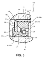
- FIG. 3 a first embodiment of the retaining device 27 is shown enlarged.
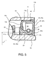
- the Fig. 5 shows a second embodiment of the retaining device 27th
- the retaining device 27 is supported radially on a rigid inner peripheral wall 29, which surrounds the tension spring 25 radially from the outside.
- the inner peripheral wall 29 is formed by an inner wall 29a of the support ring 19 and the inside of the shell wall 19a of the support ring 19.
- the retaining device 27 has in the first embodiment, an annular, in particular elastomeric insert part 27 a, which is inserted radially between the inner peripheral wall 29 and inner wall 29 a of the support ring 19 and the tension spring 25.
- the elastomeric insert part 27a fills a space 31 1 lying radially between the inner peripheral wall 29 or inner wall 29a of the support ring 19 and the tension spring 25 partly off.
- an annular gap R the gap width is less than the diameter of the tension spring 25, left.
- the retaining device 27 or the elastomeric insert part 27a has a contoured radial inner side 33, which is assigned to the tension spring 25 and adapted to the cross section of the tension spring 25.
- the radial shaft seal 13b has, in addition to the, a main lip forming sealing lip 17b an additional dust lip 35 i. Protective lip 35a on. Between the sealing lip 17b and dust lip 35 or protective lip 35a may be introduced grease, in particular rolling bearing grease for additional sealing.
- Grooves 39 and / or webs 41 are mounted on an outer circumferential surface 37 of the elastomeric insert part 27a, which can improve a sealing action between the elastomeric insert part 27a and the inner wall 29a of the support ring 19 or the inside of the shell wall 19a of the support ring 19.
- the in the Fig. 4 exemplary illustrated bearing assembly 1 has analogous to Fig. 1 an axle 3a and a shaft 3b, on the example of two inner rings 5a, 5b of a double-row roller bearing 7 sit.
- the double-row roller bearing 7, in the illustrated embodiment also has a common outer ring 9.
- Each inner ring 5a, 5b is provided with a seal raceway 11a, 11b.
- the inner ring 5a shown on the left is a first radial shaft sealing ring 13a used in a second embodiment.
- a second radial shaft seal 13b is also used in the second embodiment.
- the axle 3a is fixed, so that the seated on the axle 3a inner rings 5a, 5b are fixed.
- the outer ring 9 is rotatably mounted.
- the outer ring 9 forms insofar a rotatable hub, each with a static seal seat 15a, 15b for the two radial shaft seals 13a, 13b.
- the two radial shaft seals 13a, 13b rotate consequently with the outer ring 9 with.
- the sealing lips 17a, 17b slide on the respective associated sealing seats 15a, 15b.
- Fig. 5 illustrated second embodiment of a radial shaft seal 13a, 13b differs from the first embodiment according to Fig. 3 in that the elastomeric insert part 27a is replaced by a metal ring 27b.
- the retaining device 27 or the metal ring 27b is supported radially on a rigid inner peripheral wall 29, which surrounds the tension spring 25 radially from the outside.
- the inner peripheral wall 29 is formed by an inner wall 29a of the support ring 19 and the inside of the shell wall 19a of the support ring 19.
- the radial shaft seal 13b has, in addition to the, a main lip forming sealing lip 17b an additional dust lip 35 i. Protective lip 35a on. Between the sealing lip 17b and dust lip 35 or protective lip 35a may be introduced grease, in particular rolling bearing grease for additional sealing.
- the retaining device 27 of the second embodiment has the metal ring 27b inserted between the inner peripheral wall 29 and the tension spring 25.
- the metal ring 27b has an axially extending jacket wall 43 which is supported on the inner circumferential wall 29 and a radially extending annular end wall 45.
- the annular end wall 45 is arranged offset axially with respect to the tension spring 25.
- the annular end wall 45 has in the illustrated embodiment, a free end face 45a, which extends adjacent to the sealing ring 21 radially inwardly at least up to an inner diameter I of the tension spring 25.
Landscapes
- Engineering & Computer Science (AREA)
- General Engineering & Computer Science (AREA)
- Mechanical Engineering (AREA)
- Sealing Of Bearings (AREA)
- Sealing With Elastic Sealing Lips (AREA)
Abstract
Die Erfindung betrifft einen Radialwellendichtring (13a, 13b) aufweisend einen Stützring (19) und einen mit dem Stützring (19) verbundenen Dichtring (21), der eine radial nach innen weisende Dichtlippe (17a, 17b) aufweist, der eine Zugfeder (25) zugeordnet ist, die ausgebildet ist, in einer Betriebsposition des Radialwellendichtrings (13a, 13b) die Dichtlippe (17a, 17b) gegen eine mit der Dichtlippe (17a, 17b) zusammenwirkende Dichtungslaufbahn (11a, 11b) zu drücken, des Weiteren aufweisend eine zum Zurückhalten der Zugfeder (25) ausgebildete Rückhaltevorrichtung (27) und eine die Zugfeder (25) radial von außen umfangende starre Innenumfangswand (29), an der sich die Rückhaltevorrichtung (27) radial abstützt.
Description
- Die Erfindung betrifft einen Radialwellendichtring aufweisend einen Stützring und einen mit dem Stützring verbundenen Dichtring, der eine radial nach innen weisende Dichtlippe aufweist, der eine Zugfeder zugeordnet ist, die ausgebildet ist, in einer Betriebsposition des Radialwellendichtrings die Dichtlippe gegen eine mit der Dichtlippe zusammenwirkende Dichtungslaufbahn zu drücken.
- Die
DE 196 52 001 A1 beschreibt ein integriertes Dichtungssystem für automatische Getriebe, bestehend im wesentlichen aus einem einstückigen Teil, das gebildet wird aus einem ringförmigen Strukturelement aus Metall zur Montage in einen ringförmigen Raum zwischen einer Hauptabtriebswelle, einer Halbwelle und einem Gehäuse des automatischen Getriebes. Das integrierte Dichtungssystem weist einen Satz radialer Dichtungselemente aus Kautschuk auf, die ein erstes Element mit einer Dichtlippe aufweist, die gegen die Hauptabtriebswelle anliegt und welche eine Ringfeder zur Aufnahme von radialen Kräften aufnimmt, und die eine Schutzrippe aufweist, die ein Lösen der Feder verhindern soll. - Aufgabe der Erfindung ist es, einen Radialwellendichtring mit einer verbesserten Rückhaltevorrichtung zu schaffen.
- Die Aufgabe der Erfindung wird gelöst durch einen Radialwellendichtring aufweisend einen Stützring und einen mit dem Stützring verbundenen Dichtring, der eine radial nach innen weisende Dichtlippe aufweist, der eine Zugfeder zugeordnet ist, die ausgebildet ist, in einer Betriebsposition des Radialwellendichtrings die Dichtlippe gegen eine mit der Dichtlippe zusammenwirkende Dichtungslaufbahn zu drücken, des Weiteren aufweisend eine zum Zurückhalten der Zugfeder ausgebildete Rückhaltevorrichtung und eine die Zugfeder radial von außen umfangende starre Innenumfangswand, an der sich die Rückhaltevorrichtung radial abstützt.
- Die starre Umfangswand kann insbesondere eine aus metallischem Werkstoff bestehende Umfangswand sein. Die starre Umfangswand kann insoweit derart starr ausgebildet sein, dass sich die Gestalt, insbesondere der Innendurchmesser der Umfangswand unter Fliehkrafteinfluss, insbesondere aufgrund einer hohen Drehzahl der Umfangswand oder der Rückhaltevorrichtung nicht oder nur unwesentlich verändert. Eine unwesentliche Veränderung ist insbesondere dann gegeben, wenn eine Änderung des Durchmessers kleiner ist als der halbe Querschnitt der Zugfeder.
- Indem die Rückhaltevorrichtung sich an einer die Zugfeder radial von außen umfangenden starren Innenumfangswand abstützt, kann einer Formänderung, insbesondere einer Durchmesseraufweitung der Rückhaltevorrichtung aufgrund von Fliehkräften, die bei einer Rotation der Rückhaltevorrichtung, insbesondere bei hohen Drehzahlen auftreten können, entgegengewirkt werden. Dadurch bleibt die Rückhaltevorrichtung auch unter Fliehkrafteinfluss formstabil bzw. behält zumindest weitgehend oder sogar vollständig seine Ursprungsgestalt bei, so dass die Rückhaltevorrichtung ihre ursprüngliche Lage bezüglich der Zugfeder beibehält und folglich ein Rückhaltevermögen der Rückhaltevorrichtung verbessert ist bzw. insbesondere bei hohen Drehzahlen erst gewährleistet ist.
- Die Rückhaltevorrichtung kann ausgebildet sein, ein Herausfallen der Zugfeder aus der Anordnung des Radialwellendichtrings zu verhindern. Die Rückhaltevorrichtung kann insbesondere ausgebildet sein, ein Lösen der Zugfeder von ihrem Sitz an der Dichtlippe zu verhindern.
- Der Radialwellendichtring kann also einen Stützring aufweisen und einen mit dem Stützring verbundenen Dichtring, der eine radial nach innen weisende Dichtlippe aufweist, der eine Zugfeder zugeordnet ist, die ausgebildet ist, in einer Betriebsposition des Radialwellendichtrings die rotierende Dichtlippe gegen eine mit der Dichtlippe zusammenwirkende Dichtungslaufbahn zu drücken, des Weiteren aufweisend eine Rückhaltevorrichtung für die Zugfeder, bei dem die Rückhaltevorrichtung ausgebildet ist, ein fliehkraftbedingtes Aufweiten der mit der Dichtlippe mitrotierenden Zugfeder im Durchmesser auf ein vorgegebenes Höchstmaß zu begrenzen.
- Die Rückhaltevorrichtung kann sich in einer Betriebsposition des Radialwellendichtrings radial nach außen über die starre Innenumfangswand gegen einen statischen Dichtungssitz abstützen an dem der Radialwellendichtring eingesetzt ist.
- Die Rückhaltevorrichtung kann mit dem Stützring verbunden sein. Die Rückhaltevorrichtung kann insbesondere in radialer Richtung zwischen der Zugfeder und dem Stützring angeordnet sein. Die Rückhaltevorrichtung kann die Zugfeder von außen koaxial umgeben.
- In allen erfindungsgemäßen Ausführungen kann die starre Innenumfangswand durch eine Innenwand des Stützrings gebildet werden. Der Stützring kann dabei eine sich axial erstreckende Mantelwand aufweisen, die insbesondere eine Stützfläche für eine statische Dichtfläche des Radialwellendichtrings bildet, und eine sich radial erstreckende Ringwand aufweisen, an dessen nach innen weisendem Ende, welches einen Innendurchmesser des Stützringes bildet, der Dichtring befestigt ist.
- In allen erfindungsgemäßen Ausführungen kann die Rückhaltevorrichtung ein ringförmiges, insbesondere elastomeres Einsatzteil aufweisen, das radial zwischen der Innenumfangswand und der Zugfeder eingesetzt ist. Die Rückhaltevorrichtung kann insbesondere von einem zwischen Stützring und Zugfeder eingesetztem Elastomer-Ring gebildet werden.
- Das Einsatzteil und/oder der Elastomer-Ring kann einen radial zwischen Innenumfangswand und der Zugfeder liegenden Raum teilweise ausfüllen, unter Belassen lediglich eines Ringspaltes, dessen Spaltbreite geringer ist, als der Durchmesser der Zugfeder. Das Einsatzteil und/oder der Elastomer-Ring kann in die Innenumfangswand eingesetzt, eingepresst oder an die Innenumfangswand anvulkanisiert sein.
- Die Rückhaltevorrichtung, insbesondere das Einsatzteil und/oder der Elastomer-Ring kann eine auf die Zugfeder zuweisende, an den Querschnitt der Zugfeder angepasste konturierte radiale Innenseite aufweisen. Im Falle einer üblichen Zugfeder mit einem Kreisquerschnitt kann die der Zugfeder angepasst konturierte radiale Innenseite im Querschnitt eine Kreisbogenform aufweisen.
- Mit anderen Worten kann die Innenseite als Rille ausgebildet sein, welche die Zugfeder unter Belassen eines gleichmäßigen Spaltes über einen Teil ihrer Mantelfläche umgreift.
- In allen erfindungsgemäßen Ausführungen kann die Rückhaltevorrichtung somit eine an den Querschnitt der Zugfeder angepasst konturierte umlaufenden Rille aufweisen. Dabei kann die Rille ausgebildet sein, die Zugfeder unter Belassen eines Spaltes über einen Teil ihrer Mantelfläche zu umgreifen.
- In einer alternativen oder ergänzenden Ausführungsform zu einem Einsatzteil und/oder einem Elastomer-Ring kann die Rückhaltevorrichtung einen zwischen der Innenumfangswand und der Zugfeder eingesetzten Metall-Ring aufweisen. Der Metall-Ring kann insbesondere zwischen Stützring und Zugfeder angeordnet sein.
- Der die Rückhaltevorrichtung bildende Metall-Ring kann gegebenenfalls auch durch eine Ausformung des Stützrings gebildet werden.
- Der Metall-Ring kann eine sich an der Innenumfangswand abstützende axial erstreckende Mantelwand und eine sich radial erstreckende Ringstirnwand aufweisen. Dabei kann die Ringstirnwand bezüglich der Zugfeder axial versetzt angeordnet sein und einem freien Stirnende des Dichtrings benachbart sich radial nach innen mindestens bis zu einem Innendurchmesser der Zugfeder erstreckt.
- Die Erfindung betrifft außerdem eine Lageranordnung aufweisend eine Achse oder Welle mit einer Dichtungslaufbahn, eine drehbare Nabe oder einen Außenring des Wälzlagers, mit einem Dichtungssitz, sowie einen zwischen Nabe bzw. dem Außenring und Achse bzw. Welle angeordneten Radialwellendichtring wie erfindungsgemäß beschrieben.
- Bei der Lageranordnung kann die Achse oder Welle von einem Innenring eines Wälzlagers und/oder die Nabe von einem Außenring eines Wälzlagers gebildet werden. Alternativ kann bei der Lageranordnung die Achse oder Welle mit einem Innenring eines Wälzlagers und/oder die Nabe mit einem Außenring eines Wälzlagers verbunden sein.
- Die Lageranordnung kann einen Radialwellendichtring umfassen, der in einem axialen Abstand zur Dichtlippe eine Schutzlippe aufweist.
- Ein von Dichtlippe und Schutzlippe begrenzter Ringraum kann mit einem Wälzlagerfett befüllt sein.
- Zusammenfassend stellt die Erfindung somit eine Lösung bereit, bei der Wellendichtringe auch über den für sie zulässigen Drehzahlen verwendet werden können. Über die Zulässigkeit erhöhte Drehzahlen führen im Allgemeinen dazu, dass aufgrund der Fliehkraft die Dichtlippe von ihrer Dichtungsfläche abhebt. Unter demselben Fliehkrafteinfluss wird auch die Zugfeder d.h. die Schlauchfeder aufgeweitet. Bei weiterer Drehzahlsteigerung bzw. Fliehkrafterhöhung kann es sogar passieren, dass die Zugfeder abgeschleudert wird. ein Abheben kann bei gängigen zweilippigen Wellendichtringen beispielsweise bei ca. 8.000 Umdrehungen pro Minute auftreten. Dies ist nicht nur von der Fliehkraft, sondern auch von den Öldruckverhältnissen abhängig.
- Bei dem erfindungsgemäßen Radialwellendichtring ist deshalb zusätzlich eine Rückhaltevorrichtung eingebaut. Mit dieser Rückhaltevorrichtung kann der rotierende Radialwellendichtring über der allgemein üblichen Drehzahlgrenze von ca. 6.000 bis 8.000 Umdrehungen pro Minute verwendet werden, ohne dass es zu Undichtigkeiten kommt. Mit einem erfindungsgemäßen Radialwellendichtring können nun Drehzahlen von bis zu ca. 15.000 Umdrehungen pro Minute erreicht werden, ohne dass Undichtigkeiten auftreten.
- Der erfindungsgemäße Radialwellendichtring kann neben einer Hauptlippe eine zusätzliche Staublippe d.h. Schutzlippe aufweisen, wobei zwischen diesen beiden Dichtlippen Fett, insbesondere Wälzlagerfett zur zusätzlichen Abdichtung eingebracht sein kann.
- Zwei Ausführungsbeispiele der Erfindung sind exemplarisch in den beigefügten schematischen Zeichnungen dargestellt. Es zeigen:
- Fig. 1
- eine Ansicht im Halbschnitt einer beispielhaften Wälzlageranordnung mit einem Radialwellendichtring und einer erfindungsgemäßen ersten Ausführungsform einer Rückhaltevorrichtung mit einem ElastomerEinsatzteil,
- Fig. 2
- eine Ansicht im Halbschnitt des Radialwellendichtrings gemäß
Fig. 1 mit der ersten Ausführungsform der Rückhaltevorrichtung mit Elastomer-Einsatzteil, - Fig. 3
- eine vergrößerte Teilquerschnittsansicht des Radialwellendichtrings gemäß
Fig. 1 mit der ersten Ausführungsform der Rückhaltevorrichtung mit Elastomer-Einsatzteil, - Fig. 4
- eine Ansicht im Halbschnitt einer beispielhaften Wälzlageranordnung mit einem Radialwellendichtring und einer erfindungsgemäßen zweiten Ausführungsform einer Rückhaltevorrichtung mit einem Metall-Ring,
- Fig. 5
- eine vergrößerte Teilquerschnittsansicht des Radialwellendichtrings gemäß
Fig. 4 mit der zweiten Ausführungsform der Rückhaltevorrichtung mit Metall-Ring, - Die in der
Fig. 1 beispielhafte dargestellte Lageranordnung 1 weist eine Achse 3a bzw. eine Welle 3b auf, an der beispielhaft zwei Innenringe 5a, 5b eines zweireihigen Wälzlagers 7 aufsitzen. Das zweireihige Wälzlager 7 weist in der dargestellten Ausführung außerdem einen gemeinsamen Außenring 9 auf. Jeder Innenring 5a, 5b ist mit einer Dichtungslaufbahn 11a, 11b versehen. Zwischen dem Außenring 9 und dem inFig. 1 links dargestellten Innenring 5a ist ein erster Radialwellendichtring 13a in einer ersten Ausführungsform eingesetzt. Zwischen dem Außenring 9 und dem inFig. 1 rechts dargestellten Innenring 5b ist ein zweiter Radialwellendichtring 13b ebenfalls in der ersten Ausführungsform eingesetzt. In der dargestellten Ausführung ist die Achse 3a feststehend ausgebildet, so dass auch die auf der Achse 3a aufsitzenden Innenringe 5a, 5b feststehend sind. Demgemäß ist der Außenring 9 drehend gelagert. Der Außenring 9 bildet insoweit eine drehbare Nabe mit jeweils einem statischen Dichtungssitz 15a, 15b für die beiden Radialwellendichtringe 13a, 13b. Die beiden Radialwellendichtringe 13a, 13b drehen sich folglich mit dem Außenring 9 mit. Dabei gleiten die Dichtlippen 17a, 17b auf den jeweils zugeordneten Dichtungssitzen 15a, 15b. - In der
Fig. 2 ist einer der beiden Radialwellendichtringe 13a, 13b im Halbschnitt in Alleinstellung gezeigt. Der Radialwellendichtring 13b weist einen Stützring 19 und einen mit dem Stützring 19 verbundenen Dichtring 21 auf. - Der Stützring 19 weist eine sich axial erstreckende Mantelwand 19a auf, die insbesondere eine Stützfläche für den statischen Dichtungssitz 15b des Radialwellendichtrings bildet. Der Stützring 19 weist außerdem eine sich radial erstreckende Ringwand 19b auf, an dessen nach innen weisendem Ende 23, welches einen Innendurchmesser des Stützringes 19 bildet, der Dichtring 21 befestigt ist.
- Der Dichtring 21 trägt die radial nach innen weisende Dichtlippe 17b. Der Dichtlippe 17b ist eine Zugfeder 25 zugeordnet. Die Zugfeder 25 ist ausgebildet, in einer Betriebsposition des Radialwellendichtrings 13b die Dichtlippe 17b gegen die mit der Dichtlippe 17b zusammenwirkende Dichtungslaufbahn 11b zu drücken.
- Zum Zurückhalten der Zugfeder 25 weist der Radialwellendichtring 13b eine erfmdungsgemäße Rückhaltevorrichtung 27 auf.
- In der
Fig. 3 ist eine erste Ausführungsform der Rückhaltevorrichtung 27 vergrößert gezeigt. DieFig. 5 zeigt hingegen eine zweite Ausführungsform der Rückhaltevorrichtung 27. - Wie in der
Fig. 3 dargestellt stützt sich die Rückhaltevorrichtung 27 radial an einer starren Innenumfangswand 29 ab, welche die Zugfeder 25 radial von außen umfängt. Im dargestellten Ausführungsbeispiel wird die Innenumfangswand 29 durch eine Innenwand 29a des Stützrings 19 bzw. der Innenseite der Mantelwand 19a des Stützrings 19 gebildet. - Die Rückhaltevorrichtung 27 weist in der ersten Ausführungsform ein ringförmiges, insbesondere elastomeres Einsatzteil 27a auf, das radial zwischen der Innenumfangswand 29 bzw. Innenwand 29a des Stützrings 19 und der Zugfeder 25 eingesetzt ist.
- Das elastomere Einsatzteil 27a füllt dabei einen radial zwischen Innenumfangswand 29 bzw. Innenwand 29a des Stützrings 19 und der Zugfeder 25 liegenden Raum 31 1 teilweise aus. Dabei wird ein Ringspalt R, dessen Spaltbreite geringer ist als der Durchmesser der Zugfeder 25, belassen.
- Die Rückhaltevorrichtung 27 bzw. das elastomere Einsatzteil 27a weist eine auf die Zugfeder 25 zuweisende, an den Querschnitt der Zugfeder 25 angepasste konturierte radiale Innenseite 33 auf.
- Der Radialwellendichtring 13b weist neben der, eine Hauptlippe bildende Dichtlippe 17b eine zusätzliche Staublippe 35 d.h. Schutzlippe 35a auf. Zwischen Dichtlippe 17b und Staublippe 35 bzw. Schutzlippe 35a kann Fett, insbesondere Wälzlagerfett zur zusätzlichen Abdichtung eingebracht sein.
- An einer Außenumfangsfläche 37 des elastomeren Einsatzteils 27a sind in der gezeigten Ausführungsform Rillen 39 und/oder Stege 41 angebracht, welche eine Dichtwirkung zwischen dem elastomeren Einsatzteil 27a und der Innenwand 29a des Stützrings 19 bzw. der Innenseite der Mantelwand 19a des Stützrings 19 verbessern können.
- Die in der
Fig. 4 beispielhafte dargestellte Lageranordnung 1 weist analog zurFig. 1 eine Achse 3a bzw. eine Welle 3b auf, an der beispielhaft zwei Innenringe 5a, 5b eines zweireihigen Wälzlagers 7 aufsitzen. Das zweireihige Wälzlager 7 weist in der dargestellten Ausführung außerdem einen gemeinsamen Außenring 9 auf. Jeder Innenring 5a, 5b ist mit einer Dichtungslaufbahn 11a, 11b versehen. Zwischen dem Außenring 9 und dem inFig. 4 links dargestellten Innenring 5a ist ein erster Radialwellendichtring 13a in einer zweiten Ausführungsform eingesetzt. Zwischen dem Außenring 9 und dem inFig. 1 rechts dargestellten Innenring 5b ist ein zweiter Radialwellendichtring 13b ebenfalls in der zweiten Ausführungsform eingesetzt. In der dargestellten Ausführung ist die Achse 3a feststehend ausgebildet, so dass auch die auf der Achse 3a aufsitzenden Innenringe 5a, 5b feststehend sind. Demgemäß ist der Außenring 9 drehend gelagert. Der Außenring 9 bildet insoweit eine drehbare Nabe mit jeweils einem statischen Dichtungssitz 15a, 15b für die beiden Radialwellendichtringe 13a, 13b. Die beiden Radialwellendichtringe 13a, 13b drehen sich folglich mit dem Außenring 9 mit. Dabei gleiten die Dichtlippen 17a, 17b auf den jeweils zugeordneten Dichtungssitzen 15a, 15b. - Die in der
Fig. 5 dargestellte zweite Ausführungsform eines Radialwellendichtrings 13a, 13b unterscheidet sich von der ersten Ausführungsform gemäßFig. 3 dadurch, dass das elastomere Einsatzteil 27a durch einen Metall-Ring 27b ersetzt ist. - Die Rückhaltevorrichtung 27 bzw. der Metall-Ring 27b stützt sich radial an einer starren Innenumfangswand 29 ab, welche die Zugfeder 25 radial von außen umfängt. Im dargestellten Ausführungsbeispiel wird die Innenumfangswand 29 durch eine Innenwand 29a des Stützrings 19 bzw. der Innenseite der Mantelwand 19a des Stützrings 19 gebildet.
- Der Radialwellendichtring 13b weist neben der, eine Hauptlippe bildende Dichtlippe 17b eine zusätzliche Staublippe 35 d.h. Schutzlippe 35a auf. Zwischen Dichtlippe 17b und Staublippe 35 bzw. Schutzlippe 35a kann Fett, insbesondere Wälzlagerfett zur zusätzlichen Abdichtung eingebracht sein.
- Die Rückhaltevorrichtung 27 der zweiten Ausführungsform weist den zwischen der Innenumfangswand 29 und der Zugfeder 25 eingesetzten Metall-Ring 27b auf.
- Der Metall-Ring 27b weist eine sich an der Innenumfangswand 29 abstützende axial erstreckende Mantelwand 43 und eine sich radial erstreckende Ringstirnwand 45 auf.
- Die Ringstirnwand 45 ist bezüglich der Zugfeder 25 axial versetzt angeordnet. Die Ringstirnwand 45 weist im dargestellten Ausführungsbeispiel ein freies Stirnende 45a auf, das sich benachbart zum Dichtring 21 radial nach innen mindestens bis zu einem Innendurchmesser I der Zugfeder 25 erstreckt.
-
- 1
- Lageranordnung
- 3a
- Achse
- 3b
- Welle
- 5a, 5b
- Innenringe
- 7
- Wälzlager
- 9
- Außenring
- 11a, 11b
- Dichtungslaufbahnen
- 13a, 13b
- Radialwellendichtringe
- 15a, 15b
- Dichtungssitz
- 17a, 17b
- Dichtlippe
- 19
- Stützring
- 21
- Dichtring
- 23
- Ende
- 25
- Zugfeder
- 27
- Rückhaltevorrichtung
- 27a
- elastomeres Einsatzteil
- 27b
- Metall-Ring
- 29
- Innenumfangswand
- 29a
- Innenwand
- 31
- Raum
- 33
- Innenseite
- 35
- Staublippe
- 35a
- Schutzlippe
- 37
- Außenumfangsfläche
- 39
- Rillen
- 41
- Stege
- 43
- Mantelwand
- 45
- Ringstirnwand
- 45a
- Stirnende
- R
- Ringspalt
- I
- Innendurchmesser
Claims (10)
- Radialwellendichtring aufweisend einen Stützring (19) und einen mit dem Stützring (19) verbundenen Dichtring (21), der eine radial nach innen weisende Dichtlippe (17a, 17b) aufweist, der eine Zugfeder (25) zugeordnet ist, die ausgebildet ist, in einer Betriebsposition des Radialwellendichtrings (13a, 13b) die Dichtlippe (17a, 17b) gegen eine mit der Dichtlippe (17a, 17b) zusammenwirkende Dichtungslaufbahn (11a, 11b) zu drücken, des Weiteren aufweisend eine zum Zurückhalten der Zugfeder (25) ausgebildete Rückhaltevorrichtung (27) und eine die Zugfeder (25) radial von außen umfangende starre Innenumfangswand (29), an der sich die Rückhaltevorrichtung (27) radial abstützt.
- Radialwellendichtring nach Anspruch 1, bei dem die starre Innenumfangswand (29) durch eine Innenwand (29a) des Stützrings (19) gebildet wird.
- Radialwellendichtring nach Anspruch 1 oder 2, bei dem die Rückhaltevorrichtung (27) ein ringförmiges, insbesondere elastomeres Einsatzteil (27a) aufweist, das radial zwischen der Innenumfangswand (29) und der Zugfeder (25) eingesetzt ist.
- Radialwellendichtring nach Anspruch 1 oder 2, bei dem das Einsatzteil (27a) einen radial zwischen Innenumfangswand (29) und der Zugfeder (25) liegenden Raum (31) teilweise ausfüllt, unter Belassen lediglich eines Ringspaltes (R), dessen Spaltbreite geringer ist, als der Durchmesser der Zugfeder (25).
- Radialwellendichtring nach einem der Ansprüche 1 bis 4, bei dem die Rückhaltevorrichtung (27), insbesondere das Einsatzteil (27a) eine auf die Zugfeder (25) zuweisende, an den Querschnitt der Zugfeder (25) angepasst konturierte radiale Innenseite (33) aufweist.
- Radialwellendichtring nach Anspruch 5, bei dem die Innenseite (33) als Rille ausgebildet ist, welche die Zugfeder (25) unter Belassen eines gleichmäßigen Spaltes über einen Teil ihrer Mantelfläche umgreift.
- Radialwellendichtring nach einem der Ansprüche 1 bis 6, bei dem die Rückhaltevorrichtung (27) einen zwischen der Innenumfangswand (29) und der Zugfeder (25) eingesetzten Metall-Ring (27b) aufweist.
- Radialwellendichtring nach Anspruch 7, bei dem der Metall-Ring (27b) eine sich an der Innenumfangswand (29) abstützende axial erstreckende Mantelwand und eine sich radial erstreckende Ringstirnwand aufweist.
- Radialwellendichtring nach Anspruch 8, bei dem die Ringstirnwand bezüglich der Zugfeder axial versetzt angeordnet ist und einem freien Stirnende des Dichtrings benachbart sich radial nach innen mindestens bis zu einem Innendurchmesser der Zugfeder erstreckt.
- Lageranordnung aufweisend eine Achse (3a), eine Welle (3b) oder einen Innenring (5a, 5b) eines Wälzlagers (7), mit einer Dichtungslaufbahn (11a, 11b), eine drehbare Nabe oder ein Außenring (9) des Wälzlagers (7), mit einem Dichtungssitz (15a, 15b), sowie einen zwischen Nabe bzw. Außenring (9) des Wälzlagers (7) und Achse (3a) bzw. Welle (3b) oder Innenring (5a, 5b) angeordneten Radialwellendichtring (13a, 13b) nach einem der Ansprüche 1 bis 9.
Applications Claiming Priority (1)
| Application Number | Priority Date | Filing Date | Title |
|---|---|---|---|
| DE102010044177A DE102010044177A1 (de) | 2010-11-19 | 2010-11-19 | Radialwellendichtring mit einer Rückhaltevorrichtung für eine Zugfeder |
Publications (1)
| Publication Number | Publication Date |
|---|---|
| EP2455632A1 true EP2455632A1 (de) | 2012-05-23 |
Family
ID=45560633
Family Applications (1)
| Application Number | Title | Priority Date | Filing Date |
|---|---|---|---|
| EP11189683A Ceased EP2455632A1 (de) | 2010-11-19 | 2011-11-18 | Radialwellendichtring mit einer Rückhaltevorrichtung für eine Zugfeder |
Country Status (3)
| Country | Link |
|---|---|
| US (1) | US8668390B2 (de) |
| EP (1) | EP2455632A1 (de) |
| DE (1) | DE102010044177A1 (de) |
Cited By (2)
| Publication number | Priority date | Publication date | Assignee | Title |
|---|---|---|---|---|
| CN112780691A (zh) * | 2020-12-02 | 2021-05-11 | 陈新琴 | 一种平衡支撑轴承 |
| CN114992328A (zh) * | 2021-03-02 | 2022-09-02 | 卡科有限责任两合公司 | 轴密封件,特别是径向轴密封环 |
Families Citing this family (6)
| Publication number | Priority date | Publication date | Assignee | Title |
|---|---|---|---|---|
| DE102010054409A1 (de) * | 2010-12-14 | 2012-06-14 | Schaeffler Technologies Gmbh & Co. Kg | Dichteinrichtung und Drehlager mit dieser |
| ITTO20120845A1 (it) * | 2012-09-27 | 2014-03-28 | Skf Ab | Dispositivo di tenuta, in particolare per mozzi ruota di motociclette |
| JP2018035855A (ja) * | 2016-08-30 | 2018-03-08 | Nok株式会社 | 密封装置 |
| US11104489B2 (en) * | 2018-07-13 | 2021-08-31 | Aktiebolaget Skf | Annular seal having a garter spring for establishing a minimum interior diameter and seal plug including the seal |
| EP4435299B1 (de) * | 2023-03-20 | 2026-05-06 | Deere & Company | Fixiereinrichtung für einen wellendichtring und getriebeeinrichtung mit einer solchen |
| DE102023003412B4 (de) * | 2023-08-18 | 2025-03-13 | Mercedes-Benz Group AG | Wellenabdichtungsanordnung |
Citations (6)
| Publication number | Priority date | Publication date | Assignee | Title |
|---|---|---|---|---|
| US2208482A (en) * | 1936-08-19 | 1940-07-16 | Victor Mfg & Gasket Co | Grease retainer with integral diaphragm and outer seal |
| GB528214A (en) * | 1939-05-01 | 1940-10-24 | Angus George Co Ltd | Improvements in fluid-sealing devices for shafts, bearings and the like |
| US2565190A (en) * | 1946-09-28 | 1951-08-21 | Gen Tire & Rubber Co | Fluid seal |
| GB1449220A (en) * | 1972-12-11 | 1976-09-15 | Sperry Rand Corp | Seals control fo the composition of exhaust gases of internal |
| JPH07269713A (ja) * | 1994-03-31 | 1995-10-20 | Kiipaa Kk | 偏心動用耐圧オイルシール |
| DE19652001A1 (de) | 1995-12-13 | 1997-06-19 | Sabo Ind & Comercio Ltda | Verbesserung an einem integrierten Dichtungssystem für automatische Getriebe |
Family Cites Families (12)
| Publication number | Priority date | Publication date | Assignee | Title |
|---|---|---|---|---|
| US2362843A (en) * | 1938-12-22 | 1944-11-14 | Chicago Rawhide Mfg Co | Oil seal |
| US2334349A (en) * | 1941-10-29 | 1943-11-16 | Victor Mfg & Gasket Co | Oil seal construction |
| US3746351A (en) | 1971-07-19 | 1973-07-17 | Chicago Rawhide Mfg Co | Radial shaft seal with positively retained garter spring |
| US3871665A (en) * | 1973-04-09 | 1975-03-18 | Greene Tweed & Co Inc | Rod wiper assembly |
| US4015883A (en) * | 1973-10-23 | 1977-04-05 | Skf Industrial Trading And Development Company, B.V. | Annular sealing members and assemblies incorporating them |
| DE3205538C1 (de) | 1982-02-17 | 1983-07-21 | Fa. Carl Freudenberg, 6940 Weinheim | Dichtring |
| DE4114842C2 (de) * | 1991-05-07 | 1995-08-03 | Skf Gmbh | Mit einer Dichtungsanordnung versehenes Wälzlager |
| DE19600125A1 (de) | 1996-01-04 | 1997-07-10 | Fag Oem & Handel Ag | Dichtung mit fliehkraftentlasteter Dichtlippe |
| US6357757B1 (en) * | 2000-03-07 | 2002-03-19 | American Axle & Manufacturing, Inc. | Integral seal protector/labyrinth |
| US6712519B2 (en) * | 2000-07-28 | 2004-03-30 | Bombardier-Rotax Gmbh | Sealed bearing |
| US8016293B2 (en) * | 2006-01-03 | 2011-09-13 | Freudenberg-Nok General Partnership | Contaminant exclusion seal |
| TWM361579U (en) * | 2009-02-27 | 2009-07-21 | Chu Hung Oil Seals Ind Co Ltd | Hub oil seal |
-
2010
- 2010-11-19 DE DE102010044177A patent/DE102010044177A1/de active Pending
-
2011
- 2011-11-16 US US13/297,366 patent/US8668390B2/en active Active
- 2011-11-18 EP EP11189683A patent/EP2455632A1/de not_active Ceased
Patent Citations (6)
| Publication number | Priority date | Publication date | Assignee | Title |
|---|---|---|---|---|
| US2208482A (en) * | 1936-08-19 | 1940-07-16 | Victor Mfg & Gasket Co | Grease retainer with integral diaphragm and outer seal |
| GB528214A (en) * | 1939-05-01 | 1940-10-24 | Angus George Co Ltd | Improvements in fluid-sealing devices for shafts, bearings and the like |
| US2565190A (en) * | 1946-09-28 | 1951-08-21 | Gen Tire & Rubber Co | Fluid seal |
| GB1449220A (en) * | 1972-12-11 | 1976-09-15 | Sperry Rand Corp | Seals control fo the composition of exhaust gases of internal |
| JPH07269713A (ja) * | 1994-03-31 | 1995-10-20 | Kiipaa Kk | 偏心動用耐圧オイルシール |
| DE19652001A1 (de) | 1995-12-13 | 1997-06-19 | Sabo Ind & Comercio Ltda | Verbesserung an einem integrierten Dichtungssystem für automatische Getriebe |
Cited By (3)
| Publication number | Priority date | Publication date | Assignee | Title |
|---|---|---|---|---|
| CN112780691A (zh) * | 2020-12-02 | 2021-05-11 | 陈新琴 | 一种平衡支撑轴承 |
| CN112780691B (zh) * | 2020-12-02 | 2022-10-21 | 河北天马轴承制造有限公司 | 一种平衡支撑轴承 |
| CN114992328A (zh) * | 2021-03-02 | 2022-09-02 | 卡科有限责任两合公司 | 轴密封件,特别是径向轴密封环 |
Also Published As
| Publication number | Publication date |
|---|---|
| DE102010044177A1 (de) | 2012-05-24 |
| US8668390B2 (en) | 2014-03-11 |
| US20120134613A1 (en) | 2012-05-31 |
Similar Documents
| Publication | Publication Date | Title |
|---|---|---|
| DE102010044177A1 (de) | Radialwellendichtring mit einer Rückhaltevorrichtung für eine Zugfeder | |
| DE102009014923C5 (de) | Zweireihiges Kegelrollenlager, insbesondere zur Lagerung einer Rotorwelle einer Windkraftanlage | |
| DE102015118333A1 (de) | Dichtungsvorrichtung | |
| EP2948688B1 (de) | Zylinderrollenlager | |
| EP2729712B1 (de) | Pendelrollenlager mit dichtungsanordnung sowie flossenstabilisator mit dem pendelrollenlager | |
| DE112013002427T5 (de) | Abdichtstruktur | |
| WO2012019803A1 (de) | Dichtungsanordnung für wälzlager | |
| WO2011138107A1 (de) | Wälzlager mit integrierter abdichtung | |
| EP3810943B1 (de) | Wälzlager und dichtungsanordnung mit mindestens zwei dichtlippen | |
| DE102015212067B4 (de) | Wälzlagereinheit | |
| DE102016214350A1 (de) | Verfahren und Vorrichtung zur Herstellung eines Schrägrollenlagers | |
| DE4338261A1 (de) | Lager, insbesondere für Ausrücksysteme von Reibungskupplungen | |
| WO2007025975A2 (de) | Tandemschrägkugellager mit einer dictung an beiden stirnseiten | |
| DE102012216598B4 (de) | Radlageranordnung für ein Fahrzeug | |
| DE102015014833B3 (de) | Fanglagersystem | |
| DE102016209777A1 (de) | Wälzlager mit Einfüllöffnung für Wälzkörper | |
| DE102005019192B4 (de) | Dichtvorrichtung für ein Wälzlager | |
| DE102012224020A1 (de) | Lager | |
| DE102019200398A1 (de) | Selbst-ausrichtendes Rollenlager | |
| EP1058791A1 (de) | Nadellager | |
| DE102010014742A1 (de) | Faltenbalglager | |
| DE102015225164B4 (de) | Wälzlager, umfassend einen Dichtflansch | |
| DE112021003243T5 (de) | Dichtungsvorrichtung | |
| DE102007004716A1 (de) | Lageranordnung | |
| DE102021100401A1 (de) | Nabenlagereinheit mit einer Kombination aus Verschiebungsbegrenzer und Dichtung |
Legal Events
| Date | Code | Title | Description |
|---|---|---|---|
| PUAI | Public reference made under article 153(3) epc to a published international application that has entered the european phase |
Free format text: ORIGINAL CODE: 0009012 |
|
| AK | Designated contracting states |
Kind code of ref document: A1 Designated state(s): AL AT BE BG CH CY CZ DE DK EE ES FI FR GB GR HR HU IE IS IT LI LT LU LV MC MK MT NL NO PL PT RO RS SE SI SK SM TR |
|
| AX | Request for extension of the european patent |
Extension state: BA ME |
|
| 17P | Request for examination filed |
Effective date: 20121121 |
|
| 17Q | First examination report despatched |
Effective date: 20131014 |
|
| STAA | Information on the status of an ep patent application or granted ep patent |
Free format text: STATUS: THE APPLICATION HAS BEEN REFUSED |
|
| 18R | Application refused |
Effective date: 20141223 |