EP2453541B1 - Electric switching gear assembly - Google Patents
Electric switching gear assembly Download PDFInfo
- Publication number
- EP2453541B1 EP2453541B1 EP11175928.8A EP11175928A EP2453541B1 EP 2453541 B1 EP2453541 B1 EP 2453541B1 EP 11175928 A EP11175928 A EP 11175928A EP 2453541 B1 EP2453541 B1 EP 2453541B1
- Authority
- EP
- European Patent Office
- Prior art keywords
- electric switchgear
- fact
- accordance
- arrangement
- switchgear
- Prior art date
- Legal status (The legal status is an assumption and is not a legal conclusion. Google has not performed a legal analysis and makes no representation as to the accuracy of the status listed.)
- Active
Links
- 238000009434 installation Methods 0.000 claims description 10
- 230000008878 coupling Effects 0.000 claims description 6
- 238000010168 coupling process Methods 0.000 claims description 6
- 238000005859 coupling reaction Methods 0.000 claims description 6
- 230000001681 protective effect Effects 0.000 claims description 4
- XLYOFNOQVPJJNP-UHFFFAOYSA-N water Substances O XLYOFNOQVPJJNP-UHFFFAOYSA-N 0.000 claims description 2
- 230000000712 assembly Effects 0.000 description 2
- 238000000429 assembly Methods 0.000 description 2
- 230000001419 dependent effect Effects 0.000 description 1
- 230000000694 effects Effects 0.000 description 1
- 230000007613 environmental effect Effects 0.000 description 1
- 230000013011 mating Effects 0.000 description 1
Images


Classifications
-
- H—ELECTRICITY
- H02—GENERATION; CONVERSION OR DISTRIBUTION OF ELECTRIC POWER
- H02G—INSTALLATION OF ELECTRIC CABLES OR LINES, OR OF COMBINED OPTICAL AND ELECTRIC CABLES OR LINES
- H02G3/00—Installations of electric cables or lines or protective tubing therefor in or on buildings, equivalent structures or vehicles
- H02G3/02—Details
- H02G3/08—Distribution boxes; Connection or junction boxes
- H02G3/14—Fastening of cover or lid to box
-
- H—ELECTRICITY
- H02—GENERATION; CONVERSION OR DISTRIBUTION OF ELECTRIC POWER
- H02G—INSTALLATION OF ELECTRIC CABLES OR LINES, OR OF COMBINED OPTICAL AND ELECTRIC CABLES OR LINES
- H02G3/00—Installations of electric cables or lines or protective tubing therefor in or on buildings, equivalent structures or vehicles
- H02G3/02—Details
- H02G3/08—Distribution boxes; Connection or junction boxes
- H02G3/10—Distribution boxes; Connection or junction boxes for surface mounting on a wall
-
- H—ELECTRICITY
- H02—GENERATION; CONVERSION OR DISTRIBUTION OF ELECTRIC POWER
- H02G—INSTALLATION OF ELECTRIC CABLES OR LINES, OR OF COMBINED OPTICAL AND ELECTRIC CABLES OR LINES
- H02G3/00—Installations of electric cables or lines or protective tubing therefor in or on buildings, equivalent structures or vehicles
- H02G3/02—Details
- H02G3/08—Distribution boxes; Connection or junction boxes
- H02G3/12—Distribution boxes; Connection or junction boxes for flush mounting
Definitions
- the present invention is based on a conceived according to the preamble of the main claim electrical switching device arrangement.
- Such electrical switching device arrangements are generally intended to effect the switching on and off of a circuit or the switching from one to another circuit.
- a variety of contact systems can be used.
- the operation of such electrical switching device arrangements may, for. B. by pivoting designed as a rocker actuator from an initial position into one or more functional positions, wherein the functional positions can be performed detent and / or groping.
- a push-button switch can be used, in which case the actuating element is brought by push buttons from its rest position to its switching position.
- such electrical switchgear assemblies are equipped with a light source so that either a function display and / or a search lighting can be realized or can.
- the switching device arrangement is provided with a particularly large-area running actuator, d. H. This covers at least two bays of the coming to use electrical switching devices.
- an electrical / electronic installation device in particular a door communication device has become known.
- This has a housing, the base part is provided for receiving at least one functional unit and the cover part at least for arranging and receiving a plurality of operation keys.
- at least a first housing chamber for receiving a loudspeaker unit is provided, wherein between the sound exit area the speaker unit and the cover part at least a first seal is arranged.
- the design module of such an electrical / electronic installation device covers two bays.
- the present invention is therefore based on the object to provide an electrical switching device arrangement, the design assembly is so stunned, so that design frame can be used with any number of recording options for on-demand installation of other electrical equipment use.
- This object is achieved by the features stated in the characterizing part of the main claim.
- the arrangement of the devices to be installed can be selected as desired or as required in the case of a design frame offering at least three receiving possibilities. It is also particularly advantageous that the design framework of different design lines already in the usual sales program can be used without any changes.
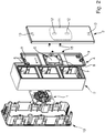
- such an electrical switching device arrangement consists essentially of an electrical switching device 1 and at least three bays of such electrical switching devices 1 overlapping design assembly, wherein the electrical switching device 1 is provided with an actuating element 2, which has three bays such electrical Covered switching devices 1, and wherein the design assembly consists of a design frame 3 and a releasably inserted into the design frame 3 function panel 4.
- the function panel 4 also covers three slots of such electrical switching devices.
- the functional plate 4 has an opening 6 enabling the coupling between the electrical switching device 1 and the associated actuating element 2.
- the opening 6 is surrounded by an integrally formed on the front of the function panel 4 protective collar 7.
- a circumferential Wasserabtropfkante 8 is also formed on the back of the outer region of the function plate 4.
- two bearing elements 9 are formed on the front side of the functional plate 4, in which holding two correspondingly executed arranged on the back of the actuating element 2 bearing counter-elements 10 engage.
- a cooperating with the protective collar 7 of the function plate 4 counter contour 11 is present at the back of the actuating element.
- two coupling elements 12 are also provided, which are integrally formed on the back of the actuating element 2.
- the switching device 1 is executed in each case as a rocker switch in the illustrated embodiments.
- the switching device 1 and the design frame 3 is carried out for performing a flush-mounted installation.
- the design module covers three bays of such electrical switching device 1.
- the designed as a rocker actuator 2 also covers three bays such electrical switching devices 1 and also the function plate 4 is provided to cover three bays.
- the switchgear assembly is designed to cover an order of magnitude that is normally covered by three normal size switchgears 1.
- the switching device 1 and the design frame 3 is carried out to perform a surface-mounted installation.
- the design frame 3 is additionally assigned a surface-mounted housing part 13.
- the design module covers three bays of such electrical switching device 1.
- the designed as a rocker actuator 2 also covers three bays such electrical switching devices 1 and also the function plate 4 is provided to cover three bays.
- the switchgear assembly is designed to cover an order of magnitude that is normally covered by three normal size switchgears 1.
- the switching device 1 and the design frame 3 is carried out for performing a flush-mounted installation.
- the design module covers four bays of such electrical switching device 1.
- the designed as a rocker actuator 2 covers only three bays such electrical switching devices 1, and also the function panel 4 is provided to cover three bays.
- another electrical device 14 in the immediate vicinity of the switching device arrangement.
- the arrangement of the electrical devices 1, 14 to be installed can thus be selected as desired or as required.
- the further electrical device 14 is designed as a loudspeaker assembly and occupies the lower slot.
- such a further electrical device 14 could also be designed as a ground contact socket, motion detector, orientation light, etc., and occupy the upper slot. It is also possible to use a design module whose design frame 3 five, six or more slots for such electrical switching devices 1 and other electrical equipment 14 is available. If necessary, therefore, the installation of several other electrical devices 14 in a simple manner shapely realized. It is particularly advantageous in such an embodiment that the arrangement of the electrical switching device 1 and the other electrical devices 14 with respect to their bays arbitrary or can be selected as needed. It is also advantageous that the already located in the usual sales program Design frames of different design lines without having to make changes. Without causing any additional costs, such an electrical switching device arrangement can thus be optically integrated into all design lines.
- the clip hooks 5 integrally formed on the rear side of the functional panel 4 are made comparatively small, so that the functional panel 4 can be inserted into the design frame 3 in a particularly simple manner due to its elastic deformability, or can be released therefrom again. At the same time, these clip hooks 5 also ensure a secure fastening of the functional plate 4 in the design frame 3.
- two bearing elements 10 are formed on the back of the actuating element for exact storage of the actuating element 2.
- a mating contour 11 is integrally formed on the rear side of the actuating element 2, which cooperates with the protective collar 7 of the functional plate 4.
- two pin-shaped coupling elements 12 are integrally formed on the back of the actuating element 2, which produce the mechanical coupling with the contact piece of the electrical switching device 1.
Description
Die vorliegende Erfindung geht von einer gemäß Oberbegriff des Hauptanspruches konzipierten elektrischen Schaltgeräteanordnung aus.The present invention is based on a conceived according to the preamble of the main claim electrical switching device arrangement.
Derartige elektrische Schaltgeräteanordnungen sind in der Regel dafür vorgesehen, die Ein- und Ausschaltung eines Stromkreises bzw. die Umschaltung von einem auf einen anderen Stromkreis zu bewirken. Bei solchen elektrischen Schaltgeräteanordnungen können die unterschiedlichsten Kontaktsysteme Anwendung finden. Die Betätigung solcher elektrischen Schaltgeräteanordnungen kann z. B. durch ein Verschwenken eines als Betätigungswippe ausgebildeten Betätigungselementes von einer Ausgangsposition in eine oder mehrere Funktionsstellungen erfolgen, wobei die Funktionsstellungen rastend und/oder tastend ausgeführt sein können. Selbstverständlich kann bei einer derartigen elektrischen Schaltgeräteanordnung jedoch auch ein Tastschalter zur Anwendung kommen, wobei dann das Betätigungselement durch Drucktasten ausgehend von seiner Ruheposition in seine Schaltposition gebracht wird. Oftmals sind solche elektrischen Schaltgeräteanordnungen mit einem Leuchtmittel ausgerüstet, damit entweder eine Funktionsanzeige und/oder eine Suchbeleuchtung realisiert werden kann bzw. können. Im vorliegenden Fall ist die Schaltgeräteanordnung mit einem besonders großflächig ausgeführten Betätigungselement versehen, d. h. dieses überdeckt zumindest zwei Einbauplätze der zum Einsatz kommenden elektrischen Schaltgeräte.Such electrical switching device arrangements are generally intended to effect the switching on and off of a circuit or the switching from one to another circuit. In such electrical switching device arrangements, a variety of contact systems can be used. The operation of such electrical switching device arrangements may, for. B. by pivoting designed as a rocker actuator from an initial position into one or more functional positions, wherein the functional positions can be performed detent and / or groping. Of course, in such an electrical switching device arrangement, however, a push-button switch can be used, in which case the actuating element is brought by push buttons from its rest position to its switching position. Often, such electrical switchgear assemblies are equipped with a light source so that either a function display and / or a search lighting can be realized or can. In the present case, the switching device arrangement is provided with a particularly large-area running actuator, d. H. This covers at least two bays of the coming to use electrical switching devices.
Eine dem Oberbegriff des Hauptanspruches entsprechende elektrische Schaltgeräteanordnung ist durch den Katalog der Firma Jung aus dem Jahre 2010, Seiten 388 und 389 bekannt geworden. Diese elektrische Schaltgeräteanordnung bestehend aus einem elektrischen Schaltgerät und einer drei Einbauplätze solcher elektrischen Schaltgeräte überdeckenden Designbaugruppe, wobei das elektrische Schaltgerät mit einem Betätigungselement versehen ist, welches ebenfalls drei Einbauplätze solcher Schaltgeräte überdeckt. Das elektrische Schaltgerät ist als Wippenschalter ausgebildet und die Designbaugruppe besteht aus einer Funktionsplatte, welche untrennbar mit einem Designrahmen umgeben ist. Oftmals besteht jedoch der Bedarf, eine solche Schaltgeräteanordnung zusätzlich mit weiteren elektrischen Geräten wie Schutzkontaktsteckdosen, Bewegungsmeldern, Orientierungslichtern, usw. zu versehen. Bei einer solchen Ausführung müssen solche weiteren elektrischen Geräte jedoch mittels eines separaten Designrahmens in Zuordnung zu der bekannten Schaltgeräteanordnung installiert werden, was nicht nur unschön aussieht, sondern auch vergleichsweise teuer und aufwändig ist.An according to the preamble of the main claim electrical switchgear assembly has become known through the catalog of the company Jung from the year 2010, pages 388 and 389. This electrical switching device arrangement consisting of an electrical switching device and a three slots of such electrical switching devices covering design assembly, wherein the electrical switching device is provided with an actuating element, which is also three Slots of such switching devices covered. The electrical switching device is designed as a rocker switch and the design assembly consists of a functional plate which is inseparably surrounded by a design frame. Often, however, there is a need to provide such a switchgear assembly additionally with other electrical equipment such as sockets, motion detectors, orientation lights, etc. In such an embodiment, however, such further electrical devices must be installed by means of a separate design frame in association with the known switching device arrangement, which not only looks ugly, but is also relatively expensive and expensive.
Zudem ist durch die
Außerdem sind durch die
Der vorliegenden Erfindung liegt deshalb die Aufgabe zugrunde eine elektrische Schaltgeräteanordnung zu schaffen, dessen Designbaugruppe derart ausgerührt ist, so dass Designrahmen mit beliebig vielen Aufnahmemöglichkeiten zur bedarfsweisen Installation weiterer elektrischer Geräte Verwendung finden können. Diese Aufgabe wird durch die im kennzeichnenden Teil des Hauptanspruches angegebenen Merkmale gelöst. Bei einer solchermaßen ausgebildeten elektrischen Schaltgeräteanordnung ist besonders vorteilhaft, dass die Anordnung der zu installierenden Geräte bei einem zumindest drei Aufnahmemöglichkeiten bietenden Designrahmen beliebig bzw. je nach Bedarf gewählt werden kann. Weiter ist besonders vorteilhaft, dass die sich schon im üblichen Verkaufsprogramm befindlichen Designrahmen unterschiedlicher Designlinien ohne Änderungen vornehmen zu müssen Verwendung finden können.The present invention is therefore based on the object to provide an electrical switching device arrangement, the design assembly is so stunned, so that design frame can be used with any number of recording options for on-demand installation of other electrical equipment use. This object is achieved by the features stated in the characterizing part of the main claim. In an electrical switching device arrangement formed in this way, it is particularly advantageous that the arrangement of the devices to be installed can be selected as desired or as required in the case of a design frame offering at least three receiving possibilities. It is also particularly advantageous that the design framework of different design lines already in the usual sales program can be used without any changes.
Weitere vorteilhafte Ausgestaltungen des erfindungsgemäßen Gegenstandes sind in den Unteransprüchen angegeben und werden anhand dreier in den Zeichnungen dargestellter Ausführungsbeispiele näher erläutert. Dabei zeigen:
- Fig. 1:
- prinziphaft ein erstes Ausführungsbeispiel einer solchen elektrischen Schaltgeräteanordung räumlich in Explosionsdarstellung;
- Fig. 2:
- prinziphaft ein zweites Ausführungsbeispiel einer solchen elektrischen Schaltgeräteanordung räumlich in Explosionsdarstellung;
- Fig. 3:
- prinziphaft ein drittes Ausführungsbeispiel einer solchen elektrischen Schaltgeräteanordung, sowie ein zugeorndetes weiteres elektrisches Gerät, räumlich in Explosionsdarstellung;
- Fig. 4:
- prinziphaft die Rückseite der Funktionsplatte in räumlicher Darstellung;
- Fig. 5:
- prinziphaft die Rückseite des Betätigungselementes in räumlicher Darstellung.
- Fig. 1:
- in principle, a first embodiment of such electrical Schaltgeräteanordung spatially in an exploded view;
- Fig. 2:
- in principle, a second embodiment of such electrical Schaltgeräteanordung spatially in exploded view;
- 3:
- in principle, a third embodiment of such electrical Schaltgeräteanordung, and a zugeorndetes further electrical device, spatially in exploded view;
- 4:
- in principle, the back of the functional plate in a spatial representation;
- Fig. 5:
- in principle, the back of the actuator in a spatial representation.
Wie aus den Figuren hervorgeht, besteht eine solche elektrische Schaltgeräteanordnung im wesentlichen aus einem elektrischen Schaltgerät 1 und einer zumindest drei Einbauplätze solcher elektrischen Schaltgeräte 1 überdeckenden Designbaugruppe, wobei das elektrische Schaltgerät 1 mit einem Betätigungselement 2 versehen ist, welches drei Einbauplätze solcher elektrischen Schaltgeräte 1 überdeckt, und wobei die Designbaugruppe aus einem Designrahmen 3 und aus einer wieder lösbar in den Designrahmen 3 einsetzbaren Funktionsplatte 4 besteht. Die Funktionsplatte 4 überdeckt ebenfalls drei Einbauplätze solcher elektrischen Schaltgeräte 1.As can be seen from the figures, such an electrical switching device arrangement consists essentially of an
Wie des Weiteren aus den Figuren hervorgeht, sind an die Funktionsplatte 4 vier mit dem Designrahmen 3 zusammenwirkende Clipshaken 5 angeformt. Zwei Clipshaken 5 sind dabei jeweils an den beiden Schmalseiten der Funktionsplatte 4 vorhanden. Zudem weist die Funktionsplatte 4 eine die Kopplung zwischen dem elektrischen Schaltgerät 1 und dem zugehörigen Betätigungselement 2 ermöglichende Öffnung 6 auf. Zur Realisierung eines effektiven Spritzwasserschutzes ist die Öffnung 6 von einem einstückig an die Vorderseite der Funktionsplatte 4 angeformten Schutzkragen 7 umgeben. Zum gleichen Zweck ist zudem rückseitig an den Außenbereich der Funktionsplatte 4 eine umlaufende Wasserabtropfkante 8 angeformt. Zur funktionsgerechten Lagerung des Betätigungselementes 2 sind an die Vorderseite der Funktionsplatte 4 zwei Lagerelemente 9 angeformt, in welche haltend zwei entsprechend ausgeführte an der Rückseite des Betätigungselementes 2 angeordnete Lagergegenelemente 10 eingreifen. Außerdem ist an der Rückseite des Betätigungselements 2 eine mit dem Schutzkragen 7 der Funktionsplatte 4 zusammenwirkende Gegenkontur 11 vorhanden. Zur Kopplung mit dem Schaltgerät 1 sind zudem zwei Koppelelemente 12 vorgesehen, die an die Rückseite des Betätigungselementes 2 angeformt sind. Das Schaltgerät 1 ist bei den dargestellten Ausführungsbeispielen jeweils als Wippenschalter ausgeführt.As can further be seen from the figures, four
Wie insbesondere aus
Wie insbesondere aus
Wie insbesondere aus
Wie insbesondere aus
Wie insbesondere aus
Wie des weiteren aus den
Claims (12)
- Electric switchgear arrangement, consisting of an electric switchgear (1) and a design module covering at least two mounting spaces of such electric switchgear, wherein the electric switchgear is provided with an actuating element (2) covering at least two mounting spaces of such electric switchgear, characterized by the fact that the design module consists of a design frame (3) and of a function plate (4) to be inserted detachably into the design frame (3).
- Electric switchgear arrangement in accordance with Claim 1, characterized by the fact that at least one clip (5) interacting with the design frame (3) is moulded to the function plate (4).
- Electric switchgear arrangement in accordance with Claims 1 or 2, characterized by the fact that the function plate (4) provides at least one opening (6) allowing coupling of the electric switchgear (1) with the pertaining actuating element (2).
- Electric switchgear arrangement in accordance with Claim 3, characterized by the fact that the at least one opening (6) of the function plate (4) is surrounded by a protective collar (7) moulded to the function plate (4) in one piece.
- Electric switchgear arrangement in accordance with any of Claims 1 to 4, characterized by the fact that a surrounding water drip edge (8) is moulded to the outer edge of the function plate (4).
- Electric switchgear arrangement in accordance with any of Claims 1 to 5, characterized by the fact that at least one bearing element (9) interacting with the actuating element (2) is moulded to the function plate (4).
- Electric switchgear arrangement in accordance with any of Claims 1 to 6, characterized by the fact that the electric switchgear (1) is designed as rocker switch.
- Electric switchgear arrangement in accordance with any of Claims 1 to 6, characterized by the fact that the electric switchgear (1) is designed as push button.
- Electric switchgear arrangement in accordance with any of Claims 1 to 8, characterized by the fact that the design frame (3) is designed for use of the switchgear (1) in a flush-mounted installation.
- Electric switchgear arrangement in accordance with any of Claims 1 to 8, characterized by the fact that the design frame (3) is designed for use of the switchgear (1) in a surface-mounted installation.
- Electric switchgear arrangement in accordance with any of Claims 1 to 10, characterized by the fact that the actuating element (2) covers three mounting spaces for such switchgear (1).
- Electric switchgear arrangement in accordance with any of Claims 1 to 11, characterized by the fact that the design module covers at least three mounting spaces for such switchgear (1).
Applications Claiming Priority (1)
| Application Number | Priority Date | Filing Date | Title |
|---|---|---|---|
| DE102010060572.7A DE102010060572B4 (en) | 2010-11-16 | 2010-11-16 | Electrical switching device arrangement |
Publications (3)
| Publication Number | Publication Date |
|---|---|
| EP2453541A2 EP2453541A2 (en) | 2012-05-16 |
| EP2453541A3 EP2453541A3 (en) | 2014-12-10 |
| EP2453541B1 true EP2453541B1 (en) | 2017-01-25 |
Family
ID=45375145
Family Applications (1)
| Application Number | Title | Priority Date | Filing Date |
|---|---|---|---|
| EP11175928.8A Active EP2453541B1 (en) | 2010-11-16 | 2011-07-29 | Electric switching gear assembly |
Country Status (4)
| Country | Link |
|---|---|
| EP (1) | EP2453541B1 (en) |
| DE (1) | DE102010060572B4 (en) |
| ES (1) | ES2623022T3 (en) |
| PT (1) | PT2453541T (en) |
Families Citing this family (2)
| Publication number | Priority date | Publication date | Assignee | Title |
|---|---|---|---|---|
| BE1022000B1 (en) * | 2014-06-30 | 2016-02-03 | Niko Nv | COVER FOR ELECTRICAL INSTALLATION MATERIAL |
| DE102014119271A1 (en) * | 2014-12-19 | 2016-06-23 | Schneider Electric Industries Sas | Electrical installation device |
Family Cites Families (5)
| Publication number | Priority date | Publication date | Assignee | Title |
|---|---|---|---|---|
| DE7730438U1 (en) * | 1977-10-01 | 1979-03-15 | Brown, Boveri & Cie Ag, 6800 Mannheim | Electrical installation device |
| US5189259A (en) * | 1990-05-17 | 1993-02-23 | Lightolier, Inc. | Face plate having press-fit attachment to electrical switches, outlets and the like |
| DE10209657A1 (en) * | 2002-03-05 | 2003-09-18 | Abb Patent Gmbh | Bus Technology Installation System |
| US20060072302A1 (en) * | 2004-10-01 | 2006-04-06 | Chien Tseng L | Electro-luminescent (EL) illuminated wall plate device with push-tighten frame means |
| DE102007045870B4 (en) * | 2007-09-25 | 2012-01-05 | Albrecht Jung Gmbh & Co. Kg | Electrical / electronic installation device |
-
2010
- 2010-11-16 DE DE102010060572.7A patent/DE102010060572B4/en not_active Expired - Fee Related
-
2011
- 2011-07-29 PT PT111759288T patent/PT2453541T/en unknown
- 2011-07-29 ES ES11175928.8T patent/ES2623022T3/en active Active
- 2011-07-29 EP EP11175928.8A patent/EP2453541B1/en active Active
Also Published As
| Publication number | Publication date |
|---|---|
| ES2623022T3 (en) | 2017-07-10 |
| EP2453541A3 (en) | 2014-12-10 |
| DE102010060572B4 (en) | 2015-05-21 |
| PT2453541T (en) | 2017-05-25 |
| DE102010060572A1 (en) | 2012-05-16 |
| EP2453541A2 (en) | 2012-05-16 |
Similar Documents
| Publication | Publication Date | Title |
|---|---|---|
| DE102008060347A1 (en) | Electrical/electronic installation device e.g. switch, for connection to e.g. installation network bus system of building automation system, has contact element that is component of auxiliary module which is coupled to plastic housing | |
| EP2453541B1 (en) | Electric switching gear assembly | |
| DE102013104259B3 (en) | Electrical/electronic installation apparatus for installation of wiring boxes in building system, has conditioning plates associated with spring that is fastened on support and supported under spring action against inner wall of box | |
| EP3527886B1 (en) | Arrangment comprising an electrical/ electronic installation device and an electric lighting device | |
| CH695715A5 (en) | Electrical house installation apparatus e.g. power socket, has support ring between functional insert and fastening plate, where ring is fastened to fastening plate, and functional insert is fastened to fastening plate by support ring | |
| EP1797261B1 (en) | Device for actuating a lock in a vehicle | |
| DE102004024093B4 (en) | cover | |
| EP2930809B1 (en) | Electric/electronic installation device | |
| DE102017006870A1 (en) | Electrical installation device | |
| DE102005062489A1 (en) | Electrical / electronic installation device | |
| DE102013205884A1 (en) | Modular system of a control unit | |
| EP1648066A1 (en) | Surface mounting device | |
| EP2438836B1 (en) | Assembly of at least one lightweight construction board with a carrier plate comprising a power supply and lightweight furniture | |
| EP2811599B1 (en) | Electric/electronic installation device | |
| DE102014110652B3 (en) | Electrical / electronic installation device | |
| EP1753106A1 (en) | Fastening element | |
| DE102013105893B3 (en) | Electrical / electronic installation device | |
| DE19717909C2 (en) | Electric device | |
| EP2017692B1 (en) | Computer enclosure | |
| DE102008017637B4 (en) | Home station for a door intercom | |
| DE102022121671B3 (en) | Bracket for tool-free mounting of wireless switches on electrical connection units with cover frames | |
| DE102007045871A1 (en) | Electrical / electronic installation device | |
| DE102013110461A1 (en) | Electrical / electronic installation device | |
| DE102013103660B3 (en) | Module apparatus e.g. rack server inserted into rack of arrangement, has operating and/or display panel which is dimensioned to partly cover attachment element in insertion direction of module apparatus into rack | |
| DE10249123B4 (en) | Electrotechnical device for use in installation boxes |
Legal Events
| Date | Code | Title | Description |
|---|---|---|---|
| PUAI | Public reference made under article 153(3) epc to a published international application that has entered the european phase |
Free format text: ORIGINAL CODE: 0009012 |
|
| AK | Designated contracting states |
Kind code of ref document: A2 Designated state(s): AL AT BE BG CH CY CZ DE DK EE ES FI FR GB GR HR HU IE IS IT LI LT LU LV MC MK MT NL NO PL PT RO RS SE SI SK SM TR |
|
| AX | Request for extension of the european patent |
Extension state: BA ME |
|
| PUAL | Search report despatched |
Free format text: ORIGINAL CODE: 0009013 |
|
| AK | Designated contracting states |
Kind code of ref document: A3 Designated state(s): AL AT BE BG CH CY CZ DE DK EE ES FI FR GB GR HR HU IE IS IT LI LT LU LV MC MK MT NL NO PL PT RO RS SE SI SK SM TR |
|
| AX | Request for extension of the european patent |
Extension state: BA ME |
|
| RIC1 | Information provided on ipc code assigned before grant |
Ipc: H02G 3/10 20060101ALI20141106BHEP Ipc: H02G 3/14 20060101AFI20141106BHEP Ipc: H02G 3/12 20060101ALI20141106BHEP |
|
| 17P | Request for examination filed |
Effective date: 20141222 |
|
| RBV | Designated contracting states (corrected) |
Designated state(s): AL AT BE BG CH CY CZ DE DK EE ES FI FR GB GR HR HU IE IS IT LI LT LU LV MC MK MT NL NO PL PT RO RS SE SI SK SM TR |
|
| GRAP | Despatch of communication of intention to grant a patent |
Free format text: ORIGINAL CODE: EPIDOSNIGR1 |
|
| GRAS | Grant fee paid |
Free format text: ORIGINAL CODE: EPIDOSNIGR3 |
|
| GRAA | (expected) grant |
Free format text: ORIGINAL CODE: 0009210 |
|
| INTG | Intention to grant announced |
Effective date: 20161201 |
|
| AK | Designated contracting states |
Kind code of ref document: B1 Designated state(s): AL AT BE BG CH CY CZ DE DK EE ES FI FR GB GR HR HU IE IS IT LI LT LU LV MC MK MT NL NO PL PT RO RS SE SI SK SM TR |
|
| REG | Reference to a national code |
Ref country code: GB Ref legal event code: FG4D Free format text: NOT ENGLISH |
|
| REG | Reference to a national code |
Ref country code: CH Ref legal event code: EP |
|
| REG | Reference to a national code |
Ref country code: AT Ref legal event code: REF Ref document number: 864613 Country of ref document: AT Kind code of ref document: T Effective date: 20170215 |
|
| REG | Reference to a national code |
Ref country code: IE Ref legal event code: FG4D Free format text: LANGUAGE OF EP DOCUMENT: GERMAN |
|
| REG | Reference to a national code |
Ref country code: DE Ref legal event code: R096 Ref document number: 502011011581 Country of ref document: DE |
|
| REG | Reference to a national code |
Ref country code: NL Ref legal event code: FP |
|
| REG | Reference to a national code |
Ref country code: LT Ref legal event code: MG4D Ref country code: PT Ref legal event code: SC4A Ref document number: 2453541 Country of ref document: PT Date of ref document: 20170525 Kind code of ref document: T Free format text: AVAILABILITY OF NATIONAL TRANSLATION Effective date: 20170515 |
|
| REG | Reference to a national code |
Ref country code: FR Ref legal event code: PLFP Year of fee payment: 7 |
|
| REG | Reference to a national code |
Ref country code: ES Ref legal event code: FG2A Ref document number: 2623022 Country of ref document: ES Kind code of ref document: T3 Effective date: 20170710 |
|
| PG25 | Lapsed in a contracting state [announced via postgrant information from national office to epo] |
Ref country code: NO Free format text: LAPSE BECAUSE OF FAILURE TO SUBMIT A TRANSLATION OF THE DESCRIPTION OR TO PAY THE FEE WITHIN THE PRESCRIBED TIME-LIMIT Effective date: 20170425 Ref country code: GR Free format text: LAPSE BECAUSE OF FAILURE TO SUBMIT A TRANSLATION OF THE DESCRIPTION OR TO PAY THE FEE WITHIN THE PRESCRIBED TIME-LIMIT Effective date: 20170426 Ref country code: IS Free format text: LAPSE BECAUSE OF FAILURE TO SUBMIT A TRANSLATION OF THE DESCRIPTION OR TO PAY THE FEE WITHIN THE PRESCRIBED TIME-LIMIT Effective date: 20170525 Ref country code: HR Free format text: LAPSE BECAUSE OF FAILURE TO SUBMIT A TRANSLATION OF THE DESCRIPTION OR TO PAY THE FEE WITHIN THE PRESCRIBED TIME-LIMIT Effective date: 20170125 Ref country code: FI Free format text: LAPSE BECAUSE OF FAILURE TO SUBMIT A TRANSLATION OF THE DESCRIPTION OR TO PAY THE FEE WITHIN THE PRESCRIBED TIME-LIMIT Effective date: 20170125 Ref country code: LT Free format text: LAPSE BECAUSE OF FAILURE TO SUBMIT A TRANSLATION OF THE DESCRIPTION OR TO PAY THE FEE WITHIN THE PRESCRIBED TIME-LIMIT Effective date: 20170125 |
|
| PG25 | Lapsed in a contracting state [announced via postgrant information from national office to epo] |
Ref country code: BG Free format text: LAPSE BECAUSE OF FAILURE TO SUBMIT A TRANSLATION OF THE DESCRIPTION OR TO PAY THE FEE WITHIN THE PRESCRIBED TIME-LIMIT Effective date: 20170425 Ref country code: RS Free format text: LAPSE BECAUSE OF FAILURE TO SUBMIT A TRANSLATION OF THE DESCRIPTION OR TO PAY THE FEE WITHIN THE PRESCRIBED TIME-LIMIT Effective date: 20170125 Ref country code: PL Free format text: LAPSE BECAUSE OF FAILURE TO SUBMIT A TRANSLATION OF THE DESCRIPTION OR TO PAY THE FEE WITHIN THE PRESCRIBED TIME-LIMIT Effective date: 20170125 Ref country code: SE Free format text: LAPSE BECAUSE OF FAILURE TO SUBMIT A TRANSLATION OF THE DESCRIPTION OR TO PAY THE FEE WITHIN THE PRESCRIBED TIME-LIMIT Effective date: 20170125 Ref country code: LV Free format text: LAPSE BECAUSE OF FAILURE TO SUBMIT A TRANSLATION OF THE DESCRIPTION OR TO PAY THE FEE WITHIN THE PRESCRIBED TIME-LIMIT Effective date: 20170125 |
|
| REG | Reference to a national code |
Ref country code: DE Ref legal event code: R097 Ref document number: 502011011581 Country of ref document: DE |
|
| PG25 | Lapsed in a contracting state [announced via postgrant information from national office to epo] |
Ref country code: RO Free format text: LAPSE BECAUSE OF FAILURE TO SUBMIT A TRANSLATION OF THE DESCRIPTION OR TO PAY THE FEE WITHIN THE PRESCRIBED TIME-LIMIT Effective date: 20170125 Ref country code: CZ Free format text: LAPSE BECAUSE OF FAILURE TO SUBMIT A TRANSLATION OF THE DESCRIPTION OR TO PAY THE FEE WITHIN THE PRESCRIBED TIME-LIMIT Effective date: 20170125 Ref country code: IT Free format text: LAPSE BECAUSE OF FAILURE TO SUBMIT A TRANSLATION OF THE DESCRIPTION OR TO PAY THE FEE WITHIN THE PRESCRIBED TIME-LIMIT Effective date: 20170125 Ref country code: EE Free format text: LAPSE BECAUSE OF FAILURE TO SUBMIT A TRANSLATION OF THE DESCRIPTION OR TO PAY THE FEE WITHIN THE PRESCRIBED TIME-LIMIT Effective date: 20170125 Ref country code: SK Free format text: LAPSE BECAUSE OF FAILURE TO SUBMIT A TRANSLATION OF THE DESCRIPTION OR TO PAY THE FEE WITHIN THE PRESCRIBED TIME-LIMIT Effective date: 20170125 |
|
| PG25 | Lapsed in a contracting state [announced via postgrant information from national office to epo] |
Ref country code: DK Free format text: LAPSE BECAUSE OF FAILURE TO SUBMIT A TRANSLATION OF THE DESCRIPTION OR TO PAY THE FEE WITHIN THE PRESCRIBED TIME-LIMIT Effective date: 20170125 Ref country code: SM Free format text: LAPSE BECAUSE OF FAILURE TO SUBMIT A TRANSLATION OF THE DESCRIPTION OR TO PAY THE FEE WITHIN THE PRESCRIBED TIME-LIMIT Effective date: 20170125 |
|
| PLBE | No opposition filed within time limit |
Free format text: ORIGINAL CODE: 0009261 |
|
| STAA | Information on the status of an ep patent application or granted ep patent |
Free format text: STATUS: NO OPPOSITION FILED WITHIN TIME LIMIT |
|
| 26N | No opposition filed |
Effective date: 20171026 |
|
| PG25 | Lapsed in a contracting state [announced via postgrant information from national office to epo] |
Ref country code: SI Free format text: LAPSE BECAUSE OF FAILURE TO SUBMIT A TRANSLATION OF THE DESCRIPTION OR TO PAY THE FEE WITHIN THE PRESCRIBED TIME-LIMIT Effective date: 20170125 |
|
| REG | Reference to a national code |
Ref country code: CH Ref legal event code: PL |
|
| GBPC | Gb: european patent ceased through non-payment of renewal fee |
Effective date: 20170729 |
|
| PG25 | Lapsed in a contracting state [announced via postgrant information from national office to epo] |
Ref country code: LI Free format text: LAPSE BECAUSE OF NON-PAYMENT OF DUE FEES Effective date: 20170731 Ref country code: GB Free format text: LAPSE BECAUSE OF NON-PAYMENT OF DUE FEES Effective date: 20170729 Ref country code: CH Free format text: LAPSE BECAUSE OF NON-PAYMENT OF DUE FEES Effective date: 20170731 |
|
| REG | Reference to a national code |
Ref country code: IE Ref legal event code: MM4A |
|
| REG | Reference to a national code |
Ref country code: BE Ref legal event code: MM Effective date: 20170731 |
|
| REG | Reference to a national code |
Ref country code: FR Ref legal event code: PLFP Year of fee payment: 8 |
|
| PG25 | Lapsed in a contracting state [announced via postgrant information from national office to epo] |
Ref country code: LU Free format text: LAPSE BECAUSE OF NON-PAYMENT OF DUE FEES Effective date: 20170729 |
|
| PG25 | Lapsed in a contracting state [announced via postgrant information from national office to epo] |
Ref country code: IE Free format text: LAPSE BECAUSE OF NON-PAYMENT OF DUE FEES Effective date: 20170729 |
|
| PG25 | Lapsed in a contracting state [announced via postgrant information from national office to epo] |
Ref country code: BE Free format text: LAPSE BECAUSE OF NON-PAYMENT OF DUE FEES Effective date: 20170731 |
|
| PG25 | Lapsed in a contracting state [announced via postgrant information from national office to epo] |
Ref country code: MT Free format text: LAPSE BECAUSE OF FAILURE TO SUBMIT A TRANSLATION OF THE DESCRIPTION OR TO PAY THE FEE WITHIN THE PRESCRIBED TIME-LIMIT Effective date: 20170125 |
|
| PG25 | Lapsed in a contracting state [announced via postgrant information from national office to epo] |
Ref country code: MC Free format text: LAPSE BECAUSE OF FAILURE TO SUBMIT A TRANSLATION OF THE DESCRIPTION OR TO PAY THE FEE WITHIN THE PRESCRIBED TIME-LIMIT Effective date: 20170125 Ref country code: HU Free format text: LAPSE BECAUSE OF FAILURE TO SUBMIT A TRANSLATION OF THE DESCRIPTION OR TO PAY THE FEE WITHIN THE PRESCRIBED TIME-LIMIT; INVALID AB INITIO Effective date: 20110729 |
|
| PG25 | Lapsed in a contracting state [announced via postgrant information from national office to epo] |
Ref country code: CY Free format text: LAPSE BECAUSE OF NON-PAYMENT OF DUE FEES Effective date: 20170125 |
|
| PG25 | Lapsed in a contracting state [announced via postgrant information from national office to epo] |
Ref country code: MK Free format text: LAPSE BECAUSE OF FAILURE TO SUBMIT A TRANSLATION OF THE DESCRIPTION OR TO PAY THE FEE WITHIN THE PRESCRIBED TIME-LIMIT Effective date: 20170125 |
|
| PG25 | Lapsed in a contracting state [announced via postgrant information from national office to epo] |
Ref country code: TR Free format text: LAPSE BECAUSE OF FAILURE TO SUBMIT A TRANSLATION OF THE DESCRIPTION OR TO PAY THE FEE WITHIN THE PRESCRIBED TIME-LIMIT Effective date: 20170125 |
|
| PG25 | Lapsed in a contracting state [announced via postgrant information from national office to epo] |
Ref country code: AL Free format text: LAPSE BECAUSE OF FAILURE TO SUBMIT A TRANSLATION OF THE DESCRIPTION OR TO PAY THE FEE WITHIN THE PRESCRIBED TIME-LIMIT Effective date: 20170125 |
|
| PGFP | Annual fee paid to national office [announced via postgrant information from national office to epo] |
Ref country code: FR Payment date: 20210622 Year of fee payment: 11 Ref country code: PT Payment date: 20210601 Year of fee payment: 11 |
|
| PGFP | Annual fee paid to national office [announced via postgrant information from national office to epo] |
Ref country code: NL Payment date: 20210720 Year of fee payment: 11 |
|
| PGFP | Annual fee paid to national office [announced via postgrant information from national office to epo] |
Ref country code: AT Payment date: 20210727 Year of fee payment: 11 |
|
| PGFP | Annual fee paid to national office [announced via postgrant information from national office to epo] |
Ref country code: ES Payment date: 20210805 Year of fee payment: 11 |
|
| REG | Reference to a national code |
Ref country code: NL Ref legal event code: MM Effective date: 20220801 |
|
| REG | Reference to a national code |
Ref country code: AT Ref legal event code: MM01 Ref document number: 864613 Country of ref document: AT Kind code of ref document: T Effective date: 20220729 |
|
| PG25 | Lapsed in a contracting state [announced via postgrant information from national office to epo] |
Ref country code: PT Free format text: LAPSE BECAUSE OF NON-PAYMENT OF DUE FEES Effective date: 20230130 Ref country code: FR Free format text: LAPSE BECAUSE OF NON-PAYMENT OF DUE FEES Effective date: 20220731 Ref country code: AT Free format text: LAPSE BECAUSE OF NON-PAYMENT OF DUE FEES Effective date: 20220729 |
|
| PG25 | Lapsed in a contracting state [announced via postgrant information from national office to epo] |
Ref country code: NL Free format text: LAPSE BECAUSE OF NON-PAYMENT OF DUE FEES Effective date: 20220801 |
|
| REG | Reference to a national code |
Ref country code: ES Ref legal event code: FD2A Effective date: 20230901 |
|
| PG25 | Lapsed in a contracting state [announced via postgrant information from national office to epo] |
Ref country code: ES Free format text: LAPSE BECAUSE OF NON-PAYMENT OF DUE FEES Effective date: 20220730 |
|
| PGFP | Annual fee paid to national office [announced via postgrant information from national office to epo] |
Ref country code: DE Payment date: 20230428 Year of fee payment: 13 |