EP2017692B1 - Computer enclosure - Google Patents
Computer enclosure Download PDFInfo
- Publication number
- EP2017692B1 EP2017692B1 EP20080103506 EP08103506A EP2017692B1 EP 2017692 B1 EP2017692 B1 EP 2017692B1 EP 20080103506 EP20080103506 EP 20080103506 EP 08103506 A EP08103506 A EP 08103506A EP 2017692 B1 EP2017692 B1 EP 2017692B1
- Authority
- EP
- European Patent Office
- Prior art keywords
- chassis
- opening
- panel
- region
- electrically conductive
- Prior art date
- Legal status (The legal status is an assumption and is not a legal conclusion. Google has not performed a legal analysis and makes no representation as to the accuracy of the status listed.)
- Expired - Fee Related
Links
Images

Classifications
-
- G—PHYSICS
- G06—COMPUTING; CALCULATING OR COUNTING
- G06F—ELECTRIC DIGITAL DATA PROCESSING
- G06F1/00—Details not covered by groups G06F3/00 - G06F13/00 and G06F21/00
- G06F1/16—Constructional details or arrangements
- G06F1/18—Packaging or power distribution
- G06F1/181—Enclosures
- G06F1/182—Enclosures with special features, e.g. for use in industrial environments; grounding or shielding against radio frequency interference [RFI] or electromagnetical interference [EMI]
-
- G—PHYSICS
- G11—INFORMATION STORAGE
- G11B—INFORMATION STORAGE BASED ON RELATIVE MOVEMENT BETWEEN RECORD CARRIER AND TRANSDUCER
- G11B33/00—Constructional parts, details or accessories not provided for in the other groups of this subclass
- G11B33/14—Reducing influence of physical parameters, e.g. temperature change, moisture, dust
- G11B33/1493—Electro-Magnetic Interference [EMI] or Radio Frequency Interference [RFI] shielding; grounding of static charges
-
- H—ELECTRICITY
- H05—ELECTRIC TECHNIQUES NOT OTHERWISE PROVIDED FOR
- H05K—PRINTED CIRCUITS; CASINGS OR CONSTRUCTIONAL DETAILS OF ELECTRIC APPARATUS; MANUFACTURE OF ASSEMBLAGES OF ELECTRICAL COMPONENTS
- H05K9/00—Screening of apparatus or components against electric or magnetic fields
- H05K9/0007—Casings
- H05K9/0018—Casings with provisions to reduce aperture leakages in walls, e.g. terminals, connectors, cables
Definitions
- the invention relates to a computer housing, comprising a chassis made of an electrically conductive material having at least one opening and a diaphragm made of an electrically non-conductive material in the region of the at least one opening.
- Computer cases of the above type are widely known.
- most front-end desktop computers have a connector panel that allows you to attach accessories such as microphones, headphones, or input / output devices.
- Appropriate connections are usually arranged in the front region of a motherboard of the computer system or on a separate board, which is arranged in the front region of the computer system.
- the individual terminals or their leads correspond to one or more openings in the chassis of the computer housing.
- Electromagnetic radiation are shielded in a suitable manner. This primarily serves a chassis made of an electrically conductive material, in particular steel sheet, which acts as a Farraday cage.
- From the EP 1 377 149 A2 is a device for protecting against electrostatic discharge and electromagnetic influences on electronic components, in a housing having an element, eg an electrical connection or an operating element, said element being covered by an I / O shield covering a housing opening, is guided and sealed with a sealing layer, wherein the sealing layer is formed so that with the edges of the housing opening makes electrical contact with the sealing layer.
- an element eg an electrical connection or an operating element
- an I / O shield covering a housing opening
- the object of the present invention is to describe a computer housing in which the electromagnetic tightness can be produced in a particularly simple manner without the use of additional shielding screens.
- a computer housing comprising a chassis made of an electrically conductive material having at least one opening in a first side of the chassis and a diaphragm (10) made of an electrically non-conductive material in the region of at least one opening, wherein the Aperture is located in front of the first side of the chassis.
- the chassis in the region of the opening at least one, projecting in the direction of the aperture tab and on a side facing the chassis of the aperture at least one electrically conductive seal in the region of the opening of the chassis is arranged, wherein the seal in electrical contact with the at least a tab is provided to cause an electrical shield of the computer housing in the region of the opening.
- the electrically conductive seal comprises an elastic foam part with an electrically conductive surface or an electrically conductive polymer material.
- At least one opening for the passage of a connection, an operating element or a control element are arranged in the diaphragm and in the electrically conductive seal, wherein the electrically conductive seal positively closes with this.
- a plurality of openings for a plurality of terminals, display elements and / or controls are arranged in the panel and in the electrically conductive seal and in the chassis, a single opening for performing this plurality is provided.
- a single opening on the side of the chassis and a plurality of apertures on the side of the bezel for passing a plurality of terminals, indicators and / or controls a single type of chassis for a plurality of computer systems having different terminal elements in the region of the bezel can be used. In this way, a simple variation of the computer case by adjusting the aperture alone is possible.
- FIG. 1 shows a computer housing 1 according to the prior art.
- the computer housing 1 comprises a chassis 2 made of an electrically conductive material. This is usually one or more bent and possibly bolted together or riveted steel sheet metal parts.
- a connection region 4 is arranged in the area of a front side 3.
- the connection region 4 comprises two so-called USB connections 5 (Universal Serial Bus) and two audio connections 6, for example a microphone input and a headphone output.
- the computer housing 1 may have further openings, for example for installation of CD or other drives.
- the USB ports 5 and the audio ports 6 of the connection region 4 are arranged behind a shielding screen 7 whose openings are precisely matched to the ports.
- the shielding screen 7 hides an opening in the front side 3 of the chassis 2, thus closing off the chassis 2 toward the front.
- the shielding screen 7 is formed from an electrically conductive material, for example sheet steel.
- the shielding screen 7 is screwed or riveted in the illustrated embodiment on the front side 3, whereby a secure electrical connection between the chassis 2 and the shielding screen 7 is made.
- the computer case 1 Before the shielding screen 7 with the integrated terminals 5 and 6, a further front panel is arranged in the mounted state of the computer case 1, in the in the FIG. 1 However, the embodiment shown is not shown.
- the computer case 1 according to FIG. 1 at least three components in the region of the front side 3: the chassis 2 itself, the shield 7 and the aperture, not shown. In this case, both the diaphragm and the shielding plate 7 must be adapted to the specific connections 5 and 6 respectively.
- FIG. 2 shows a computer housing 1 according to an embodiment of the invention.
- the computer case 1 according to the FIG. 2 includes a chassis 2 with an opening 8 in the region of a front side 3.
- the opening 8 is used to pass through terminals and controls in a connection area 4.
- a circuit board with USB ports 5 arranged thereon and audio terminals 6 is arranged.
- the computer housing 1 instead of a shielding screen 7, the computer housing 1 according to FIG. 2 four tabs 9, which limit the opening 8 in all four directions.
- the tabs 9 are bent out of the front 3 of the chassis 2 and are facing away from the front.
- FIG. 10 shows a bezel 10 suitable for use with the computer case 1 according to FIG. 2 suitable is.
- the panel 10 itself consists of an electrically non-conductive material, in particular plastic, so that it can be configured in a particularly simple and varied manner.
- the aperture 10 four openings 11 are incorporated, which correspond to the USB ports 5 and the audio ports 6 of the connection area 4.
- a seal 12 made of an electrically conductive material is arranged on the rear side of the diaphragm 10, that is to say the side of the diaphragm 10 facing the chassis 2.
- the seal 12 may be, for example to act a seal of a foam core with a conductive wire mesh grid disposed thereon or another electrically conductive sealant, for example consisting of an electrically conductive polymer material.
- the seal 12 is arranged in a region 13 of the diaphragm 10, which corresponds to the opening 8 of the chassis 2. If the diaphragm 10 is arranged in the region of the front side 3 of the computer housing, the tabs 9 thus contact the seal 12 and establish an electrical connection between these elements. In this way, the EMC-tightness of the housing 1 is produced by placing the diaphragm 10 with the seal 12 applied thereto for the connection region 4.
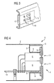
- FIG. 4 shows a cross section through a connection region 4 of a fully assembled computer housing 1 according to an embodiment of the invention.
- the computer housing 1 comprises a chassis 2 with an opening 8, which is integrated into a front side 3, for the connection area 4.
- a panel 10 is arranged in front of the front side 3.
- the aperture 10 has in the illustrated embodiment, two openings 11 through which two ports, in the embodiment audio ports 6, are passed therethrough. For example, these can be so-called 3.5 mm jack sockets.
- a seal 12 is arranged, which consists in the embodiment of an elastic, electrically conductive material.
- the seal 12 contacts the front ends of the tabs 9 and thus establishes an electrical connection between the chassis 2 and the seal 12. Furthermore, the seal 12 closes positively in the region of the openings 11 with the audio terminals 6, so that the computer housing 1 is electromagnetically sealed in the connection area 4.
- the housing of the audio terminals 6 are additionally connected to an electrical ground potential, so that over a collar portion of the audio terminals 6, an additional ground contact between the computer case 1 and the seal 12 is made.
- the audio connections 6 are arranged directly on a motherboard 14, so that the assembly work for the computer system is minimized.
- a motherboard 14 After inserting the motherboard 12 in the chassis 2, only a matching front panel 10 with seal 12 mounted thereon must be placed on the front side 3 of the chassis 2 in order to produce both the electrical function of the terminals 6 and the EMC tightness of the computer housing 1. In this way, the manufacture and installation of a computer system is made particularly simple.
- operating elements can also be provided in the connection region 4. Examples of such controls are buttons or switches for turning on the computer system or switching the computer system to a power-saving state.
- display elements may also be provided in the form of status displays, for example LCD or LED displays.
- the aperture 10 does not necessarily have to have openings 11 in the terminal area 4. Instead of the openings 11 then flexible or translucent elements of the diaphragm 10 can occur, which allow operation of the controls or displaying status information through the aperture 10 therethrough. Even in such an embodiment, both the assembly of the computer housing 1, as well as its electromagnetic tightness by using a seal 12 in the connection area 4 is simplified or improved.
- the invention is not limited to an application in the region of a front side 3 of a chassis 2.
- An application is possible in virtually every area of a veneered housing that is to be easily shielded electromagnetically.
Description
Die Erfindung betrifft ein Computergehäuse, umfassend ein Chassis aus einem elektrisch leitfähigen Material mit wenigstens einer Öffnung und eine Blende aus einem elektrisch nicht leitfähigen Material im Bereich der wenigstens einen Öffnung.The invention relates to a computer housing, comprising a chassis made of an electrically conductive material having at least one opening and a diaphragm made of an electrically non-conductive material in the region of the at least one opening.
Computergehäuse der oben genannten Art sind vielfach bekannt. Insbesondere weisen die meisten Desktopcomputer im vorderen Bereich ein Anschlussfeld auf, über das Zusatzgeräte wie beispielsweise Mikrofone, Kopfhörer oder Ein-/Ausgabegeräte angeschlossen werden können. Dafür geeignete Anschlüsse sind in der Regel im vorderen Bereich einer Hauptplatine des Computersystems oder auf einer gesonderten Platine angeordnet, die im vorderen Bereich des Computersystems angeordnet ist. Die einzelnen Anschlüsse oder deren Zuleitungen korrespondieren mit einer oder mehreren Öffnungen in dem Chassis des Computergehäuses.Computer cases of the above type are widely known. In particular, most front-end desktop computers have a connector panel that allows you to attach accessories such as microphones, headphones, or input / output devices. Appropriate connections are usually arranged in the front region of a motherboard of the computer system or on a separate board, which is arranged in the front region of the computer system. The individual terminals or their leads correspond to one or more openings in the chassis of the computer housing.
Um eine ansprechende Gestaltung des Computersystems zu ermöglichen und auch um die einzelnen Anschlüsse des Computergehäuses leichter identifizieren zu können, weisen die meisten Computergehäuse eine zusätzlich Blende auf, in die die verschiedenen Baugruppen und Anschlüsse eines Computersystems einheitlich integriert sind. Solche Blenden bestehen in der Regel aus Kunststoff, was eine besonders leichte Bearbeitung und ansprechende Gestaltung ermöglicht.In order to enable an appealing design of the computer system and also to be able to more easily identify the individual connections of the computer housing, most computer housings have an additional panel in which the various components and connections of a computer system are uniformly integrated. Such panels are usually made of plastic, which allows a particularly easy editing and attractive design.
Moderne Computer arbeiten mit sehr hohen Arbeitsfrequenzen, teilweise im Bereich von mehreren Gigahertz, so dass von ihnen nicht unerhebliche elektromagnetische Störfelder ausgehen. Entsprechend den Bestimmungen zur elektromagnetischen Verträglichkeit (EMV) muss die von einem Computersystem ausgesandte elektromagnetische Strahlung in geeigneter Weise abgeschirmt werden. Hierzu dient in erster Linie ein Chassis aus einem elektrisch leitfähigen Material, insbesondere Stahlblech, das als Farraday'scher Käfig wirkt.Modern computers operate at very high operating frequencies, sometimes in the region of several gigahertz, so that they emanate considerable electromagnetic interference fields. According to the regulations on electromagnetic compatibility (EMC), the information transmitted by a computer system must be Electromagnetic radiation are shielded in a suitable manner. This primarily serves a chassis made of an electrically conductive material, in particular steel sheet, which acts as a Farraday cage.
Die Notwendigkeit, Öffnungen in dem Computergehäuse zur Durchführung von Anschlüssen und anderen Bedienelementen vorzusehen, vermindert jedoch deren elektromagnetische Dichtigkeit. Aus diesem Grund sind im Bereich von Öffnungen eines Chassis, insbesondere dem vorderen Anschlussbereich, üblicherweise zusätzliche Abschirmblenden aus gebogenem Blech auf die Vorderwand des Computergehäuses aufgenietet oder aufgeschraubt, um dessen elektromagnetische Dichtigkeit an dieser Stelle wieder herzustellen.However, the need to provide openings in the computer housing for passing ports and other controls reduces their electromagnetic tightness. For this reason, in the region of openings of a chassis, in particular the front connection area, usually additional screens made of bent sheet metal are riveted or screwed onto the front wall of the computer housing to restore its electromagnetic tightness at this point.
Nachteilig an dem beschriebenen Gehäusekonzept ist jedoch, dass diese zusätzlichen Abschirmblenden an die spezifischen Ein- und Ausgabeelemente eines jeden Computertyps angepasst werden müssen. Darüber hinaus entsteht durch die Verwendung und Installation zusätzlicher Komponenten ein nicht unerheblicher Mehraufwand bei der Herstellung und dem Zusammenbau derartiger Computersysteme.A disadvantage of the described housing concept, however, is that these additional shielding screens must be adapted to the specific input and output elements of each type of computer. In addition, the use and installation of additional components creates a significant additional effort in the manufacture and assembly of such computer systems.
Aus der
Aufgabe der vorliegenden Erfindung ist es, ein Computergehäuse zu beschreiben, bei dem die elektromagnetische Dichtigkeit auf besonders einfache Weise ohne die Verwendung zusätzlicher Abschirmblenden hergestellt werden kann.The object of the present invention is to describe a computer housing in which the electromagnetic tightness can be produced in a particularly simple manner without the use of additional shielding screens.
Die zugrunde liegende Aufgabe wird erfindungsgemäß durch ein Computergehäuse, umfassend ein Chassis aus einem elektrisch leitfähigen Material mit wenigstens einer Öffnung in einer ersten Seite des Chassis und eine Blende (10) aus einem elektrisch nicht leitfähigen Material im Bereich der wenigstens einen Öffnung gelöst, wobei die Blende vor der ersten Seite des Chassis angeordnet ist.The underlying object is achieved by a computer housing comprising a chassis made of an electrically conductive material having at least one opening in a first side of the chassis and a diaphragm (10) made of an electrically non-conductive material in the region of at least one opening, wherein the Aperture is located in front of the first side of the chassis.
Dabei weist das Chassis im Bereich der Öffnung wenigstens eine, in Richtung der Blende abstehende Lasche auf und auf einer dem Chassis zugewandten Seite der Blende ist wenigstens eine elektrisch leitfähige Dichtung im Bereich der Öffnung des Chassis angeordnet, wobei die Dichtung im elektrischen Kontakt mit der wenigstens einen Lasche steht, um eine elektrische Schirmung des Computergehäuses im Bereich der Öffnung zu bewirken.In this case, the chassis in the region of the opening at least one, projecting in the direction of the aperture tab and on a side facing the chassis of the aperture at least one electrically conductive seal in the region of the opening of the chassis is arranged, wherein the seal in electrical contact with the at least a tab is provided to cause an electrical shield of the computer housing in the region of the opening.
Durch die Verwendung einer abstehenden Lasche einerseits und einer elektrisch leitfähigen Dichtung andererseits kann ein sicherer elektrischer Kontakt zwischen dem Chassis und der Dichtung der Blende hergestellt werden. Durch Aufbringen der elektrisch leitfähigen Dichtung auf die Blende wirkt die vor der Seite des Chassis angeordnete Blende selbst als Abschirmelement, so dass auf die Verwendung zusätzlicher Abschirmblenden verzichtet werden kann.By using a protruding tab on the one hand and an electrically conductive seal on the other hand, a secure electrical contact between the chassis and the seal of the panel can be made. By applying the electrically conductive seal on the panel arranged in front of the side of the chassis aperture itself acts as a shielding, so that it can be dispensed with the use of additional shielding.
Gemäß einer vorteilhaften Ausgestaltung umfasst die elektrisch leitfähige Dichtung ein elastisches Schaumstoffteil mit einer elektrisch leitfähigen Oberfläche oder ein elektrisch leitfähiges Polymer-Material. Durch Verwendung einer elastischen Dichtung können Fertigungstoleranzen durch die Flexibilität der Dichtung in einfacher Weise ausgeglichen werden.According to an advantageous embodiment, the electrically conductive seal comprises an elastic foam part with an electrically conductive surface or an electrically conductive polymer material. By using an elastic seal manufacturing tolerances can be compensated by the flexibility of the seal in a simple manner.
Gemäß einer weiteren vorteilhaften Ausgestaltung sind in der Blende und in der elektrisch leitfähigen Dichtung wenigstens eine Öffnung zur Durchführung eines Anschlusses, eines Bedienelementes oder eines Bedienelementes angeordnet, wobei die elektrisch leitfähige Dichtung formschlüssig mit diesem abschließt. Durch ein Vorsehen von Öffnungen in der Blende und der elektrisch leitfähigen Dichtung können Anschlüsse, Anzeigeelemente beziehungsweise Bedienelemente auf einfache Weise durch die Frontblende hindurch geführt werden, so dass diese für einen Benutzer von vorne zugänglich sind. Gleichzeitig kann durch die formschlüssige Gestaltung der elektrisch leitfähigen Dichtung die elektromagnetische Dichtigkeit des Gehäuses bewahrt werden.According to a further advantageous embodiment, at least one opening for the passage of a connection, an operating element or a control element are arranged in the diaphragm and in the electrically conductive seal, wherein the electrically conductive seal positively closes with this. By providing openings in the panel and the electrically conductive seal connections, display elements or controls can be performed in a simple manner through the front panel, so that they are accessible to a user from the front. At the same time, the electromagnetic tightness of the housing can be preserved by the positive design of the electrically conductive seal.
Gemäß einer weiteren vorteilhaften Ausgestaltung sind in der Blende und in der elektrisch leitfähigen Dichtung eine Mehrzahl von Öffnungen für eine Mehrzahl von Anschlüssen, Anzeigelementen und/oder Bedienelementen angeordnet und in dem Chassis ist eine einzelne Öffnung zum Durchführen dieser Mehrzahl vorgesehen. Durch die Verwendung einer einzelnen Öffnung auf Seiten des Chassis und einer Mehrzahl von Öffnungen auf Seiten der Blende zum Durchführen einer Mehrzahl von Anschlüssen, Anzeigelementen und/oder Bedienelementen kann ein einzelner Chassistyp für eine Vielzahl von Computersystemen mit unterschiedlichen Anschlusselementen im Bereich der Blende eingesetzt werden. Auf diese Weise ist eine einfache Variation des Computergehäuses durch Anpassen der Blende allein möglich.According to a further advantageous embodiment, a plurality of openings for a plurality of terminals, display elements and / or controls are arranged in the panel and in the electrically conductive seal and in the chassis, a single opening for performing this plurality is provided. By using a single opening on the side of the chassis and a plurality of apertures on the side of the bezel for passing a plurality of terminals, indicators and / or controls, a single type of chassis for a plurality of computer systems having different terminal elements in the region of the bezel can be used. In this way, a simple variation of the computer case by adjusting the aperture alone is possible.
Weitere vorteilhafte Ausgestaltungen der Erfindung sind in den Unteransprüchen angegeben.Further advantageous embodiments of the invention are specified in the subclaims.
Die Erfindung wird nachfolgend anhand von Ausführungsbeispielen unter Bezugnahme auf Figuren näher erläutert. In den Figuren zeigen:
- Figur 1
- eine perspektivische Ansicht eines Computergehäuse gemäß dem Stand der Technik,
Figur 2- eine perspektivische Ansicht eines Computergehäuses gemäß einer Ausgestaltung der Erfindung,
- Figur 3
- eine perspektivische Ansicht einer Blende mit einer darauf angeordneten elektrisch leitfähigen Dichtung und
Figur 4- einen Querschnitt durch ein Computergehäuse gemäß einer Ausgestaltung der Erfindung.
- FIG. 1
- a perspective view of a computer housing according to the prior art,
- FIG. 2
- a perspective view of a computer housing according to an embodiment of the invention,
- FIG. 3
- a perspective view of a panel with an electrically conductive seal and arranged thereon
- FIG. 4
- a cross section through a computer case according to an embodiment of the invention.
Die USB-Anschlüsse 5 und die Audioanschlüsse 6 des Anschlussbereiches 4 sind im Ausführungsbeispiel hinter einer Abschirmblende 7 angeordnet, deren Öffnungen genau an die Anschlüsse angepasst sind. Die Abschirmblende 7 verdeckt eine Öffnung in der Vorderseite 3 des Chassis 2, und schließt so das Chassis 2 nach vorne hin ab. Um die EMV-Dichtigkeit des Computergehäuses 1 im Bereich des Anschlussbereiches sicherzustellen, ist die Abschirmblende 7 aus einem elektrisch leitfähigen Material, beispielsweise Stahlblech, geformt. Die Abschirmblende 7 ist im dargestellten Ausführungsbeispiel auf die Vorderseite 3 geschraubt oder genietet, wodurch eine sichere elektrische Verbindung zwischen dem Chassis 2 und der Abschirmblende 7 hergestellt wird.In the exemplary embodiment, the
Vor der Abschirmblende 7 mit den darin integrierten Anschlüssen 5 und 6 wird im montierten Zustand des Computergehäuses 1 eine weitere Frontblende angeordnet, die im in der
Anstelle einer Abschirmblende 7 umfasst das Computergehäuse 1 gemäß der
Die Dichtung 12 ist in einem Bereich 13 der Blende 10 angeordnet, der mit der Öffnung 8 des Chassis 2 korrespondiert. Wird die Blende 10 im Bereich der Vorderseite 3 des Computergehäuses angeordnet, kontaktieren die Laschen 9 somit die Dichtung 12 und stellen eine elektrische Verbindung zwischen diesen Elementen her. Auf diese Weise wird die EMV-Dichtigkeit des Gehäuses 1 durch ein Aufsetzen der Blende 10 mit der darauf aufgebrachten Dichtung 12 für den Anschlussbereich 4 hergestellt.The
Aus der Vorderseite 3 des Chassis 2 sind zwei Laschen 9 herausgebogen, die fast bis an die Rückseite der Blende 10 heranreichen. Auf der Rückseite der Blende 10, also der den Laschen 9 zugewandten Seite, ist eine Dichtung 12 angeordnet, die im Ausführungsbeispiel aus einem elastischen, elektrisch leitfähigen Material besteht. Die Dichtung 12 kontaktiert die vorderen Enden der Laschen 9 und stellt somit eine elektrische Verbindung zwischen dem Chassis 2 und der Dichtung 12 her. Des Weiteren schließt die Dichtung 12 im Bereich der Öffnungen 11 formschlüssig mit den Audioanschlüssen 6 ab, so dass das Computergehäuse 1 im Anschlussbereich 4 elektromagnetisch abgedichtet ist.From the front side 3 of the
In einer vorteilhaften Ausgestaltung sind die Gehäuse der Audioanschlüsse 6 zusätzlich mit einem elektrischen Massepotential verbunden, so dass über einen Kragenbereich der Audioanschlüsse 6 ein zusätzlicher Massekontakt zwischen dem Computergehäuse 1 und der Dichtung 12 hergestellt wird.In an advantageous embodiment, the housing of the
Im in der
Anstelle der USB-Anschlüsse 5 oder der Audioanschlüsse 6 können in dem Anschlussbereich 4 auch Bedienelemente vorgesehen sein. Beispiele für solche Bedienelemente sind Taster oder Schalter zum Einschalten des Computersystems oder zum Schalten des Computersystems in einen Energiesparzustand. Darüber hinaus können auch Anzeigeelemente in der Form von Statusanzeigen, beispielsweise LCD- oder LED-Anzeigen vorgesehen sein.Instead of the
In diesem Fall muss die Blende 10 nicht notwendigerweise über Öffnungen 11 in dem Anschlussbereich 4 verfügen. Anstelle der Öffnungen 11 können dann flexible oder durchscheinende Elemente der Blende 10 treten, die eine Bedienung der Bedienelemente beziehungsweise ein Anzeigen von Statusinformationen durch die Blende 10 hindurch gestatten. Auch in einer solchen Ausgestaltung wird sowohl die Montage des Computergehäuses 1, als auch dessen elektromagnetische Dichtigkeit durch Verwendung einer Dichtung 12 in dem Anschlussbereich 4 vereinfacht beziehungsweise verbessert.In this case, the
Selbstverständlich ist die Erfindung nicht auf eine Anwendung im Bereich einer Vorderseite 3 eines Chassis 2 beschränkt. Eine Anwendung ist in praktisch jedem Bereich eines verblendeten Gehäuses möglich, das auf einfache Weise elektromagnetisch abgeschirmt werden soll.Of course, the invention is not limited to an application in the region of a front side 3 of a
- 11
- Computergehäusecomputer case
- 22
- Chassischassis
- 33
- Vorderseitefront
- 44
- Anschlussbereichterminal area
- 55
- USB-AnschlussUSB port
- 66
- AudioanschlussAudio connection
- 77
- Abschirmblechshield
- 88th
- Öffnungopening
- 99
- Lascheflap
- 1010
- Blendecover
- 1111
- Öffnungopening
- 1212
- Dichtungpoetry
- 1313
- BereichArea
- 1414
- Hauptplatinemotherboard
Claims (8)
- Computer housing (1) comprising a chassis (2) which is composed of an electrically conductive material and has at least one opening (8) in a first side (3) of the chassis (2) and a panel (10) which is arranged in front of the first side (3) of the chassis (2) and in the region of the at least one opening (8), characterized in that the panel (10) is produced from an electrically non-conductive material, the chassis (2) has at least one lug (9), which is bent out of the first side (3) and projects forwards in the direction of the panel (10), in the region of the opening (8), and at least one electrically conductive seal (12) is arranged in the region of the opening (8) in the chassis (2) on a side of the panel (10) which faces the chassis (2), wherein the seal (12) is in electrical contact with the at least one lug (9) in order to create an electrical shield for the computer housing (1) in the region of the opening (8).
- Computer housing (1) according to Claim 1, characterized in that the electrically conductive seal (12) comprises an elastic foam part with an electrically conductive surface or an electrically conductive polymer material.
- Computer housing (1) according to Claim 1 or 2, characterized in that at least one operator control element is provided in the region of the opening (8) and the panel (10) is designed to be at least partially flexible in the region of the at least one operator control element, so that the operator control element can be operated through the panel (10).
- Computer housing (1) according to one of Claims 1 to 3, characterized in that at least one indicator element is provided in the region of the opening (8) and the panel (10) is designed to be at least partially transparent in the region of the at least one indicator element, so that the indicator element can be read through the panel (10).
- Computer housing (1) according to one of Claims 1 to 4, characterized in that at least one opening (11) through which a connection (5, 6), an indicator element or an operator control element can be routed is arranged in the panel (10) and the electrically conductive seal (12), wherein the electrically conductive seal (12) terminates in a form-fitting manner with the connection (5, 6), the indicator element or the operator control element.
- Computer housing (1) according to Claim 5, characterized in that a plurality of openings (11) for a plurality of connections (5, 6), indicator elements and/or operator control elements are arranged in the panel (10) and the electrically conductive seal (12), and a single opening (8) through which the plurality of connections (5, 6), indicator elements or operator control elements can be routed is provided in the chassis (2).
- Computer housing (1) according to one of Claims 3 to 6, characterized in that the opening (8) in the chassis (2) and the panel (10) are arranged on a front face (3) of the computer housing (1), so that at least one connection (5, 6), one indicator element and/or one operator control element are/is accessible to a user of the computer system (1).
- Computer housing (1) according to one of Claims 1 to 6, characterized in that the opening (8) in the chassis (2) is surrounded by a plurality of lugs (9) which establish electrical contact between the seal (12) and the chassis (2) at various points.
Applications Claiming Priority (1)
| Application Number | Priority Date | Filing Date | Title |
|---|---|---|---|
| DE200710030123 DE102007030123B3 (en) | 2007-06-29 | 2007-06-29 | computer case |
Publications (3)
| Publication Number | Publication Date |
|---|---|
| EP2017692A2 EP2017692A2 (en) | 2009-01-21 |
| EP2017692A3 EP2017692A3 (en) | 2011-03-09 |
| EP2017692B1 true EP2017692B1 (en) | 2013-08-28 |
Family
ID=39493574
Family Applications (1)
| Application Number | Title | Priority Date | Filing Date |
|---|---|---|---|
| EP20080103506 Expired - Fee Related EP2017692B1 (en) | 2007-06-29 | 2008-04-11 | Computer enclosure |
Country Status (2)
| Country | Link |
|---|---|
| EP (1) | EP2017692B1 (en) |
| DE (1) | DE102007030123B3 (en) |
Families Citing this family (1)
| Publication number | Priority date | Publication date | Assignee | Title |
|---|---|---|---|---|
| DE102010031035B3 (en) * | 2010-07-07 | 2012-01-05 | Siemens Aktiengesellschaft | Personal computer, has electromagnetically shielded housing with opening, and universal serial bus port that is surrounded by electromagnetically shielded space in retracted state with flap closed |
Family Cites Families (8)
| Publication number | Priority date | Publication date | Assignee | Title |
|---|---|---|---|---|
| US5347430A (en) * | 1993-04-06 | 1994-09-13 | Dell Usa, L.P. | Computer chassis construction |
| EP0655882B1 (en) * | 1993-11-16 | 1996-08-21 | Digital Equipment Corporation | EMI shielding for electronic components |
| US6339536B1 (en) * | 1999-11-10 | 2002-01-15 | Dell Usa, L.P. | I/O shield bracket assembly |
| US6307756B1 (en) * | 2000-06-27 | 2001-10-23 | Hon Hai Precision Ind. Co., Ltd. | Connector holder with conductive shield |
| US20020088628A1 (en) * | 2001-01-10 | 2002-07-11 | Chen Shih Hui | EMI protective I/O connector holder plate |
| DE10228633B4 (en) * | 2002-06-26 | 2006-12-21 | Fujitsu Siemens Computers Gmbh | Device for protection against electrostatic discharge and electromagnetic influences |
| US7411784B2 (en) * | 2004-05-07 | 2008-08-12 | Rackable Systems, Inc. | Electromagnetic interference shield for I/O ports |
| DE102005056953B3 (en) * | 2005-11-29 | 2007-04-12 | Fujitsu Siemens Computers Gmbh | Computer housing has screen plate with opening for terminal with protective element connected to seal by ideal break point to open up required access |
-
2007
- 2007-06-29 DE DE200710030123 patent/DE102007030123B3/en not_active Expired - Fee Related
-
2008
- 2008-04-11 EP EP20080103506 patent/EP2017692B1/en not_active Expired - Fee Related
Also Published As
| Publication number | Publication date |
|---|---|
| DE102007030123B3 (en) | 2008-09-18 |
| EP2017692A3 (en) | 2011-03-09 |
| EP2017692A2 (en) | 2009-01-21 |
Similar Documents
| Publication | Publication Date | Title |
|---|---|---|
| DE602005005754T2 (en) | A liquid crystal display device and mobile information terminal having a liquid crystal display device | |
| DE102006049567B4 (en) | Shielding structure for information technology equipment | |
| EP2639943B1 (en) | Electric motor | |
| DE102008046983A1 (en) | Vehicle interior illumination lamp unit | |
| DE102007023787B4 (en) | Electromagnetic shield for displays | |
| DE102014100142A1 (en) | Flood-proof connector construction for a low-resistance cable between ground pin and housing | |
| EP1731841A1 (en) | Cooking hob with operating device | |
| EP1788665A2 (en) | Electrical connecting device | |
| DE102018113724B4 (en) | Interface arrangement, computer system and method for assembling an interface arrangement | |
| DE3335664C2 (en) | ||
| DE202014100679U1 (en) | Electrical / electronic installation device | |
| EP2017692B1 (en) | Computer enclosure | |
| EP1976072B1 (en) | Bus connector with at least two cable connections for bus lines | |
| DE102015108105A1 (en) | Shielding structure of an electronic device unit and control panel housing | |
| DE102005056953B3 (en) | Computer housing has screen plate with opening for terminal with protective element connected to seal by ideal break point to open up required access | |
| EP2453541B1 (en) | Electric switching gear assembly | |
| WO2011101101A2 (en) | Covering frame for installation devices | |
| DE102009043656B4 (en) | I / O panel for a chassis of a computer system and arrangement of chassis and I / O panel | |
| DE3843948C2 (en) | Electrical device with connector | |
| EP1863329B1 (en) | EMC insulation | |
| EP0618763A1 (en) | Shielded casing for electric elements with plug for internal and external cable connection | |
| DE102020105881B4 (en) | Electrical / electronic installation device surrounded by a cover frame | |
| EP2664065B1 (en) | Control device for a vehicle module | |
| DE102009025984A1 (en) | Housing for accommodating electronic circuit of industrial personal computer, has circuit carrier provided with various parameters and input/output connections arranged on circuit carrier that is installed in housing | |
| DE102005050545A1 (en) | Between glass contact element |
Legal Events
| Date | Code | Title | Description |
|---|---|---|---|
| PUAI | Public reference made under article 153(3) epc to a published international application that has entered the european phase |
Free format text: ORIGINAL CODE: 0009012 |
|
| AK | Designated contracting states |
Kind code of ref document: A2 Designated state(s): AT BE BG CH CY CZ DE DK EE ES FI FR GB GR HR HU IE IS IT LI LT LU LV MC MT NL NO PL PT RO SE SI SK TR |
|
| AX | Request for extension of the european patent |
Extension state: AL BA MK RS |
|
| PUAL | Search report despatched |
Free format text: ORIGINAL CODE: 0009013 |
|
| AK | Designated contracting states |
Kind code of ref document: A3 Designated state(s): AT BE BG CH CY CZ DE DK EE ES FI FR GB GR HR HU IE IS IT LI LT LU LV MC MT NL NO PL PT RO SE SI SK TR |
|
| AX | Request for extension of the european patent |
Extension state: AL BA MK RS |
|
| RIC1 | Information provided on ipc code assigned before grant |
Ipc: G11B 33/14 20060101ALI20110202BHEP Ipc: G06F 1/18 20060101AFI20080616BHEP |
|
| RAP1 | Party data changed (applicant data changed or rights of an application transferred) |
Owner name: FUJITSU TECHNOLOGY SOLUTIONS INTELLECTUAL PROPERTY |
|
| 17P | Request for examination filed |
Effective date: 20110826 |
|
| AKX | Designation fees paid |
Designated state(s): DE FR GB |
|
| GRAP | Despatch of communication of intention to grant a patent |
Free format text: ORIGINAL CODE: EPIDOSNIGR1 |
|
| INTG | Intention to grant announced |
Effective date: 20130429 |
|
| GRAS | Grant fee paid |
Free format text: ORIGINAL CODE: EPIDOSNIGR3 |
|
| GRAA | (expected) grant |
Free format text: ORIGINAL CODE: 0009210 |
|
| AK | Designated contracting states |
Kind code of ref document: B1 Designated state(s): FR GB |
|
| RBV | Designated contracting states (corrected) |
Designated state(s): FR GB |
|
| REG | Reference to a national code |
Ref country code: GB Ref legal event code: FG4D Free format text: NOT ENGLISH Ref country code: DE Ref legal event code: R108 |
|
| REG | Reference to a national code |
Ref country code: DE Ref legal event code: R108 Effective date: 20130828 |
|
| PLBE | No opposition filed within time limit |
Free format text: ORIGINAL CODE: 0009261 |
|
| STAA | Information on the status of an ep patent application or granted ep patent |
Free format text: STATUS: NO OPPOSITION FILED WITHIN TIME LIMIT |
|
| 26N | No opposition filed |
Effective date: 20140530 |
|
| REG | Reference to a national code |
Ref country code: FR Ref legal event code: PLFP Year of fee payment: 9 |
|
| PGFP | Annual fee paid to national office [announced via postgrant information from national office to epo] |
Ref country code: GB Payment date: 20160422 Year of fee payment: 9 |
|
| PGFP | Annual fee paid to national office [announced via postgrant information from national office to epo] |
Ref country code: FR Payment date: 20160422 Year of fee payment: 9 |
|
| GBPC | Gb: european patent ceased through non-payment of renewal fee |
Effective date: 20170411 |
|
| REG | Reference to a national code |
Ref country code: FR Ref legal event code: ST Effective date: 20171229 |
|
| PG25 | Lapsed in a contracting state [announced via postgrant information from national office to epo] |
Ref country code: FR Free format text: LAPSE BECAUSE OF NON-PAYMENT OF DUE FEES Effective date: 20170502 |
|
| PG25 | Lapsed in a contracting state [announced via postgrant information from national office to epo] |
Ref country code: GB Free format text: LAPSE BECAUSE OF NON-PAYMENT OF DUE FEES Effective date: 20170411 |