EP2453121A2 - Structure for attaching exhaust gas sensor - Google Patents
Structure for attaching exhaust gas sensor Download PDFInfo
- Publication number
- EP2453121A2 EP2453121A2 EP11188020A EP11188020A EP2453121A2 EP 2453121 A2 EP2453121 A2 EP 2453121A2 EP 11188020 A EP11188020 A EP 11188020A EP 11188020 A EP11188020 A EP 11188020A EP 2453121 A2 EP2453121 A2 EP 2453121A2
- Authority
- EP
- European Patent Office
- Prior art keywords
- exhaust gas
- gas sensor
- exhaust
- port
- attaching
- Prior art date
- Legal status (The legal status is an assumption and is not a legal conclusion. Google has not performed a legal analysis and makes no representation as to the accuracy of the status listed.)
- Granted
Links
- 238000002485 combustion reaction Methods 0.000 claims abstract description 37
- 238000011144 upstream manufacturing Methods 0.000 claims abstract description 16
- 239000007789 gas Substances 0.000 claims description 210
- QVGXLLKOCUKJST-UHFFFAOYSA-N atomic oxygen Chemical compound [O] QVGXLLKOCUKJST-UHFFFAOYSA-N 0.000 claims description 19
- 239000001301 oxygen Substances 0.000 claims description 19
- 229910052760 oxygen Inorganic materials 0.000 claims description 19
- 239000000446 fuel Substances 0.000 claims description 7
- 238000002347 injection Methods 0.000 claims description 6
- 239000007924 injection Substances 0.000 claims description 6
- 230000005540 biological transmission Effects 0.000 description 7
- 238000001514 detection method Methods 0.000 description 7
- 239000007787 solid Substances 0.000 description 5
- MCMNRKCIXSYSNV-UHFFFAOYSA-N Zirconium dioxide Chemical compound O=[Zr]=O MCMNRKCIXSYSNV-UHFFFAOYSA-N 0.000 description 4
- 230000004913 activation Effects 0.000 description 4
- 238000006243 chemical reaction Methods 0.000 description 3
- 230000000694 effects Effects 0.000 description 3
- BASFCYQUMIYNBI-UHFFFAOYSA-N platinum Chemical compound [Pt] BASFCYQUMIYNBI-UHFFFAOYSA-N 0.000 description 3
- 239000011148 porous material Substances 0.000 description 3
- 239000003638 chemical reducing agent Substances 0.000 description 2
- 230000003247 decreasing effect Effects 0.000 description 2
- 230000001133 acceleration Effects 0.000 description 1
- 230000001154 acute effect Effects 0.000 description 1
- 230000002411 adverse Effects 0.000 description 1
- 238000006073 displacement reaction Methods 0.000 description 1
- 230000002708 enhancing effect Effects 0.000 description 1
- 239000002828 fuel tank Substances 0.000 description 1
- 229910052697 platinum Inorganic materials 0.000 description 1
- 239000007784 solid electrolyte Substances 0.000 description 1
- 239000000725 suspension Substances 0.000 description 1
- 229920003002 synthetic resin Polymers 0.000 description 1
- 239000000057 synthetic resin Substances 0.000 description 1
- 239000010409 thin film Substances 0.000 description 1
Images


Classifications
-
- F—MECHANICAL ENGINEERING; LIGHTING; HEATING; WEAPONS; BLASTING
- F01—MACHINES OR ENGINES IN GENERAL; ENGINE PLANTS IN GENERAL; STEAM ENGINES
- F01N—GAS-FLOW SILENCERS OR EXHAUST APPARATUS FOR MACHINES OR ENGINES IN GENERAL; GAS-FLOW SILENCERS OR EXHAUST APPARATUS FOR INTERNAL COMBUSTION ENGINES
- F01N13/00—Exhaust or silencing apparatus characterised by constructional features ; Exhaust or silencing apparatus, or parts thereof, having pertinent characteristics not provided for in, or of interest apart from, groups F01N1/00 - F01N5/00, F01N9/00, F01N11/00
- F01N13/008—Mounting or arrangement of exhaust sensors in or on exhaust apparatus
-
- F—MECHANICAL ENGINEERING; LIGHTING; HEATING; WEAPONS; BLASTING
- F01—MACHINES OR ENGINES IN GENERAL; ENGINE PLANTS IN GENERAL; STEAM ENGINES
- F01N—GAS-FLOW SILENCERS OR EXHAUST APPARATUS FOR MACHINES OR ENGINES IN GENERAL; GAS-FLOW SILENCERS OR EXHAUST APPARATUS FOR INTERNAL COMBUSTION ENGINES
- F01N13/00—Exhaust or silencing apparatus characterised by constructional features ; Exhaust or silencing apparatus, or parts thereof, having pertinent characteristics not provided for in, or of interest apart from, groups F01N1/00 - F01N5/00, F01N9/00, F01N11/00
- F01N13/08—Other arrangements or adaptations of exhaust conduits
- F01N13/10—Other arrangements or adaptations of exhaust conduits of exhaust manifolds
-
- F—MECHANICAL ENGINEERING; LIGHTING; HEATING; WEAPONS; BLASTING
- F02—COMBUSTION ENGINES; HOT-GAS OR COMBUSTION-PRODUCT ENGINE PLANTS
- F02B—INTERNAL-COMBUSTION PISTON ENGINES; COMBUSTION ENGINES IN GENERAL
- F02B61/00—Adaptations of engines for driving vehicles or for driving propellers; Combinations of engines with gearing
- F02B61/02—Adaptations of engines for driving vehicles or for driving propellers; Combinations of engines with gearing for driving cycles
-
- F—MECHANICAL ENGINEERING; LIGHTING; HEATING; WEAPONS; BLASTING
- F02—COMBUSTION ENGINES; HOT-GAS OR COMBUSTION-PRODUCT ENGINE PLANTS
- F02B—INTERNAL-COMBUSTION PISTON ENGINES; COMBUSTION ENGINES IN GENERAL
- F02B77/00—Component parts, details or accessories, not otherwise provided for
- F02B77/08—Safety, indicating or supervising devices
- F02B77/085—Safety, indicating or supervising devices with sensors measuring combustion processes, e.g. knocking, pressure, ionization, combustion flame
- F02B77/086—Sensor arrangements in the exhaust, e.g. for temperature, misfire, air/fuel ratio, oxygen sensors
-
- F—MECHANICAL ENGINEERING; LIGHTING; HEATING; WEAPONS; BLASTING
- F02—COMBUSTION ENGINES; HOT-GAS OR COMBUSTION-PRODUCT ENGINE PLANTS
- F02D—CONTROLLING COMBUSTION ENGINES
- F02D41/00—Electrical control of supply of combustible mixture or its constituents
- F02D41/02—Circuit arrangements for generating control signals
- F02D41/14—Introducing closed-loop corrections
- F02D41/1438—Introducing closed-loop corrections using means for determining characteristics of the combustion gases; Sensors therefor
- F02D41/1439—Introducing closed-loop corrections using means for determining characteristics of the combustion gases; Sensors therefor characterised by the position of the sensor
-
- F—MECHANICAL ENGINEERING; LIGHTING; HEATING; WEAPONS; BLASTING
- F01—MACHINES OR ENGINES IN GENERAL; ENGINE PLANTS IN GENERAL; STEAM ENGINES
- F01N—GAS-FLOW SILENCERS OR EXHAUST APPARATUS FOR MACHINES OR ENGINES IN GENERAL; GAS-FLOW SILENCERS OR EXHAUST APPARATUS FOR INTERNAL COMBUSTION ENGINES
- F01N2560/00—Exhaust systems with means for detecting or measuring exhaust gas components or characteristics
- F01N2560/02—Exhaust systems with means for detecting or measuring exhaust gas components or characteristics the means being an exhaust gas sensor
- F01N2560/025—Exhaust systems with means for detecting or measuring exhaust gas components or characteristics the means being an exhaust gas sensor for measuring or detecting O2, e.g. lambda sensors
-
- F—MECHANICAL ENGINEERING; LIGHTING; HEATING; WEAPONS; BLASTING
- F01—MACHINES OR ENGINES IN GENERAL; ENGINE PLANTS IN GENERAL; STEAM ENGINES
- F01N—GAS-FLOW SILENCERS OR EXHAUST APPARATUS FOR MACHINES OR ENGINES IN GENERAL; GAS-FLOW SILENCERS OR EXHAUST APPARATUS FOR INTERNAL COMBUSTION ENGINES
- F01N2590/00—Exhaust or silencing apparatus adapted to particular use, e.g. for military applications, airplanes, submarines
- F01N2590/04—Exhaust or silencing apparatus adapted to particular use, e.g. for military applications, airplanes, submarines for motorcycles
Definitions
- the present invention relates to a structure for attaching an exhaust gas sensor.
- an exhaust gas sensor having no heater structure should be configured to be capable of securing a temperature needed for its reaction as early as possible, and thus of starting to detect oxygen with higher accuracy as early as possible.
- a problem to be solved is to enhance the accuracy of detecting oxygen while securing the heat resistance of the exhaust gas sensor.
- Examples of the prior art include an example in which a part of an exhaust pipe is divided into two passages.
- One of the two passages serves as an exhaust gas main discharge passage having a larger cross section, while the other of the two passages serves as an exhaust gas sensor attachment passage having a smaller cross section.
- the exhaust gas main discharge passage is provided with a quantity-of-flow control valve.
- Control is performed by use of a controller unit and an actuator in a way that: until the temperature of an element of the exhaust gas sensor reaches an activation temperature, the quantity-of-flow control valve is shut off to increase the quantity of the exhaust gas flowing to the exhaust gas sensor attachment passage and to thereby raise the temperature of the element; once the temperature of the element of the exhaust gas sensor becomes equal to or higher than a temperature which thermally deteriorates the element, the quantity-of-flow control valve is opened to decrease the quantity of the exhaust gas flowing to the exhaust gas sensor attachment passage and to thereby inhibit the rise in the temperature of the element (see Japanese examined Utility Model publication No. Hei 1-43461 , for example).
- An object of the present invention is to provide means which allows an exhaust gas sensor having no heater structure to start detecting oxygen with higher accuracy as early as possible after an internal combustion engine starts, without depending on the control of the quantity of flow of the exhaust gas as in the example described above; and which enhances the accuracy of detecting oxygen while securing the heat resistance of the exhaust gas sensor.
- the present invention is one which have solved the problems described above, and a first aspect of the invention relates to a structure for attaching an exhaust gas sensor, characterized in that an exhaust gas collecting groove (64) extending in a direction of a flow of an exhaust gas is provided to an inner wall of an exhaust port (40) between an outlet port (43) and an exhaust pipe attachment portion (74) in a cylinder head (31) of an internal combustion engine (2), the outlet port (43) being an upstream entrance to the exhaust port (40), the exhaust pipe attachment portion (74) being an exhaust port exit, and the exhaust gas sensor (62) is attached in a way that a front end portion of the exhaust gas sensor (62) is situated in the rear of the exhaust gas collecting groove (64).
- a second aspect of the invention is the structure for attaching an exhaust gas sensor of the first aspect, characterized in that a base of an element protecting cap (71) of the exhaust gas sensor (62) is situated in an exhaust gas sensor attachment hole (63), and a front end portion of the element protecting cap is situated in a gas passage of the exhaust port (40).
- a third aspect of the invention is the structure for attaching an exhaust gas sensor of the second aspect, characterized in that a passage shape of the exhaust port (40) is curved from the outlet port (43), which is an opening and closing port of an exhaust valve (44), toward the exhaust pipe attachment portion (74) in a side view ( Fig. 3 ) extending in a direction of a cylinder axial line (C), the passage shape of the exhaust port (40) is also curved in a left-right direction when viewed in the direction of the cylinder axial line (C) ( Fig. 4 ), and the exhaust gas collecting groove (64) is provided in a curved exhaust port's internal-side inner wall surface (77) and the exhaust gas sensor (62) is attached thereto.
- a fourth aspect of the invention is the structure for attaching an exhaust gas sensor of any one of the first and second aspects, characterized in that the exhaust gas collecting groove (64) is formed, extending upstream and downstream of a holding portion (79) for holding a valve guide (45) (a vicinity of a neck portion (80) of the exhaust port), which is provided to the exhaust port (40).
- a fifth aspect of the invention is the structure for attaching an exhaust gas sensor of the fourth aspect, characterized in that the exhaust gas collecting groove (64) is formed in a way that an rear-extended imaginary termination portion (75), which is formed by extending a wall surface of the exhaust gas collecting groove (64) in a downstream direction, almost coincides with an oxygen concentration detector (69) of the exhaust gas sensor (62).
- a sixth aspect of the invention is the structure for attaching an exhaust gas sensor of the fifth aspect, characterized in that, when the internal combustion engine (2) is started, the internal combustion engine (2) is controlled by controlling an ignition timing and a fuel injection amount with an amount of the intake air kept constant.
- a seventh aspect of the invention is the structure for attaching an exhaust gas sensor of any one of the fourth and fifth aspects, characterized in that the exhaust gas sensor (62) is placed in the groove in a way that the exhaust gas sensor (62) projects from a downstream side to an upstream side with respect to a passage center line (E) of the exhaust port (40).
- An eighth aspect of the invention is the structure for attaching an exhaust gas sensor of the seventh aspect, characterized in that an axial line (S) of the exhaust gas sensor (62) is arranged to be displaced by a predetermined dimension (d) from the passage center line (E) of the exhaust port (40) toward an inner part of a curved portion of the exhaust port (40).
- the exhaust gas is guided to the exhaust gas sensor (62) by the exhaust gas collecting groove (64).
- the exhaust gas sensor (62) can be activated more early in the initial stage of the operation of the internal combustion engine (2).
- the degree at which the oxygen concentration detector (69) is exposed to the passage inside the port can be reduced by use of the exhaust gas guiding effect to the exhaust gas collecting groove (64).
- the heat resistance of the exhaust gas sensor (62) is enhanced because the detector (69) is less exposed to the exhaust gas at high temperature and pressure.
- the exhaust gas sensor (62) is provided in the side part of the curved portion ( Fig. 3 ), that is to say, the curved exhaust port's internal-side inner wall surface (77).
- the exhaust gas sensor (62) is less exposed to the exhaust gas at the high temperature and pressure, and the heat resistance of the exhaust gas sensor (62) can be enhanced.
- the exhaust gas sensor (62) can be activated more early.
- the stream of the exhaust gas flowing inside the exhaust gas collecting groove (64) directly hits on the oxygen concentration detector (69) of the exhaust gas sensor (62) and is thus prevented from bypassing and getting downstream of the exhaust gas sensor (62).
- the detection accuracy of the detector of the exhaust gas sensor (62) can be enhanced.
- the time that it takes for the reaction to start during the operation start can be reduced even in the internal combustion engine (2) equipped with no amount-of-intake-air controller (IACV: an idle air control valve).
- IACV an idle air control valve
- the flow of the exhaust gas into the inside of the oxygen concentration detector (69) can be enhanced, and accordingly the detection accuracy is enhanced.
- the axial line (S) of the exhaust gas sensor (62) is arranged to be displaced by the predetermined dimension (d) from the passage center line (E) of the exhaust port (40) toward the inner part of the curve of the exhaust port (40).
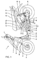
- Fig. 1 is a left side view of a motorcycle 1 of an embodiment of the present invention.
- This motorcycle 1 includes a power unit 4 into which an internal combustion engine 2 and a power transmission system 3 are integrated.
- the internal combustion engine 2 is a single-cylinder four-stroke-cycle internal combustion engine.
- the power unit 4 is installed in the motorcycle 1 with a crankshaft 5 directed in the left-right direction.
- paired left and right front forks 9 pivotally supporting a front wheel 8 are steerably pivotally supported by a head pipe 7 situated in a front end portion of a vehicle body frame 6 with a steering stem 10 in between.
- a steering handlebar 11 is attached to a top portion of the steering stem 10.
- a single main frame 12 as a front portion of the vehicle body frame 6 extends obliquely downward from the head pipe 7, and is subsequently bent to extend rearward horizontally.
- a step floor 13 on which for the driver to put his/her feet is placed on a horizontal portion of the main frame 12.
- a rear end portion of the main frame 12 is joined to a middle portion of a cross frame 14 in the left-right direction.
- the cross frame 14 extends in the left-right direction.
- Paired left and right pivot plates 15 are joined to the cross frame 14.
- the power unit 4 is supported by a suspension link 16, which is installed among the pivot plates 15 and the power unit 4, in a way that the power unit 4 is swingable in the vertical direction.
- a front end portion of a left rear frame 17L and a front end portion of a right rear frame 17R are joined to the respective left and right end portions of the cross frame 14.
- the left and right rear frames 17L, 17R extend obliquely upward from the cross frame 14, and is subsequently bent to extend with decreased inclination.
- Halfway portions of the respective left and right rear frames 17L, 17R extending obliquely upward are connected and joined together by a cross member 18.
- a front half portion of the right rear frame 17R is higher than a front half portion of the left rear frame 17L.
- Rear ends of the respective left and right rear frames 17L, 17R are connected and joined together by a connecting member 19 which horizontally extends in the vehicle widthwise direction.
- a seat 20 including a driver's seat and a pillion seat is provided above the left and right rear frames 17L, 17R.
- a storage box 21 is provided between the left and right rear frames 17L, 17R under a front portion of the seat 20.
- a fuel tank 22 is provided under a rear portion of the seat 20.
- the vehicle body frame 6 is covered with a body cover 23 made of a synthetic resin.
- a rear portion of the power unit 4 is supported by the left rear frame 17L with a rear cushion 24 in between.
- a rear wheel 25 is pivotally supported by a rear end portion of the power transmission system 3.
- a front fender 26 is provided over the front wheel 8
- a rear fender 27 is provided over the rear wheel 25.
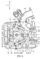
- Fig. 2 is a left side view of the power unit 4.
- the power unit 4 is formed of the internal combustion engine 2 and the power transmission system 3.
- a crankcase 28 of the internal combustion engine 2 and a front portion of a case 29 of the power transmission system 3 are connected together.
- the crankshaft 5 penetrates an intermediate wall between the internal combustion engine 2 and the power transmission system 3.
- the internal combustion engine 2 is formed of a cylinder block 30, a cylinder head 31 and a cylinder head cover 32 which are sequentially connected together in this order from the rear to the front from the crankcase 28.
- the power transmission system 3 is formed of a V-belt continuously variable transmission 33 and a gear speed reducer 34.
- a shaft of a rearmost gear of the gear speed reducer 34 is a rear wheel shaft 35, and the rear wheel 25 ( Fig. 1 ) is integrally attached to the rear wheel shaft 35.
- Fig. 3 is a view of a longitudinal cross section of a part of the internal combustion engine 2, which includes the cylinder head 31 and its vicinities, the part being viewed from the left side.
- Fig. 3 is a view taken along a direction of a cylinder axis line C.
- Descriptions of the drawings will be provided with directions of the arrows Fr, Up, Dn in the drawing denoting frontward, upward and downward, respectively.
- the cylinder head 31 is connected to the cylinder block 30 by use of bolts 36.
- the cylinder head cover 32 is connected to the cylinder head 31 by use of bolts, which are not illustrated.
- a curved intake port 39 is formed in an upper portion of the cylinder head 31.
- An upstream end of the intake port 39 is opened upward, and a downstream end thereof is opened to a combustion chamber 38.
- a curved exhaust port 40 is formed in a lower portion of the cylinder head 31. An upstream end of the exhaust port 40 is opened to the combustion chamber 38, and a downstream end thereof is opened downward.
- an intake valve 42 for opening and closing an inlet port 41 of the combustion chamber 38 and an exhaust valve 44 for opening and closing an outlet port 43 of the combustion chamber 38 are slidably fitted into their respective valve guides 45.
- An intake pipe 46 is connected to an opening of the upstream end of the intake port 39.
- a throttle body 37 ( Fig. 2 ) is connected to an upstream end of the intake pipe 46.
- a fuel injection valve 47 is attached to the intake pipe 46. A front end of the fuel injection valve 47 faces the intake port 39.
- An exhaust pipe 48 ( Fig. 1 ) is connected to a downstream end of the exhaust port 40.
- the intake and exhaust valves 42, 44 biased in their valve-closing directions by respective valve springs 49 are driven to open and close by a valve system 51 inside a valve chamber 50 which is formed by the cylinder head 31 and the cylinder head cover 32.
- a single cam shaft 52 is horizontally, rotatably and pivotally supported by ball bearings in the valve chamber 50.
- An intake cam 53 and an exhaust cam 54 are formed integrally with the cam shaft 52.
- An intake rocker shaft 55 is provided to the cylinder head 31 in front of and above the cam shaft 52.
- An exhaust rocker shaft 56 is provided to the cylinder head 31 in front of and under the cam shaft 52.
- An intake rocker arm 57 and an exhaust rocker arm 58 are swingably pivotally supported by the intake rocker shaft 55 and the exhaust rocker shaft 56, respectively.
- Rollers 59 in contact with the cams 53, 54 are pivotally supported by ends of the rocker arms 57, 58, respectively.
- Contact members 60 are attached to the other ends of the rocker arms 57, 58, respectively. These contact members 60 are in contact with top portions of the intake and exhaust valves 42, 44, respectively. The contact members 60 open and close the respective intake and exhaust valves 42, 44 in accordance with the revolution of the cam shaft 52.
- An attachment hole 63 for an exhaust gas sensor 62 is opened in an inner wall surface of the exhaust port 40 in a portion close to the downstream end. A front end portion of the exhaust gas sensor 62 is exposed to the inside of the exhaust port 40.
- An exhaust gas collecting groove 64 extending from an upstream portion of the exhaust port 40 to the attachment hole 63 is provided in the inner wall of the exhaust port 40. Descriptions will be later provided for how this groove works.
- Fig. 4 is an arrow view taken along the line IV-IV of Fig. 3 .
- Fig. 4 is a view of the cylinder head 31 viewed from the rear in the direction of the cylinder axis line C.
- Fig. 3 is a cross-sectional view taken along the line III-III of Fig. 4 .
- the directions indicated with the arrows Up, L, R in the drawing represent upward, leftward and rightward, respectively.
- Fig. 4 is a view of the cylinder head 31 viewed from the combustion chamber 38.
- a surface around the combustion chamber 38 is a contact surface 65 with the cylinder block 30.
- the inlet and outlet ports 41, 43 of the combustion chamber 38 are shown in the drawing.
- the intake port 39 communicates with the inlet port 41, and the exhaust port 40 communicates with the outlet port 43.
- the exhaust gas sensor 62 is attached to the cylinder head 31 in a way that the exhaust gas sensor 62 faces the downstream portion of the exhaust port 40.
- the shape of the passage of the exhaust port 40 is curved from the outlet port 43 toward an exhaust pipe attachment portion 74 in the side view of the internal combustion engine 2 ( Fig. 3 ) taken along the direction of the cylinder axis line C.
- the shape of the passage of the exhaust port 40 is curved in the left-right direction in the view ( Fig. 4 ) in the direction of the cylinder axis direction C.
- the exhaust gas collecting groove 64 extending in a direction of the flow of the exhaust gas is provided in the inner wall of the exhaust port 40 between the outlet port 43 and the exhaust pipe attachment portion 74.
- the exhaust gas sensor attachment hole 63 is provided, and the exhaust gas sensor 62 is attached to the exhaust gas sensor attachment hole 63, in a way that the front end portion of the exhaust gas sensor 62 is located in the back of the exhaust gas collecting groove 64. For this reason, the exhaust gas is guided to the exhaust gas sensor 62 by the exhaust gas collecting groove 64. Thus, the exhaust gas sensor 62 can be activated more early when the internal combustion engine is started.
- Fig. 5 is an arrow view viewed in a direction of the arrow V of Fig. 4 .
- An uppermost portion of this drawing represents the contact surface 65 with the cylinder block 30, and a lowermost portion of this drawing represents a contact surface 66 with the cylinder head cover 32.
- An exhaust pipe attachment flange 67 is marked with an imaginary line. The exhaust gas sensor 62 is attached, directed to the exhaust port 40.
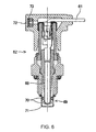
- Fig. 6 is a longitudinal sectional view of the exhaust gas sensor 62.
- a sensor element 68 is placed in the middle portion of the exhaust gas sensor 62.
- the sensor element 68 is obtained by: forming a solid electrolyte essentially containing zirconia (ZrO 2 ) into a closed-end tube; and adhering a platinum (Pt) thin film to the outer surface of the resultant closed-end tube.
- the sensor element 68 is designed in a way that the atmosphere is introduced into the inside of the sensor element 68 while the outer portion of the sensor element 68 is exposed to the exhaust gas.
- a front end portion of the exhaust gas sensor 62 is an oxygen concentration detector 69.
- An element protecting cap 71 having numerous pores 70 is provided to the front end portion of the exhaust gas sensor 62.
- the exhaust gas enters the inside of the exhaust gas sensor 62 through the pores 70, and comes into contact with the outer periphery of the sensor element 68.
- the atmosphere is introduced through an atmosphere introducing port 72 via a filter 73.
- An electromotive force is produced due to the difference in oxygen concentration between the inside and outside of the element 68.
- the detection of the oxygen concentration is achieved by detecting the electromotive force.
- an electric cord 61 connected to the inside and outside of the element is extended out from an end portion of the exhaust gas sensor 62. It is possible to know a change in the oxygen concentration through a sudden change in the electromotive force which takes place around a theoretical air-fuel ratio.
- a condition in which the exhaust gas sensor 62 detects the oxygen concentration most accurately in other words, a temperature of the element 68 in an activated state, is not less than 300°C, but not greater than 900°C. For this reason, the temperature of the element 68 is required to be raised as early as possible, especially, when the internal combustion engine is started. In addition, the element 68 is required not to be heated to an excessively high temperature during the operation.
- Fig. 7 is a cross-sectional view taken along the line VII-VII of Fig. 3 .
- Fig. 7 is a view of the cross section of the exhaust port 40, the exhaust gas sensor 62 and their vicinities shown in Fig. 4 , the cross section being viewed from the back of Fig. 4 .
- This is a magnified cross-sectional view showing an attachment portion to which the exhaust gas sensor 62 is attached in detail.
- the illustration of the exhaust valve 44 is omitted.
- the outlet port 43 is seen in the upstream portion of the exhaust port 40.
- the main stream of the exhaust gas flows in a direction of the arrow F.
- the front end of the detector 69 of the exhaust gas sensor 62 is exposed to the exhaust gas stream.
- the exhaust gas gets to the outer surface of the element 68 ( Fig. 6 ) through the multiple pores 70 which are provided in the element protecting cap 71.
- the exhaust gas collecting groove 64 and the exhaust gas sensor 62 are provided to a curved exhaust port's internal-side inner wall surface 77.
- the exhaust gas at high temperature and pressure flows at a high speed along a curved exhaust port's external-side inner wall surface 78 which is away from the exhaust gas collecting groove 64 and the exhaust gas sensor 62.
- the exhaust gas sensor 62 is less exposed to the exhaust gas at the high temperature and pressure, and the heat resistance of the exhaust gas sensor 62 is accordingly enhanced.
- Figs. 8 and 9 are each a solid model view of the exhaust port 40. Although the exhaust port 40 is a space having no solid existence, Figs. 8 and 9 are perspective views of a model which is produced as if the exhaust port 40 had a solid existence.
- Fig. 8 shows a view in a direction of the arrow VIII of Fig. 7 .
- Fig. 9 is a view in a direction of the arrow IX of Fig. 8 .
- the exhaust gas collecting groove 64 is formed in a way that a rearward-extended imaginary termination end 75 of the groove, which is formed by extending the wall surface of the groove in the downstream direction, almost coincides with the oxygen concentration detector 69 of the exhaust gas sensor 62. For this reason, the exhaust gas flowing in the exhaust gas collecting groove 64 directly hits on the detector 69 of the exhaust gas sensor 62. This makes it possible to prevent the exhaust gas from bypassing and getting downstream of the exhaust gas sensor 62. Accordingly, the detection accuracy of the exhaust gas sensor 62 can be enhanced.
- the exhaust gas sensor 62 is placed, directed to the exhaust port 40 in a way that the exhaust gas sensor 62 project from the downstream side to the upstream side with respect to a passage center line E of the exhaust port 40.
- the flow direction F of the main stream of the exhaust gas coincides with the passage center line E of the exhaust port 40.
- an angle ⁇ between the flow direction F of the main stream of the exhaust gas and an axial line S of the exhaust gas sensor 62 is acute. This makes it possible to improve the flow of the exhaust gas into the inside of the detector 69 of the exhaust gas sensor 62, and accordingly to enhance the detection accuracy.
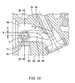
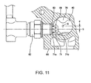
- Fig. 10 is a magnified cross-sectional view of the exhaust port 40 and its vicinities shown in Fig. 3 .
- Fig. 11 is a cross-sectional view taken along the line XI-XI of Fig. 10 .
- the lowermost portion of each of Figs. 10 and 11 represents the contact surface 65 with the cylinder block 30.
- the front end of the exhaust gas sensor 62 is exposed to the inside of the exhaust port 40.
- the exhaust gas collecting groove 64 is formed, extending upstream and downstream of a neck portion 80 (see Fig. 8 as well) where the exhaust port 40 becomes narrower due to a valve guide holding portion 79. Because even the exhaust gas whose speed slows down due to the neck portion 80 flows into the exhaust gas collecting groove 64, it is possible to activate the sensor more early in an initial stage of the start.
- a base 71a of the element protecting cap 71 of the exhaust gas sensor 62 is situated in the exhaust gas sensor attachment hole 63, and a front end portion 71b of the element protecting cap 71 is situated in the exhaust gas passage of the exhaust port 40.
- the purpose of this arrangement is to reduce the exposure of the detector 69 to the exhaust gas at the high temperature and pressure by decreasing the degree at which the detector 69 is exposed to the gas passage in the exhaust port 40 by use of the effect of guiding the exhaust gas, and to enable the oxygen concentration to be detected while enhancing the heat resistance of the exhaust gas sensor 62.
- the axial line S of the exhaust gas sensor 62 is arranged to be displaced by a dimension d from the passage center line E of the exhaust port 40 toward an inner part of the curve of the exhaust port 40, that is to say, toward the contact surface 65 with the cylinder block 30.
- the exhaust gas sensor 62 does not obstruct the flow of the exhaust gas because: the flow speed of the exhaust gas is fast; and the exhaust accordingly flows in the outer part of the curved portion in a direction of the arrow H in Fig. 10 .
- the embodiment controls the ignition timing and the fuel injection amount with the amount of the intake air kept constant, when the internal combustion engine 2 is started. To put it specifically, the embodiment makes it possible to reduce the time that it takes for the reaction to start, even in a case where the control is carried out by only increasing the advance angle for the ignition timing and the fuel injection amount without carrying out the intake air control nor the like when the engine is started, in a structure from which the acceleration of the engine warm-up by increasing the engine speed through the warming-up operation cannot be expected.
Abstract
Description
- The present invention relates to a structure for attaching an exhaust gas sensor.
- It has been desired that an exhaust gas sensor having no heater structure (a heaterless oxygen sensor) should be configured to be capable of securing a temperature needed for its reaction as early as possible, and thus of starting to detect oxygen with higher accuracy as early as possible. On the other hand, because the exhaust gas sensor is exposed to a high-temperature exhaust gas during the operation, a problem to be solved is to enhance the accuracy of detecting oxygen while securing the heat resistance of the exhaust gas sensor.
- Examples of the prior art include an example in which a part of an exhaust pipe is divided into two passages. One of the two passages serves as an exhaust gas main discharge passage having a larger cross section, while the other of the two passages serves as an exhaust gas sensor attachment passage having a smaller cross section. The exhaust gas main discharge passage is provided with a quantity-of-flow control valve. Control is performed by use of a controller unit and an actuator in a way that: until the temperature of an element of the exhaust gas sensor reaches an activation temperature, the quantity-of-flow control valve is shut off to increase the quantity of the exhaust gas flowing to the exhaust gas sensor attachment passage and to thereby raise the temperature of the element; once the temperature of the element of the exhaust gas sensor becomes equal to or higher than a temperature which thermally deteriorates the element, the quantity-of-flow control valve is opened to decrease the quantity of the exhaust gas flowing to the exhaust gas sensor attachment passage and to thereby inhibit the rise in the temperature of the element (see Japanese examined Utility Model publication No.
Hei 1-43461 - An object of the present invention is to provide means which allows an exhaust gas sensor having no heater structure to start detecting oxygen with higher accuracy as early as possible after an internal combustion engine starts, without depending on the control of the quantity of flow of the exhaust gas as in the example described above; and which enhances the accuracy of detecting oxygen while securing the heat resistance of the exhaust gas sensor.
- The present invention is one which have solved the problems described above, and a first aspect of the invention relates to a structure for attaching an exhaust gas sensor, characterized in that an exhaust gas collecting groove (64) extending in a direction of a flow of an exhaust gas is provided to an inner wall of an exhaust port (40) between an outlet port (43) and an exhaust pipe attachment portion (74) in a cylinder head (31) of an internal combustion engine (2), the outlet port (43) being an upstream entrance to the exhaust port (40), the exhaust pipe attachment portion (74) being an exhaust port exit, and the exhaust gas sensor (62) is attached in a way that a front end portion of the exhaust gas sensor (62) is situated in the rear of the exhaust gas collecting groove (64).
- A second aspect of the invention is the structure for attaching an exhaust gas sensor of the first aspect, characterized in that a base of an element protecting cap (71) of the exhaust gas sensor (62) is situated in an exhaust gas sensor attachment hole (63), and a front end portion of the element protecting cap is situated in a gas passage of the exhaust port (40).
- A third aspect of the invention is the structure for attaching an exhaust gas sensor of the second aspect, characterized in that a passage shape of the exhaust port (40) is curved from the outlet port (43), which is an opening and closing port of an exhaust valve (44), toward the exhaust pipe attachment portion (74) in a side view (
Fig. 3 ) extending in a direction of a cylinder axial line (C), the passage shape of the exhaust port (40) is also curved in a left-right direction when viewed in the direction of the cylinder axial line (C) (Fig. 4 ), and the exhaust gas collecting groove (64) is provided in a curved exhaust port's internal-side inner wall surface (77) and the exhaust gas sensor (62) is attached thereto. - A fourth aspect of the invention is the structure for attaching an exhaust gas sensor of any one of the first and second aspects, characterized in that the exhaust gas collecting groove (64) is formed, extending upstream and downstream of a holding portion (79) for holding a valve guide (45) (a vicinity of a neck portion (80) of the exhaust port), which is provided to the exhaust port (40).
- A fifth aspect of the invention is the structure for attaching an exhaust gas sensor of the fourth aspect, characterized in that the exhaust gas collecting groove (64) is formed in a way that an rear-extended imaginary termination portion (75), which is formed by extending a wall surface of the exhaust gas collecting groove (64) in a downstream direction, almost coincides with an oxygen concentration detector (69) of the exhaust gas sensor (62).
- A sixth aspect of the invention is the structure for attaching an exhaust gas sensor of the fifth aspect, characterized in that, when the internal combustion engine (2) is started, the internal combustion engine (2) is controlled by controlling an ignition timing and a fuel injection amount with an amount of the intake air kept constant.
- A seventh aspect of the invention is the structure for attaching an exhaust gas sensor of any one of the fourth and fifth aspects, characterized in that the exhaust gas sensor (62) is placed in the groove in a way that the exhaust gas sensor (62) projects from a downstream side to an upstream side with respect to a passage center line (E) of the exhaust port (40).
- An eighth aspect of the invention is the structure for attaching an exhaust gas sensor of the seventh aspect, characterized in that an axial line (S) of the exhaust gas sensor (62) is arranged to be displaced by a predetermined dimension (d) from the passage center line (E) of the exhaust port (40) toward an inner part of a curved portion of the exhaust port (40).
- According to the first aspect of the invention, the exhaust gas is guided to the exhaust gas sensor (62) by the exhaust gas collecting groove (64). Thus, the exhaust gas sensor (62) can be activated more early in the initial stage of the operation of the internal combustion engine (2).
- According to the second aspect of the invention, the degree at which the oxygen concentration detector (69) is exposed to the passage inside the port can be reduced by use of the exhaust gas guiding effect to the exhaust gas collecting groove (64). In addition, the heat resistance of the exhaust gas sensor (62) is enhanced because the detector (69) is less exposed to the exhaust gas at high temperature and pressure.
- According to third aspect of the invention, the exhaust gas sensor (62) is provided in the side part of the curved portion (
Fig. 3 ), that is to say, the curved exhaust port's internal-side inner wall surface (77). Thus, the exhaust gas sensor (62) is less exposed to the exhaust gas at the high temperature and pressure, and the heat resistance of the exhaust gas sensor (62) can be enhanced. - According to the fourth aspect of the invention of, even the exhaust gas whose speed is relatively slow due to the neck portion (80) of the exhaust port (40) flows into the exhaust gas collecting groove (64) and is then sent to the exhaust gas sensor (62). Thus, the exhaust gas sensor (62) can be activated more early.
- According to the fifth aspect of the invention, the stream of the exhaust gas flowing inside the exhaust gas collecting groove (64) directly hits on the oxygen concentration detector (69) of the exhaust gas sensor (62) and is thus prevented from bypassing and getting downstream of the exhaust gas sensor (62). Thus, the detection accuracy of the detector of the exhaust gas sensor (62) can be enhanced.
- According to the sixth aspect of the invention, the time that it takes for the reaction to start during the operation start can be reduced even in the internal combustion engine (2) equipped with no amount-of-intake-air controller (IACV: an idle air control valve).
- According to the seventh aspect of the invention, the flow of the exhaust gas into the inside of the oxygen concentration detector (69) can be enhanced, and accordingly the detection accuracy is enhanced.
- According to the eighth aspect of the invention, the axial line (S) of the exhaust gas sensor (62) is arranged to be displaced by the predetermined dimension (d) from the passage center line (E) of the exhaust port (40) toward the inner part of the curve of the exhaust port (40). Thus, it is possible: to prevent the exhaust gas, which flows at a higher speed during the high output, from adversely affecting the performance of the internal combustion engine; and to effectively capture the exhaust gas, which flows toward the inner part of the curved portion during the operation start when the lower flow rate is low, by use of the exhaust gas collecting groove (64). Accordingly, the exhaust gas sensor (62) can be activated more early.
- Further features and advantages of the invention will become apparent from the following description with reference to the drawings, wherein:
-
Fig. 1 is a left side view of a motorcycle of an embodiment of the present invention; -
Fig. 2 is a left side view of a power unit of the motorcycle; -
Fig. 3 is a view of a longitudinal cross section of a part of an internal combustion engine, which includes a cylinder head and its vicinities, the part being viewed from the left side; -
Fig. 4 is an arrow view taken along the line IV-IV ofFig. 3 ; -
Fig. 5 is an arrow view viewed in a direction of the arrow V ofFig. 4 ; -
Fig. 6 is a longitudinal sectional view of an exhaust gas sensor; -
Fig. 7 is a cross-sectional view taken along the line VII-VII ofFig. 3 ; -
Fig. 8 is a solid model view of an exhaust port viewed in a direction of the arrow VIII ofFig. 7 ; -
Fig. 9 is a solid model view of the exhaust port viewed in a direction of the arrow IX ofFig. 8 ; -
Fig. 10 is a magnified cross-sectional view of the exhaust port and its vicinities shown inFig. 3 ; and -
Fig. 11 is a cross-sectional view taken along the line XI-XI ofFig. 10 . -
Fig. 1 is a left side view of a motorcycle 1 of an embodiment of the present invention. This motorcycle 1 includes apower unit 4 into which aninternal combustion engine 2 and apower transmission system 3 are integrated. Theinternal combustion engine 2 is a single-cylinder four-stroke-cycle internal combustion engine. Thepower unit 4 is installed in the motorcycle 1 with acrankshaft 5 directed in the left-right direction. - In this motorcycle 1, paired left and
right front forks 9 pivotally supporting afront wheel 8 are steerably pivotally supported by ahead pipe 7 situated in a front end portion of avehicle body frame 6 with asteering stem 10 in between. Asteering handlebar 11 is attached to a top portion of thesteering stem 10. - A single
main frame 12 as a front portion of thevehicle body frame 6 extends obliquely downward from thehead pipe 7, and is subsequently bent to extend rearward horizontally. Astep floor 13 on which for the driver to put his/her feet is placed on a horizontal portion of themain frame 12. - A rear end portion of the
main frame 12 is joined to a middle portion of across frame 14 in the left-right direction. Thecross frame 14 extends in the left-right direction. Paired left andright pivot plates 15 are joined to thecross frame 14. Thepower unit 4 is supported by asuspension link 16, which is installed among thepivot plates 15 and thepower unit 4, in a way that thepower unit 4 is swingable in the vertical direction. A front end portion of a leftrear frame 17L and a front end portion of a rightrear frame 17R are joined to the respective left and right end portions of thecross frame 14. - The left and right
rear frames cross frame 14, and is subsequently bent to extend with decreased inclination. Halfway portions of the respective left and rightrear frames cross member 18. A front half portion of the rightrear frame 17R is higher than a front half portion of the leftrear frame 17L. Rear ends of the respective left and rightrear frames member 19 which horizontally extends in the vehicle widthwise direction. - A
seat 20 including a driver's seat and a pillion seat is provided above the left and rightrear frames storage box 21 is provided between the left and rightrear frames seat 20. Afuel tank 22 is provided under a rear portion of theseat 20. Thevehicle body frame 6 is covered with abody cover 23 made of a synthetic resin. - A rear portion of the
power unit 4 is supported by the leftrear frame 17L with arear cushion 24 in between. Arear wheel 25 is pivotally supported by a rear end portion of thepower transmission system 3. Afront fender 26 is provided over thefront wheel 8, arear fender 27 is provided over therear wheel 25. -
Fig. 2 is a left side view of thepower unit 4. Thepower unit 4 is formed of theinternal combustion engine 2 and thepower transmission system 3. Acrankcase 28 of theinternal combustion engine 2 and a front portion of acase 29 of thepower transmission system 3 are connected together. Thecrankshaft 5 penetrates an intermediate wall between theinternal combustion engine 2 and thepower transmission system 3. Theinternal combustion engine 2 is formed of acylinder block 30, acylinder head 31 and acylinder head cover 32 which are sequentially connected together in this order from the rear to the front from thecrankcase 28. - The
power transmission system 3 is formed of a V-belt continuouslyvariable transmission 33 and agear speed reducer 34. A shaft of a rearmost gear of thegear speed reducer 34 is arear wheel shaft 35, and the rear wheel 25 (Fig. 1 ) is integrally attached to therear wheel shaft 35. -
Fig. 3 is a view of a longitudinal cross section of a part of theinternal combustion engine 2, which includes thecylinder head 31 and its vicinities, the part being viewed from the left side. In other words,Fig. 3 is a view taken along a direction of a cylinder axis line C. Descriptions of the drawings will be provided with directions of the arrows Fr, Up, Dn in the drawing denoting frontward, upward and downward, respectively. In the drawing, thecylinder head 31 is connected to thecylinder block 30 by use ofbolts 36. Thecylinder head cover 32 is connected to thecylinder head 31 by use of bolts, which are not illustrated. Acurved intake port 39 is formed in an upper portion of thecylinder head 31. An upstream end of theintake port 39 is opened upward, and a downstream end thereof is opened to acombustion chamber 38. Acurved exhaust port 40 is formed in a lower portion of thecylinder head 31. An upstream end of theexhaust port 40 is opened to thecombustion chamber 38, and a downstream end thereof is opened downward. - In the
cylinder head 31, anintake valve 42 for opening and closing aninlet port 41 of thecombustion chamber 38 and anexhaust valve 44 for opening and closing anoutlet port 43 of thecombustion chamber 38 are slidably fitted into their respective valve guides 45. Anintake pipe 46 is connected to an opening of the upstream end of theintake port 39. A throttle body 37 (Fig. 2 ) is connected to an upstream end of theintake pipe 46. Afuel injection valve 47 is attached to theintake pipe 46. A front end of thefuel injection valve 47 faces theintake port 39. An exhaust pipe 48 (Fig. 1 ) is connected to a downstream end of theexhaust port 40. - The intake and
exhaust valves valve system 51 inside avalve chamber 50 which is formed by thecylinder head 31 and thecylinder head cover 32. A single cam shaft 52 is horizontally, rotatably and pivotally supported by ball bearings in thevalve chamber 50. Anintake cam 53 and anexhaust cam 54 are formed integrally with the cam shaft 52. Anintake rocker shaft 55 is provided to thecylinder head 31 in front of and above the cam shaft 52. Anexhaust rocker shaft 56 is provided to thecylinder head 31 in front of and under the cam shaft 52. Anintake rocker arm 57 and anexhaust rocker arm 58 are swingably pivotally supported by theintake rocker shaft 55 and theexhaust rocker shaft 56, respectively.Rollers 59 in contact with thecams rocker arms Contact members 60 are attached to the other ends of therocker arms contact members 60 are in contact with top portions of the intake andexhaust valves contact members 60 open and close the respective intake andexhaust valves - An
attachment hole 63 for anexhaust gas sensor 62 is opened in an inner wall surface of theexhaust port 40 in a portion close to the downstream end. A front end portion of theexhaust gas sensor 62 is exposed to the inside of theexhaust port 40. An exhaustgas collecting groove 64 extending from an upstream portion of theexhaust port 40 to theattachment hole 63 is provided in the inner wall of theexhaust port 40. Descriptions will be later provided for how this groove works. -
Fig. 4 is an arrow view taken along the line IV-IV ofFig. 3 . In other words,Fig. 4 is a view of thecylinder head 31 viewed from the rear in the direction of the cylinder axis line C. Incidentally,Fig. 3 is a cross-sectional view taken along the line III-III ofFig. 4 . The directions indicated with the arrows Up, L, R in the drawing represent upward, leftward and rightward, respectively.Fig. 4 is a view of thecylinder head 31 viewed from thecombustion chamber 38. A surface around thecombustion chamber 38 is acontact surface 65 with thecylinder block 30. The inlet andoutlet ports combustion chamber 38 are shown in the drawing. Theintake port 39 communicates with theinlet port 41, and theexhaust port 40 communicates with theoutlet port 43. Theexhaust gas sensor 62 is attached to thecylinder head 31 in a way that theexhaust gas sensor 62 faces the downstream portion of theexhaust port 40. - In
Figs. 3 and4 , the shape of the passage of theexhaust port 40 is curved from theoutlet port 43 toward an exhaustpipe attachment portion 74 in the side view of the internal combustion engine 2 (Fig. 3 ) taken along the direction of the cylinder axis line C. In addition, the shape of the passage of theexhaust port 40 is curved in the left-right direction in the view (Fig. 4 ) in the direction of the cylinder axis direction C. In the drawing, the exhaustgas collecting groove 64 extending in a direction of the flow of the exhaust gas is provided in the inner wall of theexhaust port 40 between theoutlet port 43 and the exhaustpipe attachment portion 74. The exhaust gassensor attachment hole 63 is provided, and theexhaust gas sensor 62 is attached to the exhaust gassensor attachment hole 63, in a way that the front end portion of theexhaust gas sensor 62 is located in the back of the exhaustgas collecting groove 64. For this reason, the exhaust gas is guided to theexhaust gas sensor 62 by the exhaustgas collecting groove 64. Thus, theexhaust gas sensor 62 can be activated more early when the internal combustion engine is started. -
Fig. 5 is an arrow view viewed in a direction of the arrow V ofFig. 4 . An uppermost portion of this drawing represents thecontact surface 65 with thecylinder block 30, and a lowermost portion of this drawing represents acontact surface 66 with thecylinder head cover 32. An exhaustpipe attachment flange 67 is marked with an imaginary line. Theexhaust gas sensor 62 is attached, directed to theexhaust port 40. -
Fig. 6 is a longitudinal sectional view of theexhaust gas sensor 62. Asensor element 68 is placed in the middle portion of theexhaust gas sensor 62. Thesensor element 68 is obtained by: forming a solid electrolyte essentially containing zirconia (ZrO2) into a closed-end tube; and adhering a platinum (Pt) thin film to the outer surface of the resultant closed-end tube. Thesensor element 68 is designed in a way that the atmosphere is introduced into the inside of thesensor element 68 while the outer portion of thesensor element 68 is exposed to the exhaust gas. A front end portion of theexhaust gas sensor 62 is anoxygen concentration detector 69. Anelement protecting cap 71 havingnumerous pores 70 is provided to the front end portion of theexhaust gas sensor 62. The exhaust gas enters the inside of theexhaust gas sensor 62 through thepores 70, and comes into contact with the outer periphery of thesensor element 68. The atmosphere is introduced through anatmosphere introducing port 72 via afilter 73. An electromotive force is produced due to the difference in oxygen concentration between the inside and outside of theelement 68. The detection of the oxygen concentration is achieved by detecting the electromotive force. For the purpose of detecting the electromotive force of theexhaust gas sensor 62, anelectric cord 61 connected to the inside and outside of the element is extended out from an end portion of theexhaust gas sensor 62. It is possible to know a change in the oxygen concentration through a sudden change in the electromotive force which takes place around a theoretical air-fuel ratio. A condition in which theexhaust gas sensor 62 detects the oxygen concentration most accurately, in other words, a temperature of theelement 68 in an activated state, is not less than 300°C, but not greater than 900°C. For this reason, the temperature of theelement 68 is required to be raised as early as possible, especially, when the internal combustion engine is started. In addition, theelement 68 is required not to be heated to an excessively high temperature during the operation. -
Fig. 7 is a cross-sectional view taken along the line VII-VII ofFig. 3 .Fig. 7 is a view of the cross section of theexhaust port 40, theexhaust gas sensor 62 and their vicinities shown inFig. 4 , the cross section being viewed from the back ofFig. 4 . This is a magnified cross-sectional view showing an attachment portion to which theexhaust gas sensor 62 is attached in detail. The illustration of theexhaust valve 44 is omitted. Theoutlet port 43 is seen in the upstream portion of theexhaust port 40. The main stream of the exhaust gas flows in a direction of the arrow F. The front end of thedetector 69 of theexhaust gas sensor 62 is exposed to the exhaust gas stream. The exhaust gas gets to the outer surface of the element 68 (Fig. 6 ) through themultiple pores 70 which are provided in theelement protecting cap 71. - In
Fig. 7 , the exhaustgas collecting groove 64 and theexhaust gas sensor 62 are provided to a curved exhaust port's internal-sideinner wall surface 77. During the high-speed operation of theinternal combustion engine 2, the exhaust gas at high temperature and pressure flows at a high speed along a curved exhaust port's external-sideinner wall surface 78 which is away from the exhaustgas collecting groove 64 and theexhaust gas sensor 62. For this reason, during the high-speed operation, theexhaust gas sensor 62 is less exposed to the exhaust gas at the high temperature and pressure, and the heat resistance of theexhaust gas sensor 62 is accordingly enhanced. -
Figs. 8 and9 are each a solid model view of theexhaust port 40. Although theexhaust port 40 is a space having no solid existence,Figs. 8 and9 are perspective views of a model which is produced as if theexhaust port 40 had a solid existence.Fig. 8 shows a view in a direction of the arrow VIII ofFig. 7 .Fig. 9 is a view in a direction of the arrow IX ofFig. 8 . - In
Fig. 8 , the exhaustgas collecting groove 64 is formed in a way that a rearward-extendedimaginary termination end 75 of the groove, which is formed by extending the wall surface of the groove in the downstream direction, almost coincides with theoxygen concentration detector 69 of theexhaust gas sensor 62. For this reason, the exhaust gas flowing in the exhaustgas collecting groove 64 directly hits on thedetector 69 of theexhaust gas sensor 62. This makes it possible to prevent the exhaust gas from bypassing and getting downstream of theexhaust gas sensor 62. Accordingly, the detection accuracy of theexhaust gas sensor 62 can be enhanced. - In
Fig. 7 , theexhaust gas sensor 62 is placed, directed to theexhaust port 40 in a way that theexhaust gas sensor 62 project from the downstream side to the upstream side with respect to a passage center line E of theexhaust port 40. The flow direction F of the main stream of the exhaust gas coincides with the passage center line E of theexhaust port 40. In other words, inFig. 7 , an angle α between the flow direction F of the main stream of the exhaust gas and an axial line S of theexhaust gas sensor 62 is acute. This makes it possible to improve the flow of the exhaust gas into the inside of thedetector 69 of theexhaust gas sensor 62, and accordingly to enhance the detection accuracy. -
Fig. 10 is a magnified cross-sectional view of theexhaust port 40 and its vicinities shown inFig. 3 .Fig. 11 is a cross-sectional view taken along the line XI-XI ofFig. 10 . The lowermost portion of each ofFigs. 10 and11 represents thecontact surface 65 with thecylinder block 30. The front end of theexhaust gas sensor 62 is exposed to the inside of theexhaust port 40. - In
Fig. 10 , the exhaustgas collecting groove 64 is formed, extending upstream and downstream of a neck portion 80 (seeFig. 8 as well) where theexhaust port 40 becomes narrower due to a valveguide holding portion 79. Because even the exhaust gas whose speed slows down due to theneck portion 80 flows into the exhaustgas collecting groove 64, it is possible to activate the sensor more early in an initial stage of the start. - In
Fig. 11 , abase 71a of theelement protecting cap 71 of theexhaust gas sensor 62 is situated in the exhaust gassensor attachment hole 63, and afront end portion 71b of theelement protecting cap 71 is situated in the exhaust gas passage of theexhaust port 40. The purpose of this arrangement is to reduce the exposure of thedetector 69 to the exhaust gas at the high temperature and pressure by decreasing the degree at which thedetector 69 is exposed to the gas passage in theexhaust port 40 by use of the effect of guiding the exhaust gas, and to enable the oxygen concentration to be detected while enhancing the heat resistance of theexhaust gas sensor 62. - In
Figs. 10 and11 , the axial line S of theexhaust gas sensor 62 is arranged to be displaced by a dimension d from the passage center line E of theexhaust port 40 toward an inner part of the curve of theexhaust port 40, that is to say, toward thecontact surface 65 with thecylinder block 30. During the start of theinternal combustion engine 2, when the exhaust gas is flowing at a low speed, the stream of the exhaust gas flows toward the inner part of the curved portion in a direction of the arrow L inFig. 10 . This flow is effectively captured by the exhaustgas collecting groove 64. For this reason, the activation can be achieved early in the initial stage of the start. During the high output of theinternal combustion engine 2, theexhaust gas sensor 62 does not obstruct the flow of the exhaust gas because: the flow speed of the exhaust gas is fast; and the exhaust accordingly flows in the outer part of the curved portion in a direction of the arrow H inFig. 10 . - The embodiment controls the ignition timing and the fuel injection amount with the amount of the intake air kept constant, when the
internal combustion engine 2 is started. To put it specifically, the embodiment makes it possible to reduce the time that it takes for the reaction to start, even in a case where the control is carried out by only increasing the advance angle for the ignition timing and the fuel injection amount without carrying out the intake air control nor the like when the engine is started, in a structure from which the acceleration of the engine warm-up by increasing the engine speed through the warming-up operation cannot be expected. - As described above in detail, the embodiment brings about the following effects.
- (1) The exhaust gas is guided to the
exhaust gas sensor 62 by the exhaustgas collecting groove 64. Thus, theexhaust gas sensor 62 can be activated more early in the initial stage of the operation. - (2) Only the front end portion of the
element protecting cap 71 of theexhaust gas sensor 62 is situated in theexhaust port 40. Thus, the function of theexhaust gas sensor 62 can be fully employed, and the heat resistance of theexhaust gas sensor 62 can be enhanced by reducing the exposure of theexhaust gas sensor 62 to the exhaust gas at the high temperature and pressure. - (3) The
exhaust port 40 is shaped like a curve when viewed in the direction of the cylinder axial line C (Fig. 4 ) and the exhaustgas collecting groove 64, and theexhaust gas sensor 62 are provided in the internal-side inner wall of thecurved exhaust port 40. Thus, the exposure of theexhaust gas sensor 62 to the exhaust gas at the high temperature and pressure can be reduced, and the heat resistance of theexhaust gas sensor 62 can be accordingly enhanced. - (4) The gas whose speed is slowed down due to the valve
guide holding portion 79 also flows into the exhaustgas collecting groove 64 and is thus sent to theexhaust gas sensor 62, Thus, theexhaust gas sensor 62 can be activated more early. - (5) The exhaust
gas collecting groove 64 is formed in a way that the rearward-extendedimaginary termination portion 75 of the exhaustgas collecting groove 64, which is formed by extending the inner wall surface thereof in the downstream direction, almost coincides with theoxygen concentration detector 69 of theexhaust gas sensor 62. Thus, the exhaust gas flowing inside the exhaustgas collecting groove 64 concentratedly flows into thedetector 69 of theexhaust gas sensor 62, and it is accordingly possible to enhance the detection accuracy of thedetector 69 of theexhaust gas sensor 62. - (6) The time that it takes for the activation to start can be reduced even in the
internal combustion engine 2 which does not control the amount of the intake air. - (7) The
exhaust gas sensor 62 is placed in a way that the axial line S thereof tilts toward the upstream side with respect to the passage center line E of theexhaust port 40. Thus, the exhaust gas flows into the inside of theexhaust gas sensor 62 well, and the detection performance can be accordingly enhanced. - (8) The
exhaust gas sensor 62 is arranged to be displaced by the predetermined dimension d from the passage center line E of theexhaust port 40 toward an inner part of the curved portion of the exhaust port when viewed from the side (that is to say, toward thecontact surface 65 with the cylinder block 30). Thus, even during the start of theinternal combustion engine 2 when the exhaust gas is flowing at a low speed, the exhaustgas collecting groove 64 is capable of capturing the stream of the exhaust gas effectively, and the activation can be achieved early in the initial stage of the start. In addition, during the high output in which the flow speed of the exhaust gas is higher, theexhaust gas sensor 62 does not obstruct the flow of the exhaust gas. -
- 2
- internal combustion engine
- 31
- cylinder head
- 40
- exhaust port
- 43
- outlet port
- 44
- exhaust valve
- 45
- valve guide
- 62
- exhaust gas sensor
- 63
- exhaust gas sensor attachment hole
- 64
- exhaust gas collecting groove
- 69
- oxygen concentration detector
- 71
- element protecting cap
- 74
- exhaust pipe attachment portion
- 75
- rearward-extended imaginary termination portion of exhaust
gas collecting groove 64 - 77
- curved exhaust port's internal-side inner wall surface
- 78
- curved exhaust port's external-side inner wall surface
- 79
- valve guide holding portion
- 80
- neck portion of
exhaust port 40 - C
- cylinder axial line
- D
- dimension of displacement of exhaust gas sensor
- E
- passage center line of
exhaust port 40 - S
- axial line of
exhaust gas sensor 62
Claims (8)
- A structure for attaching an exhaust gas sensor, wherein
an exhaust gas collecting groove (64) extending in a direction of a flow of an exhaust gas is provided to an inner wall of an exhaust port (40) between an outlet port (43) and an exhaust pipe attachment portion (74) in a cylinder head (31) of an internal combustion engine (2), the outlet port (43) being an upstream entrance to the exhaust port (40), the exhaust pipe attachment portion (74) being an exhaust port exit, and
the exhaust gas sensor (62) is attached in a way that a front end portion of the exhaust gas sensor (62) is situated in the rear of the exhaust gas collecting groove (64). - The structure for attaching an exhaust gas sensor of claim 1, wherein
a base of an element protecting cap (71) of the exhaust gas sensor (62) is situated in an exhaust gas sensor attachment hole (63), and
a front end portion of the element protecting cap (71) is situated in a gas passage of the exhaust port (40). - The structure for attaching an exhaust gas sensor of claim 2, wherein
a passage shape of the exhaust port (40) is curved from the outlet port (43), which is an opening and closing port of an exhaust valve (44), toward the exhaust pipe attachment portion (74) in a side view (Fig. 3) extending in a direction of a cylinder axial line (C),
the passage shape of the exhaust port (40) is also curved in a left-right direction when viewed in the direction of the cylinder axial line (C) (Fig. 4), and
the exhaust gas collecting groove (64) is provided in a curved exhaust port's internal-side inner wall surface (77) and the exhaust gas sensor (62) is attached thereto. - The structure for attaching an exhaust gas sensor of any one of claims 1 and 2, wherein the exhaust gas collecting groove (64) is formed, extending upstream and downstream of a holding portion (79) for holding a valve guide (45) (a vicinity of a neck portion (80) of the exhaust port), which is provided to the exhaust port (40).
- The structure for attaching an exhaust gas sensor of claim 4, wherein the exhaust gas collecting groove (64) is formed in a way that an rear-extended imaginary termination portion (75), which is formed by extending a wall surface of the exhaust gas collecting groove (64) in a downstream direction, almost coincides with an oxygen concentration detector (69) of the exhaust gas sensor (62).
- The structure for attaching an exhaust gas sensor of claim 5, wherein, when the internal combustion engine (2) is started, the internal combustion engine (2) is controlled by controlling an ignition timing and a fuel injection amount with an amount of the intake air kept constant.
- The structure for attaching an exhaust gas sensor of any one of claims 4 and 5, wherein the exhaust gas sensor (62) is placed in the groove in a way that the exhaust gas sensor (62) projects from a downstream side to an upstream side with respect to a passage center line (E) of the exhaust port (40).
- The structure for attaching an exhaust gas sensor of claim 7, wherein an axial line (S) of the exhaust gas sensor (62) is arranged to be displaced by a predetermined dimension (d) from the passage center line (E) of the exhaust port (40) toward an inner part of a curved portion of the exhaust port (40).
Applications Claiming Priority (1)
| Application Number | Priority Date | Filing Date | Title |
|---|---|---|---|
| JP2010251442A JP5554687B2 (en) | 2010-11-10 | 2010-11-10 | Exhaust gas sensor mounting structure |
Publications (3)
| Publication Number | Publication Date |
|---|---|
| EP2453121A2 true EP2453121A2 (en) | 2012-05-16 |
| EP2453121A3 EP2453121A3 (en) | 2015-03-04 |
| EP2453121B1 EP2453121B1 (en) | 2018-05-30 |
Family
ID=45065694
Family Applications (1)
| Application Number | Title | Priority Date | Filing Date |
|---|---|---|---|
| EP11188020.9A Active EP2453121B1 (en) | 2010-11-10 | 2011-11-07 | Structure for attaching exhaust gas sensor |
Country Status (5)
| Country | Link |
|---|---|
| EP (1) | EP2453121B1 (en) |
| JP (1) | JP5554687B2 (en) |
| CN (1) | CN102465786B (en) |
| AU (1) | AU2011239341B2 (en) |
| ES (1) | ES2685078T3 (en) |
Cited By (2)
| Publication number | Priority date | Publication date | Assignee | Title |
|---|---|---|---|---|
| CN103674554A (en) * | 2013-10-25 | 2014-03-26 | 浙江吉利控股集团有限公司 | Automobile engine combustion chamber detection apparatus |
| EP2987973A1 (en) * | 2013-03-25 | 2016-02-24 | Honda Motor Co., Ltd. | Saddle type vehicle |
Families Citing this family (6)
| Publication number | Priority date | Publication date | Assignee | Title |
|---|---|---|---|---|
| US9890703B2 (en) | 2013-09-19 | 2018-02-13 | Honda Motor Co., Ltd. | Fixing structure for exhaust gas sensor of internal combustion engine |
| JP5952246B2 (en) * | 2013-09-30 | 2016-07-13 | 本田技研工業株式会社 | Exhaust gas sensor protection structure for motorcycles |
| CN104847468A (en) * | 2014-02-19 | 2015-08-19 | 浙江福爱电子有限公司 | Engine exhaust device |
| JP6399024B2 (en) * | 2016-03-29 | 2018-10-03 | コベルコ建機株式会社 | Vehicle exhaust system |
| CN112351935B (en) * | 2018-08-15 | 2022-05-10 | 本田技研工业株式会社 | Oxygen sensor arrangement structure of motorcycle |
| JP6816199B2 (en) * | 2019-04-11 | 2021-01-20 | 本田技研工業株式会社 | Saddle-type vehicle |
Citations (1)
| Publication number | Priority date | Publication date | Assignee | Title |
|---|---|---|---|---|
| JPS6443461A (en) | 1987-08-06 | 1989-02-15 | Dainippon Printing Co Ltd | Pull-out binding print forming device |
Family Cites Families (11)
| Publication number | Priority date | Publication date | Assignee | Title |
|---|---|---|---|---|
| JPS58162226U (en) * | 1982-04-26 | 1983-10-28 | トヨタ自動車株式会社 | Exhaust purification device |
| JPS60159823U (en) * | 1984-04-02 | 1985-10-24 | 株式会社日本自動車部品総合研究所 | exhaust manifold |
| JPS6162221U (en) * | 1984-09-28 | 1986-04-26 | ||
| US4831820A (en) * | 1987-12-11 | 1989-05-23 | Outboard Marine Corporation | Engine with exhaust gas sensing |
| JPH08177471A (en) * | 1994-12-28 | 1996-07-09 | Yamaha Motor Co Ltd | Two-cycle engine |
| JPH11200913A (en) * | 1998-01-13 | 1999-07-27 | Honda Motor Co Ltd | Arrangement structure for exhaust gas sensor of internal combustion engine |
| JP2002070609A (en) * | 2000-08-25 | 2002-03-08 | Honda Motor Co Ltd | Multicylinder engine |
| JP4109848B2 (en) * | 2001-09-03 | 2008-07-02 | 本田技研工業株式会社 | Intake duct with intake temperature sensor |
| BRPI0605873B1 (en) * | 2006-01-13 | 2018-10-23 | Honda Motor Co Ltd | internal combustion engine |
| JP4815477B2 (en) * | 2008-06-30 | 2011-11-16 | 本田技研工業株式会社 | Mounting structure of motorcycle exhaust gas sensor |
| JP2011208586A (en) * | 2010-03-30 | 2011-10-20 | Toyota Motor Corp | Exhaust manifold |
-
2010
- 2010-11-10 JP JP2010251442A patent/JP5554687B2/en active Active
-
2011
- 2011-10-26 AU AU2011239341A patent/AU2011239341B2/en not_active Ceased
- 2011-11-04 CN CN201110344664.6A patent/CN102465786B/en active Active
- 2011-11-07 ES ES11188020.9T patent/ES2685078T3/en active Active
- 2011-11-07 EP EP11188020.9A patent/EP2453121B1/en active Active
Patent Citations (1)
| Publication number | Priority date | Publication date | Assignee | Title |
|---|---|---|---|---|
| JPS6443461A (en) | 1987-08-06 | 1989-02-15 | Dainippon Printing Co Ltd | Pull-out binding print forming device |
Cited By (4)
| Publication number | Priority date | Publication date | Assignee | Title |
|---|---|---|---|---|
| EP2987973A1 (en) * | 2013-03-25 | 2016-02-24 | Honda Motor Co., Ltd. | Saddle type vehicle |
| EP2987972A1 (en) * | 2013-03-25 | 2016-02-24 | Honda Motor Co., Ltd. | Saddle type vehicle |
| CN103674554A (en) * | 2013-10-25 | 2014-03-26 | 浙江吉利控股集团有限公司 | Automobile engine combustion chamber detection apparatus |
| CN103674554B (en) * | 2013-10-25 | 2016-03-02 | 浙江吉利罗佑发动机有限公司 | Automotive engine combustion chamber pick-up unit |
Also Published As
| Publication number | Publication date |
|---|---|
| AU2011239341A1 (en) | 2012-05-24 |
| ES2685078T3 (en) | 2018-10-05 |
| EP2453121B1 (en) | 2018-05-30 |
| JP2012102662A (en) | 2012-05-31 |
| JP5554687B2 (en) | 2014-07-23 |
| AU2011239341B2 (en) | 2013-03-28 |
| EP2453121A3 (en) | 2015-03-04 |
| CN102465786A (en) | 2012-05-23 |
| CN102465786B (en) | 2014-08-20 |
Similar Documents
| Publication | Publication Date | Title |
|---|---|---|
| EP2453121B1 (en) | Structure for attaching exhaust gas sensor | |
| TWI576506B (en) | Straddle type vehicle | |
| US7832371B2 (en) | Intake system and motorcycle including the same | |
| JP4154411B2 (en) | Engine intake system | |
| US7040306B2 (en) | Blowby gas ventilation system for an internal combustion engine, and method of using same | |
| EP1722089A1 (en) | Exhaust gas purifying device for engine | |
| US11174801B2 (en) | Engine and vehicle having throttle control | |
| WO2016002958A1 (en) | Saddle-type vehicle | |
| JP2007077923A (en) | Engine control method and device for vehicle and motorcycle | |
| WO2016121262A1 (en) | Engine unit | |
| JP6116107B2 (en) | Mounting structure of exhaust gas sensor for internal combustion engine | |
| JP2016118204A (en) | Saddle riding type vehicle | |
| TW467996B (en) | Exhaust purifier | |
| TWI625458B (en) | Straddle type vehicle | |
| JP6330836B2 (en) | Engine exhaust system | |
| JP7379895B2 (en) | Engine exhaust passage structure | |
| JP5033465B2 (en) | Engine and vehicle | |
| JP5864063B2 (en) | Motorcycle exhaust gas sensor mounting structure | |
| JP2006257929A (en) | Warming-up control device of air-cooled engine | |
| US20080125956A1 (en) | Valve Timing Controller For Engine | |
| BR102013008354B1 (en) | FOUR-STROKE INTERNAL COMBUSTION ENGINE, MOUNTING VEHICLE AND METHOD FOR CONTROLLING FOUR-STROKE INTERNAL COMBUSTION ENGINE | |
| BR112017013464B1 (en) | ENGINE UNIT | |
| JP2021131079A (en) | Atmospheric pressure estimation/detection device | |
| JP4044216B2 (en) | Low-speed driving control device for motorcycle engines | |
| WO2015174220A1 (en) | Device and method for determining full closing of throttle valve during vehicle deceleration |
Legal Events
| Date | Code | Title | Description |
|---|---|---|---|
| PUAI | Public reference made under article 153(3) epc to a published international application that has entered the european phase |
Free format text: ORIGINAL CODE: 0009012 |
|
| AK | Designated contracting states |
Kind code of ref document: A2 Designated state(s): AL AT BE BG CH CY CZ DE DK EE ES FI FR GB GR HR HU IE IS IT LI LT LU LV MC MK MT NL NO PL PT RO RS SE SI SK SM TR |
|
| AX | Request for extension of the european patent |
Extension state: BA ME |
|
| PUAL | Search report despatched |
Free format text: ORIGINAL CODE: 0009013 |
|
| AK | Designated contracting states |
Kind code of ref document: A3 Designated state(s): AL AT BE BG CH CY CZ DE DK EE ES FI FR GB GR HR HU IE IS IT LI LT LU LV MC MK MT NL NO PL PT RO RS SE SI SK SM TR |
|
| AX | Request for extension of the european patent |
Extension state: BA ME |
|
| RIC1 | Information provided on ipc code assigned before grant |
Ipc: F02B 61/02 20060101ALI20150127BHEP Ipc: F02D 41/14 20060101AFI20150127BHEP Ipc: F01N 13/10 20100101ALI20150127BHEP Ipc: F02B 77/08 20060101ALI20150127BHEP Ipc: F01N 13/00 20100101ALI20150127BHEP |
|
| 17P | Request for examination filed |
Effective date: 20150901 |
|
| RBV | Designated contracting states (corrected) |
Designated state(s): AL AT BE BG CH CY CZ DE DK EE ES FI FR GB GR HR HU IE IS IT LI LT LU LV MC MK MT NL NO PL PT RO RS SE SI SK SM TR |
|
| GRAP | Despatch of communication of intention to grant a patent |
Free format text: ORIGINAL CODE: EPIDOSNIGR1 |
|
| INTG | Intention to grant announced |
Effective date: 20171121 |
|
| GRAS | Grant fee paid |
Free format text: ORIGINAL CODE: EPIDOSNIGR3 |
|
| GRAJ | Information related to disapproval of communication of intention to grant by the applicant or resumption of examination proceedings by the epo deleted |
Free format text: ORIGINAL CODE: EPIDOSDIGR1 |
|
| GRAL | Information related to payment of fee for publishing/printing deleted |
Free format text: ORIGINAL CODE: EPIDOSDIGR3 |
|
| GRAR | Information related to intention to grant a patent recorded |
Free format text: ORIGINAL CODE: EPIDOSNIGR71 |
|
| GRAA | (expected) grant |
Free format text: ORIGINAL CODE: 0009210 |
|
| INTC | Intention to grant announced (deleted) | ||
| AK | Designated contracting states |
Kind code of ref document: B1 Designated state(s): AL AT BE BG CH CY CZ DE DK EE ES FI FR GB GR HR HU IE IS IT LI LT LU LV MC MK MT NL NO PL PT RO RS SE SI SK SM TR |
|
| INTG | Intention to grant announced |
Effective date: 20180423 |
|
| REG | Reference to a national code |
Ref country code: GB Ref legal event code: FG4D |
|
| REG | Reference to a national code |
Ref country code: CH Ref legal event code: EP |
|
| REG | Reference to a national code |
Ref country code: AT Ref legal event code: REF Ref document number: 1003842 Country of ref document: AT Kind code of ref document: T Effective date: 20180615 |
|
| REG | Reference to a national code |
Ref country code: DE Ref legal event code: R096 Ref document number: 602011048736 Country of ref document: DE |
|
| REG | Reference to a national code |
Ref country code: IE Ref legal event code: FG4D |
|
| REG | Reference to a national code |
Ref country code: NL Ref legal event code: MP Effective date: 20180530 |
|
| REG | Reference to a national code |
Ref country code: ES Ref legal event code: FG2A Ref document number: 2685078 Country of ref document: ES Kind code of ref document: T3 Effective date: 20181005 |
|
| REG | Reference to a national code |
Ref country code: LT Ref legal event code: MG4D |
|
| PG25 | Lapsed in a contracting state [announced via postgrant information from national office to epo] |
Ref country code: NO Free format text: LAPSE BECAUSE OF FAILURE TO SUBMIT A TRANSLATION OF THE DESCRIPTION OR TO PAY THE FEE WITHIN THE PRESCRIBED TIME-LIMIT Effective date: 20180830 Ref country code: FI Free format text: LAPSE BECAUSE OF FAILURE TO SUBMIT A TRANSLATION OF THE DESCRIPTION OR TO PAY THE FEE WITHIN THE PRESCRIBED TIME-LIMIT Effective date: 20180530 Ref country code: CY Free format text: LAPSE BECAUSE OF FAILURE TO SUBMIT A TRANSLATION OF THE DESCRIPTION OR TO PAY THE FEE WITHIN THE PRESCRIBED TIME-LIMIT Effective date: 20180530 Ref country code: LT Free format text: LAPSE BECAUSE OF FAILURE TO SUBMIT A TRANSLATION OF THE DESCRIPTION OR TO PAY THE FEE WITHIN THE PRESCRIBED TIME-LIMIT Effective date: 20180530 Ref country code: SE Free format text: LAPSE BECAUSE OF FAILURE TO SUBMIT A TRANSLATION OF THE DESCRIPTION OR TO PAY THE FEE WITHIN THE PRESCRIBED TIME-LIMIT Effective date: 20180530 Ref country code: BG Free format text: LAPSE BECAUSE OF FAILURE TO SUBMIT A TRANSLATION OF THE DESCRIPTION OR TO PAY THE FEE WITHIN THE PRESCRIBED TIME-LIMIT Effective date: 20180830 |
|
| PG25 | Lapsed in a contracting state [announced via postgrant information from national office to epo] |
Ref country code: LV Free format text: LAPSE BECAUSE OF FAILURE TO SUBMIT A TRANSLATION OF THE DESCRIPTION OR TO PAY THE FEE WITHIN THE PRESCRIBED TIME-LIMIT Effective date: 20180530 Ref country code: RS Free format text: LAPSE BECAUSE OF FAILURE TO SUBMIT A TRANSLATION OF THE DESCRIPTION OR TO PAY THE FEE WITHIN THE PRESCRIBED TIME-LIMIT Effective date: 20180530 Ref country code: GR Free format text: LAPSE BECAUSE OF FAILURE TO SUBMIT A TRANSLATION OF THE DESCRIPTION OR TO PAY THE FEE WITHIN THE PRESCRIBED TIME-LIMIT Effective date: 20180831 Ref country code: HR Free format text: LAPSE BECAUSE OF FAILURE TO SUBMIT A TRANSLATION OF THE DESCRIPTION OR TO PAY THE FEE WITHIN THE PRESCRIBED TIME-LIMIT Effective date: 20180530 |
|
| REG | Reference to a national code |
Ref country code: AT Ref legal event code: MK05 Ref document number: 1003842 Country of ref document: AT Kind code of ref document: T Effective date: 20180530 |
|
| PG25 | Lapsed in a contracting state [announced via postgrant information from national office to epo] |
Ref country code: NL Free format text: LAPSE BECAUSE OF FAILURE TO SUBMIT A TRANSLATION OF THE DESCRIPTION OR TO PAY THE FEE WITHIN THE PRESCRIBED TIME-LIMIT Effective date: 20180530 |
|
| PG25 | Lapsed in a contracting state [announced via postgrant information from national office to epo] |
Ref country code: DK Free format text: LAPSE BECAUSE OF FAILURE TO SUBMIT A TRANSLATION OF THE DESCRIPTION OR TO PAY THE FEE WITHIN THE PRESCRIBED TIME-LIMIT Effective date: 20180530 Ref country code: PL Free format text: LAPSE BECAUSE OF FAILURE TO SUBMIT A TRANSLATION OF THE DESCRIPTION OR TO PAY THE FEE WITHIN THE PRESCRIBED TIME-LIMIT Effective date: 20180530 Ref country code: AT Free format text: LAPSE BECAUSE OF FAILURE TO SUBMIT A TRANSLATION OF THE DESCRIPTION OR TO PAY THE FEE WITHIN THE PRESCRIBED TIME-LIMIT Effective date: 20180530 Ref country code: EE Free format text: LAPSE BECAUSE OF FAILURE TO SUBMIT A TRANSLATION OF THE DESCRIPTION OR TO PAY THE FEE WITHIN THE PRESCRIBED TIME-LIMIT Effective date: 20180530 Ref country code: SK Free format text: LAPSE BECAUSE OF FAILURE TO SUBMIT A TRANSLATION OF THE DESCRIPTION OR TO PAY THE FEE WITHIN THE PRESCRIBED TIME-LIMIT Effective date: 20180530 Ref country code: RO Free format text: LAPSE BECAUSE OF FAILURE TO SUBMIT A TRANSLATION OF THE DESCRIPTION OR TO PAY THE FEE WITHIN THE PRESCRIBED TIME-LIMIT Effective date: 20180530 Ref country code: CZ Free format text: LAPSE BECAUSE OF FAILURE TO SUBMIT A TRANSLATION OF THE DESCRIPTION OR TO PAY THE FEE WITHIN THE PRESCRIBED TIME-LIMIT Effective date: 20180530 |
|
| PG25 | Lapsed in a contracting state [announced via postgrant information from national office to epo] |
Ref country code: SM Free format text: LAPSE BECAUSE OF FAILURE TO SUBMIT A TRANSLATION OF THE DESCRIPTION OR TO PAY THE FEE WITHIN THE PRESCRIBED TIME-LIMIT Effective date: 20180530 |
|
| PGFP | Annual fee paid to national office [announced via postgrant information from national office to epo] |
Ref country code: ES Payment date: 20181203 Year of fee payment: 8 |
|
| REG | Reference to a national code |
Ref country code: DE Ref legal event code: R097 Ref document number: 602011048736 Country of ref document: DE |
|
| PLBE | No opposition filed within time limit |
Free format text: ORIGINAL CODE: 0009261 |
|
| STAA | Information on the status of an ep patent application or granted ep patent |
Free format text: STATUS: NO OPPOSITION FILED WITHIN TIME LIMIT |
|
| 26N | No opposition filed |
Effective date: 20190301 |
|
| PG25 | Lapsed in a contracting state [announced via postgrant information from national office to epo] |
Ref country code: SI Free format text: LAPSE BECAUSE OF FAILURE TO SUBMIT A TRANSLATION OF THE DESCRIPTION OR TO PAY THE FEE WITHIN THE PRESCRIBED TIME-LIMIT Effective date: 20180530 |
|
| REG | Reference to a national code |
Ref country code: CH Ref legal event code: PL |
|
| GBPC | Gb: european patent ceased through non-payment of renewal fee |
Effective date: 20181107 |
|
| PG25 | Lapsed in a contracting state [announced via postgrant information from national office to epo] |
Ref country code: LU Free format text: LAPSE BECAUSE OF NON-PAYMENT OF DUE FEES Effective date: 20181107 Ref country code: MC Free format text: LAPSE BECAUSE OF FAILURE TO SUBMIT A TRANSLATION OF THE DESCRIPTION OR TO PAY THE FEE WITHIN THE PRESCRIBED TIME-LIMIT Effective date: 20180530 |
|
| REG | Reference to a national code |
Ref country code: BE Ref legal event code: MM Effective date: 20181130 |
|
| REG | Reference to a national code |
Ref country code: IE Ref legal event code: MM4A |
|
| PG25 | Lapsed in a contracting state [announced via postgrant information from national office to epo] |
Ref country code: CH Free format text: LAPSE BECAUSE OF NON-PAYMENT OF DUE FEES Effective date: 20181130 Ref country code: LI Free format text: LAPSE BECAUSE OF NON-PAYMENT OF DUE FEES Effective date: 20181130 |
|
| PG25 | Lapsed in a contracting state [announced via postgrant information from national office to epo] |
Ref country code: FR Free format text: LAPSE BECAUSE OF NON-PAYMENT OF DUE FEES Effective date: 20181130 Ref country code: IE Free format text: LAPSE BECAUSE OF NON-PAYMENT OF DUE FEES Effective date: 20181107 |
|
| PG25 | Lapsed in a contracting state [announced via postgrant information from national office to epo] |
Ref country code: BE Free format text: LAPSE BECAUSE OF NON-PAYMENT OF DUE FEES Effective date: 20181130 Ref country code: AL Free format text: LAPSE BECAUSE OF FAILURE TO SUBMIT A TRANSLATION OF THE DESCRIPTION OR TO PAY THE FEE WITHIN THE PRESCRIBED TIME-LIMIT Effective date: 20180530 |
|
| REG | Reference to a national code |
Ref country code: DE Ref legal event code: R084 Ref document number: 602011048736 Country of ref document: DE |
|
| PG25 | Lapsed in a contracting state [announced via postgrant information from national office to epo] |
Ref country code: GB Free format text: LAPSE BECAUSE OF NON-PAYMENT OF DUE FEES Effective date: 20181107 |
|
| PG25 | Lapsed in a contracting state [announced via postgrant information from national office to epo] |
Ref country code: MT Free format text: LAPSE BECAUSE OF NON-PAYMENT OF DUE FEES Effective date: 20181107 |
|
| PG25 | Lapsed in a contracting state [announced via postgrant information from national office to epo] |
Ref country code: TR Free format text: LAPSE BECAUSE OF FAILURE TO SUBMIT A TRANSLATION OF THE DESCRIPTION OR TO PAY THE FEE WITHIN THE PRESCRIBED TIME-LIMIT Effective date: 20180530 |
|
| PG25 | Lapsed in a contracting state [announced via postgrant information from national office to epo] |
Ref country code: PT Free format text: LAPSE BECAUSE OF FAILURE TO SUBMIT A TRANSLATION OF THE DESCRIPTION OR TO PAY THE FEE WITHIN THE PRESCRIBED TIME-LIMIT Effective date: 20180530 |
|
| PG25 | Lapsed in a contracting state [announced via postgrant information from national office to epo] |
Ref country code: HU Free format text: LAPSE BECAUSE OF FAILURE TO SUBMIT A TRANSLATION OF THE DESCRIPTION OR TO PAY THE FEE WITHIN THE PRESCRIBED TIME-LIMIT; INVALID AB INITIO Effective date: 20111107 Ref country code: MK Free format text: LAPSE BECAUSE OF NON-PAYMENT OF DUE FEES Effective date: 20180530 |
|
| PG25 | Lapsed in a contracting state [announced via postgrant information from national office to epo] |
Ref country code: IS Free format text: LAPSE BECAUSE OF FAILURE TO SUBMIT A TRANSLATION OF THE DESCRIPTION OR TO PAY THE FEE WITHIN THE PRESCRIBED TIME-LIMIT Effective date: 20180930 |
|
| REG | Reference to a national code |
Ref country code: ES Ref legal event code: FD2A Effective date: 20210527 |
|
| PG25 | Lapsed in a contracting state [announced via postgrant information from national office to epo] |
Ref country code: ES Free format text: LAPSE BECAUSE OF NON-PAYMENT OF DUE FEES Effective date: 20191108 |
|
| PGFP | Annual fee paid to national office [announced via postgrant information from national office to epo] |
Ref country code: IT Payment date: 20231010 Year of fee payment: 13 Ref country code: DE Payment date: 20230912 Year of fee payment: 13 |