EP2451380B1 - Methode zur herstellung eines ntraokularen linsensystem - Google Patents
Methode zur herstellung eines ntraokularen linsensystem Download PDFInfo
- Publication number
- EP2451380B1 EP2451380B1 EP10797875.1A EP10797875A EP2451380B1 EP 2451380 B1 EP2451380 B1 EP 2451380B1 EP 10797875 A EP10797875 A EP 10797875A EP 2451380 B1 EP2451380 B1 EP 2451380B1
- Authority
- EP
- European Patent Office
- Prior art keywords
- lens
- manufacturing
- base
- mid
- optical
- Prior art date
- Legal status (The legal status is an assumption and is not a legal conclusion. Google has not performed a legal analysis and makes no representation as to the accuracy of the status listed.)
- Active
Links
- 238000004519 manufacturing process Methods 0.000 title claims description 30
- 230000003287 optical effect Effects 0.000 claims description 122
- 239000000463 material Substances 0.000 claims description 32
- 238000000034 method Methods 0.000 claims description 25
- 230000001070 adhesive effect Effects 0.000 claims description 21
- 239000000853 adhesive Substances 0.000 claims description 19
- 230000004075 alteration Effects 0.000 claims description 17
- 201000009310 astigmatism Diseases 0.000 claims description 11
- 239000000126 substance Substances 0.000 claims description 7
- 239000002998 adhesive polymer Substances 0.000 claims description 3
- 239000011248 coating agent Substances 0.000 claims 2
- 238000000576 coating method Methods 0.000 claims 2
- 210000000695 crystalline len Anatomy 0.000 description 497
- 238000001356 surgical procedure Methods 0.000 description 44
- 150000001875 compounds Chemical class 0.000 description 12
- 239000002775 capsule Substances 0.000 description 11
- 210000002159 anterior chamber Anatomy 0.000 description 10
- 230000002980 postoperative effect Effects 0.000 description 8
- 208000002177 Cataract Diseases 0.000 description 7
- 239000007943 implant Substances 0.000 description 7
- 208000014674 injury Diseases 0.000 description 7
- 230000008733 trauma Effects 0.000 description 7
- 230000035876 healing Effects 0.000 description 6
- 238000002513 implantation Methods 0.000 description 6
- 229920003229 poly(methyl methacrylate) Polymers 0.000 description 6
- 238000011282 treatment Methods 0.000 description 6
- NIXOWILDQLNWCW-UHFFFAOYSA-N acrylic acid group Chemical group C(C=C)(=O)O NIXOWILDQLNWCW-UHFFFAOYSA-N 0.000 description 5
- 238000012937 correction Methods 0.000 description 5
- 238000013461 design Methods 0.000 description 5
- 230000004438 eyesight Effects 0.000 description 5
- 238000012986 modification Methods 0.000 description 5
- 230000004048 modification Effects 0.000 description 5
- 239000004926 polymethyl methacrylate Substances 0.000 description 5
- 201000010041 presbyopia Diseases 0.000 description 5
- 210000004087 cornea Anatomy 0.000 description 4
- 239000002537 cosmetic Substances 0.000 description 4
- 238000010586 diagram Methods 0.000 description 4
- 238000003780 insertion Methods 0.000 description 4
- 230000037431 insertion Effects 0.000 description 4
- 238000005259 measurement Methods 0.000 description 4
- 230000002093 peripheral effect Effects 0.000 description 4
- 229920000298 Cellophane Polymers 0.000 description 3
- 230000003247 decreasing effect Effects 0.000 description 3
- 238000000605 extraction Methods 0.000 description 3
- 206010062575 Muscle contracture Diseases 0.000 description 2
- 208000002847 Surgical Wound Diseases 0.000 description 2
- 230000003466 anti-cipated effect Effects 0.000 description 2
- 230000008901 benefit Effects 0.000 description 2
- 230000008859 change Effects 0.000 description 2
- 208000006111 contracture Diseases 0.000 description 2
- 238000005516 engineering process Methods 0.000 description 2
- 230000002209 hydrophobic effect Effects 0.000 description 2
- 238000005304 joining Methods 0.000 description 2
- 208000024891 symptom Diseases 0.000 description 2
- 238000012800 visualization Methods 0.000 description 2
- 230000029663 wound healing Effects 0.000 description 2
- 206010036346 Posterior capsule opacification Diseases 0.000 description 1
- 230000005856 abnormality Effects 0.000 description 1
- 230000004308 accommodation Effects 0.000 description 1
- 229920006397 acrylic thermoplastic Polymers 0.000 description 1
- 238000004458 analytical method Methods 0.000 description 1
- 238000013459 approach Methods 0.000 description 1
- 230000000712 assembly Effects 0.000 description 1
- 238000000429 assembly Methods 0.000 description 1
- 230000015556 catabolic process Effects 0.000 description 1
- 230000001886 ciliary effect Effects 0.000 description 1
- 230000008602 contraction Effects 0.000 description 1
- 238000007796 conventional method Methods 0.000 description 1
- 238000006731 degradation reaction Methods 0.000 description 1
- 238000011161 development Methods 0.000 description 1
- 230000018109 developmental process Effects 0.000 description 1
- 230000003292 diminished effect Effects 0.000 description 1
- 230000036040 emmetropia Effects 0.000 description 1
- 238000005538 encapsulation Methods 0.000 description 1
- 210000000887 face Anatomy 0.000 description 1
- 239000007850 fluorescent dye Substances 0.000 description 1
- 238000002695 general anesthesia Methods 0.000 description 1
- 239000011521 glass Substances 0.000 description 1
- 201000006318 hyperopia Diseases 0.000 description 1
- 230000004305 hyperopia Effects 0.000 description 1
- 238000011065 in-situ storage Methods 0.000 description 1
- 238000002347 injection Methods 0.000 description 1
- 239000007924 injection Substances 0.000 description 1
- 230000002452 interceptive effect Effects 0.000 description 1
- 230000000670 limiting effect Effects 0.000 description 1
- 239000007788 liquid Substances 0.000 description 1
- 238000002690 local anesthesia Methods 0.000 description 1
- 238000000465 moulding Methods 0.000 description 1
- 208000001491 myopia Diseases 0.000 description 1
- 230000004379 myopia Effects 0.000 description 1
- 230000004297 night vision Effects 0.000 description 1
- 238000012148 non-surgical treatment Methods 0.000 description 1
- 230000036961 partial effect Effects 0.000 description 1
- 229920001296 polysiloxane Polymers 0.000 description 1
- 230000008569 process Effects 0.000 description 1
- 230000000750 progressive effect Effects 0.000 description 1
- 238000011084 recovery Methods 0.000 description 1
- 208000014733 refractive error Diseases 0.000 description 1
- 238000005480 shot peening Methods 0.000 description 1
- 239000007787 solid Substances 0.000 description 1
- 238000004381 surface treatment Methods 0.000 description 1
- ISXSCDLOGDJUNJ-UHFFFAOYSA-N tert-butyl prop-2-enoate Chemical compound CC(C)(C)OC(=O)C=C ISXSCDLOGDJUNJ-UHFFFAOYSA-N 0.000 description 1
- 230000036967 uncompetitive effect Effects 0.000 description 1
- 239000003190 viscoelastic substance Substances 0.000 description 1
Images


Classifications
-
- A—HUMAN NECESSITIES
- A61—MEDICAL OR VETERINARY SCIENCE; HYGIENE
- A61F—FILTERS IMPLANTABLE INTO BLOOD VESSELS; PROSTHESES; DEVICES PROVIDING PATENCY TO, OR PREVENTING COLLAPSING OF, TUBULAR STRUCTURES OF THE BODY, e.g. STENTS; ORTHOPAEDIC, NURSING OR CONTRACEPTIVE DEVICES; FOMENTATION; TREATMENT OR PROTECTION OF EYES OR EARS; BANDAGES, DRESSINGS OR ABSORBENT PADS; FIRST-AID KITS
- A61F2/00—Filters implantable into blood vessels; Prostheses, i.e. artificial substitutes or replacements for parts of the body; Appliances for connecting them with the body; Devices providing patency to, or preventing collapsing of, tubular structures of the body, e.g. stents
- A61F2/02—Prostheses implantable into the body
- A61F2/14—Eye parts, e.g. lenses, corneal implants; Implanting instruments specially adapted therefor; Artificial eyes
- A61F2/16—Intraocular lenses
- A61F2/1613—Intraocular lenses having special lens configurations, e.g. multipart lenses; having particular optical properties, e.g. pseudo-accommodative lenses, lenses having aberration corrections, diffractive lenses, lenses for variably absorbing electromagnetic radiation, lenses having variable focus
- A61F2/1648—Multipart lenses
-
- A—HUMAN NECESSITIES
- A61—MEDICAL OR VETERINARY SCIENCE; HYGIENE
- A61F—FILTERS IMPLANTABLE INTO BLOOD VESSELS; PROSTHESES; DEVICES PROVIDING PATENCY TO, OR PREVENTING COLLAPSING OF, TUBULAR STRUCTURES OF THE BODY, e.g. STENTS; ORTHOPAEDIC, NURSING OR CONTRACEPTIVE DEVICES; FOMENTATION; TREATMENT OR PROTECTION OF EYES OR EARS; BANDAGES, DRESSINGS OR ABSORBENT PADS; FIRST-AID KITS
- A61F2220/00—Fixations or connections for prostheses classified in groups A61F2/00 - A61F2/26 or A61F2/82 or A61F9/00 or A61F11/00 or subgroups thereof
- A61F2220/0025—Connections or couplings between prosthetic parts, e.g. between modular parts; Connecting elements
- A61F2220/0033—Connections or couplings between prosthetic parts, e.g. between modular parts; Connecting elements made by longitudinally pushing a protrusion into a complementary-shaped recess, e.g. held by friction fit
-
- A—HUMAN NECESSITIES
- A61—MEDICAL OR VETERINARY SCIENCE; HYGIENE
- A61F—FILTERS IMPLANTABLE INTO BLOOD VESSELS; PROSTHESES; DEVICES PROVIDING PATENCY TO, OR PREVENTING COLLAPSING OF, TUBULAR STRUCTURES OF THE BODY, e.g. STENTS; ORTHOPAEDIC, NURSING OR CONTRACEPTIVE DEVICES; FOMENTATION; TREATMENT OR PROTECTION OF EYES OR EARS; BANDAGES, DRESSINGS OR ABSORBENT PADS; FIRST-AID KITS
- A61F2250/00—Special features of prostheses classified in groups A61F2/00 - A61F2/26 or A61F2/82 or A61F9/00 or A61F11/00 or subgroups thereof
- A61F2250/0058—Additional features; Implant or prostheses properties not otherwise provided for
- A61F2250/0059—Additional features; Implant or prostheses properties not otherwise provided for temporary
Definitions
- This invention relates to a method for correcting the optical system of an eye using an intraocular lens system. Particularly, this invention relates to a method of correcting focusing abnormalities and optical aberrations measured by wave front or similar technology to quantify optical aberrations in the optical system of the eye, using a laser, or other apparatus and/or methods of fabricating or modifying a lens, for the optical system of an eye having a foldable, interchangeable intraocular lens system provided therein.
- refractive surgery has evolved rapidly during the past few decades. Current procedures and methods used by refractive surgeons may not satisfy the total refractive needs of the patient. Particularly, the most commonly performed refractive, surgical procedures, such as, for example, cataract extraction with intraocular lens implantation, in addition to the most recently popularized corneal refractive surgical procedures, such as eximer laser photoblation, exhibit limitations. One reason for the limitations is the lack of post-operative refractive accuracy. The lack of post-operative refractive accuracy renders the commonly known refractive surgical procedures uncompetitive with currently available non-surgical alternatives for patients, for example, glasses and contact lenses. Further, because refractive surgery requires local or general anesthesia and incisions into the eye, a need exists for decreasing the trauma resultant from the surgery.
- Presbyopia is a condition which typically affects a large number of people as they age, with the severity of the condition varying depending on the person. Difficulties arise in treating presbyopia because typically once a person manifests symptoms of presbyopia, the symptoms worsen as the person ages. As a person's condition worsens, a different, usually more powerful, lens is required to correct the condition. Conventional techniques for replacing an intraocular lens each time the patient's vision deteriorates do not always present a practical or cost-effective approach. Recent developments in the field of refractive surgery have made intraocular treatment of presbyopia a feasible course of treatment for those patients that desire or need improved vision, however a need exists for more precise techniques and devices for use in refractive intraocular surgery.
- an adjustable intraocular lens hereinafter referred to as the MC-IOL (multi-component) or C-IOL (compound)
- MC-IOL multi-component
- C-IOL compound
- An adjustable IOL allows fine tuning of the initial refractive result by exchanging at least one of the optical elements of the lens implant. As a result, accuracies in the +/-0.25 D range are readily attainable. Furthermore, patients are provided with an opportunity to exchange the "old" lens components with new and hopefully more accurate components. Such an objective is obtainable if the surgeon has an effective, efficient, and safe method of performing lens element exchanges. Additionally, months and/or years after the refractive surgical procedure, if the optical properties of the inserted IOL, for example, the multifocality, become problematic, the surgeon should have the ability to safely exchange the undesirable optical elements of the IOL to correct any optical aberrations that the patient will not or cannot tolerate.
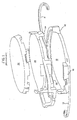
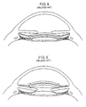
- the inventor of this application developed a multi-component intraocular lens, hereinafter referred to as the MC-IOL ( FIG. 1 ), for use following clear lens or refractive cataract surgery, wherein the optical properties of the MC-IOL can be modified at any post-operative time.
- the base intraocular lens component of the MC-IOL is shown in FIG. 1 .
- the mid lens attaches to the top of the base lens and holds the third component of the MC-IOL, the top lens, in place.
- the base intraocular lens 10 and the mid lens 20 each have securing flanges 16, 18 and 20, 24, respectively, extending therefrom.
- the MC-IOL also comprises at least one top lens 30, as illustrated in FIG. 1 .
- the top lens 30 is positioned on top of the mid lens 20. See FIGS. 1-2 .
- the MC-IOL also includes projections (or haptics) 11 and 13 which securely hold the MC-IOL in the tissue of the human eye.
- the above-described structure permits the base intraocular lens 10 to form a platform upon which the mid lens 20 is placed, and to hold the top lens 30.
- the MC-IOL replaces the crystalline lens of the human eye. Once a patient's eye has healed after such a surgery, the surgeon reenters the eye and replaces, if necessary, and more than once, the top lens 30 and the mid lens 20 to modify the optical characteristics of the eye until the desired levels for each optical characteristic are attained.
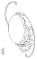
- FIGS. 3A-3B illustrate an assembled compound intraocular lens, hereinafter C-IOL, used with a preexisting lens within the human eye.
- the C-IOL has two components similar to the mid lens ( FIGS. 4A-4B ) and the top lens ( FIGS. 5A-5B ) components of the MC-IOL.
- FIG. 5A also illustrates the axis orientation mark 85 used in some embodiments of MC-IOL lenses to aid in positioning and orienting the lens.
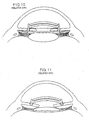
- the preexisting lens can be the crystalline lens of the eye with the C-IOL placed in the sulcus ( FIG. 6 ) or in the anterior chamber angle ( FIG. 7 ) of the eye's optical system.
- the C-IOL can also be used with a conventional IOL, as well as with an accommodating IOL, and mounted in the sulcus ( FIG. 8 ), in the anterior chamber angle ( FIG. 9 ), in the anterior chamber with posterior chamber fixation ( FIG. 10 ) or in the anterior chamber with iris fixation ( FIG. 11 ).
- a surgeon modifies the optical characteristics of the optical system of the eye by using the mid and top lenses in tandem with the preexisting conventional IOL implant or crystalline lens of the eye.
- the C-IOL and MC-IOL provide numerous enhanced features.
- the C-IOL and MC-IOL can each be structured as a monofocal or multifocal optical system, correct astigmatism, as well as comprise ultraviolet light-absorbing, tinted, or other such chemically treated materials.
- an adjustable MC-IOL or C-IOL is more desirable than a single component implant.
- MC-IOL multiple components
- an inventory of about one hundred components would be necessary.
- anterior chamber lenses progressive encapsulation or engulfment of the lens haptics by uveal tissue in the angle often occurs 1-2 years post-operatively. The engulfment typically makes the removal of the lenses and their haptics more difficult.
- Exchange of iris fixated anterior chamber lenses does not typically guarantee precise position or orientation. Posterior chamber lenses similarly cannot be removed because of posterior capsule fibrosis. Easy removal and exchangeability is critical for any customized emmetropic system, which can be provided by a specially designed multicomponent lens system.
- a MC-IOL having three elements rather than one permits refractive customization and adjustability for all refractive errors, as well as for all patients, while using a minimal number of lens elements or parts and requiring little customization on the part of the manufacturer.
- U.S. Pat. No. 5,288,293 to O'Donnell, Jr. discloses a method of modifying a single IOL.
- O'Donnell suggests that the refractive power of a single IOL may be varied before implantation so that the changes can be made in situ by the ophthalmologist after determining the extent of correction required to improve the vision of the patient before the lens is made.
- the surgical implantation procedure itself may create additional optical aberrations which cannot be anticipated preoperatively and thus the primary lens implant cannot account for these optical aberrations.
- a single component intraocular lens which in general is not designed to be removed and with only two optical surfaces, cannot accurately allow for compensation of sphere, cylinder, cylindrical axis, and all forms of optical aberrations that may be discovered after the initial implantation.
- the MC-IOL typically will have four removable optical surfaces which can compensate for these optical properties.
- the inventor of this application invented the previously discussed MC-IOL and C-IOL that are designed specifically to permit the easy exchange of optical elements at a post-operative period without risk to the human eye or to the patient, beyond the risk of ordinary intraocular surgery.
- the easy exchangeability of optical elements is critical because the actual surgery of implanting the lens in the first place, as well as variances in the manner in which the eye heals after implantation, potentially create distortions which may not stabilize for several months after the operation. Therefore, the ability to measure and to compensate for the distortion(s) optimally takes place several months after surgery and cannot typically be predicted prior thereto. Since the same surgical wound is used for both the primary and secondary operations, additional distortion due to wound healing would not be anticipated as a result of the second operation.
- the ability to exchange optical elements of a multicomponent or compound intraocular lens can be economical compared to removing, modifying, and re-implanting a single component lens, as well as easier to perform.
- the MC-IOL has four surfaces available for modification, two piano and two convex.
- the modification is made only to the piano surfaces to avoid interfering with the convex side which may already be used for correction of astigmatism (cylinder) or used as a multifocal lens surface.
- cylinder astigmatism
- multifocal lens surface The same preference applies to the CIOL, which has two surfaces available for modification, one piano and the other convex.
- the inventor of this application also developed a system for correcting optical aberrations in the MC-IOL, as described, for example, in U.S. Pat. No. 6,413,276 , for conducting measurements to determine any residual or new aberrations present in an operated eye after the biological healing parameters have stabilized, as well as to correct any errors in sphere, cylinder, or cylindrical axis, and for modifying one, two, or more existing lens elements within the implanted optical system based on the conducted measurements.
- the surgical procedure required to implant the intraocular lens components requires a high level of surgeon skill.
- implantation of the removable component of the lens requires the surgeon to directly visualize the placement of the lens in order to match the notches with the flanges.
- removal of the removable lens component requires a special forceps tool for grabbing the base lens, and releasing the tabs holding the sandwich and cap lens together with the base lens (see, for example, the system described in U.S. Pat. No. 5,968,094 ).
- intraocular lens systems used a rigid one piece poly methyl methacrylate (PMMA) lens.
- PMMA poly methyl methacrylate
- the PMMA lens is approximately six millimeters in diameter. Because the PMMA lens is rigid, insertion of the PMMA intraocular lens generally requires a seven or eight millimeter incision to be inserted into the eye. In contrast, a flexible or foldable lens can be manipulated and compacted to a much smaller size. Once compacted, the multi-component intraocular lens can be delivered using a relatively smaller incision, for example, about three millimeters or less. By using a smaller incision, the patient reaps optical and practical benefits.
- any time incisions are made to the cornea the cornea loses some of its natural globularity due to imperfections caused by the incisions and the resultant trauma.
- the imperfections in the cornea lead to induced astigmatism, or optical aberrations caused by irregularities in the shape of the cornea.
- a surgeon may also minimize the amount of induced astigmatism. Even though the three-component design simplifies the process of correcting induced astigmatism, minimizing the amount of induced astigmatism remains a primary goal for all intraocular surgeries.
- FIGS. 12-16 illustrate the invention disclosed in the '875 patent application.
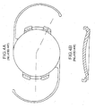
- FIG. 12A shows a top or plan view of an intraocular foldable base lens 100, which is similar to the MC-IOL base lens illustrated in FIG. 3 .
- the base lens 100 attaches to the eye by at least one haptic 120 and while the base lens 100 in FIG. 12A can be secured to the eye by at least one haptic, it is preferable that at least two haptics 120 be used.
- each haptic 120 extends outward from the base lens 100, and is tilted from between 10 to 20 degrees, in either direction, relative to a plane taken across the base lens, preferably having a 15 degree positive tilt.
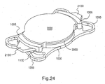
- the base lens 100 can also include one or more flanges 105 (1005, FIG. 24 ) disposed on and extending outwardly away from the body of the base lens 100 (1000, FIG. 24 ).
- Each flange 105 (1005, FIG. 24 ) can also have a slot 110 (1100, FIG. 24 ) designed or configured to receive or accept an assembly of a top lens 300 (3000, FIG. 24 ) and a mid lens 200 (2000, FIG. 24 ) therein.
- Each flange 105 (1005, FIG. 24 ) and slot 110 (1100, FIG. 24 ) is an essential feature to the design of base lens 100 (1000, FIG. 24 ).
- the MC-IOL concept allows for adjustments or enhancement operations, beyond its use in primary cataract, clear lens, surgery to compensate for any miscalculation or any biological variability or any change in the condition of the eye over time after the primary operation.
- the surgeon must have easy access to the front lens assembly 200, 300 (2000, 3000 FIG. 24 ).
- the front lens assembly 200, 300 (2000, 3000 FIG. 24 ) must be left out of the capsule, in the sulcus.
- the base lens 100 (1000, FIG. 24 ) is left in the capsule.
- FIG. 14A (2100, FIG.
- the vertically extending flanges 105 (1005, FIG. 24 ) and their corresponding slots 110 (1100, FIG. 24 ) allow a space between the haptics 210, see FIG. 14A (2100, FIG. 24 ) of the front lens assembly 200, 300 (2000, 3000 FIG. 24 ) and the base lens 100 (1000, FIG. 24 ) so that a special instrument, referred to as a capsule snare, allows the surgeon to place the front lens assembly haptic 210 (2100, FIG.
- the flanges 105 (1005, FIG. 24 ) and slots 110 (1100, FIG. 24 ) are necessary features of the MC-IOL design to assure easy removal and replacement of the front lens assembly 200, 300 (2000, 3000, FIG. 24 ) during an enhancement operation.
- the edges and haptics 210 (2100, FIG. 24 ) are inaccessible to the surgeon due to capsule contracture around the edges and haptics 120 (1200, FIG. 24 ) of the base lens 100 (1000, FIG. 24 ), that is, the normal healing process.
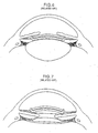
- the base lens in FIG. 13 is similar to the base lens 100 ( FIGS. 12A-12B ), except for a groove 130 being defined therein that extends along the entire outer periphery, and a plurality of attachment points 140, which serve to attach the optical region 150 to the base lens.
- the foldable MC-IOL disclosed in the inventor's '875 application includes two or more additional refractive components, i.e., a top lens 300 and a mid lens 200.
- the mid lens 200 which typically allows spherical adjustments, is illustrated in FIGS. 14A-14B , while the top lens 300 ( FIG. 15 ) carries the astigmatic correction and has an orientation projection 305.
- the mid lens 200 may include at least one projection 210 extending away from the body of the mid lens 200 and may have varying lengths depending on the shape and number of projections.
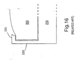
- the mid lens 200 also includes a side portion 250 which extends upward, and terminates at a lip 225, as illustrated in FIG. 14B .
- the side portion 250 and lip 225 extend along the outer circumference of the mid lens 200, thereby defining a notch 230.
- the top lens 300 Prior to insertion into the eye, the top lens 300 engages the notch 225 of the mid lens, such that a seal is formed between the notch 225 and the top lens 300, and which holds the mid lens 200 and the top lens 300 together as a single assembly ( FIG. 16 ).
- the top lens 300 is oriented so that, when the top lens 300 is inserted into the mid lens 200, raised projections or notches 305 of the top lens 300 face the mid lens 200 or may also project away from the mid lens 200.
- the notches or projections 305 can provide directional and axial orientation for the top lens, similar to the axis orientation marks 85 of FIG. 5 .
- the lens manufacturer assembles the mid lens 200 and the top lens 300 to a predetermined axis orientation to correct the astigmatism, and then the surgeon, outside the eye assembles the front lens assembly 200, 300, and the base lens 100 and inserts the completed assembly into the eye as one folded piece such that the mid lens 200 is sandwiched between the base lens 100 and top lens 300.
- the surgeon inserts the top lens 300 and the mid lens 200 assembly into the eye and then attaches the assembly to the base lens 100 by sliding a projection 210 of the mid lens 200 into a slot 110 of a corresponding flange 105' of the base lens 100, the latter two step assembly allows for a smaller surgical incision.
- the surgeon adjusts the mid lens 200 and the top lens 300 until the other projection(s) 210 line up with the other slot(s) 105. Once all projections 210 have been inserted into their corresponding slots 110, the assembly of the top lens 300 and the mid lens 200 is secured in the base lens 100, and the procedure is completed.
- the surgeon may perform a disassembly procedure as discussed herein.
- a cannula containing visco elastic material would be introduced into the eye and positioned at the interface between the lens assembly (mid lens 200 and top lens 300) and the base lens 100.
- the injection of visco elastic causes the mid 200/top 300 lens assembly to elevate, thus disengaging the projections 210 from the slots 110 in the base lens 10.0.
- the original lens assembly would then be removed from the eye, and a new lens assembly placed into the eye and attached to the base lens 100 similar to as described above in the primary operation.
- the inventor's application Ser. No. 12/000,364 published as US-A-2008/0215147 taught a different orientation of the mid lens and top lens than the orientation disclosed in the inventor's '875 application.
- the '364 application inverted or reversed the order of the mid lens and top lens such that the top lens is placed on top of the base lens and the mid lens then positioned on top of the top lens such that the three components are oriented in an order where the base lens is most posterior relative to the patient's eye.
- the top lens is then placed on the base lens and the mid lens arranged on the top lens such that the mid lens is most anterior relative to the patient's eye and the top lens is arranged between or in the middle of the base and mid lens.
- the inventor's 875 application teaches the mid lens includes a notch with which a projection of the top lens engages to securely maintain the mid/top lens assembly
- the inventor's '364 application joins the top and mid lenses to each other using a joining means, such as, for example, a medical adhesive that is applied in at least one location where the mid lens interfaces with the top lens.
- the inventor's '364 application teaches a feature wherein the haptic of the mid lens has projections extending anteriorly and posteriorly that capture the top lens (circular configuration) and retain the top and mid lens (circular configuration) as an optical assembly.
- FIGS. 17A-21 the inventor's '364 application discloses a medical adhesive MA is used to join the mid lens 200' and top lens 300', respectively, together as a single, integrated unit or assembly.
- FIGS. 17B and 18 illustrate how the medical adhesive MA is applied to the inner surface 250a of a side portion 250' of themid lens 200' and/or an outer peripheral surface 350a of the top lens 300' to securely retain the mid lens 200' and top lens 300' together.
- FIGS. 17B and 18 illustrate how the medical adhesive MA is applied to the inner surface 250a of a side portion 250' of themid lens 200' and/or an outer peripheral surface 350a of the top lens 300' to securely retain the mid lens 200' and top lens 300' together.
- the inventor's '364 application teaches that the medical adhesive MA can also be applied along an upper surface of the mid lens 200" and/or an entire lower surface of the top lens 300", either entirely or in select, discrete locations thereon, which directly opposes the upper surface of the mid lens 200" to join the top and mid lenses 300" and 200" into a single unit or assembly.
- An embodiment of the present invention includes a multi-component intraocular lens, wherein the base lens is attached with haptics, and the top and mid lenses are assembled outside the eye.
- an embodiment of the present invention includes manufacturing the mid lens and the top lens from a material having adhesive properties such that the mid lens and the top lens naturally adhere to each other.
- the material from which the top and mid lenses are manufactured can be, but is in no way limited to, a hydrophilic acrylic that has a self-adhesive property such that the top and mid lenses adhere together without the need for a medical adhesive or any other joining means being administered to either of the lenses.
- the present invention includes a feature wherein the top lens and the mid lens are manufactured from the same material. It is also within the scope of the present invention for the top lens and the mid lens to be manufactured from different materials. Additionally, the base lens may be made from the same material as either one of or both of the top lens and the mid lens, or the base lens may be made from a material that is different from the material from which the top lens and the mid lens are manufactured. For example, while an optical assembly defined by the top lens and the mid lens joined together may be made of a hydrophilic material, the base lens may be made form a non-hydrophilic material.
- the optical assembly defined by the top and mid lenses is an aspect of the present invention to negate the self-adhesive property of the top and mid lenses by treating at least the non-optical aspects of at least one, and preferably both, of the top lens and the mid lens so the optical assembly does not stick or adhere to the base lens.
- Such treatment may include, but is in no way limited to, frosting the non-optical aspects of the optical assembly, e.g., the surface of the flange contacting the base lens, with a non-adhesive substance, or providing the portions of the optical assembly and/or the base lens that contact each other with a surface treatment wherein the surface is modified such that the optical assembly and base lens will not adhere to each other, e.g., knurled surfaces, and the like.
- the present invention includes a feature wherein the optical assembly is expanded to include additional lenses than the mid lens and top leans.
- An aspect of the present invention is to stack a plurality of lenses that make up the optical assembly, and insert the optical assembly into the base lens.
- the stacked optical assembly would include a plurality of lenses, each lens addressing different optical elements. For example, if the mid lens is a spherical lens and the top lens is a toric lens, another lens of the optical assembly could address or correct chromophore or color related issues, yet another lens could address astigmatisms, another lens could address nearsightedness or farsightedness, while another lens could address higher order optical aberrations or spherical aberrations or both.
- the additional lenses could also be stacked on either side of the mid lens, that is, either between the mid lens and the top lens, or between the mid lens and the base lens, or even on top of the top lens such that the top lens is between the mid lens and any additional lenses.
- the intraocular lens system of the present invention allows assembly without the use of special equipment or techniques for securing the top and mid lenses together.
- the fully assembled or end appearance of the base lens 1000 of the present invention is substantially similar to the base lens 100 and 100" described above. Therefore, a detailed description of many of the common features of the base lens 1000 relative to the base lens 100 and 100" is omitted herefrom in order to avoid redundancy.
- the foldable MC-IOL according to the present invention also includes one or more additional refractive components, including an assembly of a mid lens 2000 and a top lens 3000, described more fully herein.
- additional refractive components including an assembly of a mid lens 2000 and a top lens 3000, described more fully herein.
- the top lens 300 and the mid lens 200 of the '875 application, as well as the mid lens 200' and top lens 300' of the '364 application are similar to the mid lens 2000 and top lens 3000 described below, with the exception of certain distinguishing aspects.
- a certain distinguishing aspect of the present invention relative to the disclosure of the '875 and '364 applications is the material from which the top lens 3000 and the mid lens 2000 are manufactured.
- the mid lens 2000 and top lens 3000 are manufactured from a preferably foldable material, e.g., hydrophilic acrylic, hydrophobic acrylic, silicone and the like, such that the mid and top lenses 2000 and 3000 inherently or naturally adhere or stick to each other such that the adhesive MA of the '364 application is not necessary, as is seen with hydrophilic acrylics. That is, as shown in FIG.
- the top lens 3000 and mid lens 2000 adhere to each other without any of the adhesive MA from the '364 application disposed between opposing faces of the lenses 2000 and 3000, or between an outer peripheral surface 3500a of the top lens 3000 and an inner peripheral surface 2500a of a side portion 2500 of the mid lens 2000, as shown in FIG. 23 .
- top lens 3000 and mid lens 2000 are preferably manufactured from a hydrophilic material, it may not be necessary for the lenses 2000 and 3000 to be manufactured from the same hydrophilic material.
- the lenses 2000 and 3000 are manufactured from a hydrophilic acrylic material, a hydrophobic acrylic or any other suitable material, it may be that the natural physical and/or chemical properties of the material is such that the properties hold the lenses 2000 and 3000 together wherever the lenses 2000 and 3000 contact each other. Accordingly, the lenses 2000 and 3000 are very difficult to separate from each other.
- the adhesive MA from the '364 application is omitted from the present invention, wherein assembly of the optical assembly including the top lens 3000 and mid lens 2000 is simplified, faster, needs less materials, and reduces the overall costs.
- the optical assembly i.e., the top lens 3000 and mid lens 2000
- the optical assembly is first assembled by the lenses 2000 and 3000 being adhered together by the manufacturer.
- at least one, and preferably two, projections 2100 of the mid lens 2000 portion of the optical assembly are passed through a corresponding slot 1100 defined in a corresponding flange 1005 of the base lens 1000 and overlaps a portion of the corresponding haptic 1200 of the base lens 1000.
- the optical assembly i.e., top lens 3000 and mid lens 2000
- the optical assembly is exchangeable with another optical assembly in order to adapt or adjust the optical properties of the patient's vision
- the optical assembly not be capable of adhering to any portion of the base lens 1000.
- the non-optical portions of the optical assembly which includes portions of the optical assembly that physically contact or overlap with the base lens 1000, should be treated so as not to have any adhesive characteristics. That is, the non-optical portions of the optical assembly cannot adhere or otherwise stick to the base lens 1000 such that the optical assembly is prevented from being removed from the base lens 1000.
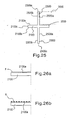
- FIG. 25 is a schematic diagram of a portion of the mid lens 2000 which engages the top lens 3000 and also passes through or otherwise contacts the base lens 1000.
- the top lens 3000 is illustrated in dashed lines as abutting against the inner surface 2500a of an upper side portion 2500 of the mid lens 2000. That is, the top lens 3000 is shown, for exemplary purposes, as being placed on a top or upper surface thereof, however, it is also within the scope of the present invention for the top lens 3000 to be positioned on a lower surface of the mid lens 2000 so as to be abutting against the inner surface 2500a of a lower side portion 2500 thereof.
- portions of the base lens 1000 to contact an outer surface 2500b of the side portion 2500, an upper surface 2500c of the side portion 2500, an upper surface 2100a of the projection 2100, a lower surface 2100b of the projection, and an outer surface 2100c of the projection 2100.
- the possible contact surfaces 2500b, 2500c, 2100a, 2100b, and 2100c are subjected to a treatment that prevents such surfaces from being able to adhere to a corresponding portion of the base lens 1000 contacted by the surfaces.
- At least one of the surfaces 2500b, 2500c, 2100a, 2100b, and 2100c can be frosted or otherwise chemically treated, or physically worked so as not to have any adhesive properties.
- the upper surface 2100a of the projection 2100 is frosted F with a suitable chemical or substance that prevents the mid lens 2000 from being able to adhere to the base lens 1000.
- the upper surface 2100a of the projection 2100 is roughened or knurled to have a knurled surface K.
- the treated surface can be any one of or any combination of the various surfaces 2500b, 2500c, 2100a, 2100b, and 2100c and how the surface or surfaces 2500b, 2500c, 2100a, 2100b, and 2100c are treated can vary. Furthermore, although a knurled surface K is shown in FIG.
- the relevant surface 2500b, 2500c, 2100a, 2100b, and 2100c to be treated in any suitable manner, such as, but in no way intended to limit possible alternatives, shot peening, or coated with a non-adhesive polymer, and the like.
- the mid lens 2000 and base lens 1000 may be made from different materials or at least materials that are not adhesive relative to each other.
- portions of the mid lens 2000 or other portions of the top lens 3000 that physically contact any portion of the base lens 1000 are also contemplated as being treated so as not to have any properties of portions that are able to adhere to the base lens 1000.
- the surfaces that can be treated are not limited to the outer portions of the optical assembly, but may also include the outermost planar surface of either lens 2000 or 3000, depending on whichever lens is contacting a corresponding planar surface of the base lens 1000.
- the possible contact surfaces 2500b, 2500c, 2100a, 2100b, and 2100c to a treatment that prevents such surfaces from being able to adhere to a corresponding portion of the base lens 1000 contacted by the surfaces, exchanging an existing optical assembly with a new optical assembly can be accomplishes easily and quickly, and without damaging aspects of the base lens 1000.
- FIGS. 27A-D illustrate another aspect of the present invention.
- the optical assembly was described as having two optical elements, that is, the top lens 3000 and the mid lens 2000, adhered together.
- the top lens 3000 would be a toric lens (cylindrical, non-spherical) and the mid lens 2000 would be a non-toric lens (spherical, multi-focal).
- the optical assembly may include additional optical elements wherein the top lens 3000, mid lens 2000, and any additional lens 4000 would be provided in a stacked arrangement within the optical assembly. It should be noted that although FIGS.
- FIG. 27A-C illustrate three optical elements (i.e., lenses 2000, 3000 and 4000), it is within the scope of the invention for additional lenses to be included such that there are four, five, six, ... twelve lenses provided in a stacked arrangement within the optical assembly. However, four lenses are discussed herein to simplify the understanding thereof.
- the additional lens 4000 which in the illustrated example is provided between the mid lens 2000 and base lens 1000, may add chromophores or address different types of optical aberration.
- the lenses 2000, 3000, and 4000 are manufactured from a material having the adhesive properties such that the lenses 2000, 3000 and 4000 are inherently held together by their natural physical and/or chemical properties.
- the lenses 2000, 3000 and 4000 can further be held together by a flange 225 extending radially inward from an upper end of the side portion 2500. See FIG. 16 for an example of the flange 225.
- the top lens 3000 and mid lens 2000 may be switched such that the additional lens 4000 is provided between the base lens 1000 and the top lens 3000.
- the additional lens 4000 can be positioned furthest from the base lens 1000, as shown in FIG. 27C .
- the order in which the lenses are arranged in the optical assembly can be changed to suit the desired optical properties to be obtained by the optical assembly.
- the type of optical correction provided by each lens e.g., spherical, toric, chromophore, astigmatism, night vision, and the like, of the optical assembly may vary depending on the optical properties needed by the patient.
- the mid lens 2000 is positioned between the base lens 1000 and the top lens 3000 as described above.
- the additional lens 4000 can be a lens that corrects or addresses a spherical aberration and is positioned between the mid lens 2000 and the base lens 1000, wherein yet other lenses 5000, 6000, 7000 and 8000 are positioned between the mid lens 2000 and the base lens 1000, and wherein the lens 5000 can correct or address higher order aberrations, lens 6000 can be a multi-focal lens, lens 7000 can be an aspheric lens, and lens 8000 can be a chromofore lens.
- the types of optical conditions that the additional lenses 4000 through 7000 correct or address, as well as their location or arrangement within the optical assembly, described above is merely exemplary and it is intended that the optical conditions corrected or addressed by each lens, and the location of each lens within the optical assembly may vary as needed to provide the desired optical properties.
- the mid lens 2000 it is within the scope of the invention for the mid lens 2000 to be provided between the base lens 1000 and the top lens 3000, wherein some of the lenses 4000, 5000 and 6000 can be provided between the base lens 1000 and the mid lens 2000, while the other lens 7000 or lenses can be provided between the mid lens 2000 and the top lens 3000.
- the location of the mid lens 2000 and top lens 3000 can be switched and the location of the other lenses 4000, 5000, 6000, and 7000, for example, can also be rearranged based on the needed optical properties to be provided by the optical assembly.
- any one of the reference numbers e.g., 4000, 5000, 6000 and 7000, could represent or illustrate a space or gap between neighboring lenses.
- reference number 6000 would not be a lens, but instead defines a space or gap between lenses 5000 and 7000.
- reference numbers 5000 and 7000 could define a space or a gap between base lens 1000 and lens 6000, and lens 6000 and lens 4000.
- a chamber to be defined between neighboring lenses, wherein the chamber would hold or contain a liquid, or semi-solid, or a gelatinous material having pharmalogical and/or optical properties.
- the base lens 1000 prefferably be a spherical lens or an aspherical lens, depending on the desired optical properties to be provided by the inventive optical assembly to the patient.
- the mid lens 2000 and top lens 3000 have, until now, been described as separate and distinct components of the optical assembly.
- a bottom surface of the lens 8000 that is, the half of the lens 8000b closest to the base lens 1000, can be or define a non-toric surface, while a top surface of the lens 8000a furthest from the base lens 1000, can be or define a toric surface.
- the optical properties of the sections of the lens 8000a and 8000b can be formed by lathing or molding the surfaces to produce the toric, non-toric, multifocal, etc. optical properties.
- the surgeon further customizes the lens 8000 by it's surgical orientation in the eye, which is determined by the surgeon at the time of the primary surgery.
- the surgeon can use a fully customized front lens assembly 2000, 3000, 4000, 5000, 6000, 7000, where the orientation is set by the manufacturer as specified by the surgeon (fully customized manufacturing).
- the surgical orientation would always be the same.
- the optical assembly having the base lens, mid lens and top lens for example, to be preassembled by the surgeon prior to the surgical procedure.
- the entire optical assembly can then be injected into the eye of the patient, rather than individual components being inserted one at a time by the surgeon.
- the top lens of the intraocular lens system rotates.
- a fluorescent dye or some other material or chemical that is not visible in natural light by the human eye it is also within the scope of the present invention for a fluorescent dye or some other material or chemical that is not visible in natural light by the human eye to be incorporated into the top lens by the manufacturer prior to surgical use and function as an orientation mark, much like the mark 85 illustrated in FIG. 5A .
- the location of the mark 85 may vary from a mark on the outer peripheral edge of the top lens to a line spanning across the entire or partial central portion of the lens.
- the front lens assembly (mid lens 2000, top lens 3000, etc.) would be removed and exchanged with a new custom front lens assembly provided by the manufacturer according to the surgeon's post operative measurements.
- the orientation of the base lens and therefore the front lens assembly as well is fixed by virtue of the capsule contracture around the haptics. Therefore, in any secondary enhancement operation, any orientation and/or axis configuration must be customized by the manufacturer according to the surgeon's postoperative measurements. This is in contrast to the primary surgery where either the surgeon does have the ability to determine orientation as an alternative option to the manufacturer doing this in a fully customized front lens.
- the exchange of the front lens assembly can occur at any time in the patient's life after the primary surgery and for any reason, i.e., unintended postoperative rotation of the lens, dissatisfaction on the part of the patient because of optic distortion seen with some multifocal optics, changes of medical condition of the eye, e.g., SMD, etc.
- the present invention may provide a relatively simple, easy to manufacture and insert intraocular lens implant that provides the patient with a customized optical assembly configured to address the particular needs of the patient's vision.
Landscapes
- Health & Medical Sciences (AREA)
- Ophthalmology & Optometry (AREA)
- Cardiology (AREA)
- Oral & Maxillofacial Surgery (AREA)
- Transplantation (AREA)
- Engineering & Computer Science (AREA)
- Biomedical Technology (AREA)
- Heart & Thoracic Surgery (AREA)
- Vascular Medicine (AREA)
- Life Sciences & Earth Sciences (AREA)
- Animal Behavior & Ethology (AREA)
- General Health & Medical Sciences (AREA)
- Public Health (AREA)
- Veterinary Medicine (AREA)
- Prostheses (AREA)
Claims (24)
- Ein Verfahren zur Herstellung einer mehrteiligen, in ein optisches System eines menschlichen Auges in einer Primäroperation implantierbaren Intraokularlinse, wobei das Verfahren umfasst:Herstellung einer Basislinse (1000) mit einer vorderen Oberfläche, die einer Vorderseite des menschlichen Auges zugewandt ist, mit einer hinteren Oberfläche auf der relativ zur vorderen Oberfläche gegenüberliegenden Seite der Basislinse (1000) und die einer Rückseite des menschlichen Auges zugewandt ist, eine umlaufende Seitenoberfläche, die die vordere und hintere Oberfläche verbindet, die hergestellt ist aus einem basisfaltbaren Material, wobei die Basislinse (1000) zumindest eine Kerbe umfasst, die in der umlaufenden Seitenoberfläche der Basislinse (1000) definiert ist, und einen Kragen (1005) ausgestaltet, um in die Kerbe einzugreifen; und Herstellung einer optischen Frontlinsenanordnung umfassend eine erste Linse und eine zweite Linse, wobei die erste und zweite Linse hergestellt sind aus ersten beziehungsweise zweiten faltbaren Materialien,wobei der Kragen (1005) angeordnet ist auf und rechtwinklig von der vorderen Oberfläche der Basislinse (1000) in Richtung der Vorderseite des menschlichen Auges ragt, wobei der Kragen eine in diesem definierte Ausnehmung (1100)umfasst, durch welche die Basislinse (1000) wahlweise in die optische Frontlinsenanordnung eingreift, wobei die Ausnehmung nur oberhalb der vorderen Oberfläche der Basislinse (1000) angeordnet ist,wobei die erste Linse eine Mittellinse und die zweite Linse eine Oberlinse ist, wobei die Mittellinse zumindest einen Vorsprung (2100) aufweist, der sich von einer äußeren umlaufenden Oberfläche der Mittellinse wegerstreckt und welcher ausgestaltet ist, um in die im Kragen der Basislinse definierte Ausnehmung (1100) einzugreifen,wobei die optische Frontlinsenanordnung eine Achsenorientierung hat, um den Astigmatismus zu korrigieren,dadurch gekennzeichnet, dass die erste Linse direkt an der zweiten Linse frei von irgend einem Material oder irgend einer Substanz dazwischen angehaftet wird, und dass die Achsenorientierung der optischen Fronlinsenanordnung systematisch in der gleichen Weise ohne Anpassung hergestellt wird, um dem Operateur die chirurgische Anpassung der optischen Frontlinsenanordnung im Auge zum Zeitpunkt der Primäroperation zu ermöglichen.
- Das Verfahren zur Herstellung nach Anspruch 1, wobei das erste und zweite faltbare Material ein hydrophiles Material und das Basismaterial ein nicht hydrophiles Material ist.
- Das Verfahren zur Herstellung nach Anspruch 1., wobei entweder die Mittellinse zwischen der Oberlinse und der Basislinse angeordnet ist oder die Oberlinse zwischen der Mittellinse und der Basislinse angeordnet ist.
- Das Verfahren zur Herstellung nach Anspruch 1, wobei eine freiliegende Oberfläche von zumindest einem des zumindest einem Vorsprungs und der äußeren umlaufenden Oberfläche der Mittellinse eine nicht adhäsive Fläche umfasst.
- Das Verfahren zur Herstellung nach Anspruch 4, wobei die nicht adhäsive Fläche eine mattiert, eine nicht adhäsive polymer Beschichtung, gerändelt oder gestrahlt ist.
- Das Verfahren zur Herstellung nach Anspruch 1, wobei die optische Anordnung weiterhin zumindest eine zusätzliche Linse, hergestellt aus einem zusätzlichen faltbaren Material, aufweist.
- Das Verfahren zur Herstellung nach Anspruch 6, wobei die zumindest eine zusätzliche Linse zwischen der ersten Linse und der Basislinse angeordnet ist und nur an der ersten Linse haftet.
- Verfahren zur Herstellung nach Anspruch 7, wobei die zumindest eine zusätzliche Linse eine dritte Linse und eine vierte Linse aufweist.
- Das Verfahren nach Anspruch 6, wobei die zweite Linse zwischen der ersten Linse und der Basislinse angeordnet ist, und die zumindest eine zusätzliche Linse zwischen der zweiten Linse und der Basislinse angeordnet ist und nur an der zweiten Linse anhaftet.
- Das Verfahren nach Anspruch 9, wobei die zumindest eine zusätzliche Linse eine dritte Linse und eine vierte Linse aufweist, die dritte Linse an der vierten Linse und der zweiten Linse anhaftet.
- Das Verfahren zur Herstellung nach Anspruch 6, wobei die zumindest eine zusätzliche Linse zwischen den ersten und den zweiten Linsen angeordnet ist und an beiden der ersten und der zweiten Linsen haftet.
- Das Verfahren zur Herstellung nach Anspruch 11, wobei die zumindest eine zusätzliche Linse eine dritte und eine vierte Linse aufweist.
- Das Verfahren zur Herstellung nach Anspruch 6, wobei die zumindest eine zusätzliche Linse auf einer vorderen Oberfläche einer von beiden der ersten und zweiten Linsen angeordnet ist, wobei die erste und zweite Linse zwischen der zumindest einen zusätzlichen Linse und der Basislinse angeordnet sind, und die zumindest eine zusätzliche Linse an derjenigen von der ersten und zweiten Linse anhaftet, die am weitesten entfernt von der Basislinse ist.
- Das Verfahren zur Herstellung nach Anspruch 11, wobei die zumindest eine zusätzliche Linse eine dritte Linse und eine vierte Linse aufweist.
- Das Verfahren zur Herstellung nach Anspruch 11, wobei die zumindest eine zusätzliche Linse eine dritte Linse und eine vierte Linse aufweist, die dritte Linse zwischen der ersten Linse und der Basislinse angeordnet ist und nur an der ersten Linse anhaftet, und die vierte Linse zwischen der ersten Linse und der zweiten Linse angeordnet ist und an beiden der ersten und der zweiten Linse anhaftet.
- Das Verfahren zur Herstellung nach Anspruch 6, wobei die erste Linse, die zweite Linse und die zumindest eine zusätzliche Linse jeweils unterschiedliche optische Eigenschaften jeweils zueinander aufweisen.
- Das Verfahren zur Herstellung nach Anspruch 14, wobei die unterschiedlichen optischen Eigenschaften aus einer Gruppe umfassend torisch, nicht torisch, sphärische Aberrationen, Aberrationen höherer Ordnung, multifokal, asphärisch und Chromophor ausgewählt sind.
- Das Verfahren zur Herstellung nach Anspruch 1, wobei der zumindest eine Vorsprung zwei Vorsprünge aufweist, ein erster Vorsprung sich in eine erste Richtung erstreckt und ein zweiter Vorsprung sich in eine zweite Richtung erstreckt, die sich von ersten Richtung unterscheidet.
- Das Verfahren zur Herstellung nach Anspruch 18, wobei eine Kontaktfläche der optischen Anordnung, welche die hintere Oberfläche der Basislinse berührt, eine nicht adhäsive Fläche aufweist.
- Das Verfahren zur Herstellung nach Anspruch 19, wobei die nicht adhäsive Fläche mattiert, eine nicht adhäsive polymere Beschichtung, gerändelt oder gestrahlt ist.
- Das Verfahren zur Herstellung nach Anspruch 1, wobei die Basislinse sphärisch oder asphärisch ist
- Das Verfahren zur Herstellung nach Anspruch 1, wobei eine Kammer zwischen einem von der ersten und der zweiten Linse der optischen Anordnung und der Basislinse definiert ist.
- Das Verfahren zur Herstellung nach Anspruch 6, wobei eine Kammer zwischen der ersten Linse und der zweiten Linse der optischen Anordnung und einer von der zumindest einen zusätzlichen Linse und der Basislinse definiert ist.
- Das Verfahren zur Herstellung nach Anspruch 1, wobei die Intraokularlinse gestaltet ist, um in menschlichem Auge zu rotieren.
Applications Claiming Priority (2)
| Application Number | Priority Date | Filing Date | Title |
|---|---|---|---|
| US12/499,613 US8066769B2 (en) | 2007-01-29 | 2009-07-08 | Intraocular lens system |
| PCT/US2010/041429 WO2011006008A1 (en) | 2009-07-08 | 2010-07-08 | Intraocular lens system |
Publications (3)
| Publication Number | Publication Date |
|---|---|
| EP2451380A1 EP2451380A1 (de) | 2012-05-16 |
| EP2451380A4 EP2451380A4 (de) | 2012-12-12 |
| EP2451380B1 true EP2451380B1 (de) | 2014-03-05 |
Family
ID=43429550
Family Applications (1)
| Application Number | Title | Priority Date | Filing Date |
|---|---|---|---|
| EP10797875.1A Active EP2451380B1 (de) | 2009-07-08 | 2010-07-08 | Methode zur herstellung eines ntraokularen linsensystem |
Country Status (7)
| Country | Link |
|---|---|
| US (1) | US8066769B2 (de) |
| EP (1) | EP2451380B1 (de) |
| JP (2) | JP5302461B2 (de) |
| CN (1) | CN102647959A (de) |
| CA (1) | CA2767431C (de) |
| ES (1) | ES2465567T3 (de) |
| WO (1) | WO2011006008A1 (de) |
Families Citing this family (36)
| Publication number | Priority date | Publication date | Assignee | Title |
|---|---|---|---|---|
| US9398949B2 (en) * | 2007-01-29 | 2016-07-26 | Emmetropia, Inc. | Intraocular lens system |
| US9220590B2 (en) | 2010-06-10 | 2015-12-29 | Z Lens, Llc | Accommodative intraocular lens and method of improving accommodation |
| US20110313521A1 (en) * | 2010-06-21 | 2011-12-22 | Angelopoulos Robert D | Intraocular rings and associated systems and methods |
| US10080648B2 (en) | 2012-01-24 | 2018-09-25 | Clarvista Medical, Inc. | Modular intraocular lens designs, tools and methods |
| US10028824B2 (en) * | 2012-01-24 | 2018-07-24 | Clarvista Medical, Inc. | Modular intraocular lens designs, tools and methods |
| ES2890415T3 (es) | 2012-01-24 | 2022-01-19 | Univ Colorado Regents | Diseños y métodos de lente intraocular modular |
| US9364316B1 (en) | 2012-01-24 | 2016-06-14 | Clarvista Medical, Inc. | Modular intraocular lens designs, tools and methods |
| TWI588560B (zh) | 2012-04-05 | 2017-06-21 | 布萊恩荷登視覺協會 | 用於屈光不正之鏡片、裝置、方法及系統 |
| US9364318B2 (en) | 2012-05-10 | 2016-06-14 | Z Lens, Llc | Accommodative-disaccommodative intraocular lens |
| US9201250B2 (en) | 2012-10-17 | 2015-12-01 | Brien Holden Vision Institute | Lenses, devices, methods and systems for refractive error |
| JP2015533430A (ja) | 2012-10-17 | 2015-11-24 | ブリエン ホールデン ビジョン インスティテュートBrien Holden Vision Institute | 屈折異常用のレンズ、デバイス、方法、及びシステム |
| US9486311B2 (en) | 2013-02-14 | 2016-11-08 | Shifamed Holdings, Llc | Hydrophilic AIOL with bonding |
| US10195018B2 (en) | 2013-03-21 | 2019-02-05 | Shifamed Holdings, Llc | Accommodating intraocular lens |
| EP4257359A3 (de) | 2013-03-21 | 2023-12-06 | Shifamed Holdings, LLC | Akkommodative intraokularlinse |
| CN105744914B (zh) * | 2013-08-20 | 2017-08-04 | 欧酷兰德斯控股公司 | 眼内晶状体组件 |
| DE102013017948B4 (de) * | 2013-10-29 | 2018-10-11 | Carl Zeiss Meditec Ag | Flüssigkeiten und Gels für die Ophthalmologie und Mikroskopiesystem zur Beobachtung der selben |
| CN106413634B (zh) | 2013-11-01 | 2019-03-05 | 雷恩斯根公司 | 双部件调节性人工晶状体设备 |
| EP3107510B1 (de) | 2014-02-18 | 2023-04-19 | Alcon Inc. | Vorrichtung zum entfernen einer intraokularlinse |
| WO2015134058A1 (en) * | 2014-03-07 | 2015-09-11 | Mccafferty Sean | Refocusable lens system with mutually-applanating internal surfaces |
| US10004596B2 (en) | 2014-07-31 | 2018-06-26 | Lensgen, Inc. | Accommodating intraocular lens device |
| CA2959354C (en) | 2014-08-26 | 2018-08-21 | Shifamed Holdings, Llc | Accommodating intraocular lens |
| DE102014221373A1 (de) * | 2014-10-21 | 2016-04-21 | Implandata Ophthalmic Products Gmbh | Kombiniertes Augenimplantat |
| ES2651511T3 (es) | 2015-01-06 | 2018-01-26 | Infinitevision Optics | Lente intraocular de múltiples componentes |
| JP7002331B2 (ja) | 2015-01-30 | 2022-01-20 | クラービスタ メディカル,インコーポレイテッド | 眼内挿入用に構成された装置 |
| CN104720933A (zh) * | 2015-03-16 | 2015-06-24 | 北京艾克伦医疗科技有限公司 | 可替换式多组件多功能人工晶状体系统 |
| CN106264787B (zh) * | 2015-05-18 | 2021-07-06 | 爱博诺德(苏州)医疗器械有限公司 | 一种可固定人工晶状体的人工虹膜及其材料与加工方法 |
| JP6993328B2 (ja) | 2015-11-04 | 2022-01-13 | クラービスタ メディカル,インコーポレイテッド | モジュール式眼内レンズシステム |
| US11141263B2 (en) * | 2015-11-18 | 2021-10-12 | Shifamed Holdings, Llc | Multi-piece accommodating intraocular lens |
| CN108778185B (zh) | 2015-12-01 | 2021-04-27 | 雷恩斯根公司 | 调节性人工晶状体装置 |
| US11045309B2 (en) | 2016-05-05 | 2021-06-29 | The Regents Of The University Of Colorado | Intraocular lens designs for improved stability |
| EP3503843B1 (de) | 2016-08-24 | 2023-11-15 | Carl Zeiss Meditec AG | Akkommodative-disakkommodative dualmodus-intraokularlinse |
| US10350056B2 (en) | 2016-12-23 | 2019-07-16 | Shifamed Holdings, Llc | Multi-piece accommodating intraocular lenses and methods for making and using same |
| AU2018277037B2 (en) | 2017-05-30 | 2024-04-18 | Shifamed Holdings, Llc | Surface treatments for accommodating intraocular lenses and associated methods and devices |
| US11266496B2 (en) | 2017-06-07 | 2022-03-08 | Shifamed Holdings, Llc | Adjustable optical power intraocular lenses |
| US11382736B2 (en) | 2017-06-27 | 2022-07-12 | Alcon Inc. | Injector, intraocular lens system, and related methods |
| US11357620B1 (en) | 2021-09-10 | 2022-06-14 | California LASIK & Eye, Inc. | Exchangeable optics and therapeutics |
Family Cites Families (81)
| Publication number | Priority date | Publication date | Assignee | Title |
|---|---|---|---|---|
| US2036379A (en) * | 1932-06-06 | 1936-04-07 | Translode Joint Company | Concrete pavement |
| US2039144A (en) * | 1934-12-08 | 1936-04-28 | Smith Corp A O | Combination road parting strip and sealing cap |
| US2168925A (en) * | 1937-02-25 | 1939-08-08 | Laurence I Hewes | Joint in concrete slabs or pavements |
| US2354586A (en) * | 1940-01-26 | 1944-07-25 | Albert C Fischer | Method of and machine for treating and laying strip material from packages |
| US2798373A (en) * | 1953-02-17 | 1957-07-09 | Zelma D Harza | Water stop |
| US2806809A (en) * | 1953-08-12 | 1957-09-17 | Charles H Schuh | Art of decorative laminated vinylite panels |
| US3128576A (en) * | 1960-11-25 | 1964-04-14 | Detroit Macoid Corp | Waterstop |
| US3194130A (en) * | 1961-01-10 | 1965-07-13 | Guntert & Zimmerman Const Div | Apparatus for forming a weakened zone in pavements |
| US3265556A (en) * | 1961-10-20 | 1966-08-09 | Butler Manufacturing Co | Fiber reinforced plastic panel and method of making same |
| US3200482A (en) * | 1963-02-25 | 1965-08-17 | Brown Co D S | Tool for inserting elastomer highway joint seals and the like |
| US3458870A (en) * | 1964-05-25 | 1969-08-05 | William Stone Jr | Artificial corneal implants having a removable lens member |
| US3269282A (en) * | 1964-06-11 | 1966-08-30 | Robert L Beesley | Apparatus for providing failure planes in concrete |
| US3945054A (en) * | 1973-03-04 | 1976-03-23 | Svyatoslav Nikolaevich Fedorov | Through corneal prosthesis and method of installing same |
| US4010496A (en) | 1975-10-01 | 1977-03-08 | Neefe Charles W | Bifocal lens which positions within the anterior chamber |
| US4240163A (en) | 1979-01-31 | 1980-12-23 | Galin Miles A | Medicament coated intraocular lens |
| US4373218A (en) | 1980-11-17 | 1983-02-15 | Schachar Ronald A | Variable power intraocular lens and method of implanting into the posterior chamber |
| US4402579A (en) | 1981-07-29 | 1983-09-06 | Lynell Medical Technology Inc. | Contact-lens construction |
| US4636212A (en) | 1982-05-10 | 1987-01-13 | Optical Radiation Corporation | Ultraviolet radiation absorbing intraocular lens |
| US4834754A (en) | 1983-07-08 | 1989-05-30 | Shearing Steven P | Intraocular lens |
| US4585456A (en) | 1984-03-12 | 1986-04-29 | Ioptex Inc. | Corrective lens for the natural lens of the eye |
| DE3428895C2 (de) | 1984-08-04 | 1986-07-10 | Dr. K. Schmidt-Apparatebau, 5205 St Augustin | Künstliche Intraokularlinse |
| US4575373A (en) | 1984-11-02 | 1986-03-11 | Johnson Don R | Laser adjustable intraocular lens and method of altering lens power |
| US4585457A (en) | 1985-05-16 | 1986-04-29 | Kalb Irvin M | Inflatable intraocular lens |
| US4655770A (en) | 1985-06-06 | 1987-04-07 | Ioptex, Inc. | Surface passivated intraocular lens |
| US4787903A (en) | 1985-07-24 | 1988-11-29 | Grendahl Dennis T | Intraocular lens |
| US4731078A (en) | 1985-08-21 | 1988-03-15 | Kingston Technologies Limited Partnership | Intraocular lens |
| US4685921A (en) | 1986-02-24 | 1987-08-11 | Peyman Gholam A | Variable refractive power, expandable intraocular lenses |
| DE3610833A1 (de) * | 1986-04-01 | 1987-10-08 | Inprohold Ets | Intraokulare implantationslinse |
| US4685922A (en) | 1986-06-25 | 1987-08-11 | Peyman Gholam A | Alterable refractive power intraocular lenses |
| NO159057C (no) | 1986-07-10 | 1988-11-30 | Jens Hetland | Kunstig intra-okulaer linse. |
| US4838266A (en) | 1986-09-08 | 1989-06-13 | Koziol Jeffrey E | Lens shaping device using a laser attenuator |
| US4710194A (en) | 1986-10-20 | 1987-12-01 | Kelman Charles D | Intraocular lens with optic of expandable hydrophilic material |
| US4950289A (en) | 1986-11-03 | 1990-08-21 | Coopervision, Inc. | Small incision intraocular lens with adjustable refractive power |
| US4842601A (en) | 1987-05-18 | 1989-06-27 | Smith S Gregory | Accommodating intraocular lens and method of implanting and using same |
| US5201762A (en) * | 1987-05-20 | 1993-04-13 | Hauber Frederick A | Intraocular archromatic lens |
| US4769035A (en) | 1987-06-02 | 1988-09-06 | Kelman Charles D | Artificial lens and the method for implanting such lens |
| IT1215851B (it) * | 1988-02-11 | 1990-02-22 | Renato Liffredo | Lente intraoculare con correzione cromatica e del diagramma di assorbimento. |
| CS271606B1 (en) * | 1988-04-11 | 1990-10-12 | Sulc Jiri | Intraocular optical system |
| US4878910A (en) | 1988-06-13 | 1989-11-07 | Koziol Jeffrey E | Intraocular lens assembly |
| US4892543A (en) | 1989-02-02 | 1990-01-09 | Turley Dana F | Intraocular lens providing accomodation |
| US5358520A (en) | 1989-04-28 | 1994-10-25 | Nestle S.A. | Supplementary intraocular lens system |
| US4932971A (en) | 1989-06-05 | 1990-06-12 | Kelman Charles D | Clip-on optic assembly |
| US5171267A (en) | 1989-08-31 | 1992-12-15 | The Board Of Regents Of The University Of Washington | Surface-modified self-passivating intraocular lenses |
| US5152788A (en) | 1989-12-27 | 1992-10-06 | Minnesota Mining And Manufacturing Company | Multifocal diffractive ophthalmic lens and method of manufacture |
| US5133748A (en) | 1990-03-16 | 1992-07-28 | Feaster Fred T | Intraocular lens fixated to the capsular membrane or iris with adhesive |
| US5098444A (en) | 1990-03-16 | 1992-03-24 | Feaster Fred T | Epiphakic intraocular lens and process of implantation |
| US5085013A (en) * | 1990-04-12 | 1992-02-04 | Ascosi Vito S | Contact lens orientation method and apparatus |
| US5196027A (en) | 1990-05-02 | 1993-03-23 | Thompson Keith P | Apparatus and process for application and adjustable reprofiling of synthetic lenticules for vision correction |
| FR2666735A1 (fr) | 1990-09-13 | 1992-03-20 | Klw | Implant intra-oculaire a cavite interne. |
| US5066301A (en) | 1990-10-09 | 1991-11-19 | Wiley Robert G | Variable focus lens |
| US5192319A (en) | 1991-05-20 | 1993-03-09 | Worst Jan G F | Intraocular refractive lens |
| US5222981A (en) | 1991-08-15 | 1993-06-29 | Werblin Research & Development Corp. | Multi-component intraocular lens |
| JP3108515B2 (ja) * | 1992-04-16 | 2000-11-13 | 株式会社メニコン | 非含水性眼用レンズの表面処理法およびその表面処理法によって処理が施された非含水性眼用レンズ |
| US5288293A (en) | 1992-09-24 | 1994-02-22 | Donnell Jr Francis E O | In vivo modification of refractive power of an intraocular lens implant |
| JPH11505239A (ja) | 1995-05-19 | 1999-05-18 | ユニバーシティ オブ イースト アングリア | カルシウム細胞内貯蔵不活性化剤及びその処方物の細胞成長抑制剤としての使用方法 |
| US5968094A (en) * | 1995-09-18 | 1999-10-19 | Emmetropia, Inc. | Compound intraocular lens |
| US5728155A (en) | 1996-01-22 | 1998-03-17 | Quantum Solutions, Inc. | Adjustable intraocular lens |
| EP0877586A1 (de) | 1996-01-26 | 1998-11-18 | Vision Pharmaceuticals L.P. | Primär- und zusätzlich- intraokuläre linsenanordnung |
| US5628798A (en) | 1996-03-18 | 1997-05-13 | Harry C. Eggleston | Adjustable and removable intraocular lens implant |
| US5923399A (en) | 1996-11-22 | 1999-07-13 | Jozef F. Van de Velde | Scanning laser ophthalmoscope optimized for retinal microphotocoagulation |
| US5777719A (en) | 1996-12-23 | 1998-07-07 | University Of Rochester | Method and apparatus for improving vision and the resolution of retinal images |
| US5892617A (en) | 1997-07-28 | 1999-04-06 | Wallace; Robert E. | Multi-function day/night observation, ranging, and sighting device and method of its operation |
| US6129759A (en) * | 1997-12-10 | 2000-10-10 | Staar Surgical Company, Inc. | Frosted haptic intraocular lens |
| US6551354B1 (en) * | 2000-03-09 | 2003-04-22 | Advanced Medical Optics, Inc. | Accommodating intraocular lens |
| US6254637B1 (en) | 2000-04-10 | 2001-07-03 | Lucid Korea Co., Ltd. | Artificial cornea and implantation thereof |
| US6413276B1 (en) | 2000-04-26 | 2002-07-02 | Emmetropia, Inc. | Modified intraocular lens and method of correcting optical aberrations therein |
| US6827738B2 (en) | 2001-01-30 | 2004-12-07 | Timothy R. Willis | Refractive intraocular implant lens and method |
| US6524340B2 (en) * | 2001-05-23 | 2003-02-25 | Henry M. Israel | Accommodating intraocular lens assembly |
| US7097660B2 (en) | 2001-12-10 | 2006-08-29 | Valdemar Portney | Accommodating intraocular lens |
| US6695881B2 (en) * | 2002-04-29 | 2004-02-24 | Alcon, Inc. | Accommodative intraocular lens |
| US6991651B2 (en) * | 2002-11-27 | 2006-01-31 | Valdemar Portney | Adjustable intraocular lens system and intraocular lenses therefor |
| US20040117013A1 (en) * | 2002-12-12 | 2004-06-17 | Ira Schachar | Device and method for treating macular degeneration |
| US6616691B1 (en) * | 2003-01-10 | 2003-09-09 | Alcon, Inc. | Accommodative intraocular lens |
| US20050125058A1 (en) | 2003-12-03 | 2005-06-09 | Eyeonics, Inc. | Accommodating hybrid intraocular lens |
| US7806929B2 (en) * | 2004-08-27 | 2010-10-05 | Brown David C | Intracapsular pseudophakic device |
| US7300464B2 (en) | 2004-09-30 | 2007-11-27 | Alcon, Inc. | Intraocular lens |
| EP1972306A4 (de) * | 2006-01-13 | 2012-11-28 | Hoya Corp | Instrument zum einsetzen von intraokularlinsen |
| US7811320B2 (en) * | 2007-01-29 | 2010-10-12 | Werblin Research & Development Corp. | Intraocular lens system |
| US8066768B2 (en) * | 2007-01-29 | 2011-11-29 | Werblin Research & Development Corp. | Intraocular lens system |
| US20080300679A1 (en) * | 2007-06-01 | 2008-12-04 | Altmann Griffith E | Diffractive Intraocular Lens |
| US20090076603A1 (en) * | 2007-09-18 | 2009-03-19 | Advanced Medical Optics, Inc. | Partial coating of intraocular lenses using atmospheric pressure chemcial vapor deposition |
-
2009
- 2009-07-08 US US12/499,613 patent/US8066769B2/en active Active
-
2010
- 2010-07-08 EP EP10797875.1A patent/EP2451380B1/de active Active
- 2010-07-08 ES ES10797875.1T patent/ES2465567T3/es active Active
- 2010-07-08 JP JP2012519740A patent/JP5302461B2/ja active Active
- 2010-07-08 WO PCT/US2010/041429 patent/WO2011006008A1/en active Application Filing
- 2010-07-08 CN CN2010800399793A patent/CN102647959A/zh active Pending
- 2010-07-08 CA CA2767431A patent/CA2767431C/en active Active
-
2013
- 2013-06-19 JP JP2013128795A patent/JP2013230376A/ja active Pending
Also Published As
| Publication number | Publication date |
|---|---|
| WO2011006008A1 (en) | 2011-01-13 |
| EP2451380A1 (de) | 2012-05-16 |
| ES2465567T3 (es) | 2014-06-06 |
| JP2013230376A (ja) | 2013-11-14 |
| CN102647959A (zh) | 2012-08-22 |
| US8066769B2 (en) | 2011-11-29 |
| CA2767431C (en) | 2013-01-08 |
| JP2012532685A (ja) | 2012-12-20 |
| US20100016964A1 (en) | 2010-01-21 |
| JP5302461B2 (ja) | 2013-10-02 |
| CA2767431A1 (en) | 2011-01-13 |
| EP2451380A4 (de) | 2012-12-12 |
Similar Documents
| Publication | Publication Date | Title |
|---|---|---|
| EP2451380B1 (de) | Methode zur herstellung eines ntraokularen linsensystem | |
| EP2629698B1 (de) | Intraokulares linsensystem | |
| US8066768B2 (en) | Intraocular lens system | |
| US7811320B2 (en) | Intraocular lens system | |
| US20240024095A1 (en) | Methods and apparatuses to increase intraocular lenses positional stability | |
| US20230134014A1 (en) | Intraocular lens device and related methods | |
| US5968094A (en) | Compound intraocular lens | |
| JP2013230376A5 (de) | ||
| EP1296616B1 (de) | Verfahren zum korrigieren optischer abbildungsfehler | |
| US20060116765A1 (en) | Refractive corrective lens (RCL) | |
| CN114667116A (zh) | 具有用于通过囊壁的前小叶固定的机构的人工假晶状体接触镜片及相关系统和方法 | |
| JP5570175B2 (ja) | 眼内レンズをモデル化する方法および眼内レンズ |
Legal Events
| Date | Code | Title | Description |
|---|---|---|---|
| PUAI | Public reference made under article 153(3) epc to a published international application that has entered the european phase |
Free format text: ORIGINAL CODE: 0009012 |
|
| 17P | Request for examination filed |
Effective date: 20120126 |
|
| AK | Designated contracting states |
Kind code of ref document: A1 Designated state(s): AL AT BE BG CH CY CZ DE DK EE ES FI FR GB GR HR HU IE IS IT LI LT LU LV MC MK MT NL NO PL PT RO SE SI SK SM TR |
|
| DAX | Request for extension of the european patent (deleted) | ||
| A4 | Supplementary search report drawn up and despatched |
Effective date: 20121109 |
|
| RIC1 | Information provided on ipc code assigned before grant |
Ipc: A61F 2/16 20060101AFI20121105BHEP |
|
| GRAP | Despatch of communication of intention to grant a patent |
Free format text: ORIGINAL CODE: EPIDOSNIGR1 |
|
| INTG | Intention to grant announced |
Effective date: 20130704 |
|
| GRAP | Despatch of communication of intention to grant a patent |
Free format text: ORIGINAL CODE: EPIDOSNIGR1 |
|
| INTG | Intention to grant announced |
Effective date: 20130919 |
|
| GRAS | Grant fee paid |
Free format text: ORIGINAL CODE: EPIDOSNIGR3 |
|
| GRAA | (expected) grant |
Free format text: ORIGINAL CODE: 0009210 |
|
| AK | Designated contracting states |
Kind code of ref document: B1 Designated state(s): AL AT BE BG CH CY CZ DE DK EE ES FI FR GB GR HR HU IE IS IT LI LT LU LV MC MK MT NL NO PL PT RO SE SI SK SM TR |
|
| REG | Reference to a national code |
Ref country code: GB Ref legal event code: FG4D |
|
| REG | Reference to a national code |
Ref country code: CH Ref legal event code: EP |
|
| REG | Reference to a national code |
Ref country code: AT Ref legal event code: REF Ref document number: 654326 Country of ref document: AT Kind code of ref document: T Effective date: 20140315 |
|
| REG | Reference to a national code |
Ref country code: IE Ref legal event code: FG4D |
|
| REG | Reference to a national code |
Ref country code: DE Ref legal event code: R096 Ref document number: 602010014074 Country of ref document: DE Effective date: 20140417 |
|
| REG | Reference to a national code |
Ref country code: ES Ref legal event code: FG2A Ref document number: 2465567 Country of ref document: ES Kind code of ref document: T3 Effective date: 20140606 |
|
| REG | Reference to a national code |
Ref country code: AT Ref legal event code: MK05 Ref document number: 654326 Country of ref document: AT Kind code of ref document: T Effective date: 20140305 |
|
| REG | Reference to a national code |
Ref country code: NL Ref legal event code: VDEP Effective date: 20140305 |
|
| PG25 | Lapsed in a contracting state [announced via postgrant information from national office to epo] |
Ref country code: LT Free format text: LAPSE BECAUSE OF FAILURE TO SUBMIT A TRANSLATION OF THE DESCRIPTION OR TO PAY THE FEE WITHIN THE PRESCRIBED TIME-LIMIT Effective date: 20140305 Ref country code: NO Free format text: LAPSE BECAUSE OF FAILURE TO SUBMIT A TRANSLATION OF THE DESCRIPTION OR TO PAY THE FEE WITHIN THE PRESCRIBED TIME-LIMIT Effective date: 20140605 |
|
| REG | Reference to a national code |
Ref country code: LT Ref legal event code: MG4D |
|
| PG25 | Lapsed in a contracting state [announced via postgrant information from national office to epo] |
Ref country code: CY Free format text: LAPSE BECAUSE OF FAILURE TO SUBMIT A TRANSLATION OF THE DESCRIPTION OR TO PAY THE FEE WITHIN THE PRESCRIBED TIME-LIMIT Effective date: 20140305 Ref country code: SE Free format text: LAPSE BECAUSE OF FAILURE TO SUBMIT A TRANSLATION OF THE DESCRIPTION OR TO PAY THE FEE WITHIN THE PRESCRIBED TIME-LIMIT Effective date: 20140305 Ref country code: AT Free format text: LAPSE BECAUSE OF FAILURE TO SUBMIT A TRANSLATION OF THE DESCRIPTION OR TO PAY THE FEE WITHIN THE PRESCRIBED TIME-LIMIT Effective date: 20140305 Ref country code: FI Free format text: LAPSE BECAUSE OF FAILURE TO SUBMIT A TRANSLATION OF THE DESCRIPTION OR TO PAY THE FEE WITHIN THE PRESCRIBED TIME-LIMIT Effective date: 20140305 |
|
| PG25 | Lapsed in a contracting state [announced via postgrant information from national office to epo] |
Ref country code: HR Free format text: LAPSE BECAUSE OF FAILURE TO SUBMIT A TRANSLATION OF THE DESCRIPTION OR TO PAY THE FEE WITHIN THE PRESCRIBED TIME-LIMIT Effective date: 20140305 Ref country code: LV Free format text: LAPSE BECAUSE OF FAILURE TO SUBMIT A TRANSLATION OF THE DESCRIPTION OR TO PAY THE FEE WITHIN THE PRESCRIBED TIME-LIMIT Effective date: 20140305 |
|
| PG25 | Lapsed in a contracting state [announced via postgrant information from national office to epo] |
Ref country code: NL Free format text: LAPSE BECAUSE OF FAILURE TO SUBMIT A TRANSLATION OF THE DESCRIPTION OR TO PAY THE FEE WITHIN THE PRESCRIBED TIME-LIMIT Effective date: 20140305 Ref country code: RO Free format text: LAPSE BECAUSE OF FAILURE TO SUBMIT A TRANSLATION OF THE DESCRIPTION OR TO PAY THE FEE WITHIN THE PRESCRIBED TIME-LIMIT Effective date: 20140305 Ref country code: EE Free format text: LAPSE BECAUSE OF FAILURE TO SUBMIT A TRANSLATION OF THE DESCRIPTION OR TO PAY THE FEE WITHIN THE PRESCRIBED TIME-LIMIT Effective date: 20140305 Ref country code: IS Free format text: LAPSE BECAUSE OF FAILURE TO SUBMIT A TRANSLATION OF THE DESCRIPTION OR TO PAY THE FEE WITHIN THE PRESCRIBED TIME-LIMIT Effective date: 20140705 Ref country code: BG Free format text: LAPSE BECAUSE OF FAILURE TO SUBMIT A TRANSLATION OF THE DESCRIPTION OR TO PAY THE FEE WITHIN THE PRESCRIBED TIME-LIMIT Effective date: 20140605 Ref country code: CZ Free format text: LAPSE BECAUSE OF FAILURE TO SUBMIT A TRANSLATION OF THE DESCRIPTION OR TO PAY THE FEE WITHIN THE PRESCRIBED TIME-LIMIT Effective date: 20140305 Ref country code: BE Free format text: LAPSE BECAUSE OF FAILURE TO SUBMIT A TRANSLATION OF THE DESCRIPTION OR TO PAY THE FEE WITHIN THE PRESCRIBED TIME-LIMIT Effective date: 20140305 |
|
| PG25 | Lapsed in a contracting state [announced via postgrant information from national office to epo] |
Ref country code: SK Free format text: LAPSE BECAUSE OF FAILURE TO SUBMIT A TRANSLATION OF THE DESCRIPTION OR TO PAY THE FEE WITHIN THE PRESCRIBED TIME-LIMIT Effective date: 20140305 Ref country code: PL Free format text: LAPSE BECAUSE OF FAILURE TO SUBMIT A TRANSLATION OF THE DESCRIPTION OR TO PAY THE FEE WITHIN THE PRESCRIBED TIME-LIMIT Effective date: 20140305 |
|
| REG | Reference to a national code |
Ref country code: DE Ref legal event code: R097 Ref document number: 602010014074 Country of ref document: DE |
|
| PG25 | Lapsed in a contracting state [announced via postgrant information from national office to epo] |
Ref country code: PT Free format text: LAPSE BECAUSE OF FAILURE TO SUBMIT A TRANSLATION OF THE DESCRIPTION OR TO PAY THE FEE WITHIN THE PRESCRIBED TIME-LIMIT Effective date: 20140707 |
|
| PLBE | No opposition filed within time limit |
Free format text: ORIGINAL CODE: 0009261 |
|
| STAA | Information on the status of an ep patent application or granted ep patent |
Free format text: STATUS: NO OPPOSITION FILED WITHIN TIME LIMIT |
|
| PG25 | Lapsed in a contracting state [announced via postgrant information from national office to epo] |
Ref country code: DK Free format text: LAPSE BECAUSE OF FAILURE TO SUBMIT A TRANSLATION OF THE DESCRIPTION OR TO PAY THE FEE WITHIN THE PRESCRIBED TIME-LIMIT Effective date: 20140305 |
|
| 26N | No opposition filed |
Effective date: 20141208 |
|
| PG25 | Lapsed in a contracting state [announced via postgrant information from national office to epo] |
Ref country code: LU Free format text: LAPSE BECAUSE OF FAILURE TO SUBMIT A TRANSLATION OF THE DESCRIPTION OR TO PAY THE FEE WITHIN THE PRESCRIBED TIME-LIMIT Effective date: 20140708 |
|
| REG | Reference to a national code |
Ref country code: CH Ref legal event code: PL |
|
| REG | Reference to a national code |
Ref country code: DE Ref legal event code: R097 Ref document number: 602010014074 Country of ref document: DE Effective date: 20141208 |
|
| REG | Reference to a national code |
Ref country code: IE Ref legal event code: MM4A |
|
| PG25 | Lapsed in a contracting state [announced via postgrant information from national office to epo] |
Ref country code: CH Free format text: LAPSE BECAUSE OF NON-PAYMENT OF DUE FEES Effective date: 20140731 Ref country code: LI Free format text: LAPSE BECAUSE OF NON-PAYMENT OF DUE FEES Effective date: 20140731 |
|
| PG25 | Lapsed in a contracting state [announced via postgrant information from national office to epo] |
Ref country code: SI Free format text: LAPSE BECAUSE OF FAILURE TO SUBMIT A TRANSLATION OF THE DESCRIPTION OR TO PAY THE FEE WITHIN THE PRESCRIBED TIME-LIMIT Effective date: 20140305 |
|
| PG25 | Lapsed in a contracting state [announced via postgrant information from national office to epo] |
Ref country code: IE Free format text: LAPSE BECAUSE OF NON-PAYMENT OF DUE FEES Effective date: 20140708 |
|
| PG25 | Lapsed in a contracting state [announced via postgrant information from national office to epo] |
Ref country code: MC Free format text: LAPSE BECAUSE OF FAILURE TO SUBMIT A TRANSLATION OF THE DESCRIPTION OR TO PAY THE FEE WITHIN THE PRESCRIBED TIME-LIMIT Effective date: 20140305 Ref country code: SM Free format text: LAPSE BECAUSE OF FAILURE TO SUBMIT A TRANSLATION OF THE DESCRIPTION OR TO PAY THE FEE WITHIN THE PRESCRIBED TIME-LIMIT Effective date: 20140305 |
|
| PG25 | Lapsed in a contracting state [announced via postgrant information from national office to epo] |
Ref country code: GR Free format text: LAPSE BECAUSE OF FAILURE TO SUBMIT A TRANSLATION OF THE DESCRIPTION OR TO PAY THE FEE WITHIN THE PRESCRIBED TIME-LIMIT Effective date: 20140606 Ref country code: MT Free format text: LAPSE BECAUSE OF FAILURE TO SUBMIT A TRANSLATION OF THE DESCRIPTION OR TO PAY THE FEE WITHIN THE PRESCRIBED TIME-LIMIT Effective date: 20140305 |
|
| PG25 | Lapsed in a contracting state [announced via postgrant information from national office to epo] |
Ref country code: TR Free format text: LAPSE BECAUSE OF FAILURE TO SUBMIT A TRANSLATION OF THE DESCRIPTION OR TO PAY THE FEE WITHIN THE PRESCRIBED TIME-LIMIT Effective date: 20140305 Ref country code: HU Free format text: LAPSE BECAUSE OF FAILURE TO SUBMIT A TRANSLATION OF THE DESCRIPTION OR TO PAY THE FEE WITHIN THE PRESCRIBED TIME-LIMIT; INVALID AB INITIO Effective date: 20100708 |
|
| REG | Reference to a national code |
Ref country code: FR Ref legal event code: PLFP Year of fee payment: 7 |
|
| REG | Reference to a national code |
Ref country code: FR Ref legal event code: PLFP Year of fee payment: 8 |
|
| PG25 | Lapsed in a contracting state [announced via postgrant information from national office to epo] |
Ref country code: MK Free format text: LAPSE BECAUSE OF FAILURE TO SUBMIT A TRANSLATION OF THE DESCRIPTION OR TO PAY THE FEE WITHIN THE PRESCRIBED TIME-LIMIT Effective date: 20140305 |
|
| REG | Reference to a national code |
Ref country code: FR Ref legal event code: PLFP Year of fee payment: 9 |
|
| PG25 | Lapsed in a contracting state [announced via postgrant information from national office to epo] |
Ref country code: AL Free format text: LAPSE BECAUSE OF FAILURE TO SUBMIT A TRANSLATION OF THE DESCRIPTION OR TO PAY THE FEE WITHIN THE PRESCRIBED TIME-LIMIT Effective date: 20140305 |
|
| PGFP | Annual fee paid to national office [announced via postgrant information from national office to epo] |
Ref country code: IT Payment date: 20230724 Year of fee payment: 14 Ref country code: GB Payment date: 20230720 Year of fee payment: 14 Ref country code: ES Payment date: 20230926 Year of fee payment: 14 |
|
| PGFP | Annual fee paid to national office [announced via postgrant information from national office to epo] |
Ref country code: FR Payment date: 20230725 Year of fee payment: 14 Ref country code: DE Payment date: 20230719 Year of fee payment: 14 |