EP2450547A2 - Wasserpumpe für eine Verbrennungskraftmaschine - Google Patents
Wasserpumpe für eine Verbrennungskraftmaschine Download PDFInfo
- Publication number
- EP2450547A2 EP2450547A2 EP11008643A EP11008643A EP2450547A2 EP 2450547 A2 EP2450547 A2 EP 2450547A2 EP 11008643 A EP11008643 A EP 11008643A EP 11008643 A EP11008643 A EP 11008643A EP 2450547 A2 EP2450547 A2 EP 2450547A2
- Authority
- EP
- European Patent Office
- Prior art keywords
- water pump
- rotor
- housing
- drum
- pump according
- Prior art date
- Legal status (The legal status is an assumption and is not a legal conclusion. Google has not performed a legal analysis and makes no representation as to the accuracy of the status listed.)
- Granted
Links
- XLYOFNOQVPJJNP-UHFFFAOYSA-N water Substances O XLYOFNOQVPJJNP-UHFFFAOYSA-N 0.000 title claims description 18
- 238000002485 combustion reaction Methods 0.000 title claims description 9
- 230000008878 coupling Effects 0.000 claims abstract description 8
- 238000010168 coupling process Methods 0.000 claims abstract description 8
- 238000005859 coupling reaction Methods 0.000 claims abstract description 8
- 238000007789 sealing Methods 0.000 claims description 12
- 238000005096 rolling process Methods 0.000 description 3
- 238000001816 cooling Methods 0.000 description 2
- 238000005086 pumping Methods 0.000 description 2
- 230000005540 biological transmission Effects 0.000 description 1
- 238000010276 construction Methods 0.000 description 1
- 239000000356 contaminant Substances 0.000 description 1
- 239000000498 cooling water Substances 0.000 description 1
- 239000013013 elastic material Substances 0.000 description 1
- 238000000605 extraction Methods 0.000 description 1
- 238000012423 maintenance Methods 0.000 description 1
- 230000013011 mating Effects 0.000 description 1
- 239000002245 particle Substances 0.000 description 1
- 239000007787 solid Substances 0.000 description 1
- 230000001360 synchronised effect Effects 0.000 description 1
- 238000013024 troubleshooting Methods 0.000 description 1
Images

Classifications
-
- F—MECHANICAL ENGINEERING; LIGHTING; HEATING; WEAPONS; BLASTING
- F01—MACHINES OR ENGINES IN GENERAL; ENGINE PLANTS IN GENERAL; STEAM ENGINES
- F01P—COOLING OF MACHINES OR ENGINES IN GENERAL; COOLING OF INTERNAL-COMBUSTION ENGINES
- F01P5/00—Pumping cooling-air or liquid coolants
- F01P5/10—Pumping liquid coolant; Arrangements of coolant pumps
- F01P5/12—Pump-driving arrangements
-
- F—MECHANICAL ENGINEERING; LIGHTING; HEATING; WEAPONS; BLASTING
- F01—MACHINES OR ENGINES IN GENERAL; ENGINE PLANTS IN GENERAL; STEAM ENGINES
- F01C—ROTARY-PISTON OR OSCILLATING-PISTON MACHINES OR ENGINES
- F01C21/00—Component parts, details or accessories not provided for in groups F01C1/00 - F01C20/00
- F01C21/10—Outer members for co-operation with rotary pistons; Casings
-
- F—MECHANICAL ENGINEERING; LIGHTING; HEATING; WEAPONS; BLASTING
- F04—POSITIVE - DISPLACEMENT MACHINES FOR LIQUIDS; PUMPS FOR LIQUIDS OR ELASTIC FLUIDS
- F04C—ROTARY-PISTON, OR OSCILLATING-PISTON, POSITIVE-DISPLACEMENT MACHINES FOR LIQUIDS; ROTARY-PISTON, OR OSCILLATING-PISTON, POSITIVE-DISPLACEMENT PUMPS
- F04C5/00—Rotary-piston machines or pumps with the working-chamber walls at least partly resiliently deformable
-
- F—MECHANICAL ENGINEERING; LIGHTING; HEATING; WEAPONS; BLASTING
- F02—COMBUSTION ENGINES; HOT-GAS OR COMBUSTION-PRODUCT ENGINE PLANTS
- F02B—INTERNAL-COMBUSTION PISTON ENGINES; COMBUSTION ENGINES IN GENERAL
- F02B67/00—Engines characterised by the arrangement of auxiliary apparatus not being otherwise provided for, e.g. the apparatus having different functions; Driving auxiliary apparatus from engines, not otherwise provided for
- F02B67/04—Engines characterised by the arrangement of auxiliary apparatus not being otherwise provided for, e.g. the apparatus having different functions; Driving auxiliary apparatus from engines, not otherwise provided for of mechanically-driven auxiliary apparatus
- F02B67/06—Engines characterised by the arrangement of auxiliary apparatus not being otherwise provided for, e.g. the apparatus having different functions; Driving auxiliary apparatus from engines, not otherwise provided for of mechanically-driven auxiliary apparatus driven by means of chains, belts, or like endless members
Definitions
- the invention relates to water pumps, essentially consisting of a housing, a rotor shaft with pump rotor and connected to the shaft pulley for driving the pump by means of a V-belt or a toothed belt.
- the drive of such pumps usually takes place by means of a wedge, flat or toothed belt.
- the driving pulley is usually located on the crankshaft of an internal combustion engine. Often, the same belt drives multiple units.
- a toothed belt By means of a toothed belt, a camshaft is also driven. In this case, not only the correct belt tension is to be maintained, but also the synchronism between crankshaft and camshaft. This namely determines the closing times of the gas exchange valves.
- the FR 2.230.225 discloses a pump for an internal combustion engine whose housing rests with its open, the rotor receiving, pumping space on the cylinder block and the bottom of which is penetrated by the rotor shaft, wherein the pulley connected to the rotor shaft is mounted on a surrounding a flange of the housing bottom roller bearing. For maintenance or repair work, the drive belt must be removed and the entire pump disconnected from the engine block.
- the housing forms a pump rotor receiving space whose cylindrical wall ends without constriction. As a result, the pump rotor can be pulled out of the housing to the open side.
- the at the bottom facing away from the open side of the housing used also extendable lid with a hole for the passage of the rotor shaft is only the sealing of the room.
- a bearing On the outer periphery of the drum forming the housing sits a bearing on which a wholly arranged outside the wall pulley ring is mounted.
- the bearing does not hinder the extraction of the rotor.
- the large diameter of the bearing and its small axial distance from the pump rotor ensures the precise guidance of the rotor, although it is only stored in a single bearing.
- a coupling disc is screwed to the pulley ring rotatably and removably.
- the dome disk in turn is rotatably connected to the rotor shaft or even with it in one piece.
- the rotor shaft passes through the lid from the outside and protrudes into the pump room, in which it carries the rotor.
- the latter together with the rotor shaft, the rotor and the cover, can be pulled out of the housing after the screw connection between the pulley ring and the coupling disk has been loosened.
- the housing is either attached to an engine block of an internal combustion engine (claim 2) or it is in the engine block or a part thereof itself formed (claim 3).
- claim 2 an engine block of an internal combustion engine
- claim 3 the housing is either attached to an engine block of an internal combustion engine (claim 2) or it is in the engine block or a part thereof itself formed (claim 3).
- the latter is a particularly cost-effective solution because no own pump housing is needed.
- the overall length of the internal combustion engine can be shorter.
- the cylindrical wall in the region of its edge facing away from the bottom has an outer shoulder and an inner Shoulder (claim 4). So are the bearing - a rolling bearing, preferably a ball bearing - and the lid accurately positioned. The same purpose is also an axial securing of the bearing and the lid by inserted into corresponding grooves of the cylindrical wall spring rings (claim 5). The spring rings or other securing means are accessible from the outside through openings in the dome disc (claim 6).
- the sealing of the pumping space is preferably carried out by seals in the lid, namely at its outer edge by a first sealing ring and in the bore by a second sealing ring for sealing to the rotor shaft (claim 7). Because when dismantling the pump, the cover is pulled out of the housing together with the pump shaft and the coupling disk, the second sealing ring arranged in this way, usually a sensitive lip sealing ring, can not be damaged.
- the first sealing ring may be a simple O-ring, because there is no relative movement.
- the invention is suitable for pumps of various types: centrifugal pumps, side channel pumps, vane pumps.
- centrifugal pumps the inlet opens centrally in the bottom of the housing, in the two other types open inlet and outlet in a suitable manner.
- the selection of the type of construction depends, inter alia, on whether it should promote pure cooling water, or whether it should promote dirty raw water from the environment (for example, when using the internal combustion engine as a marine engine) for heat exchange with the closed engine cooling circuit.
- the pump rotor in a preferred embodiment of the pump rotor is an impeller with elastically flexible wings whose axis is arranged eccentrically with respect to the circular cylindrical wall (claim 8).
- the flexible wings of the pump rotor from their outer Edge inwardly extending recesses (claim 9). This allows larger contaminants to pass through the pump motor without damaging it.
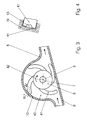
- Fig. 1 and especially in Fig. 2 is the engine block of an internal combustion engine with 1 and the water pump according to the invention summarily denoted by 2.
- a channel 3 is indicated, for example, in the event that the water pump operates the engine cooling circuit directly.
- the water pump 2 essentially comprises a housing 5 and a rotor 6.
- the rotor is seated non-rotatably on a rotor shaft 7 with the axis 9.
- the housing 5 is fastened to the engine block 1 by means of threaded bolts 13. It could also be made in one piece with the engine block 1.
- the housing 5 has the shape of a drum 10 with a bottom 11 on the side facing the engine block 1 and ends on the side facing away from it with an open edge 12 whose smallest diameter is larger than the largest diameter of the rotor 6.
- the drum has on its outer side an outer shoulder 15 and on its inner wall an inner shoulder 16.
- the drum 10 is closed by a lid 14 which is positioned by engagement with the inner shoulder 16 and by a spreader 17 is secured.
- the cover 14 has a bore 20 with a lip sealing ring 19 for the passage of the rotor shaft. 7
- the water pump 2 is here a rotary vane pump and the housing forms a cylindrical inner wall, a connecting piece 8 is in Fig. 1 to see. But it could also be a pump of other operation, such as a centrifugal pump. Then the bottom 11 would have an inlet opening and the drum would be in the form of a screw.
- a coupling plate 30 is provided for driving connection between the pulley ring 26 and the rotor shaft 7. It is detachably connected at its outer edge 28 by a number of bolts 31 with the pulley ring 26 and rotatably connected with its hub 32 with the rotor shaft 7.
- the outer edge of the dome disc 30 is located on an axially normal mating surface 34 of the pulley collar 26 and with the surface 24th on the outer ring of the bearing.
- the dome disk 30 between its outer edge and the hub 32 a number of openings through which the spreader 17 is accessible from the outside.
- the expansion ring 17 is pulled by approaching its ends from its groove and the bolts 31 are released. And already the dome disk 30 can be pulled out of the housing 5 together with the rotor 6 and the cover 14. Of this, the pulley ring 26 is not affected, he remains unchanged on his camp.
- Fig. 3 is as an addition to Fig. 2 to see a preferred embodiment of the water pump in cross section.
- the rotor 6 is arranged eccentrically (axis 7).
- the rotor 6 has a number of circumferentially distributed elastic wings 41, or it is made entirely of an elastic material.
- the direction of rotation of the rotor 6 is indicated by the arrow 42.
- the detail of Fig. 4 shows that the elastic wings 41 have outgoing recesses from their outer ends. They allow the passage of solid particles without damaging the wings 41.
Landscapes
- Engineering & Computer Science (AREA)
- Mechanical Engineering (AREA)
- General Engineering & Computer Science (AREA)
- Chemical & Material Sciences (AREA)
- Combustion & Propulsion (AREA)
- Structures Of Non-Positive Displacement Pumps (AREA)
Abstract
Description
- Die Erfindung betrifft Wasserpumpen, im Wesentlichen bestehend aus einem Gehäuse, einer Rotorwelle mit Pumprotor und einer mit der Welle verbundenen Riemenscheibe zum Antrieb der Pumpe mittels eines Keilriemens oder eines Zahnriemens.
- Der Antrieb solcher Pumpen erfolgt gewöhnlich mittels eines Keil-, Flach- oder Zahnriemens. Die treibende Riemenscheibe sitzt meist auf der Kurbelwelle einer Verbrennungskraftmaschine. Oft treibt derselbe Riemen mehrere Aggregate. Mittels Zahnriemen wird auch eine Nockenwelle angetrieben. In diesem Fall ist nicht nur die richtige Riemenspannung zu wahren, sondern auch der Synchronismus zwischen Kurbelwelle und Nockenwelle. Dieser nämlich bestimmt die Schließzeiten der Gaswechselventile.
- Zum Austausch von Teilen der Pumpe (Dichtungen, Lager, Rotor) muss bei bekannten Pumpen der Riemen gelöst und nach Austausch auch wieder gespannt und gegebenenfalls synchronisiert werden.
- Die
FR 2.230.225 - Aus der
JP 2004/052723 A - Es ist somit die der Erfindung zugrunde liegende Aufgabe, eine gattungsgemäße Pumpe so auszubilden, dass sie ohne Abnehmen des Treibriemens zerlegbar ist, und trotzdem eine stabile Lagerung der Rotorwelle mit einem einzigen Lager ermöglicht. Erfindungsgemäß wird das mit den kennzeichnenden Merkmalen des 1. Anspruchs erreicht.
- Das Gehäuse bildet einen den Pumprotor aufnehmenden Raum, dessen zylindrische Wand ohne Einschnürung endet. Dadurch kann der Pumprotor nach der offenen Seite aus dem Gehäuse gezogen werden. Der an der dem Boden abgewandten offenen Seite des Gehäuses eingesetzte ebenfalls ausziehbare Deckel mit einer Bohrung für den Durchtritt der Rotorwelle dient nur der Abdichtung des Raumes.
- Am äußeren Umfang der das Gehäuse bildenden Trommel sitzt ein Lager, auf dem ein zur Gänze außerhalb der Wand angeordneter Riemenscheibenkranz gelagert ist. Somit behindert das Lager nicht das Ausziehen des Rotors. Außerdem sichert der große Durchmesser des Lagers und sein kleiner axialer Abstand vom Pumprotor die präzise Führung des Rotors, obwohl er nur in einem einzigen Lager gelagert ist. Zur lösbaren Verbindung der Riemenscheibe mit dem Pumprotor ist an dem Riemenscheibenkranz eine Kuppelscheibe drehfest und abnehmbar angeschraubt. Die Kuppelscheibe ihrerseits ist mit der Rotorwelle drehfest verbunden oder gar mit ihr einstückig. Die Rotorwelle durchsetzt den Deckel von außen und ragt in den Pumpraum, in dem sie den Rotor trägt. Dadurch kann nach Lösen der Schraubverbindung zwischen Riemenscheibenkranz und Kuppelscheibe letztere mitsamt der Rotorwelle, dem Rotor und dem Deckel aus dem Gehäuse gezogen werden.
- Das Gehäuse ist entweder an einem Motorblock einer Verbrennungskraftmaschine befestigt (Anspruch 2) oder es ist im Motorblock oder einem Teil dessen selbst ausgebildet (Anspruch 3). Letzteres ist eine besonders kostengünstige Lösung, weil kein eigenes Pumpengehäuse benötigt wird. Außerdem kann so die Baulänge der Verbrennungskraftmaschine kürzer sein.
- In einer bevorzugten Ausführungsform hat die zylindrische Wand in der Region ihres vom Boden abgewandten Randes eine äußere Schulter und eine innere Schulter (Anspruch 4). So sind das Lager - ein Wälzlager, vorzugsweise ein Kugellager - und der Deckel genau positioniert. Demselben Zweck dient auch eine axiale Sicherung des Lagers und des Deckels durch in entsprechende Nuten der zylindrischen Wand eingesetzte Federringe (Anspruch 5). Die Federringe oder andere Sicherungsmittel sind von außen durch Durchbrüche in der Kuppelscheibe zugänglich (Anspruch 6).
- Die Abdichtung des Pumpraumes erfolgt vorzugsweise durch Dichtungen im Deckel, und zwar an seinem äußeren Rand durch einen ersten Dichtring und in der Bohrung durch einen zweiten Dichtring zur Abdichtung an der Rotorwelle (Anspruch 7). Weil beim Zerlegen der Pumpe der Deckel zusammen mit der Pumpwelle und der Kuppelscheibe aus dem Gehäuse gezogen wird, kann der so angeordnete zweite Dichtring, meist ein empfindlicher Lippendichtring, nicht beschädigt werden. Der erste Dichtring kann ein einfacher O-Ring sein, weil dort keine Relativbewegung.
- Die Erfindung eignet sich für Pumpen verschiedener Bauart: Zentrifugalpumpen, Seitenkanalpumpen, Flügelzellenpumpen. Bei Zentrifugalpumpen mündet der Zulauf zentral im Boden des Gehäuses, bei den beiden anderen Bauarten münden Zulauf und Ablauf in geeigneter Weise. Die Auswahl der Bauart hängt unterem anderen davon ab, ob sie reines Kühlwasser fördern soll, oder ob sie schmutziges Rohwasser aus der Umgebung (zum Beispiel bei Einsatz der Verbrennungskraftmaschine als Schiffsmotor) zum Wärmetausch mit dem geschlossenen Motorkühlkreislauf fördern soll.
- In letzterem Fall ist in einer bevorzugten Ausführungsform der Pumprotor ein Flügelrad mit elastisch flexiblen Flügeln, dessen Achse bezüglich der kreiszylindrischen Wand exzentrisch angeordnet ist (Anspruch 8). In einer zweckmäßigen Weiterbildung haben die flexiblen Flügel des Pumprotors von ihrer äußeren Kante nach innen verlaufende Aussparungen (Anspruch 9). Dadurch können größere Verunreinigungen den Pumprotor passieren ohne ihn zu beschädigen.
- Insgesamt wird mit der Erfindung das Hauptziel, ein Zerlegen der Pumpe ohne Abnehmen des Treibriemens bei einfacher und präziser Lagerung des Rotors zu ermöglichen, vollständig erreicht.
-
- Fig. 1:
- Einen Längsschnitt durch eine bevorzugte Ausführungsform der Erfindung,
- Fig. 2:
- Eine Frontalansicht nach II in
Fig. 1 . - Fig. 3:
- Schnitt nach III-III in
Fig. 2 . - Fig. 4:
- Detail IV-IV in
Fig. 3 . - In
Fig. 1 und vor allem inFig. 2 ist der Motorblock einer Verbrennungskraftmaschine mit 1 und die erfindungsgemäße Wasserpumpe summarisch mit 2 bezeichnet. Im Motorblock 1 ist ein Kanal 3 angedeutet, beispielsweise für den Fall dass die Wasserpumpe den Motorkühlkreislauf direkt bedient. - Die Wasserpumpe 2 umfasst im Wesentlichen ein Gehäuse 5 und einen Rotor 6. Der Rotor sitzt drehfest auf einer Rotorwelle 7 mit der Achse 9. Das Gehäuse 5 Ist mittels Schraubbolzen 13 am Motorblock 1 befestigt. Es könnte aber auch mit dem Motorblock 1 einstückig ausgeführt sein. Das Gehäuse 5 hat die Form einer Trommel 10 mit einem Boden 11 an der dem Motorblock 1 zugewandten Seite und endet an der ihm abgewandten Seite mit einem offenen Rand 12, dessen kleinster Durchmesser größer als der größte Durchmesser des Rotors 6 ist.
- Dadurch kann der Rotor 6 aus dem Gehäuse 5 herausgezogen werden. Weiters hat die Trommel an ihrer Außenseite eine äußere Schulter 15 und an ihrer Innenwand eine innere Schulter 16. An ihrer dem Motorblock 1 abgewandten Seite ist die Trommel 10 von einem Deckel 14 verschlossen, der durch Anlage an der innere Schulter 16 positioniert und von einem Spreizring 17 gesichert ist. Der Deckel 14 hat eine Bohrung 20 mit einem Lippendichtring 19 für den Durchtritt der Rotorwelle 7.
- Die Wasserpumpe 2 ist hier eine Drehflügelpumpe und das Gehäuse bildet eine zylindrische Innenwand, ein Anschlussstutzen 8 ist in
Fig. 1 zu sehen. Sie könnte aber auch eine Pumpe anderer Arbeitsweise, beispielsweise eine Zentrifugalpumpe sein. Dann hätte der Boden 11 eine Einlassöffnung und die Trommel die Form einer Schnecke. - Bemerkenswert ist die Lagerung aller rotierenden Teile in einem einzigen Wälzlager. Am äußeren Umfang der Trommel 10 sitzt ein als Festlager ausgebildetes Kugellager 22. Sein Innenring ist zwischen der äußeren Schulter 15 des Gehäuses 5 und einem Sprengring 25 und sein Außenring zwischen den achsnormalen Flächen 23 und 25 positioniert. Auf dem Kugellager 22 ist ein Riemenscheibenkranz 26, hier für einen Zahnriemen 27, gelagert. Es könnte aber auch ein irgendein Transmissionsriemen, beispielsweise ein Keilriemen sein.
- Zur treibenden Verbindung zwischen dem Riemenscheibenkranz 26 und der Rotorwelle 7 ist eine Kuppelscheibe 30 vorgesehen. Sie ist an ihrem äußeren Rand 28 durch eine Anzahl Bolzen 31 mit dem Riemenscheibenkranz 26 lösbar verbunden und mit ihrer Nabe 32 drehfest mit der Rotorwelle 7 verbunden. Zur genauen Positionierung liegt der äußere Rand der Kuppelscheibe 30 an einer achsnormalen Passfläche 34 des Riemenscheibenkranzes 26 und mit der Fläche 24 am Außenring des Wälzlagers an. Wie in
Fig. 1 zu sehen, hat die Kuppelscheibe 30 zwischen ihrem äußeren Rand und der Nabe 32 eine Anzahl Durchbrüche, durch die der Spreizring 17 von außen zugänglich ist. - Ist der Pumpenrotor 6 oder der Dichtring 19 auszuwechseln, wird der Spreizring 17 durch Annähern seiner Enden aus seiner Nut gezogen und werden die Bolzen 31 gelöst. Und schon kann die Kuppelscheibe 30 mitsamt dem Rotor 6 und dem Deckel 14 aus dem Gehäuse 5 gezogen werden. Davon ist der Riemenscheibenkranz 26 nicht betroffen, er bleibt unverrückt auf seinem Lager.
- In
Fig. 3 ist als Ergänzung zuFig. 2 noch eine bevorzugte Ausführungsform der Wasserpumpe im Querschnitt zu sehen. In dem von dem trommelförmigen Gehäuse 10 mit den Anschlussstutzen 8, 8' gebildeten Pumpraum 40 ist exzentrisch (Achse 7) der Rotor 6 angeordnet. Der Rotor 6 hat eine Anzahl über den Umfang verteilter elastischer Flügel 41, oder er besteht ganz aus einem elastischen Werkstoff. Der Drehsinn des Rotors 6 ist mit dem Pfeil 42 angezeigt. Das Detail derFig. 4 zeigt noch, dass die elastischen Flügel 41 von ihren äußeren Enden ausgehende Aussparungen haben. Sie erlauben den Durchtritt von festen Teilchen ohne die Flügel 41 zu beschädigen.
Claims (9)
- Wasserpumpe, im Wesentlichen bestehend aus einem Gehäuse (5), einer Rotorwelle (7) mit Pumprotor (6) und einer mit der Welle (7) verbundenen Riemenscheibe zum Antrieb der Pumpe mittels eines Treibriemens (27), dadurch gekennzeichnet, dassa) Das Gehäuse (5) aus einer Trommel (10) mit einem Boden (11) gebildet ist, und an der dem Boden (11) abgewandten Seite einen offenen Rand (12) hat,b) An der vom Boden (11) abgewandten offenen Seite der Trommel (10) ein Deckel (14) mit einer Bohrung (20) für den Durchtritt der Rotorwelle (7) eingesetzt istc) Am äußeren Umfang der Trommel (10) ein Lager (22) sitzt, auf dem ein Riemenscheibenkranz (26) gelagert ist, undd) Eine Kuppelscheibe (30) mit dem Riemenscheibenkranz (26) drehfest und abnehmbar und mit der Rotorwelle (7) drehfest verbunden (oder mit ihr einstückig) ist, wobei die Rotorwelle (7) den Deckel (14) durchsetzt.
- Wasserpumpe nach Anspruch 1, dadurch gekennzeichnet, dass das Gehäuse (5) am Motorblock (1) einer Verbrennungskraftmaschine oder einem Teil dessen angeschraubt ist.
- Wasserpumpe nach Anspruch 1, dadurch gekennzeichnet, dass das Gehäuse (5) mit dem Motorblock (1) einer Verbrennungskraftmaschine oder einem Teil dessen einstückig ist.
- Wasserpumpe nach Anspruch 1, dadurch gekennzeichnet, dass die Trommel (10) in der Region ihres Randes (12) eine äußere Schulter (15) und eine innere Schulter (16) hat, die äußere (15) zur Positionierung des Lagers (22) und die innere (16) zur Positionierung des Deckels (14).
- Wasserpumpe nach Anspruch 1, dadurch gekennzeichnet, dass das Lager (22) und der Deckel (14) durch Federringe (17,25) in axialer Richtung gesichert sind.
- Wasserpumpe nach Anspruch 1, dadurch gekennzeichnet, dass die Kuppelscheibe (30) Durchbrüche aufweist.
- Wasserpumpe nach Anspruch 1, dadurch gekennzeichnet, dass der Deckel (14) an seinem äußeren Rand einen ersten Dichtring (18) und in der Bohrung (20) einen zweiten Dichtring (19) aufnimmt.
- Wasserpumpe nach Anspruch 1, dadurch gekennzeichnet, dass der Pumprotor (6) ein Flügelrad mit elastisch flexiblen Flügeln (41) und dessen Achse (9) bezüglich der zylindrischen Innenwand der Trommel (10) exzentrisch angeordnet ist.
- Wasserpumpe nach Anspruch 8 dadurch gekennzeichnet, dass die flexiblen Flügel (41) des Pumprotors (6) von ihrer äußeren Kante (44) nach innen verlaufende Aussparungen (43) haben.
Applications Claiming Priority (1)
| Application Number | Priority Date | Filing Date | Title |
|---|---|---|---|
| AT0068310U AT12267U1 (de) | 2010-11-09 | 2010-11-09 | Wasserpumpe für eine verbrennungskraftmaschine |
Publications (3)
| Publication Number | Publication Date |
|---|---|
| EP2450547A2 true EP2450547A2 (de) | 2012-05-09 |
| EP2450547A3 EP2450547A3 (de) | 2016-11-09 |
| EP2450547B1 EP2450547B1 (de) | 2017-08-30 |
Family
ID=45217921
Family Applications (1)
| Application Number | Title | Priority Date | Filing Date |
|---|---|---|---|
| EP11008643.6A Not-in-force EP2450547B1 (de) | 2010-11-09 | 2011-10-28 | Wasserpumpe für eine Verbrennungskraftmaschine |
Country Status (2)
| Country | Link |
|---|---|
| EP (1) | EP2450547B1 (de) |
| AT (1) | AT12267U1 (de) |
Cited By (1)
| Publication number | Priority date | Publication date | Assignee | Title |
|---|---|---|---|---|
| CN115013136A (zh) * | 2021-03-04 | 2022-09-06 | 沃尔沃汽车公司 | 安装到曲轴的泵 |
Citations (2)
| Publication number | Priority date | Publication date | Assignee | Title |
|---|---|---|---|---|
| FR2230225A5 (de) | 1973-05-14 | 1974-12-13 | Peugeot & Renault | |
| JP2004052723A (ja) | 2002-07-23 | 2004-02-19 | Aisin Seiki Co Ltd | ウォーターポンプ |
Family Cites Families (3)
| Publication number | Priority date | Publication date | Assignee | Title |
|---|---|---|---|---|
| GB1461901A (en) * | 1975-06-23 | 1977-01-19 | Skf Uk Ltd | Water pumps for internal combustion engines |
| JPS5784331U (de) * | 1980-11-13 | 1982-05-25 | ||
| DE60128631T2 (de) * | 2000-09-19 | 2008-02-07 | Aisin Seiki K.K., Kariya | Wasserpumpe |
-
2010
- 2010-11-09 AT AT0068310U patent/AT12267U1/de not_active IP Right Cessation
-
2011
- 2011-10-28 EP EP11008643.6A patent/EP2450547B1/de not_active Not-in-force
Patent Citations (2)
| Publication number | Priority date | Publication date | Assignee | Title |
|---|---|---|---|---|
| FR2230225A5 (de) | 1973-05-14 | 1974-12-13 | Peugeot & Renault | |
| JP2004052723A (ja) | 2002-07-23 | 2004-02-19 | Aisin Seiki Co Ltd | ウォーターポンプ |
Cited By (2)
| Publication number | Priority date | Publication date | Assignee | Title |
|---|---|---|---|---|
| CN115013136A (zh) * | 2021-03-04 | 2022-09-06 | 沃尔沃汽车公司 | 安装到曲轴的泵 |
| CN115013136B (zh) * | 2021-03-04 | 2024-04-26 | 沃尔沃汽车公司 | 安装到曲轴的泵 |
Also Published As
| Publication number | Publication date |
|---|---|
| EP2450547A3 (de) | 2016-11-09 |
| AT12267U1 (de) | 2012-02-15 |
| EP2450547B1 (de) | 2017-08-30 |
Similar Documents
| Publication | Publication Date | Title |
|---|---|---|
| DE60216474T2 (de) | Berührungsfreie dichtung für anwendungen mit grossem achsversatz | |
| DE102013101185B4 (de) | Drehkolbenpumpe | |
| DE112007000514T5 (de) | Flügelpumpe mit reduziertem Rotoranordnungsdurchmesser | |
| EP1477636A2 (de) | Nockenwellenversteller für Verbrennungskraftmaschinen | |
| DE102013214240A1 (de) | Propellerblattlagerung | |
| DE102008013991A1 (de) | Pumpe oder Motor | |
| DE10260546A1 (de) | Brennkraftmaschine mit einer Vorrichtung zur hydraulischen Drehwinkelverstellung ihrer Nockenwelle gegenüber ihrer Kurbelwelle sowie mit einer Vakuumpumpe für einen Servoverbraucher, insbesondere für einen Bremskraftverstärker | |
| DE102014102708B4 (de) | Scrollpumpe mit trennbarer umlaufender Scrollplatte und Verfahren zum Austauschen einer Spitzendichtung | |
| DE102016100957A1 (de) | Verdrängerpumpe | |
| EP2112336A1 (de) | Gemeinsame Ölversorgung des VCT und der Nockenwellenlager über eine hohle Nockenwelle | |
| DE102016200939A1 (de) | Lagereinheit für einen Abgasturbolader oder eine Abgasnutzturbine | |
| EP2450547B1 (de) | Wasserpumpe für eine Verbrennungskraftmaschine | |
| EP2420651A2 (de) | Lageranordnung für die Verdichterseite eines Turboladers einer Verbrennungskraftmaschine | |
| DE2719168A1 (de) | Kreiselpumpe | |
| DE69719937T2 (de) | Spiralmaschine und lagerschmierung | |
| AT397994B (de) | Selbstfördereinrichtung für die schmierung eines auf einer welle oder achse angeordneten lagers | |
| DE112010001701T5 (de) | Flügelzellenpumpe mit verbessertem Rotor und Drehschiebererweiterungsring | |
| WO2005066496A1 (de) | Drehkolbenpumpe mit axial beweglichem flügel | |
| EP3032105B1 (de) | Mechanische kfz-vakuumpumpe | |
| DE102021133447A1 (de) | Magnetkupplungspumpenanordnung | |
| DE112006000321T5 (de) | Dichtungsstruktur einer Turbomolekularpumpe | |
| DE69211402T2 (de) | Vorrichtung zum Umwandeln einer drehenden Bewegung in eine oszillierende Bewegung | |
| DE102014214049A1 (de) | Turbomaschine mit Zentrifugaldichtung | |
| DE202011002172U1 (de) | Bolzenkupplung | |
| DE102021115440A1 (de) | Rotationspumpe mit einer Axialschubbegrenzungseinrichtung |
Legal Events
| Date | Code | Title | Description |
|---|---|---|---|
| PUAI | Public reference made under article 153(3) epc to a published international application that has entered the european phase |
Free format text: ORIGINAL CODE: 0009012 |
|
| AK | Designated contracting states |
Kind code of ref document: A2 Designated state(s): AL AT BE BG CH CY CZ DE DK EE ES FI FR GB GR HR HU IE IS IT LI LT LU LV MC MK MT NL NO PL PT RO RS SE SI SK SM TR |
|
| AX | Request for extension of the european patent |
Extension state: BA ME |
|
| PUAL | Search report despatched |
Free format text: ORIGINAL CODE: 0009013 |
|
| AK | Designated contracting states |
Kind code of ref document: A3 Designated state(s): AL AT BE BG CH CY CZ DE DK EE ES FI FR GB GR HR HU IE IS IT LI LT LU LV MC MK MT NL NO PL PT RO RS SE SI SK SM TR |
|
| AX | Request for extension of the european patent |
Extension state: BA ME |
|
| RIC1 | Information provided on ipc code assigned before grant |
Ipc: F02B 67/06 20060101ALN20161005BHEP Ipc: F01P 5/12 20060101AFI20161005BHEP |
|
| 17P | Request for examination filed |
Effective date: 20161201 |
|
| RIC1 | Information provided on ipc code assigned before grant |
Ipc: F01P 5/12 20060101AFI20170315BHEP Ipc: F02B 67/06 20060101ALN20170315BHEP |
|
| GRAP | Despatch of communication of intention to grant a patent |
Free format text: ORIGINAL CODE: EPIDOSNIGR1 |
|
| INTG | Intention to grant announced |
Effective date: 20170425 |
|
| GRAJ | Information related to disapproval of communication of intention to grant by the applicant or resumption of examination proceedings by the epo deleted |
Free format text: ORIGINAL CODE: EPIDOSDIGR1 |
|
| GRAP | Despatch of communication of intention to grant a patent |
Free format text: ORIGINAL CODE: EPIDOSNIGR1 |
|
| GRAS | Grant fee paid |
Free format text: ORIGINAL CODE: EPIDOSNIGR3 |
|
| INTC | Intention to grant announced (deleted) | ||
| INTG | Intention to grant announced |
Effective date: 20170531 |
|
| RIC1 | Information provided on ipc code assigned before grant |
Ipc: F02B 67/06 20060101ALN20170519BHEP Ipc: F01P 5/12 20060101AFI20170519BHEP |
|
| GRAA | (expected) grant |
Free format text: ORIGINAL CODE: 0009210 |
|
| AK | Designated contracting states |
Kind code of ref document: B1 Designated state(s): AL AT BE BG CH CY CZ DE DK EE ES FI FR GB GR HR HU IE IS IT LI LT LU LV MC MK MT NL NO PL PT RO RS SE SI SK SM TR |
|
| REG | Reference to a national code |
Ref country code: GB Ref legal event code: FG4D Free format text: NOT ENGLISH |
|
| REG | Reference to a national code |
Ref country code: CH Ref legal event code: EP |
|
| REG | Reference to a national code |
Ref country code: AT Ref legal event code: REF Ref document number: 923794 Country of ref document: AT Kind code of ref document: T Effective date: 20170915 |
|
| REG | Reference to a national code |
Ref country code: IE Ref legal event code: FG4D Free format text: LANGUAGE OF EP DOCUMENT: GERMAN |
|
| REG | Reference to a national code |
Ref country code: DE Ref legal event code: R096 Ref document number: 502011012878 Country of ref document: DE |
|
| REG | Reference to a national code |
Ref country code: FR Ref legal event code: PLFP Year of fee payment: 7 |
|
| REG | Reference to a national code |
Ref country code: NL Ref legal event code: MP Effective date: 20170830 |
|
| REG | Reference to a national code |
Ref country code: LT Ref legal event code: MG4D |
|
| PG25 | Lapsed in a contracting state [announced via postgrant information from national office to epo] |
Ref country code: SE Free format text: LAPSE BECAUSE OF FAILURE TO SUBMIT A TRANSLATION OF THE DESCRIPTION OR TO PAY THE FEE WITHIN THE PRESCRIBED TIME-LIMIT Effective date: 20170830 Ref country code: HR Free format text: LAPSE BECAUSE OF FAILURE TO SUBMIT A TRANSLATION OF THE DESCRIPTION OR TO PAY THE FEE WITHIN THE PRESCRIBED TIME-LIMIT Effective date: 20170830 Ref country code: LT Free format text: LAPSE BECAUSE OF FAILURE TO SUBMIT A TRANSLATION OF THE DESCRIPTION OR TO PAY THE FEE WITHIN THE PRESCRIBED TIME-LIMIT Effective date: 20170830 Ref country code: FI Free format text: LAPSE BECAUSE OF FAILURE TO SUBMIT A TRANSLATION OF THE DESCRIPTION OR TO PAY THE FEE WITHIN THE PRESCRIBED TIME-LIMIT Effective date: 20170830 Ref country code: NO Free format text: LAPSE BECAUSE OF FAILURE TO SUBMIT A TRANSLATION OF THE DESCRIPTION OR TO PAY THE FEE WITHIN THE PRESCRIBED TIME-LIMIT Effective date: 20171130 |
|
| PG25 | Lapsed in a contracting state [announced via postgrant information from national office to epo] |
Ref country code: LV Free format text: LAPSE BECAUSE OF FAILURE TO SUBMIT A TRANSLATION OF THE DESCRIPTION OR TO PAY THE FEE WITHIN THE PRESCRIBED TIME-LIMIT Effective date: 20170830 Ref country code: BG Free format text: LAPSE BECAUSE OF FAILURE TO SUBMIT A TRANSLATION OF THE DESCRIPTION OR TO PAY THE FEE WITHIN THE PRESCRIBED TIME-LIMIT Effective date: 20171130 Ref country code: GR Free format text: LAPSE BECAUSE OF FAILURE TO SUBMIT A TRANSLATION OF THE DESCRIPTION OR TO PAY THE FEE WITHIN THE PRESCRIBED TIME-LIMIT Effective date: 20171201 Ref country code: RS Free format text: LAPSE BECAUSE OF FAILURE TO SUBMIT A TRANSLATION OF THE DESCRIPTION OR TO PAY THE FEE WITHIN THE PRESCRIBED TIME-LIMIT Effective date: 20170830 Ref country code: IS Free format text: LAPSE BECAUSE OF FAILURE TO SUBMIT A TRANSLATION OF THE DESCRIPTION OR TO PAY THE FEE WITHIN THE PRESCRIBED TIME-LIMIT Effective date: 20171230 Ref country code: ES Free format text: LAPSE BECAUSE OF FAILURE TO SUBMIT A TRANSLATION OF THE DESCRIPTION OR TO PAY THE FEE WITHIN THE PRESCRIBED TIME-LIMIT Effective date: 20170830 |
|
| PG25 | Lapsed in a contracting state [announced via postgrant information from national office to epo] |
Ref country code: NL Free format text: LAPSE BECAUSE OF FAILURE TO SUBMIT A TRANSLATION OF THE DESCRIPTION OR TO PAY THE FEE WITHIN THE PRESCRIBED TIME-LIMIT Effective date: 20170830 |
|
| PG25 | Lapsed in a contracting state [announced via postgrant information from national office to epo] |
Ref country code: CZ Free format text: LAPSE BECAUSE OF FAILURE TO SUBMIT A TRANSLATION OF THE DESCRIPTION OR TO PAY THE FEE WITHIN THE PRESCRIBED TIME-LIMIT Effective date: 20170830 Ref country code: DK Free format text: LAPSE BECAUSE OF FAILURE TO SUBMIT A TRANSLATION OF THE DESCRIPTION OR TO PAY THE FEE WITHIN THE PRESCRIBED TIME-LIMIT Effective date: 20170830 Ref country code: PL Free format text: LAPSE BECAUSE OF FAILURE TO SUBMIT A TRANSLATION OF THE DESCRIPTION OR TO PAY THE FEE WITHIN THE PRESCRIBED TIME-LIMIT Effective date: 20170830 Ref country code: RO Free format text: LAPSE BECAUSE OF FAILURE TO SUBMIT A TRANSLATION OF THE DESCRIPTION OR TO PAY THE FEE WITHIN THE PRESCRIBED TIME-LIMIT Effective date: 20170830 |
|
| PG25 | Lapsed in a contracting state [announced via postgrant information from national office to epo] |
Ref country code: IT Free format text: LAPSE BECAUSE OF FAILURE TO SUBMIT A TRANSLATION OF THE DESCRIPTION OR TO PAY THE FEE WITHIN THE PRESCRIBED TIME-LIMIT Effective date: 20170830 Ref country code: MC Free format text: LAPSE BECAUSE OF FAILURE TO SUBMIT A TRANSLATION OF THE DESCRIPTION OR TO PAY THE FEE WITHIN THE PRESCRIBED TIME-LIMIT Effective date: 20170830 Ref country code: SM Free format text: LAPSE BECAUSE OF FAILURE TO SUBMIT A TRANSLATION OF THE DESCRIPTION OR TO PAY THE FEE WITHIN THE PRESCRIBED TIME-LIMIT Effective date: 20170830 Ref country code: EE Free format text: LAPSE BECAUSE OF FAILURE TO SUBMIT A TRANSLATION OF THE DESCRIPTION OR TO PAY THE FEE WITHIN THE PRESCRIBED TIME-LIMIT Effective date: 20170830 Ref country code: SK Free format text: LAPSE BECAUSE OF FAILURE TO SUBMIT A TRANSLATION OF THE DESCRIPTION OR TO PAY THE FEE WITHIN THE PRESCRIBED TIME-LIMIT Effective date: 20170830 |
|
| REG | Reference to a national code |
Ref country code: CH Ref legal event code: PL Ref country code: DE Ref legal event code: R097 Ref document number: 502011012878 Country of ref document: DE |
|
| PLBE | No opposition filed within time limit |
Free format text: ORIGINAL CODE: 0009261 |
|
| STAA | Information on the status of an ep patent application or granted ep patent |
Free format text: STATUS: NO OPPOSITION FILED WITHIN TIME LIMIT |
|
| GBPC | Gb: european patent ceased through non-payment of renewal fee |
Effective date: 20171130 |
|
| REG | Reference to a national code |
Ref country code: IE Ref legal event code: MM4A |
|
| PG25 | Lapsed in a contracting state [announced via postgrant information from national office to epo] |
Ref country code: CH Free format text: LAPSE BECAUSE OF NON-PAYMENT OF DUE FEES Effective date: 20171031 Ref country code: LU Free format text: LAPSE BECAUSE OF NON-PAYMENT OF DUE FEES Effective date: 20171028 Ref country code: LI Free format text: LAPSE BECAUSE OF NON-PAYMENT OF DUE FEES Effective date: 20171031 |
|
| 26N | No opposition filed |
Effective date: 20180531 |
|
| REG | Reference to a national code |
Ref country code: BE Ref legal event code: MM Effective date: 20171031 |
|
| PG25 | Lapsed in a contracting state [announced via postgrant information from national office to epo] |
Ref country code: SI Free format text: LAPSE BECAUSE OF FAILURE TO SUBMIT A TRANSLATION OF THE DESCRIPTION OR TO PAY THE FEE WITHIN THE PRESCRIBED TIME-LIMIT Effective date: 20170830 Ref country code: BE Free format text: LAPSE BECAUSE OF NON-PAYMENT OF DUE FEES Effective date: 20171031 |
|
| PG25 | Lapsed in a contracting state [announced via postgrant information from national office to epo] |
Ref country code: MT Free format text: LAPSE BECAUSE OF FAILURE TO SUBMIT A TRANSLATION OF THE DESCRIPTION OR TO PAY THE FEE WITHIN THE PRESCRIBED TIME-LIMIT Effective date: 20170830 |
|
| PG25 | Lapsed in a contracting state [announced via postgrant information from national office to epo] |
Ref country code: IE Free format text: LAPSE BECAUSE OF NON-PAYMENT OF DUE FEES Effective date: 20171028 |
|
| PG25 | Lapsed in a contracting state [announced via postgrant information from national office to epo] |
Ref country code: GB Free format text: LAPSE BECAUSE OF NON-PAYMENT OF DUE FEES Effective date: 20171130 |
|
| REG | Reference to a national code |
Ref country code: AT Ref legal event code: MM01 Ref document number: 923794 Country of ref document: AT Kind code of ref document: T Effective date: 20171028 |
|
| PG25 | Lapsed in a contracting state [announced via postgrant information from national office to epo] |
Ref country code: AT Free format text: LAPSE BECAUSE OF NON-PAYMENT OF DUE FEES Effective date: 20171028 |
|
| PGFP | Annual fee paid to national office [announced via postgrant information from national office to epo] |
Ref country code: FR Payment date: 20181231 Year of fee payment: 8 |
|
| PGFP | Annual fee paid to national office [announced via postgrant information from national office to epo] |
Ref country code: DE Payment date: 20181228 Year of fee payment: 8 |
|
| PG25 | Lapsed in a contracting state [announced via postgrant information from national office to epo] |
Ref country code: HU Free format text: LAPSE BECAUSE OF FAILURE TO SUBMIT A TRANSLATION OF THE DESCRIPTION OR TO PAY THE FEE WITHIN THE PRESCRIBED TIME-LIMIT; INVALID AB INITIO Effective date: 20111028 |
|
| PG25 | Lapsed in a contracting state [announced via postgrant information from national office to epo] |
Ref country code: CY Free format text: LAPSE BECAUSE OF NON-PAYMENT OF DUE FEES Effective date: 20170830 |
|
| PG25 | Lapsed in a contracting state [announced via postgrant information from national office to epo] |
Ref country code: MK Free format text: LAPSE BECAUSE OF FAILURE TO SUBMIT A TRANSLATION OF THE DESCRIPTION OR TO PAY THE FEE WITHIN THE PRESCRIBED TIME-LIMIT Effective date: 20170830 |
|
| PG25 | Lapsed in a contracting state [announced via postgrant information from national office to epo] |
Ref country code: TR Free format text: LAPSE BECAUSE OF FAILURE TO SUBMIT A TRANSLATION OF THE DESCRIPTION OR TO PAY THE FEE WITHIN THE PRESCRIBED TIME-LIMIT Effective date: 20170830 |
|
| REG | Reference to a national code |
Ref country code: DE Ref legal event code: R119 Ref document number: 502011012878 Country of ref document: DE |
|
| PG25 | Lapsed in a contracting state [announced via postgrant information from national office to epo] |
Ref country code: PT Free format text: LAPSE BECAUSE OF FAILURE TO SUBMIT A TRANSLATION OF THE DESCRIPTION OR TO PAY THE FEE WITHIN THE PRESCRIBED TIME-LIMIT Effective date: 20170830 |
|
| PG25 | Lapsed in a contracting state [announced via postgrant information from national office to epo] |
Ref country code: AL Free format text: LAPSE BECAUSE OF FAILURE TO SUBMIT A TRANSLATION OF THE DESCRIPTION OR TO PAY THE FEE WITHIN THE PRESCRIBED TIME-LIMIT Effective date: 20170830 Ref country code: DE Free format text: LAPSE BECAUSE OF NON-PAYMENT OF DUE FEES Effective date: 20200501 |
|
| PG25 | Lapsed in a contracting state [announced via postgrant information from national office to epo] |
Ref country code: FR Free format text: LAPSE BECAUSE OF NON-PAYMENT OF DUE FEES Effective date: 20191031 |