EP2450471A1 - Procédé d'application de matériaux et de réparation d'un composant un composant - Google Patents
Procédé d'application de matériaux et de réparation d'un composant un composant Download PDFInfo
- Publication number
- EP2450471A1 EP2450471A1 EP10189840A EP10189840A EP2450471A1 EP 2450471 A1 EP2450471 A1 EP 2450471A1 EP 10189840 A EP10189840 A EP 10189840A EP 10189840 A EP10189840 A EP 10189840A EP 2450471 A1 EP2450471 A1 EP 2450471A1
- Authority
- EP
- European Patent Office
- Prior art keywords
- porous structure
- component
- recess
- substrate
- combustion chamber
- Prior art date
- Legal status (The legal status is an assumption and is not a legal conclusion. Google has not performed a legal analysis and makes no representation as to the accuracy of the status listed.)
- Withdrawn
Links
Images


Classifications
-
- C—CHEMISTRY; METALLURGY
- C23—COATING METALLIC MATERIAL; COATING MATERIAL WITH METALLIC MATERIAL; CHEMICAL SURFACE TREATMENT; DIFFUSION TREATMENT OF METALLIC MATERIAL; COATING BY VACUUM EVAPORATION, BY SPUTTERING, BY ION IMPLANTATION OR BY CHEMICAL VAPOUR DEPOSITION, IN GENERAL; INHIBITING CORROSION OF METALLIC MATERIAL OR INCRUSTATION IN GENERAL
- C23C—COATING METALLIC MATERIAL; COATING MATERIAL WITH METALLIC MATERIAL; SURFACE TREATMENT OF METALLIC MATERIAL BY DIFFUSION INTO THE SURFACE, BY CHEMICAL CONVERSION OR SUBSTITUTION; COATING BY VACUUM EVAPORATION, BY SPUTTERING, BY ION IMPLANTATION OR BY CHEMICAL VAPOUR DEPOSITION, IN GENERAL
- C23C24/00—Coating starting from inorganic powder
- C23C24/08—Coating starting from inorganic powder by application of heat or pressure and heat
- C23C24/10—Coating starting from inorganic powder by application of heat or pressure and heat with intermediate formation of a liquid phase in the layer
-
- B—PERFORMING OPERATIONS; TRANSPORTING
- B22—CASTING; POWDER METALLURGY
- B22F—WORKING METALLIC POWDER; MANUFACTURE OF ARTICLES FROM METALLIC POWDER; MAKING METALLIC POWDER; APPARATUS OR DEVICES SPECIALLY ADAPTED FOR METALLIC POWDER
- B22F3/00—Manufacture of workpieces or articles from metallic powder characterised by the manner of compacting or sintering; Apparatus specially adapted therefor ; Presses and furnaces
- B22F3/24—After-treatment of workpieces or articles
- B22F3/26—Impregnating
-
- B—PERFORMING OPERATIONS; TRANSPORTING
- B22—CASTING; POWDER METALLURGY
- B22F—WORKING METALLIC POWDER; MANUFACTURE OF ARTICLES FROM METALLIC POWDER; MAKING METALLIC POWDER; APPARATUS OR DEVICES SPECIALLY ADAPTED FOR METALLIC POWDER
- B22F7/00—Manufacture of composite layers, workpieces, or articles, comprising metallic powder, by sintering the powder, with or without compacting wherein at least one part is obtained by sintering or compression
- B22F7/002—Manufacture of composite layers, workpieces, or articles, comprising metallic powder, by sintering the powder, with or without compacting wherein at least one part is obtained by sintering or compression of porous nature
- B22F7/004—Manufacture of composite layers, workpieces, or articles, comprising metallic powder, by sintering the powder, with or without compacting wherein at least one part is obtained by sintering or compression of porous nature comprising at least one non-porous part
-
- B—PERFORMING OPERATIONS; TRANSPORTING
- B22—CASTING; POWDER METALLURGY
- B22F—WORKING METALLIC POWDER; MANUFACTURE OF ARTICLES FROM METALLIC POWDER; MAKING METALLIC POWDER; APPARATUS OR DEVICES SPECIALLY ADAPTED FOR METALLIC POWDER
- B22F7/00—Manufacture of composite layers, workpieces, or articles, comprising metallic powder, by sintering the powder, with or without compacting wherein at least one part is obtained by sintering or compression
- B22F7/06—Manufacture of composite layers, workpieces, or articles, comprising metallic powder, by sintering the powder, with or without compacting wherein at least one part is obtained by sintering or compression of composite workpieces or articles from parts, e.g. to form tipped tools
- B22F7/062—Manufacture of composite layers, workpieces, or articles, comprising metallic powder, by sintering the powder, with or without compacting wherein at least one part is obtained by sintering or compression of composite workpieces or articles from parts, e.g. to form tipped tools involving the connection or repairing of preformed parts
-
- B—PERFORMING OPERATIONS; TRANSPORTING
- B23—MACHINE TOOLS; METAL-WORKING NOT OTHERWISE PROVIDED FOR
- B23K—SOLDERING OR UNSOLDERING; WELDING; CLADDING OR PLATING BY SOLDERING OR WELDING; CUTTING BY APPLYING HEAT LOCALLY, e.g. FLAME CUTTING; WORKING BY LASER BEAM
- B23K1/00—Soldering, e.g. brazing, or unsoldering
- B23K1/0008—Soldering, e.g. brazing, or unsoldering specially adapted for particular articles or work
- B23K1/0018—Brazing of turbine parts
-
- B—PERFORMING OPERATIONS; TRANSPORTING
- B23—MACHINE TOOLS; METAL-WORKING NOT OTHERWISE PROVIDED FOR
- B23P—METAL-WORKING NOT OTHERWISE PROVIDED FOR; COMBINED OPERATIONS; UNIVERSAL MACHINE TOOLS
- B23P6/00—Restoring or reconditioning objects
- B23P6/002—Repairing turbine components, e.g. moving or stationary blades, rotors
- B23P6/007—Repairing turbine components, e.g. moving or stationary blades, rotors using only additive methods, e.g. build-up welding
-
- C—CHEMISTRY; METALLURGY
- C23—COATING METALLIC MATERIAL; COATING MATERIAL WITH METALLIC MATERIAL; CHEMICAL SURFACE TREATMENT; DIFFUSION TREATMENT OF METALLIC MATERIAL; COATING BY VACUUM EVAPORATION, BY SPUTTERING, BY ION IMPLANTATION OR BY CHEMICAL VAPOUR DEPOSITION, IN GENERAL; INHIBITING CORROSION OF METALLIC MATERIAL OR INCRUSTATION IN GENERAL
- C23C—COATING METALLIC MATERIAL; COATING MATERIAL WITH METALLIC MATERIAL; SURFACE TREATMENT OF METALLIC MATERIAL BY DIFFUSION INTO THE SURFACE, BY CHEMICAL CONVERSION OR SUBSTITUTION; COATING BY VACUUM EVAPORATION, BY SPUTTERING, BY ION IMPLANTATION OR BY CHEMICAL VAPOUR DEPOSITION, IN GENERAL
- C23C24/00—Coating starting from inorganic powder
- C23C24/08—Coating starting from inorganic powder by application of heat or pressure and heat
- C23C24/10—Coating starting from inorganic powder by application of heat or pressure and heat with intermediate formation of a liquid phase in the layer
- C23C24/103—Coating with metallic material, i.e. metals or metal alloys, optionally comprising hard particles, e.g. oxides, carbides or nitrides
-
- F—MECHANICAL ENGINEERING; LIGHTING; HEATING; WEAPONS; BLASTING
- F01—MACHINES OR ENGINES IN GENERAL; ENGINE PLANTS IN GENERAL; STEAM ENGINES
- F01D—NON-POSITIVE DISPLACEMENT MACHINES OR ENGINES, e.g. STEAM TURBINES
- F01D5/00—Blades; Blade-carrying members; Heating, heat-insulating, cooling or antivibration means on the blades or the members
- F01D5/005—Repairing methods or devices
-
- B—PERFORMING OPERATIONS; TRANSPORTING
- B23—MACHINE TOOLS; METAL-WORKING NOT OTHERWISE PROVIDED FOR
- B23K—SOLDERING OR UNSOLDERING; WELDING; CLADDING OR PLATING BY SOLDERING OR WELDING; CUTTING BY APPLYING HEAT LOCALLY, e.g. FLAME CUTTING; WORKING BY LASER BEAM
- B23K2101/00—Articles made by soldering, welding or cutting
- B23K2101/001—Turbines
-
- B—PERFORMING OPERATIONS; TRANSPORTING
- B29—WORKING OF PLASTICS; WORKING OF SUBSTANCES IN A PLASTIC STATE IN GENERAL
- B29C—SHAPING OR JOINING OF PLASTICS; SHAPING OF MATERIAL IN A PLASTIC STATE, NOT OTHERWISE PROVIDED FOR; AFTER-TREATMENT OF THE SHAPED PRODUCTS, e.g. REPAIRING
- B29C64/00—Additive manufacturing, i.e. manufacturing of three-dimensional [3D] objects by additive deposition, additive agglomeration or additive layering, e.g. by 3D printing, stereolithography or selective laser sintering
- B29C64/10—Processes of additive manufacturing
- B29C64/106—Processes of additive manufacturing using only liquids or viscous materials, e.g. depositing a continuous bead of viscous material
- B29C64/124—Processes of additive manufacturing using only liquids or viscous materials, e.g. depositing a continuous bead of viscous material using layers of liquid which are selectively solidified
- B29C64/129—Processes of additive manufacturing using only liquids or viscous materials, e.g. depositing a continuous bead of viscous material using layers of liquid which are selectively solidified characterised by the energy source therefor, e.g. by global irradiation combined with a mask
- B29C64/135—Processes of additive manufacturing using only liquids or viscous materials, e.g. depositing a continuous bead of viscous material using layers of liquid which are selectively solidified characterised by the energy source therefor, e.g. by global irradiation combined with a mask the energy source being concentrated, e.g. scanning lasers or focused light sources
-
- F—MECHANICAL ENGINEERING; LIGHTING; HEATING; WEAPONS; BLASTING
- F05—INDEXING SCHEMES RELATING TO ENGINES OR PUMPS IN VARIOUS SUBCLASSES OF CLASSES F01-F04
- F05D—INDEXING SCHEME FOR ASPECTS RELATING TO NON-POSITIVE-DISPLACEMENT MACHINES OR ENGINES, GAS-TURBINES OR JET-PROPULSION PLANTS
- F05D2230/00—Manufacture
- F05D2230/20—Manufacture essentially without removing material
- F05D2230/23—Manufacture essentially without removing material by permanently joining parts together
- F05D2230/232—Manufacture essentially without removing material by permanently joining parts together by welding
- F05D2230/237—Brazing
-
- F—MECHANICAL ENGINEERING; LIGHTING; HEATING; WEAPONS; BLASTING
- F05—INDEXING SCHEMES RELATING TO ENGINES OR PUMPS IN VARIOUS SUBCLASSES OF CLASSES F01-F04
- F05D—INDEXING SCHEME FOR ASPECTS RELATING TO NON-POSITIVE-DISPLACEMENT MACHINES OR ENGINES, GAS-TURBINES OR JET-PROPULSION PLANTS
- F05D2230/00—Manufacture
- F05D2230/20—Manufacture essentially without removing material
- F05D2230/23—Manufacture essentially without removing material by permanently joining parts together
- F05D2230/232—Manufacture essentially without removing material by permanently joining parts together by welding
- F05D2230/238—Soldering
-
- F—MECHANICAL ENGINEERING; LIGHTING; HEATING; WEAPONS; BLASTING
- F05—INDEXING SCHEMES RELATING TO ENGINES OR PUMPS IN VARIOUS SUBCLASSES OF CLASSES F01-F04
- F05D—INDEXING SCHEME FOR ASPECTS RELATING TO NON-POSITIVE-DISPLACEMENT MACHINES OR ENGINES, GAS-TURBINES OR JET-PROPULSION PLANTS
- F05D2230/00—Manufacture
- F05D2230/30—Manufacture with deposition of material
- F05D2230/31—Layer deposition
- F05D2230/312—Layer deposition by plasma spraying
-
- F—MECHANICAL ENGINEERING; LIGHTING; HEATING; WEAPONS; BLASTING
- F05—INDEXING SCHEMES RELATING TO ENGINES OR PUMPS IN VARIOUS SUBCLASSES OF CLASSES F01-F04
- F05D—INDEXING SCHEME FOR ASPECTS RELATING TO NON-POSITIVE-DISPLACEMENT MACHINES OR ENGINES, GAS-TURBINES OR JET-PROPULSION PLANTS
- F05D2230/00—Manufacture
- F05D2230/30—Manufacture with deposition of material
- F05D2230/31—Layer deposition
- F05D2230/313—Layer deposition by physical vapour deposition
-
- Y—GENERAL TAGGING OF NEW TECHNOLOGICAL DEVELOPMENTS; GENERAL TAGGING OF CROSS-SECTIONAL TECHNOLOGIES SPANNING OVER SEVERAL SECTIONS OF THE IPC; TECHNICAL SUBJECTS COVERED BY FORMER USPC CROSS-REFERENCE ART COLLECTIONS [XRACs] AND DIGESTS
- Y02—TECHNOLOGIES OR APPLICATIONS FOR MITIGATION OR ADAPTATION AGAINST CLIMATE CHANGE
- Y02T—CLIMATE CHANGE MITIGATION TECHNOLOGIES RELATED TO TRANSPORTATION
- Y02T50/00—Aeronautics or air transport
- Y02T50/60—Efficient propulsion technologies, e.g. for aircraft
Definitions
- the invention relates to a method for material application, in which a porous structure and a solder is used and a component.
- Recesses of blown-out cracks or larger cracks are laser-filled and repaired. However, the heat input is often too large and cracks form on the connection surface.
- Soldering methods can also be used, but the strength of the solder or the connection of the soldering material to the substrate is not always sufficient.
- the object is achieved by a method according to claim 1 in a component according to claim 7.
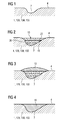
- FIG. 1 a substrate 1 of a component 120, 130, 155, preferably with a recess 7 is shown.
- the substrate 1 preferably comprises a superalloy according to FIG. 8 It preferably consists of one of these superalloys.
- the substrate 1 is preferably used for a turbine blade 120, 130 or a combustion chamber or a member 155 of a combustion chamber, wherein these for turbines of a steam or gas turbine 100 (FIGS. Fig. 5 ) can be used.
- a porous structure 10 is generated in a first step, preferably by a rapid prototype method, preferably directly on the substrate 1 or directly in the recess 7, a porous structure 10 is generated. This can be done by a sintering process or a melt process. In this case, a preferably laser or electron beam is used.
- the porous structure 10 is fusion-metallurgically bonded to the recess 7, at least mechanically.
- the powder can be sintered or melted. Melting has the advantage that molten metallurgical connections 19 of the porous structure 10 form on the boundary wall 22 of the substrate 1 within the depression 7 or on the substrate 1.
- the porous structure 10 may be any of those used in prior art processes to produce porous structures, where the porosity is open porosity but may have gradients in shape and distribution in any direction.
- the porous structure 10 may preferably be formed by beams whose contact points are interconnected by sintering or generally preferably by fusion metallurgy.
- the porous structure 10 can also be a prefabricated solid material (foam, mat), which is connected to the contact surface 20 of the trough, in particular by fusion metallurgy.
- individual wires can be introduced, which are connected at their ends 19 with the contact surface 20 of the recess 7, in particular by fusion metallurgy.
- the porous structure 10 preferably extends over the entire volume to be filled or applied.
- a brazing material 13 is preferably applied ( FIG. 3 ) and by a heat treatment, the liquid solder material 13 penetrates the porous structure 10 and forms a volume 16 that fills the recess 7. Other methods for filling with solder are possible.
- the materials for the porous structure 10 and the solder material 13 are different, i. they have different melting points (preferably at least 10K).
- the material for the porous structure 10 is a material having a melting temperature equal to or higher than the material of the substrate 1, or at least 10K higher than the solder material.
- the material for the porous structure 10 is the same or just a slightly modified material of the substrate 1.
- solder material 13 any of the prior art solder materials may be used for high temperature applications.
- FIG. 5 shows by way of example a gas turbine 100 in a longitudinal partial section.
- the gas turbine 100 has inside a rotatably mounted about a rotation axis 102 rotor 103 with a shaft 101, which is also referred to as a turbine runner.
- an intake housing 104 a compressor 105, for example, a toroidal combustion chamber 110, in particular annular combustion chamber, with a plurality of coaxially arranged burners 107, a turbine 108 and the exhaust housing 109th
- a compressor 105 for example, a toroidal combustion chamber 110, in particular annular combustion chamber, with a plurality of coaxially arranged burners 107, a turbine 108 and the exhaust housing 109th
- the annular combustion chamber 110 communicates with an annular annular hot gas channel 111, for example.
- annular annular hot gas channel 111 for example.
- turbine stages 112 connected in series form the turbine 108.
- Each turbine stage 112 is formed, for example, from two blade rings. As seen in the direction of flow of a working medium 113, in the hot gas channel 111 of a row of guide vanes 115, a series 125 formed of rotor blades 120 follows.
- the guide vanes 130 are fastened to an inner housing 138 of a stator 143, whereas the moving blades 120 of a row 125 are attached to the rotor 103 by means of a turbine disk 133, for example.
- air 105 is sucked in and compressed by the compressor 105 through the intake housing 104.
- the compressed air provided at the turbine-side end of the compressor 105 is supplied to the burners 107 where it is mixed with a fuel.
- the mixture is then burned to form the working fluid 113 in the combustion chamber 110.
- the working medium 113 flows along the hot gas channel 111 past the guide vanes 130 and the rotor blades 120.
- the working medium 113 relaxes on the rotor blades 120 in a pulse-transmitting manner, so that the blades 120 drive the rotor 103 and drive the machine coupled to it.
- the components exposed to the hot working medium 113 are subject to thermal loads during operation of the gas turbine 100.
- the guide vanes 130 and rotor blades 120 of the first turbine stage 112, viewed in the flow direction of the working medium 113, are subjected to the greatest thermal stress in addition to the heat shield elements lining the annular combustion chamber 110.
- substrates of the components may have a directional structure, i. they are monocrystalline (SX structure) or have only longitudinal grains (DS structure).
- iron-, nickel- or cobalt-based superalloys are used as the material for the components, in particular for the turbine blade 120, 130 and components of the combustion chamber 110.
- Such superalloys are for example from EP 1 204 776 B1 .
- EP 1 306 454 .
- the blades 120, 130 may be anti-corrosion coatings (MCrAlX; M is at least one element of the group iron (Fe), cobalt (Co), nickel (Ni), X is an active element and is yttrium (Y) and / or silicon , Scandium (Sc) and / or at least one element of the rare earth or hafnium).
- M is at least one element of the group iron (Fe), cobalt (Co), nickel (Ni)
- X is an active element and is yttrium (Y) and / or silicon , Scandium (Sc) and / or at least one element of the rare earth or hafnium).
- Such alloys are known from the EP 0 486 489 B1 .
- EP 0 412 397 B1 or EP 1 306 454 A1 are known from the EP 0 486 489 B1 .
- MCrAlX may still be present a thermal barrier coating, and consists for example of ZrO 2 , Y 2 O 3 -ZrO 2 , that is, it is not, partially or completely stabilized by yttria and / or calcium oxide and / or magnesium oxide.
- the vane 130 has a guide vane foot (not shown here) facing the inner housing 138 of the turbine 108 and a vane head opposite the vane foot.
- the vane head faces the rotor 103 and fixed to a mounting ring 140 of the stator 143.
- FIG. 6 shows a perspective view of a blade 120 or guide vane 130 of a turbomachine, which extends along a longitudinal axis 121.
- the turbomachine may be a gas turbine of an aircraft or a power plant for power generation, a steam turbine or a compressor.
- the blade 120, 130 has along the longitudinal axis 121 consecutively a fastening region 400, a blade platform 403 adjacent thereto and an airfoil 406 and a blade tip 415.
- the blade 130 may have at its blade tip 415 another platform (not shown).
- a blade root 183 is formed, which serves for attachment of the blades 120, 130 to a shaft or a disc (not shown).
- the blade root 183 is designed, for example, as a hammer head. Other designs as Christmas tree or Schwalbenschwanzfuß are possible.
- the blade 120, 130 has a leading edge 409 and a trailing edge 412 for a medium flowing past the airfoil 406.
- Such superalloys are for example from EP 1 204 776 B1 .
- EP 1 306 454 .
- the blade 120, 130 can be made by a casting process, also by directional solidification, by a forging process, by a milling process or combinations thereof.
- Workpieces with a monocrystalline structure or structures are used as components for machines which are exposed to high mechanical, thermal and / or chemical stresses during operation.
- Such monocrystalline workpieces takes place e.g. by directed solidification from the melt.
- These are casting processes in which the liquid metallic alloy is transformed into a monocrystalline structure, i. to the single-crystal workpiece, or directionally solidified.
- dendritic crystals are aligned along the heat flow and form either a columnar grain structure (columnar, i.e., grains that run the full length of the workpiece and here, in common usage, are referred to as directionally solidified) or a monocrystalline structure, i. the whole workpiece consists of a single crystal.
- a columnar grain structure columnar, i.e., grains that run the full length of the workpiece and here, in common usage, are referred to as directionally solidified
- a monocrystalline structure i. the whole workpiece consists of a single crystal.
- directionally solidified microstructures which means both single crystals that have no grain boundaries or at most small angle grain boundaries, and stem crystal structures that have probably longitudinal grain boundaries but no transverse grain boundaries.
- stem crystal structures that have probably longitudinal grain boundaries but no transverse grain boundaries.
- second-mentioned crystalline Structures are also called directionally solidified structures.
- the blades 120, 130 may have coatings against corrosion or oxidation, e.g. M is at least one element of the group iron (Fe), cobalt (Co), nickel (Ni), X is an active element and stands for yttrium (Y) and / or silicon and / or at least one element of the rare ones Earth, or hafnium (Hf)).
- M is at least one element of the group iron (Fe), cobalt (Co), nickel (Ni)
- X is an active element and stands for yttrium (Y) and / or silicon and / or at least one element of the rare ones Earth, or hafnium (Hf)).
- Such alloys are known from the EP 0 486 489 B1 .
- EP 0 412 397 B1 or EP 1 306 454 A1 are known from the EP 0 486 489 B1 .
- the density is preferably 95% of the theoretical density.
- the layer composition comprises Co-30Ni-28Cr-8A1-0.6Y-0.7Si or Co-28Ni-24Cr-10Al-0.6Y.
- nickel-based protective layers such as Ni-10Cr-12Al-0.6Y-3Re or Ni-12Co-21Cr-11Al-0.4Y-2Re or Ni-25Co-17Cr-10A1-0,4Y-1 are also preferably used , 5RE.
- thermal barrier coating which is preferably the outermost layer, and consists for example of ZrO 2 , Y 2 O 3 -ZrO 2 , ie it is not, partially or completely stabilized by yttria and / or calcium oxide and / or magnesium oxide.
- the thermal barrier coating covers the entire MCrAlX layer.
- suitable coating methods e.g. Electron beam evaporation (EB-PVD) produces stalk-shaped grains in the thermal barrier coating.
- the thermal barrier coating may be porous, micro- or macro-cracked grains have better thermal shock resistance.
- the thermal barrier coating is therefore preferably more porous than the MCrAlX layer.
- Refurbishment means that components 120, 130 may need to be deprotected after use (e.g., by sandblasting). This is followed by removal of the corrosion and / or oxidation layers or products. Optionally, even cracks in the component 120, 130 are repaired. This is followed by a re-coating of the component 120, 130 and a renewed use of the component 120, 130.
- the blade 120, 130 may be hollow or solid. If the blade 120, 130 is to be cooled, it is hollow and may still film cooling holes 418 (indicated by dashed lines) on.
- FIG. 7 shows a combustion chamber 110 of a gas turbine.
- the combustion chamber 110 is designed, for example, as a so-called annular combustion chamber, in which a plurality of burners 107 arranged around a rotation axis 102 in the circumferential direction open into a common combustion chamber space 154, which generate flames 156.
- the combustion chamber 110 is configured in its entirety as an annular structure, which is positioned around the axis of rotation 102 around.
- the combustion chamber 110 is designed for a comparatively high temperature of the working medium M of about 1000 ° C to 1600 ° C.
- the combustion chamber wall 153 is provided on its side facing the working medium M side with an inner lining formed from heat shield elements 155.
- Each heat shield element 155 made of an alloy is working medium side with a particularly heat-resistant protective layer (MCrAlX layer and / or ceramic coating) or is made of high temperature resistant material (solid ceramic stones).
- M is at least one element of the group iron (Fe), cobalt (Co), nickel (Ni), X is an active element and stands for yttrium (Y) and / or silicon and / or at least one element of the rare earths, or hafnium (Hf).
- MCrAlX means: M is at least one element of the group iron (Fe), cobalt (Co), nickel (Ni), X is an active element and stands for yttrium (Y) and / or silicon and / or at least one element of the rare earths, or hafnium (Hf).
- Such alloys are known from the EP 0 486 489 B1 .
- EP 0 412 397 B1 or EP 1 306 454 A1 are known from the EP 0 486 489 B1 .
- EP 0 412 397 B1 or EP 1 306 454 A1 is known from the EP 0 486 489 B1 .
- a ceramic thermal barrier coating may be present and consists for example of ZrO 2 , Y 2 O 3 -ZrO 2 , ie it is not, partially or completely stabilized by yttria and / or calcium oxide and / or magnesium oxide.
- Electron beam evaporation produces stalk-shaped grains in the thermal barrier coating.
- thermal barrier coating may have porous, micro- or macro-cracked grains for better thermal shock resistance.
- Refurbishment means that heat shield elements 155 may need to be deprotected (e.g., by sandblasting) after use. This is followed by removal of the corrosion and / or oxidation layers or products. If necessary, cracks in the heat shield element 155 are also repaired. This is followed by a recoating of the heat shield elements 155 and a renewed use of the heat shield elements 155.
- the heat shield elements 155 are then, for example, hollow and possibly still have cooling holes (not shown) which open into the combustion chamber space 154.
Priority Applications (1)
| Application Number | Priority Date | Filing Date | Title |
|---|---|---|---|
| EP10189840A EP2450471A1 (fr) | 2010-11-03 | 2010-11-03 | Procédé d'application de matériaux et de réparation d'un composant un composant |
Applications Claiming Priority (1)
| Application Number | Priority Date | Filing Date | Title |
|---|---|---|---|
| EP10189840A EP2450471A1 (fr) | 2010-11-03 | 2010-11-03 | Procédé d'application de matériaux et de réparation d'un composant un composant |
Publications (1)
| Publication Number | Publication Date |
|---|---|
| EP2450471A1 true EP2450471A1 (fr) | 2012-05-09 |
Family
ID=43638598
Family Applications (1)
| Application Number | Title | Priority Date | Filing Date |
|---|---|---|---|
| EP10189840A Withdrawn EP2450471A1 (fr) | 2010-11-03 | 2010-11-03 | Procédé d'application de matériaux et de réparation d'un composant un composant |
Country Status (1)
| Country | Link |
|---|---|
| EP (1) | EP2450471A1 (fr) |
Cited By (7)
| Publication number | Priority date | Publication date | Assignee | Title |
|---|---|---|---|---|
| WO2015112473A1 (fr) | 2014-01-24 | 2015-07-30 | United Technologies Corporation | Réparation additive destinée à des panneaux de chemise de chambre de combustion |
| DE102015219345A1 (de) * | 2015-10-07 | 2017-04-13 | Siemens Aktiengesellschaft | Bauteil und schichtweise Auffüllung einer Fehlstelle mittels Lot- und Grundwerkstoff |
| DE102017204507A1 (de) | 2017-03-17 | 2018-09-20 | Siemens Aktiengesellschaft | Verfahren zum Verschließen von einer Öffnung einer Turbinenschaufel |
| US20180326524A1 (en) * | 2017-05-10 | 2018-11-15 | Board Of Trustees Of Michigan State University | Brazing methods using porous interlayers and related articles |
| CN109234724A (zh) * | 2018-08-29 | 2019-01-18 | 中国科学院上海硅酸盐研究所 | 一种激光熔融制备多孔二氧化硅玻璃膜的方法 |
| CN110029342A (zh) * | 2019-02-27 | 2019-07-19 | 吉林大学 | 激光仿生再生低速轨道客车蠕铁制动盘的方法 |
| CN110891713A (zh) * | 2017-07-04 | 2020-03-17 | 清洁设备集团公司 | 处理室组件和形成表面纹理的方法 |
Citations (14)
| Publication number | Priority date | Publication date | Assignee | Title |
|---|---|---|---|---|
| US3848307A (en) * | 1972-04-03 | 1974-11-19 | Gen Electric | Manufacture of fluid-cooled gas turbine airfoils |
| WO1992003241A1 (fr) * | 1990-08-28 | 1992-03-05 | Liburdi Engineering, U.S.A. Inc. | Technique de reparation en metallurgie des poudres |
| EP0486489B1 (fr) | 1989-08-10 | 1994-11-02 | Siemens Aktiengesellschaft | Revetement anticorrosion resistant aux temperatures elevees, notamment pour elements de turbines a gaz |
| EP0412397B1 (fr) | 1989-08-10 | 1998-03-25 | Siemens Aktiengesellschaft | Revêtement protecteur contenant du rhénium possédant une résistance plus grande à la corrosion et l'oxydation |
| JPH10110204A (ja) * | 1996-10-03 | 1998-04-28 | Ishikawajima Harima Heavy Ind Co Ltd | 金属材の補修方法 |
| EP0892090A1 (fr) | 1997-02-24 | 1999-01-20 | Sulzer Innotec Ag | Procédé de fabrication de structure smonocristallines |
| EP0786017B1 (fr) | 1994-10-14 | 1999-03-24 | Siemens Aktiengesellschaft | Couche de protection de pieces contre la corrosion, l'oxydation et les contraintes thermiques excessives, et son procede de production |
| WO1999067435A1 (fr) | 1998-06-23 | 1999-12-29 | Siemens Aktiengesellschaft | Alliage a solidification directionnelle a resistance transversale a la rupture amelioree |
| US6024792A (en) | 1997-02-24 | 2000-02-15 | Sulzer Innotec Ag | Method for producing monocrystalline structures |
| WO2000044949A1 (fr) | 1999-01-28 | 2000-08-03 | Siemens Aktiengesellschaft | Superalliage a base de nickel presentant une bonne usinabilite |
| WO2000053359A2 (fr) * | 1999-03-06 | 2000-09-14 | Fraunhofer-Gesellschaft zur Förderung der angewandten Forschung e.V. | Matiere pour la fabrication par couches d'outils, de formes ou de pieces par le frittage laser |
| EP1306454A1 (fr) | 2001-10-24 | 2003-05-02 | Siemens Aktiengesellschaft | Revêtement protecteur contenant du rhénium pour la protection d'un élément contre l'oxydation et la corrosion aux températures élevées |
| EP1319729A1 (fr) | 2001-12-13 | 2003-06-18 | Siemens Aktiengesellschaft | Pièce résistante à des températures élevées réalisé en superalliage polycristallin ou monocristallin à base de nickel |
| EP1204776B1 (fr) | 1999-07-29 | 2004-06-02 | Siemens Aktiengesellschaft | Piece resistant a des temperatures elevees et son procede de production |
-
2010
- 2010-11-03 EP EP10189840A patent/EP2450471A1/fr not_active Withdrawn
Patent Citations (14)
| Publication number | Priority date | Publication date | Assignee | Title |
|---|---|---|---|---|
| US3848307A (en) * | 1972-04-03 | 1974-11-19 | Gen Electric | Manufacture of fluid-cooled gas turbine airfoils |
| EP0486489B1 (fr) | 1989-08-10 | 1994-11-02 | Siemens Aktiengesellschaft | Revetement anticorrosion resistant aux temperatures elevees, notamment pour elements de turbines a gaz |
| EP0412397B1 (fr) | 1989-08-10 | 1998-03-25 | Siemens Aktiengesellschaft | Revêtement protecteur contenant du rhénium possédant une résistance plus grande à la corrosion et l'oxydation |
| WO1992003241A1 (fr) * | 1990-08-28 | 1992-03-05 | Liburdi Engineering, U.S.A. Inc. | Technique de reparation en metallurgie des poudres |
| EP0786017B1 (fr) | 1994-10-14 | 1999-03-24 | Siemens Aktiengesellschaft | Couche de protection de pieces contre la corrosion, l'oxydation et les contraintes thermiques excessives, et son procede de production |
| JPH10110204A (ja) * | 1996-10-03 | 1998-04-28 | Ishikawajima Harima Heavy Ind Co Ltd | 金属材の補修方法 |
| EP0892090A1 (fr) | 1997-02-24 | 1999-01-20 | Sulzer Innotec Ag | Procédé de fabrication de structure smonocristallines |
| US6024792A (en) | 1997-02-24 | 2000-02-15 | Sulzer Innotec Ag | Method for producing monocrystalline structures |
| WO1999067435A1 (fr) | 1998-06-23 | 1999-12-29 | Siemens Aktiengesellschaft | Alliage a solidification directionnelle a resistance transversale a la rupture amelioree |
| WO2000044949A1 (fr) | 1999-01-28 | 2000-08-03 | Siemens Aktiengesellschaft | Superalliage a base de nickel presentant une bonne usinabilite |
| WO2000053359A2 (fr) * | 1999-03-06 | 2000-09-14 | Fraunhofer-Gesellschaft zur Förderung der angewandten Forschung e.V. | Matiere pour la fabrication par couches d'outils, de formes ou de pieces par le frittage laser |
| EP1204776B1 (fr) | 1999-07-29 | 2004-06-02 | Siemens Aktiengesellschaft | Piece resistant a des temperatures elevees et son procede de production |
| EP1306454A1 (fr) | 2001-10-24 | 2003-05-02 | Siemens Aktiengesellschaft | Revêtement protecteur contenant du rhénium pour la protection d'un élément contre l'oxydation et la corrosion aux températures élevées |
| EP1319729A1 (fr) | 2001-12-13 | 2003-06-18 | Siemens Aktiengesellschaft | Pièce résistante à des températures élevées réalisé en superalliage polycristallin ou monocristallin à base de nickel |
Cited By (12)
| Publication number | Priority date | Publication date | Assignee | Title |
|---|---|---|---|---|
| WO2015112473A1 (fr) | 2014-01-24 | 2015-07-30 | United Technologies Corporation | Réparation additive destinée à des panneaux de chemise de chambre de combustion |
| EP3096920A4 (fr) * | 2014-01-24 | 2017-03-01 | United Technologies Corporation | Réparation additive destinée à des panneaux de chemise de chambre de combustion |
| DE102015219345A1 (de) * | 2015-10-07 | 2017-04-13 | Siemens Aktiengesellschaft | Bauteil und schichtweise Auffüllung einer Fehlstelle mittels Lot- und Grundwerkstoff |
| DE102017204507A1 (de) | 2017-03-17 | 2018-09-20 | Siemens Aktiengesellschaft | Verfahren zum Verschließen von einer Öffnung einer Turbinenschaufel |
| US20180326524A1 (en) * | 2017-05-10 | 2018-11-15 | Board Of Trustees Of Michigan State University | Brazing methods using porous interlayers and related articles |
| US11167363B2 (en) * | 2017-05-10 | 2021-11-09 | Board Of Trustees Of Michigan State University | Brazing methods using porous interlayers and related articles |
| US11724325B2 (en) | 2017-05-10 | 2023-08-15 | Board Of Trustees Of Michigan State University | Brazing methods using porous interlayers and related articles |
| CN110891713A (zh) * | 2017-07-04 | 2020-03-17 | 清洁设备集团公司 | 处理室组件和形成表面纹理的方法 |
| CN109234724A (zh) * | 2018-08-29 | 2019-01-18 | 中国科学院上海硅酸盐研究所 | 一种激光熔融制备多孔二氧化硅玻璃膜的方法 |
| CN109234724B (zh) * | 2018-08-29 | 2020-08-14 | 中国科学院上海硅酸盐研究所 | 一种激光熔融制备多孔二氧化硅玻璃膜的方法 |
| CN110029342A (zh) * | 2019-02-27 | 2019-07-19 | 吉林大学 | 激光仿生再生低速轨道客车蠕铁制动盘的方法 |
| CN110029342B (zh) * | 2019-02-27 | 2021-03-23 | 吉林大学 | 激光仿生再生低速轨道客车蠕铁制动盘的方法 |
Similar Documents
| Publication | Publication Date | Title |
|---|---|---|
| EP2414127B1 (fr) | Methode de soudage d'un evidement dans un composant par le depot de cordons de soudure a l'exterieur ou autour du contour ; composant correspondant | |
| EP2078579A1 (fr) | Procédé de soudage d'un composant et composant doté d'emplacements de soudure et de brasure | |
| DE102008018264A1 (de) | Schweißverfahren mit geregeltem Temperaturverlauf und eine Vorrichtung dafür | |
| EP2450471A1 (fr) | Procédé d'application de matériaux et de réparation d'un composant un composant | |
| EP1952931A1 (fr) | Mechtrode ayant une alimentation en poudre et procédé d'utilisation de cette mechtrode | |
| EP2369131A1 (fr) | Réparation de bords d'un composant à l'aide de bandes PSP et composant | |
| EP2391744B1 (fr) | Revêtement par des procédés de revêtement thermiques et non thermiques | |
| DE102008019636A1 (de) | Bauteil mit Schweißnaht und Verfahren zur Herstellung einer Schweißnaht | |
| EP2186594A1 (fr) | Procédé et dispositif de préchauffage lors du soudage utilisant un deuxième faisceau laser | |
| EP2226149A1 (fr) | Procédé de soudure en deux étapes | |
| EP2241397A1 (fr) | Soudage de trous, procédé de revêtement de tiges de soudage | |
| EP2088224A1 (fr) | Procédé de fabrication d'une couche rugueuse et système de couche | |
| EP2254726A2 (fr) | Élément à soudures superposées et procédé de production correspondant | |
| EP2062672A1 (fr) | Méthode de brasage de fissures larges | |
| EP2138258B1 (fr) | Procédé de brasage à profil de température à plusieurs niveaux | |
| EP2584067A1 (fr) | Composant avec graphène et procédé de fabrication de composants avec graphène | |
| WO2011107167A1 (fr) | Système de couche d'isolation thermique céramique à couche de liaison modifiée | |
| EP2583784A1 (fr) | Préparation d'au moins un poste à souder avant le soudage et composant | |
| EP2460608A1 (fr) | Fabrication d'un fil d'acier à l'aide du procédé de prototypage rapide, fil d'acier et procédé de soudage | |
| WO2018114766A1 (fr) | Procédé d'assemblage de segments de composants à gaz chaud par brasage et composant à gaz chaud correspondant | |
| EP2558245B1 (fr) | Lot contenant du germanium, un composant doté d'un lot et un procédé de soudage | |
| DE102008015913A1 (de) | Vorrichtung zum Schweißen mit einer Prozesskammer und ein Schweißverfahren | |
| EP2583781B1 (fr) | Procédé de soudage-brasage pour joindre deux pièces | |
| EP2177643A1 (fr) | Procédé de réparation d'un superalliage à l'aide de la même poudre de superalliage et de céramique | |
| EP2441542A1 (fr) | Procédé de fabrication d'un composant coulé doté d'une structure interne et composant |
Legal Events
| Date | Code | Title | Description |
|---|---|---|---|
| PUAI | Public reference made under article 153(3) epc to a published international application that has entered the european phase |
Free format text: ORIGINAL CODE: 0009012 |
|
| AK | Designated contracting states |
Kind code of ref document: A1 Designated state(s): AL AT BE BG CH CY CZ DE DK EE ES FI FR GB GR HR HU IE IS IT LI LT LU LV MC MK MT NL NO PL PT RO RS SE SI SK SM TR |
|
| AX | Request for extension of the european patent |
Extension state: BA ME |
|
| RAP1 | Party data changed (applicant data changed or rights of an application transferred) |
Owner name: SIEMENS AKTIENGESELLSCHAFT |
|
| STAA | Information on the status of an ep patent application or granted ep patent |
Free format text: STATUS: THE APPLICATION IS DEEMED TO BE WITHDRAWN |
|
| 18D | Application deemed to be withdrawn |
Effective date: 20121110 |