EP2450259B1 - Kraftfahrzeug mit elektrischer Hilfskraftlenkung - Google Patents
Kraftfahrzeug mit elektrischer Hilfskraftlenkung Download PDFInfo
- Publication number
- EP2450259B1 EP2450259B1 EP20110008683 EP11008683A EP2450259B1 EP 2450259 B1 EP2450259 B1 EP 2450259B1 EP 20110008683 EP20110008683 EP 20110008683 EP 11008683 A EP11008683 A EP 11008683A EP 2450259 B1 EP2450259 B1 EP 2450259B1
- Authority
- EP
- European Patent Office
- Prior art keywords
- data processing
- processing device
- motor vehicle
- steering
- winding
- Prior art date
- Legal status (The legal status is an assumption and is not a legal conclusion. Google has not performed a legal analysis and makes no representation as to the accuracy of the status listed.)
- Active
Links
Images
Classifications
-
- B—PERFORMING OPERATIONS; TRANSPORTING
- B62—LAND VEHICLES FOR TRAVELLING OTHERWISE THAN ON RAILS
- B62D—MOTOR VEHICLES; TRAILERS
- B62D5/00—Power-assisted or power-driven steering
- B62D5/04—Power-assisted or power-driven steering electrical, e.g. using an electric servo-motor connected to, or forming part of, the steering gear
- B62D5/0403—Power-assisted or power-driven steering electrical, e.g. using an electric servo-motor connected to, or forming part of, the steering gear characterised by constructional features, e.g. common housing for motor and gear box
-
- B—PERFORMING OPERATIONS; TRANSPORTING
- B62—LAND VEHICLES FOR TRAVELLING OTHERWISE THAN ON RAILS
- B62D—MOTOR VEHICLES; TRAILERS
- B62D5/00—Power-assisted or power-driven steering
- B62D5/04—Power-assisted or power-driven steering electrical, e.g. using an electric servo-motor connected to, or forming part of, the steering gear
- B62D5/0457—Power-assisted or power-driven steering electrical, e.g. using an electric servo-motor connected to, or forming part of, the steering gear characterised by control features of the drive means as such
- B62D5/046—Controlling the motor
-
- B—PERFORMING OPERATIONS; TRANSPORTING
- B62—LAND VEHICLES FOR TRAVELLING OTHERWISE THAN ON RAILS
- B62D—MOTOR VEHICLES; TRAILERS
- B62D5/00—Power-assisted or power-driven steering
- B62D5/04—Power-assisted or power-driven steering electrical, e.g. using an electric servo-motor connected to, or forming part of, the steering gear
- B62D5/0457—Power-assisted or power-driven steering electrical, e.g. using an electric servo-motor connected to, or forming part of, the steering gear characterised by control features of the drive means as such
- B62D5/0481—Power-assisted or power-driven steering electrical, e.g. using an electric servo-motor connected to, or forming part of, the steering gear characterised by control features of the drive means as such monitoring the steering system, e.g. failures
- B62D5/0484—Power-assisted or power-driven steering electrical, e.g. using an electric servo-motor connected to, or forming part of, the steering gear characterised by control features of the drive means as such monitoring the steering system, e.g. failures for reaction to failures, e.g. limp home
Definitions
- the invention relates to a motor vehicle with a steering handle for steering at least one wheel and with an electric machine for providing a supporting torque for steering the at least one wheel, wherein the electric machine has at least two winding groups.
- a motor vehicle has, in a manner known per se, a steering handle for steering at least one wheel, wherein a steering torque is applied to the steering handle.
- a power steering system provides an assisting torque for steering this wheel, which adds to the steering torque.
- the assisting torque is applied by an electric machine.
- the control of the electrical machine is usually carried out using electronic components.
- Electronic components can fail abruptly; In this case spontaneously eliminates the supporting torque, which is not pleasant for the driver.
- a generic electric power steering shows the JP2003174790A . From this it is known that a machine has at least two winding groups, wherein a winding group is formed from three windings, which are assigned to the respective phases. These groups of windings can be supplied with power via two separate inverter circuits, so that in emergency mode a unit comprising the inverter circuit and the winding group can be replaced by another unit of the inverter circuit and the winding group which is still functional. Thus, the admission of power to the machine can be ensured even in emergency operation by at least one unit. A similar arrangement is also in the US2004113575 A1 shown.
- the EP1511155 A1 describes a control device that causes due to various incoming signals, two independent inverter units to power the winding groups and also has a similar structure.
- a disadvantage is that redundancy is only possible in the region of the current application of the winding groups by this structure.
- the application of electric current of the two winding groups known per se is carried out by at least partially separate units, wherein each winding group is assigned a separate data processing device for determining the extent of the application of electric current, and these separate data processing devices are monitored jointly by a monitoring device.
- Each of the separate units which energize an associated winding group, comprises a separate data processing device for determining the extent of the application of electric current. There is thus redundancy even in the area of data processing equipment; Even if one entire data processing device fails, the other data processing device continues to operate, so that a winding group of the electrical machine is still supplied with electric current and the determination of the extent of the application is still ensured.
- the separation of the two units from each other in particular consists of the separate provision of similar components. But you can use synergy effects.
- the monitoring device also has the task of synchronizing the activation of both devices in time.
- each unit comprises a power electronics downstream of the data processing device, which is designed to cause current to be applied to the electric motor on the basis of output signals from the data processing device.
- the power electronics first convert the control signals output by the data processing device into control signals for transistors in the power electronics, and due to these control signals, electric current then flows through the windings of the electric motor.
- each data processing device of the two units is coupled to the same sensors.
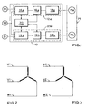
- an electric motor M which is presently embodied as a three-phase motor, provides an assisting torque for steering at least one wheel not shown in the figure, which adds to the steering torque applied to a steering handle ,
- the loading of the electric motor M takes place as a function of sensor signals which are measured by sensors S1 and S2.
- the sensor S1 measures this at the steering handle applied steering torque (torque), the sensor S2, the angular position of an electric motor not shown in the figure.
- the unit designated 10 may be formed as (control) device or be provided only in the form of a circuit arrangement.
- the electrical machine M has two separate winding groups Ma and Mb. Each winding group can be separately energized.
- the winding group Ma is energized by a unit 12a which energizes winding group Mb from a unit 12b.
- the sensor signals S1 and S2 are processed by a data processing device 14a, which outputs control signals to a so-called gate drive unit (GDU) 16a, which has the task of converting the control signals into control signals for transistors 18a.
- GDU gate drive unit
- the GDU 16a forms as a means for converting together with the associated transistors 18a power electronics.
- a data processing device 14b which receives the signals of the sensors S1 and S2, passes control signals to a gate drive unit 16b, which in turn drives transistors 18b. By appropriate switching of the transistors 18b then flows a corresponding current through the winding Mb of the electric motor.
- the GDU 16a forms as a means for converting together with the associated transistors 18b power electronics.
- the two data processing devices 14a and 14b are monitored by a monitoring computer 20 and synchronized in time, which can also turn off the GDUs 16a and 16b.
- the transistors 18a cause the current to flow in the corresponding phases via the lines U1, V1 and W1, which correspond in each case to one winding of the winding group Ma. These windings are combined in a star connection for the winding group Ma.
- the transistors 18b in the present case cause the flow of current in the corresponding phases via the lines U2, V2, W2, which each have a Winding of the winding group Mb corresponds. These windings are also coupled in a star connection and form the winding group Mb.
- the provision of the two winding groups Ma and Mb, which can be supplied with current by separate units 12a and 12b, has the advantage that if one of the two units 12a, 12b or a component of these units 12a, 12b fails, at least that of the failing Unit not belonging to winding group is still energized.
- the monitoring device 20 may cause the current intensity of the current caused by the respective unit 12a, 12b to be increased when the respective other unit 12b, 12a has failed.
- the sensors S1 and S2 are each provided in duplicate in order to provide redundancy in the area of the sensor, so that increased reliability is ensured.
Landscapes
- Engineering & Computer Science (AREA)
- Chemical & Material Sciences (AREA)
- Combustion & Propulsion (AREA)
- Transportation (AREA)
- Mechanical Engineering (AREA)
- Power Steering Mechanism (AREA)
- Control Of Ac Motors In General (AREA)
Description
- Die Erfindung betrifft ein Kraftfahrzeug mit einer Lenkhandhabe zum Lenken zumindest eines Rades und mit einer elektrischen Maschine zum Bereitstellen eines unterstützenden Drehmoments zum Lenken des zumindest einen Rades, wobei die elektrische Maschine zumindest zwei Wicklungsgruppen hat.
- Ein Kraftfahrzeug weist in an sich bekannter Weise eine Lenkhandhabe zum Lenken zumindest eines Rades auf, wobei an der Lenkhandhabe ein Lenkmoment aufgebracht wird. Eine Hilfskraftlenkung stellt zum Lenken dieses Rades ein unterstützendes Drehmoment bereit, welches zu dem Lenkmoment hinzutritt. Bei der elektrischen Hilfskraftlenkung wird das unterstützende Drehmoment von einer elektrischen Maschine aufgebracht.
- Die Ansteuerung der elektrischen Maschine erfolgt üblicherweise unter Einsatz elektronischer Komponenten. Elektronische Komponenten können abrupt ausfallen; in diesem Falle entfällt spontan das unterstützende Drehmoment, was für den Fahrzeugführer nicht angenehm ist.
- Eine gattungsgemäße elektrische Hilfskraftlenkung zeigt die
JP2003174790A US2004113575 A1 gezeigt. - Die
EP1511155 A1 beschreibt eine Steuerungseinrichtung, die aufgrund verschiedener eingehender Signale zwei voneinander unabhängige Wechselrichter Einheiten dazu veranlasst die Wicklungsgruppen mit Strom zu beaufschlagen und weist ebenfalls einen ähnlichen Aufbau auf. - Nachteilig ist, dass durch diesen Aufbau eine Redundanz nur im Bereich der Strombeaufschlagung der Wicklungsgruppen möglich ist.
- Es ist Aufgabe der Erfindung, die Ausfallsicherheit der Hilfskraftlenkung bei einem Kraftfahrzeug der eingangs genannten Gattung weiter zu erhöhen.
- Die Aufgabe wird durch ein Kraftfahrzeug mit den Merkmalen gemäß Patentanspruch 1 gelöst.
- Erfindungsgemäß erfolgt die Beaufschlagung mit elektrischem Strom der zwei an sich bekannten Wicklungsgruppen durch zumindest teilweise voneinander getrennte Einheiten wobei jeder Wicklungsgruppe eine gesonderte Datenverarbeitungseinrichtung zum Ermitteln des Umfangs der Beaufschlagung mit elektrischem Strom zugeordnet ist, und wobei diese gesonderten Datenverarbeitungseinrichtungen gemeinsam durch eine Überwachungseinrichtung überwacht werden.
- Jede der voneinander getrennten Einheiten, die eine zugehörige Wicklungsgruppe mit Strom beaufschlagen, umfasst eine gesonderte Datenverarbeitungseinrichtung zum Ermitteln des Umfangs der Beaufschlagung mit elektrischem Strom. Es besteht somit Redundanz sogar im Bereich von Datenverarbeitungseinrichtungen; selbst, wenn eine ganze Datenverarbeitungseinrichtung ausfällt, arbeitet die andere Datenverarbeitungseinrichtung noch weiter, sodass eine Wicklungsgruppe der elektrischen Maschine nach wie vor mit elektrischem Strom beaufschlagt wird und auch die Ermittlung des Umfangs der Beaufschlagung weiterhin gewährleistet ist. Die Trennung der beiden Einheiten voneinander besteht insbesondere im gesonderten Bereitstellen jeweils gleichartiger Bauteile. Man kann aber Synergieeffekte nutzen. So ist es bekannt, für die Datenverarbeitungseinrichtung eine weitere, typischerweise eine geringere Rechenleistung als die Datenverarbeitungseinrichtung aufweisende Überwachungseinrichtung vorzusehen, die die Datenverarbeitungseinrichtung überwacht. Vorliegend genügt es, für die Datenverarbeitungseinrichtung in beiden Einheiten gemeinsam lediglich eine Überwachungseinrichtung vorzusehen; es werden hierbei Kosten, Gewicht und Platz eingespart. Die Überwachungseinrichtung hat zudem die Aufgabe, die Ansteuerung beider Einrichtungen zeitlich zu synchronisieren.
- In einer bevorzugten Ausführungsform umfasst jede Einheit eine der Datenverarbeitungseinrichtung nachgeordnete Leistungselektronik, die aufgrund von Ausgangssignalen der Datenverarbeitungseinrichtung eine Beaufschlagung des Elektromotors mit Strom zu bewirken ausgelegt ist. Typischerweise wandelt die Leistungselektronik die von der Datenverarbeitungseinrichtung abgegebenen Steuersignale zunächst in Steuersignale für Transistoren in der Leistungselektronik um, und aufgrund dieser Steuersignale kommt es dann zum Fließen von elektrischem Strom über die Wicklungen des Elektromotors.
- Die Datenverarbeitungseinrichtungen sollen ja voneinander unabhängig arbeiten können. Es ist bevorzugt hierzu vorgesehen, dass jede Datenverarbeitungseinrichtung der beiden Einheiten mit denselben Sensoren gekoppelt ist. Typischerweise gibt es als Sensoren den Lenkmomentensensor, der das an der Lenkhandhabe aufgebrachte Lenkmoment misst, und es gibt einen Rotorlagesensor, der die Drehlage (Winkelstellung) eines Rotors der elektrischen Maschine erfasst, wobei auf diese Drehlage z. B. geregelt wird.
- Nachfolgend wird eine bevorzugte Ausführungsform der Erfindung unter Bezug auf die Zeichnung näher beschrieben, in der
- Fig. 1
- eine schematische Darstellung der Anordnung für eine Hilfskraftlenkung in einem erfindungsgemäßen Kraftfahrzeug ist und
- Fig. 2
- und
- Fig. 3
- die bei der Anordnung aus
Fig. 1 gegebenen Verschaltungen veranschaulichen. - In einem im Ganzen in den Figuren nicht gezeigten Kraftfahrzeug wird ein Elektromotor M, der vorliegend als Drei-Phasen-Motor ausgebildet ist, ein unterstützendes Drehmoment zum Lenken zumindest eines in der Figur nicht gezeigten Rades bereitgestellt, das zu dem an einer Lenkhandhabe aufgebrachten Lenkmoment hinzutritt. Die Beaufschlagung des Elektromotors M erfolgt in Abhängigkeit von Sensorsignalen, die durch Sensoren S1 und S2 gemessen werden. Der Sensor S1 misst hierbei das an der Lenkhandhabe aufgebrachte Lenkmoment (Drehmoment), der Sensor S2 die Winkelstellung eines in der Figur nicht gezeigten Elektromotors. Die mit 10 bezeichnete Einheit kann als (Steuer-)Gerät ausgebildet sein oder lediglich in Form einer Schaltungsanordnung bereitgestellt sein.
- Die elektrische Maschine M weist vorliegend zwei voneinander getrennte Wicklungsgruppen Ma und Mb auf. Jede Wicklungsgruppe kann gesondert mit Strom beaufschlagt werden. Die Wicklungsgruppe Ma wird von einer Einheit 12a mit Strom beaufschlagt, die Wicklungsgruppe Mb von einer Einheit 12b mit Strom beaufschlagt.
- In an sich bekannter Weise werden die Sensorsignale S1 und S2 von einer Datenverarbeitungseinrichtung 14a verarbeitet, die Steuersignale an eine sog. Gate Drive Unit (GDU) 16a abgibt, welche die Aufgabe des Umwandelns der Steuersignale in Steuersignale für Transistoren 18a hat. Durch geeignete Schaltung der Transistoren fließt dann ein entsprechender Strom über die Wicklung Ma des Elektromotors M. Die GDU 16a bildet als Einrichtung zum Wandeln gemeinsam mit den zugehörigen Transistoren 18a eine Leistungselektronik.
- Genauso gibt es eine Datenverarbeitungseinrichtung 14b, die die Signale der Sensoren S1 und S2 empfängt, Steuersignale an eine Gate Drive Unit 16b weitergibt, die wiederum Transistoren 18b ansteuert. Durch geeignete Schaltung der Transistoren 18b fließt dann ein entsprechender Strom über die Wicklung Mb des Elektromotors. Die GDU 16a bildet als Einrichtung zum Wandeln gemeinsam mit den zugehörigen Transistoren 18b eine Leistungselektronik.
- Die beiden Datenverarbeitungseinrichtungen 14a und 14b werden von einem Überwachungsrechner 20 überwacht und zeitlich synchronisiert, der auch die GDUs 16a und 16b abschalten kann.
- Die Transistoren 18a bewirken vorliegend das Fließen von Strom in den entsprechenden Phasen über die Leitungen U1, V1 und W1, denen jeweils eine Wicklung der Wicklungsgruppe Ma entspricht. Diese Wicklungen sind in einer Sternschaltung für die Wicklungsgruppe Ma zusammengeführt. Genauso bewirken die Transistoren 18b vorliegend das Fließen von Strom in den entsprechenden Phasen über die Leitungen U2, V2, W2, denen jeweils eine Wicklung der Wicklungsgruppe Mb entspricht. Auch diese Wicklungen sind in einer Sternschaltung verkoppelt und bilden die Wicklungsgruppe Mb.
- Das Vorsehen der beiden Wicklungsgruppen Ma und Mb, die durch jeweils gesonderte Einheiten 12a und 12b mit Strom beaufschlagt werden können, hat den Vorteil, dass bei Ausfall einer der beiden Einheiten 12a, 12b bzw. eines Bauteils dieser Einheiten 12a, 12b zumindest die der ausfallenden Einheit nicht zugehörige Wicklungsgruppe noch mit Strom beaufschlagt wird. Gegebenenfalls kann die Überwachungseinrichtung 20 sogar durch Übermittlung entsprechender Signale an die jeweilige Datenverarbeitungseinrichtung 14a, 14b bewirken, dass die Stromstärke des von der jeweiligen Einheit 12a, 12b zu fließen bewirkten Stroms erhöht wird, wenn die jeweils andere Einheit 12b, 12a ausgefallen ist.
- Anders als in den Figuren dargestellt, werden wie an sich bekannt und üblich die Sensoren S1 und S2 jeweils zweifach bereitgestellt, um auch im Bereich der Sensorik für eine Redundanz zu sorgen, damit eine erhöhte Ausfallsicherheit gegeben ist.
Claims (3)
- Kraftfahrzeug mit einer Lenkhandhabe zum Lenken zumindest eines Rades und mit einer elektrischen Maschine (M) zum Bereitstellen eines unterstützenden Drehmoments zum Lenken des zumindest einen Rades,
wobei
die elektrische Maschine (M) zumindest zwei Wicklungsgruppen (Ma, Mb) hat, deren Beaufschlagung mit elektrischem Strom durch zumindest teilweise voneinander getrennte Einheiten (12a, 12b) erfolgt, und dadurch gekennzeichnet, daß jeder Wicklungsgruppe (Ma, Mb) eine gesonderte Datenverarbeitungseinrichtung (14a, 14b) zum Ermitteln des Umfangs der Beaufschlagung mit elektrischem Strom zugeordnet ist, und wobei diese gesonderten Datenverarbeitungseinrichtungen (14a, 14b) gemeinsam durch eine Überwachungseinrichtung (20) überwacht werden. - Kraftfahrzeug nach Anspruch1 ,
dadurch gekennzeichnet, dass
jeder gesonderten Datenverarbeitungseinrichtung (14a, 14b) eine eigene Leistungselektronik (18a; 16b, 18b) nachgeordnet ist, die aufgrund von Ausgangssignalen der Datenverarbeitungseinrichtung eine Beaufschlagung der zugehörigen Wicklungsgruppe mit Strom zu bewirken ausgelegt ist. - Kraftfahrzeug nach Anspruch 1 oder 2,
dadurch gekennzeichnet, dass
jede gesonderte Datenverarbeitungseinrichtung (14a, 14b) mit den gleichen Sensoren (S1, S2) gekoppelt ist.
Applications Claiming Priority (1)
| Application Number | Priority Date | Filing Date | Title |
|---|---|---|---|
| DE201010050799 DE102010050799A1 (de) | 2010-11-09 | 2010-11-09 | Kraftfahrzeug mit elektrischer Hilfskraftlenkung |
Publications (2)
| Publication Number | Publication Date |
|---|---|
| EP2450259A1 EP2450259A1 (de) | 2012-05-09 |
| EP2450259B1 true EP2450259B1 (de) | 2013-09-25 |
Family
ID=45065577
Family Applications (1)
| Application Number | Title | Priority Date | Filing Date |
|---|---|---|---|
| EP20110008683 Active EP2450259B1 (de) | 2010-11-09 | 2011-10-29 | Kraftfahrzeug mit elektrischer Hilfskraftlenkung |
Country Status (2)
| Country | Link |
|---|---|
| EP (1) | EP2450259B1 (de) |
| DE (1) | DE102010050799A1 (de) |
Families Citing this family (45)
| Publication number | Priority date | Publication date | Assignee | Title |
|---|---|---|---|---|
| DE102010050818B4 (de) * | 2010-11-09 | 2021-07-01 | Volkswagen Ag | Kraftfahrzeug mit elektrischer Hilfskraftlenkung |
| US9812684B2 (en) | 2010-11-09 | 2017-11-07 | GM Global Technology Operations LLC | Using elastic averaging for alignment of battery stack, fuel cell stack, or other vehicle assembly |
| US9061403B2 (en) | 2011-07-21 | 2015-06-23 | GM Global Technology Operations LLC | Elastic tube alignment system for precisely locating an emblem lens to an outer bezel |
| JP2013071550A (ja) * | 2011-09-27 | 2013-04-22 | Jtekt Corp | 車両操舵装置の制御装置 |
| US9067379B2 (en) | 2012-04-28 | 2015-06-30 | GM Global Technologies Operations LLC | Stiffened multi-layer compartment door assembly utilizing elastic averaging |
| US9618026B2 (en) | 2012-08-06 | 2017-04-11 | GM Global Technology Operations LLC | Semi-circular alignment features of an elastic averaging alignment system |
| US9061715B2 (en) | 2012-08-09 | 2015-06-23 | GM Global Technology Operations LLC | Elastic cantilever beam alignment system for precisely aligning components |
| US9463538B2 (en) | 2012-08-13 | 2016-10-11 | GM Global Technology Operations LLC | Alignment system and method thereof |
| US9556890B2 (en) | 2013-01-31 | 2017-01-31 | GM Global Technology Operations LLC | Elastic alignment assembly for aligning mated components and method of reducing positional variation |
| US20140222292A1 (en) * | 2013-02-06 | 2014-08-07 | Steering Solutions Ip Holding Corporation | Vehicle electric power steering control system |
| US9828024B2 (en) | 2013-02-06 | 2017-11-28 | Steering Solutions Ip Holding Corporation | Power steering system |
| DE102013203978B4 (de) * | 2013-03-08 | 2025-02-20 | Bayerische Motoren Werke Aktiengesellschaft | Fahrzeug-Lenksystem |
| US9156506B2 (en) | 2013-03-27 | 2015-10-13 | GM Global Technology Operations LLC | Elastically averaged alignment system |
| US9278642B2 (en) | 2013-04-04 | 2016-03-08 | GM Global Technology Operations LLC | Elastically deformable flange locator arrangement and method of reducing positional variation |
| US9388838B2 (en) | 2013-04-04 | 2016-07-12 | GM Global Technology Operations LLC | Elastic retaining assembly for matable components and method of assembling |
| US9382935B2 (en) | 2013-04-04 | 2016-07-05 | GM Global Technology Operations LLC | Elastic tubular attachment assembly for mating components and method of mating components |
| US9297400B2 (en) | 2013-04-08 | 2016-03-29 | GM Global Technology Operations LLC | Elastic mating assembly and method of elastically assembling matable components |
| US9067625B2 (en) | 2013-04-09 | 2015-06-30 | GM Global Technology Operations LLC | Elastic retaining arrangement for jointed components and method of reducing a gap between jointed components |
| US9447840B2 (en) | 2013-06-11 | 2016-09-20 | GM Global Technology Operations LLC | Elastically deformable energy management assembly and method of managing energy absorption |
| US9243655B2 (en) | 2013-06-13 | 2016-01-26 | GM Global Technology Operations LLC | Elastic attachment assembly and method of reducing positional variation and increasing stiffness |
| US9488205B2 (en) | 2013-07-12 | 2016-11-08 | GM Global Technology Operations LLC | Alignment arrangement for mated components and method |
| US9303667B2 (en) | 2013-07-18 | 2016-04-05 | Gm Global Technology Operations, Llc | Lobular elastic tube alignment system for providing precise four-way alignment of components |
| US9863454B2 (en) | 2013-08-07 | 2018-01-09 | GM Global Technology Operations LLC | Alignment system for providing precise alignment and retention of components of a sealable compartment |
| US9458876B2 (en) | 2013-08-28 | 2016-10-04 | GM Global Technology Operations LLC | Elastically deformable alignment fastener and system |
| US9463831B2 (en) | 2013-09-09 | 2016-10-11 | GM Global Technology Operations LLC | Elastic tube alignment and fastening system for providing precise alignment and fastening of components |
| US9457845B2 (en) | 2013-10-02 | 2016-10-04 | GM Global Technology Operations LLC | Lobular elastic tube alignment and retention system for providing precise alignment of components |
| US9511802B2 (en) | 2013-10-03 | 2016-12-06 | GM Global Technology Operations LLC | Elastically averaged alignment systems and methods |
| US9669774B2 (en) | 2013-10-11 | 2017-06-06 | GM Global Technology Operations LLC | Reconfigurable vehicle interior assembly |
| US9481317B2 (en) | 2013-11-15 | 2016-11-01 | GM Global Technology Operations LLC | Elastically deformable clip and method |
| US9447806B2 (en) | 2013-12-12 | 2016-09-20 | GM Global Technology Operations LLC | Self-retaining alignment system for providing precise alignment and retention of components |
| US9428123B2 (en) | 2013-12-12 | 2016-08-30 | GM Global Technology Operations LLC | Alignment and retention system for a flexible assembly |
| US9216704B2 (en) | 2013-12-17 | 2015-12-22 | GM Global Technology Operations LLC | Elastically averaged strap systems and methods |
| US9599279B2 (en) | 2013-12-19 | 2017-03-21 | GM Global Technology Operations LLC | Elastically deformable module installation assembly |
| US9446722B2 (en) | 2013-12-19 | 2016-09-20 | GM Global Technology Operations LLC | Elastic averaging alignment member |
| US9238488B2 (en) | 2013-12-20 | 2016-01-19 | GM Global Technology Operations LLC | Elastically averaged alignment systems and methods |
| US9541113B2 (en) | 2014-01-09 | 2017-01-10 | GM Global Technology Operations LLC | Elastically averaged alignment systems and methods |
| US9463829B2 (en) | 2014-02-20 | 2016-10-11 | GM Global Technology Operations LLC | Elastically averaged alignment systems and methods |
| US9428046B2 (en) | 2014-04-02 | 2016-08-30 | GM Global Technology Operations LLC | Alignment and retention system for laterally slideably engageable mating components |
| US9429176B2 (en) | 2014-06-30 | 2016-08-30 | GM Global Technology Operations LLC | Elastically averaged alignment systems and methods |
| US9758110B2 (en) | 2015-01-12 | 2017-09-12 | GM Global Technology Operations LLC | Coupling system |
| DE102015217051A1 (de) * | 2015-09-07 | 2017-03-09 | Volkswagen Aktiengesellschaft | Nutzfahrzeuglenkung |
| JPWO2017115411A1 (ja) * | 2015-12-28 | 2018-03-22 | 三菱電機株式会社 | ステアバイワイヤ方式の電動パワーステアリング装置およびその制御方法 |
| JP6516792B2 (ja) * | 2017-06-22 | 2019-05-22 | 三菱電機株式会社 | 電動パワーステアリング装置を搭載した車両 |
| DE102017218271A1 (de) * | 2017-10-12 | 2019-04-18 | Bayerische Motoren Werke Aktiengesellschaft | Kontrollsystem für ein Kraftfahrzeug, Kraftfahrzeug, Verfahren zur Kontrolle eines Kraftfahrzeugs, Computerprogrammprodukt und computerlesbares Medium |
| JP7271943B2 (ja) * | 2018-12-25 | 2023-05-12 | 株式会社ジェイテクト | 操舵制御装置 |
Family Cites Families (8)
| Publication number | Priority date | Publication date | Assignee | Title |
|---|---|---|---|---|
| US4434389A (en) * | 1980-10-28 | 1984-02-28 | Kollmorgen Technologies Corporation | Motor with redundant windings |
| JP2002037112A (ja) * | 2000-07-25 | 2002-02-06 | Koyo Seiko Co Ltd | 車両用操舵装置 |
| DE10055160A1 (de) * | 2000-11-08 | 2002-05-23 | Bayerische Motoren Werke Ag | Fahrzeuglenksystem der Bauart "Steer-by-wire" |
| JP2003174790A (ja) * | 2001-12-05 | 2003-06-20 | Denso Corp | 車両用同期電動機装置 |
| JP3875188B2 (ja) * | 2002-12-16 | 2007-01-31 | 株式会社ジェイテクト | 電動モータ装置 |
| JP4492781B2 (ja) * | 2003-08-25 | 2010-06-30 | 株式会社ジェイテクト | 回転機及び操舵システム |
| DE102004051078B4 (de) * | 2004-10-20 | 2006-09-21 | Roland Arnold | Redundante Servomotoren für ein Gas-, Brems- und Lenksystem |
| JP4509841B2 (ja) * | 2005-03-29 | 2010-07-21 | 株式会社ショーワ | 電動パワーステアリング装置 |
-
2010
- 2010-11-09 DE DE201010050799 patent/DE102010050799A1/de not_active Withdrawn
-
2011
- 2011-10-29 EP EP20110008683 patent/EP2450259B1/de active Active
Also Published As
| Publication number | Publication date |
|---|---|
| EP2450259A1 (de) | 2012-05-09 |
| DE102010050799A1 (de) | 2012-05-10 |
Similar Documents
| Publication | Publication Date | Title |
|---|---|---|
| EP2450259A1 (de) | Kraftfahrzeug mit elektrischer Hilfskraftlenkung | |
| DE102015205627B4 (de) | Lastantriebsgerät | |
| DE112017001344T5 (de) | Motorsteuerungsvorrichtung | |
| DE112015005022T5 (de) | Motorantriebsvorrichtung und elektrische servolenkvorrichtung | |
| EP3083321B1 (de) | Vorrichtung und verfahren zum betreiben einer elektrischen maschine | |
| DE10053818B4 (de) | Elektrisches Lenksystem | |
| DE102015220043B4 (de) | Steuervorrichtung für eine drehende elektrische Maschine, und elektrische Servolenkungsvorrichtung, bei der diese verwendet wird | |
| DE102013103016A1 (de) | Motoransteuervorrichtung | |
| DE102012101006A1 (de) | Elektromechanische servolenkung geeignet für notlaufbetrieb | |
| DE102010037045A1 (de) | Betriebssteuervorrichtung | |
| DE102016114445B4 (de) | Dreiphasen-Wechselrichtersystem | |
| EP2608996B1 (de) | Sicherheitsschaltung für einen elektromotor einer elektromechanischen lenkung | |
| EP2331383B1 (de) | Vorrichtung und verfahren zur steuerung einer elektrischen lenkung | |
| EP2447104A1 (de) | Verfahren zur Steuerung einer elektrischen Drehfeldmaschine einer mobilen Arbeitsmaschine | |
| DE102021123899B4 (de) | Vorrichtung und verfahren zur steuerung des blockierens eines lenkrads | |
| DE102010050820B4 (de) | Vorrichtung zum Ansteuern eines Elektromotors für eine Hilfskraftlenkung | |
| DE112020003507T5 (de) | Lenkkraftunterstützungssystem und elektronische steuervorrichtung | |
| DE102010052441B4 (de) | Verfahren zum Betreiben einer elektrischen Hilfskraftlenkung sowie Kraftfahrzeug mit einer elektrischen Hilfskraftlenkung | |
| EP3732087B1 (de) | Lenkvorrichtung | |
| DE112017001097T5 (de) | Motoransteuervorrichtung | |
| EP2450258B1 (de) | Kraftfahrzeug mit elektrischer Hilfskraftlenkung | |
| EP3237261B1 (de) | Fahrzeug, insbesondere schienenfahrzeug, mit antriebssteuereinrichtung | |
| WO2023057192A1 (de) | Steuervorrichtung und verfahren zum betreiben eines elektromotors, insbesondere eines lenksystems | |
| DE102017211219A1 (de) | Verfahren und Vorrichtung zum Betreiben einer elektrischen Maschine, insbesondere eines Lenkunterstützungsantriebs | |
| EP2774266B1 (de) | Verfahren und vorrichtung zum betreiben einer elektronisch kommutierten elektrischen maschine in einem fehlerfall |
Legal Events
| Date | Code | Title | Description |
|---|---|---|---|
| PUAI | Public reference made under article 153(3) epc to a published international application that has entered the european phase |
Free format text: ORIGINAL CODE: 0009012 |
|
| AK | Designated contracting states |
Kind code of ref document: A1 Designated state(s): AL AT BE BG CH CY CZ DE DK EE ES FI FR GB GR HR HU IE IS IT LI LT LU LV MC MK MT NL NO PL PT RO RS SE SI SK SM TR |
|
| AX | Request for extension of the european patent |
Extension state: BA ME |
|
| RAP1 | Party data changed (applicant data changed or rights of an application transferred) |
Owner name: VOLKSWAGEN AKTIENGESELLSCHAFT Owner name: AUDI AG |
|
| 17P | Request for examination filed |
Effective date: 20121109 |
|
| RIC1 | Information provided on ipc code assigned before grant |
Ipc: B62D 5/04 20060101AFI20130130BHEP |
|
| GRAP | Despatch of communication of intention to grant a patent |
Free format text: ORIGINAL CODE: EPIDOSNIGR1 |
|
| INTG | Intention to grant announced |
Effective date: 20130625 |
|
| GRAS | Grant fee paid |
Free format text: ORIGINAL CODE: EPIDOSNIGR3 |
|
| GRAA | (expected) grant |
Free format text: ORIGINAL CODE: 0009210 |
|
| AK | Designated contracting states |
Kind code of ref document: B1 Designated state(s): AL AT BE BG CH CY CZ DE DK EE ES FI FR GB GR HR HU IE IS IT LI LT LU LV MC MK MT NL NO PL PT RO RS SE SI SK SM TR |
|
| REG | Reference to a national code |
Ref country code: GB Ref legal event code: FG4D Free format text: NOT ENGLISH |
|
| REG | Reference to a national code |
Ref country code: CH Ref legal event code: EP |
|
| REG | Reference to a national code |
Ref country code: AT Ref legal event code: REF Ref document number: 633586 Country of ref document: AT Kind code of ref document: T Effective date: 20131015 |
|
| REG | Reference to a national code |
Ref country code: IE Ref legal event code: FG4D Free format text: LANGUAGE OF EP DOCUMENT: GERMAN |
|
| REG | Reference to a national code |
Ref country code: DE Ref legal event code: R096 Ref document number: 502011001383 Country of ref document: DE Effective date: 20131121 |
|
| PG25 | Lapsed in a contracting state [announced via postgrant information from national office to epo] |
Ref country code: NO Free format text: LAPSE BECAUSE OF FAILURE TO SUBMIT A TRANSLATION OF THE DESCRIPTION OR TO PAY THE FEE WITHIN THE PRESCRIBED TIME-LIMIT Effective date: 20131225 Ref country code: LT Free format text: LAPSE BECAUSE OF FAILURE TO SUBMIT A TRANSLATION OF THE DESCRIPTION OR TO PAY THE FEE WITHIN THE PRESCRIBED TIME-LIMIT Effective date: 20130925 Ref country code: SE Free format text: LAPSE BECAUSE OF FAILURE TO SUBMIT A TRANSLATION OF THE DESCRIPTION OR TO PAY THE FEE WITHIN THE PRESCRIBED TIME-LIMIT Effective date: 20130925 Ref country code: HR Free format text: LAPSE BECAUSE OF FAILURE TO SUBMIT A TRANSLATION OF THE DESCRIPTION OR TO PAY THE FEE WITHIN THE PRESCRIBED TIME-LIMIT Effective date: 20130925 |
|
| REG | Reference to a national code |
Ref country code: NL Ref legal event code: VDEP Effective date: 20130925 |
|
| REG | Reference to a national code |
Ref country code: LT Ref legal event code: MG4D |
|
| PG25 | Lapsed in a contracting state [announced via postgrant information from national office to epo] |
Ref country code: GR Free format text: LAPSE BECAUSE OF FAILURE TO SUBMIT A TRANSLATION OF THE DESCRIPTION OR TO PAY THE FEE WITHIN THE PRESCRIBED TIME-LIMIT Effective date: 20131226 Ref country code: FI Free format text: LAPSE BECAUSE OF FAILURE TO SUBMIT A TRANSLATION OF THE DESCRIPTION OR TO PAY THE FEE WITHIN THE PRESCRIBED TIME-LIMIT Effective date: 20130925 Ref country code: LV Free format text: LAPSE BECAUSE OF FAILURE TO SUBMIT A TRANSLATION OF THE DESCRIPTION OR TO PAY THE FEE WITHIN THE PRESCRIBED TIME-LIMIT Effective date: 20130925 Ref country code: RS Free format text: LAPSE BECAUSE OF FAILURE TO SUBMIT A TRANSLATION OF THE DESCRIPTION OR TO PAY THE FEE WITHIN THE PRESCRIBED TIME-LIMIT Effective date: 20130925 Ref country code: SI Free format text: LAPSE BECAUSE OF FAILURE TO SUBMIT A TRANSLATION OF THE DESCRIPTION OR TO PAY THE FEE WITHIN THE PRESCRIBED TIME-LIMIT Effective date: 20130925 |
|
| BERE | Be: lapsed |
Owner name: VOLKSWAGEN A.G. Effective date: 20131031 Owner name: AUDI A.G. Effective date: 20131031 |
|
| PG25 | Lapsed in a contracting state [announced via postgrant information from national office to epo] |
Ref country code: SK Free format text: LAPSE BECAUSE OF FAILURE TO SUBMIT A TRANSLATION OF THE DESCRIPTION OR TO PAY THE FEE WITHIN THE PRESCRIBED TIME-LIMIT Effective date: 20130925 Ref country code: NL Free format text: LAPSE BECAUSE OF FAILURE TO SUBMIT A TRANSLATION OF THE DESCRIPTION OR TO PAY THE FEE WITHIN THE PRESCRIBED TIME-LIMIT Effective date: 20130925 Ref country code: EE Free format text: LAPSE BECAUSE OF FAILURE TO SUBMIT A TRANSLATION OF THE DESCRIPTION OR TO PAY THE FEE WITHIN THE PRESCRIBED TIME-LIMIT Effective date: 20130925 Ref country code: RO Free format text: LAPSE BECAUSE OF FAILURE TO SUBMIT A TRANSLATION OF THE DESCRIPTION OR TO PAY THE FEE WITHIN THE PRESCRIBED TIME-LIMIT Effective date: 20130925 Ref country code: CZ Free format text: LAPSE BECAUSE OF FAILURE TO SUBMIT A TRANSLATION OF THE DESCRIPTION OR TO PAY THE FEE WITHIN THE PRESCRIBED TIME-LIMIT Effective date: 20130925 Ref country code: IS Free format text: LAPSE BECAUSE OF FAILURE TO SUBMIT A TRANSLATION OF THE DESCRIPTION OR TO PAY THE FEE WITHIN THE PRESCRIBED TIME-LIMIT Effective date: 20140125 |
|
| PG25 | Lapsed in a contracting state [announced via postgrant information from national office to epo] |
Ref country code: PL Free format text: LAPSE BECAUSE OF FAILURE TO SUBMIT A TRANSLATION OF THE DESCRIPTION OR TO PAY THE FEE WITHIN THE PRESCRIBED TIME-LIMIT Effective date: 20130925 Ref country code: CY Free format text: LAPSE BECAUSE OF FAILURE TO SUBMIT A TRANSLATION OF THE DESCRIPTION OR TO PAY THE FEE WITHIN THE PRESCRIBED TIME-LIMIT Effective date: 20130925 Ref country code: ES Free format text: LAPSE BECAUSE OF FAILURE TO SUBMIT A TRANSLATION OF THE DESCRIPTION OR TO PAY THE FEE WITHIN THE PRESCRIBED TIME-LIMIT Effective date: 20130925 |
|
| REG | Reference to a national code |
Ref country code: DE Ref legal event code: R097 Ref document number: 502011001383 Country of ref document: DE |
|
| PG25 | Lapsed in a contracting state [announced via postgrant information from national office to epo] |
Ref country code: PT Free format text: LAPSE BECAUSE OF FAILURE TO SUBMIT A TRANSLATION OF THE DESCRIPTION OR TO PAY THE FEE WITHIN THE PRESCRIBED TIME-LIMIT Effective date: 20140127 Ref country code: MC Free format text: LAPSE BECAUSE OF FAILURE TO SUBMIT A TRANSLATION OF THE DESCRIPTION OR TO PAY THE FEE WITHIN THE PRESCRIBED TIME-LIMIT Effective date: 20130925 |
|
| REG | Reference to a national code |
Ref country code: IE Ref legal event code: MM4A |
|
| PLBE | No opposition filed within time limit |
Free format text: ORIGINAL CODE: 0009261 |
|
| STAA | Information on the status of an ep patent application or granted ep patent |
Free format text: STATUS: NO OPPOSITION FILED WITHIN TIME LIMIT |
|
| 26N | No opposition filed |
Effective date: 20140626 |
|
| PG25 | Lapsed in a contracting state [announced via postgrant information from national office to epo] |
Ref country code: DK Free format text: LAPSE BECAUSE OF FAILURE TO SUBMIT A TRANSLATION OF THE DESCRIPTION OR TO PAY THE FEE WITHIN THE PRESCRIBED TIME-LIMIT Effective date: 20130925 Ref country code: BE Free format text: LAPSE BECAUSE OF NON-PAYMENT OF DUE FEES Effective date: 20131031 |
|
| REG | Reference to a national code |
Ref country code: DE Ref legal event code: R097 Ref document number: 502011001383 Country of ref document: DE Effective date: 20140626 |
|
| PG25 | Lapsed in a contracting state [announced via postgrant information from national office to epo] |
Ref country code: IE Free format text: LAPSE BECAUSE OF NON-PAYMENT OF DUE FEES Effective date: 20131029 |
|
| PG25 | Lapsed in a contracting state [announced via postgrant information from national office to epo] |
Ref country code: SM Free format text: LAPSE BECAUSE OF FAILURE TO SUBMIT A TRANSLATION OF THE DESCRIPTION OR TO PAY THE FEE WITHIN THE PRESCRIBED TIME-LIMIT Effective date: 20130925 |
|
| REG | Reference to a national code |
Ref country code: CH Ref legal event code: PL |
|
| PG25 | Lapsed in a contracting state [announced via postgrant information from national office to epo] |
Ref country code: TR Free format text: LAPSE BECAUSE OF FAILURE TO SUBMIT A TRANSLATION OF THE DESCRIPTION OR TO PAY THE FEE WITHIN THE PRESCRIBED TIME-LIMIT Effective date: 20130925 |
|
| PG25 | Lapsed in a contracting state [announced via postgrant information from national office to epo] |
Ref country code: CH Free format text: LAPSE BECAUSE OF NON-PAYMENT OF DUE FEES Effective date: 20141031 Ref country code: LI Free format text: LAPSE BECAUSE OF NON-PAYMENT OF DUE FEES Effective date: 20141031 Ref country code: MK Free format text: LAPSE BECAUSE OF FAILURE TO SUBMIT A TRANSLATION OF THE DESCRIPTION OR TO PAY THE FEE WITHIN THE PRESCRIBED TIME-LIMIT Effective date: 20130925 Ref country code: LU Free format text: LAPSE BECAUSE OF NON-PAYMENT OF DUE FEES Effective date: 20131029 Ref country code: HU Free format text: LAPSE BECAUSE OF FAILURE TO SUBMIT A TRANSLATION OF THE DESCRIPTION OR TO PAY THE FEE WITHIN THE PRESCRIBED TIME-LIMIT; INVALID AB INITIO Effective date: 20111029 Ref country code: BG Free format text: LAPSE BECAUSE OF FAILURE TO SUBMIT A TRANSLATION OF THE DESCRIPTION OR TO PAY THE FEE WITHIN THE PRESCRIBED TIME-LIMIT Effective date: 20130925 |
|
| PG25 | Lapsed in a contracting state [announced via postgrant information from national office to epo] |
Ref country code: MT Free format text: LAPSE BECAUSE OF FAILURE TO SUBMIT A TRANSLATION OF THE DESCRIPTION OR TO PAY THE FEE WITHIN THE PRESCRIBED TIME-LIMIT Effective date: 20130925 |
|
| REG | Reference to a national code |
Ref country code: FR Ref legal event code: PLFP Year of fee payment: 5 |
|
| REG | Reference to a national code |
Ref country code: FR Ref legal event code: PLFP Year of fee payment: 6 |
|
| REG | Reference to a national code |
Ref country code: FR Ref legal event code: PLFP Year of fee payment: 7 |
|
| REG | Reference to a national code |
Ref country code: AT Ref legal event code: MM01 Ref document number: 633586 Country of ref document: AT Kind code of ref document: T Effective date: 20161029 |
|
| PG25 | Lapsed in a contracting state [announced via postgrant information from national office to epo] |
Ref country code: AT Free format text: LAPSE BECAUSE OF NON-PAYMENT OF DUE FEES Effective date: 20161029 |
|
| REG | Reference to a national code |
Ref country code: FR Ref legal event code: PLFP Year of fee payment: 8 |
|
| PG25 | Lapsed in a contracting state [announced via postgrant information from national office to epo] |
Ref country code: AL Free format text: LAPSE BECAUSE OF FAILURE TO SUBMIT A TRANSLATION OF THE DESCRIPTION OR TO PAY THE FEE WITHIN THE PRESCRIBED TIME-LIMIT Effective date: 20130925 |
|
| PGFP | Annual fee paid to national office [announced via postgrant information from national office to epo] |
Ref country code: FR Payment date: 20221021 Year of fee payment: 12 |
|
| PGFP | Annual fee paid to national office [announced via postgrant information from national office to epo] |
Ref country code: IT Payment date: 20221031 Year of fee payment: 12 |
|
| P01 | Opt-out of the competence of the unified patent court (upc) registered |
Effective date: 20230530 |
|
| REG | Reference to a national code |
Ref country code: DE Ref legal event code: R081 Ref document number: 502011001383 Country of ref document: DE Owner name: VOLKSWAGEN AG, DE Free format text: FORMER OWNERS: VOLKSWAGEN AG, 38440 WOLFSBURG, DE; AUDI AG, 85057 INGOLSTADT, DE |
|
| REG | Reference to a national code |
Ref country code: GB Ref legal event code: 732E Free format text: REGISTERED BETWEEN 20231130 AND 20231206 |
|
| PG25 | Lapsed in a contracting state [announced via postgrant information from national office to epo] |
Ref country code: FR Free format text: LAPSE BECAUSE OF NON-PAYMENT OF DUE FEES Effective date: 20231031 |
|
| PG25 | Lapsed in a contracting state [announced via postgrant information from national office to epo] |
Ref country code: IT Free format text: LAPSE BECAUSE OF NON-PAYMENT OF DUE FEES Effective date: 20231029 |
|
| PG25 | Lapsed in a contracting state [announced via postgrant information from national office to epo] |
Ref country code: IT Free format text: LAPSE BECAUSE OF NON-PAYMENT OF DUE FEES Effective date: 20231029 |
|
| REG | Reference to a national code |
Ref country code: DE Ref legal event code: R082 Ref document number: 502011001383 Country of ref document: DE |
|
| PGFP | Annual fee paid to national office [announced via postgrant information from national office to epo] |
Ref country code: DE Payment date: 20251031 Year of fee payment: 15 |
|
| PGFP | Annual fee paid to national office [announced via postgrant information from national office to epo] |
Ref country code: GB Payment date: 20251021 Year of fee payment: 15 |