EP2449945A2 - Appareil ménager doté d'une pompe à chaleur sur le circuit d'eau de traitement - Google Patents
Appareil ménager doté d'une pompe à chaleur sur le circuit d'eau de traitement Download PDFInfo
- Publication number
- EP2449945A2 EP2449945A2 EP12000566A EP12000566A EP2449945A2 EP 2449945 A2 EP2449945 A2 EP 2449945A2 EP 12000566 A EP12000566 A EP 12000566A EP 12000566 A EP12000566 A EP 12000566A EP 2449945 A2 EP2449945 A2 EP 2449945A2
- Authority
- EP
- European Patent Office
- Prior art keywords
- branch
- tub
- process water
- domestic appliance
- line
- Prior art date
- Legal status (The legal status is an assumption and is not a legal conclusion. Google has not performed a legal analysis and makes no representation as to the accuracy of the status listed.)
- Granted
Links
- XLYOFNOQVPJJNP-UHFFFAOYSA-N water Substances O XLYOFNOQVPJJNP-UHFFFAOYSA-N 0.000 title claims abstract description 60
- 238000000034 method Methods 0.000 title claims abstract description 45
- 230000008569 process Effects 0.000 title claims abstract description 45
- 239000007921 spray Substances 0.000 claims description 21
- 239000003990 capacitor Substances 0.000 claims description 10
- 239000000463 material Substances 0.000 claims 1
- 101150114468 TUB1 gene Proteins 0.000 description 10
- 230000008901 benefit Effects 0.000 description 7
- 238000010438 heat treatment Methods 0.000 description 4
- 239000000356 contaminant Substances 0.000 description 3
- 230000000694 effects Effects 0.000 description 2
- 238000005406 washing Methods 0.000 description 2
- 230000009471 action Effects 0.000 description 1
- 230000015572 biosynthetic process Effects 0.000 description 1
- 238000010276 construction Methods 0.000 description 1
- 238000011109 contamination Methods 0.000 description 1
- 230000008878 coupling Effects 0.000 description 1
- 238000010168 coupling process Methods 0.000 description 1
- 238000005859 coupling reaction Methods 0.000 description 1
- 230000001419 dependent effect Effects 0.000 description 1
- 238000005338 heat storage Methods 0.000 description 1
- 239000002245 particle Substances 0.000 description 1
- 230000009467 reduction Effects 0.000 description 1
- 230000000717 retained effect Effects 0.000 description 1
Images
Classifications
-
- A—HUMAN NECESSITIES
- A47—FURNITURE; DOMESTIC ARTICLES OR APPLIANCES; COFFEE MILLS; SPICE MILLS; SUCTION CLEANERS IN GENERAL
- A47L—DOMESTIC WASHING OR CLEANING; SUCTION CLEANERS IN GENERAL
- A47L15/00—Washing or rinsing machines for crockery or tableware
- A47L15/42—Details
- A47L15/4214—Water supply, recirculation or discharge arrangements; Devices therefor
- A47L15/4219—Water recirculation
-
- A—HUMAN NECESSITIES
- A47—FURNITURE; DOMESTIC ARTICLES OR APPLIANCES; COFFEE MILLS; SPICE MILLS; SUCTION CLEANERS IN GENERAL
- A47L—DOMESTIC WASHING OR CLEANING; SUCTION CLEANERS IN GENERAL
- A47L15/00—Washing or rinsing machines for crockery or tableware
- A47L15/42—Details
- A47L15/4202—Water filter means or strainers
-
- A—HUMAN NECESSITIES
- A47—FURNITURE; DOMESTIC ARTICLES OR APPLIANCES; COFFEE MILLS; SPICE MILLS; SUCTION CLEANERS IN GENERAL
- A47L—DOMESTIC WASHING OR CLEANING; SUCTION CLEANERS IN GENERAL
- A47L15/00—Washing or rinsing machines for crockery or tableware
- A47L15/42—Details
- A47L15/4214—Water supply, recirculation or discharge arrangements; Devices therefor
- A47L15/4219—Water recirculation
- A47L15/4221—Arrangements for redirection of washing water, e.g. water diverters to selectively supply the spray arms
-
- A—HUMAN NECESSITIES
- A47—FURNITURE; DOMESTIC ARTICLES OR APPLIANCES; COFFEE MILLS; SPICE MILLS; SUCTION CLEANERS IN GENERAL
- A47L—DOMESTIC WASHING OR CLEANING; SUCTION CLEANERS IN GENERAL
- A47L15/00—Washing or rinsing machines for crockery or tableware
- A47L15/42—Details
- A47L15/4285—Water-heater arrangements
-
- A—HUMAN NECESSITIES
- A47—FURNITURE; DOMESTIC ARTICLES OR APPLIANCES; COFFEE MILLS; SPICE MILLS; SUCTION CLEANERS IN GENERAL
- A47L—DOMESTIC WASHING OR CLEANING; SUCTION CLEANERS IN GENERAL
- A47L15/00—Washing or rinsing machines for crockery or tableware
- A47L15/42—Details
- A47L15/4291—Recovery arrangements, e.g. for the recovery of energy or water
-
- D—TEXTILES; PAPER
- D06—TREATMENT OF TEXTILES OR THE LIKE; LAUNDERING; FLEXIBLE MATERIALS NOT OTHERWISE PROVIDED FOR
- D06F—LAUNDERING, DRYING, IRONING, PRESSING OR FOLDING TEXTILE ARTICLES
- D06F39/00—Details of washing machines not specific to a single type of machines covered by groups D06F9/00 - D06F27/00
- D06F39/04—Heating arrangements
-
- D—TEXTILES; PAPER
- D06—TREATMENT OF TEXTILES OR THE LIKE; LAUNDERING; FLEXIBLE MATERIALS NOT OTHERWISE PROVIDED FOR
- D06F—LAUNDERING, DRYING, IRONING, PRESSING OR FOLDING TEXTILE ARTICLES
- D06F39/00—Details of washing machines not specific to a single type of machines covered by groups D06F9/00 - D06F27/00
- D06F39/08—Liquid supply or discharge arrangements
- D06F39/083—Liquid discharge or recirculation arrangements
-
- Y—GENERAL TAGGING OF NEW TECHNOLOGICAL DEVELOPMENTS; GENERAL TAGGING OF CROSS-SECTIONAL TECHNOLOGIES SPANNING OVER SEVERAL SECTIONS OF THE IPC; TECHNICAL SUBJECTS COVERED BY FORMER USPC CROSS-REFERENCE ART COLLECTIONS [XRACs] AND DIGESTS
- Y02—TECHNOLOGIES OR APPLICATIONS FOR MITIGATION OR ADAPTATION AGAINST CLIMATE CHANGE
- Y02B—CLIMATE CHANGE MITIGATION TECHNOLOGIES RELATED TO BUILDINGS, e.g. HOUSING, HOUSE APPLIANCES OR RELATED END-USER APPLICATIONS
- Y02B30/00—Energy efficient heating, ventilation or air conditioning [HVAC]
- Y02B30/52—Heat recovery pumps, i.e. heat pump based systems or units able to transfer the thermal energy from one area of the premises or part of the facilities to a different one, improving the overall efficiency
Definitions
- the invention relates to a water-conducting household appliance, in particular a dishwasher, with a tub for receiving to be cleaned Good and with a process water circuit comprising a circulation piping and a circulation pump to promote process water from a lower portion of the tub upwards.
- the household appliance is equipped with a heat pump comprising a condenser and an evaporator, wherein the condenser is configured to heat the process water.
- a device of this kind is eg off EP 2 215 954 known.
- the heat pump serves to improve the energy efficiency of the device.
- the condenser of the heat pump is disposed on the tub wall or between the sump of the tub and the circulation pump.
- the object is to improve the efficiency of such a device.
- the condenser is disposed on the circulation piping between the circulation pump and the tub.
- the device is designed so that (at least when the heat pump has to heat the process water) at least a portion of the process water on its way between the circulation pump and the tub can be brought into heat conductive contact with the condenser.
- the apparatus has a plurality of orifices (e.g., nozzles and other openings) through which the process water from the circulation piping system can be pumped into the tub.
- a branch is provided in the circulation piping, which is connected via a plurality of connecting lines with the orifices.
- the condenser can be placed between the branch and the orifices. This allows the flow of water through the condenser to be more easily optimized, e.g. by placing only a subset of the process water in thermal contact with the condenser or by placing the condenser on a connection line to a lower nozzle (which requires less pressure).
- This variant is particularly advantageous if a switching valve is arranged in the branch, with which the water can optionally be led to different mouths. This further enhances the flexibility to optimize heat input by selectively passing water through the condenser or not.
- a lower and an upper spray arm may be provided.
- the branch is connected to the lower spray arm via a lower connecting line and to the upper spray arm via an upper connecting line.
- the capacitor is advantageous with the lower Coupled connection line, since there the pressure reserve is the largest.
- the coupling may be direct (ie, the condenser is directly in heat-conducting contact with the lower connection line), or indirectly via a branch, ie, a portion of the water from the lower connection line is branched off and brought into heat-conducting contact with the condenser.
- a branch of this kind can be used independently of the presence of spray arms, etc.
- a branch is provided, which is arranged on the circulation line system and from which process water can flow into the tub via a connecting line as well as via a bypass line.
- the condenser is arranged on this bypass line.
- the said branch advantageously has a sieve. This is placed in such a way that process water flowing into the bypass line passes through the sieve, but not process water flowing into the connecting line. This prevents coarser contaminants from reaching the condenser and accumulating where they are difficult to remove. Rather, they are flushed into the connection line.
- the invention is particularly suitable for use in a dishwasher. However, it is conceivable, for example, also use in a washing machine.
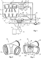
- Fig. 1 illustrates various embodiments of the invention on a dishwasher.
- This has a tub 1 for receiving the dishes.
- several orifices nozzles or other openings
- At least part of this is designed as nozzles so that the wash ware is treated with process water and that also dirt particles, which are located in the process water, can escape.
- These nozzles are from a ceiling nozzle 2, an upper spray arm. 3 and a lower spray arm 4 is formed.
- the spray arms 3, 4 are arranged in a known manner between two baskets or below the lower dish rack, the baskets in Fig. 1 are not shown.
- the tub 1 is closed laterally by walls 5 and down by a bottom portion 6, forming at a lowest point a sump 7, in which runs the process water.
- the process water is circulated in a process water cycle.
- This comprises a circulation pump 8, which conveys the process water via a circulation line system from the lower region of the tub 1, namely the sump 7, up to the mouths.
- the apparatus has a heat pump including a compressor 10, a condenser 11, an expansion valve (or a capillary) 12, and an evaporator 13.
- the heat pump is used to heat the process water.
- the condenser 11 is thermally coupled to the circulation piping between the circulation pump 8 and the tub 1 to heat the process water there.
- the evaporator 13 may e.g. be coupled with a latent heat storage (or other large thermal mass) and / or with the drainage system of the device to remove this heat.
- the circulation line system comprises a first connection line 15, via which the process water from the circulation pump 8 can be led to a branch 16.
- the branch 16 is then connected to the nozzles via a plurality of connecting lines 17-20.
- a switching valve 21 is provided in the branch 16 to guide the water over the various connecting lines 17-20 to the different mouths.
- the switching valve 21 may be configured so that the process water is supplied to only one connecting line, or even so that the process water can be fed to several connecting lines simultaneously. Corresponding arrangements are known to the person skilled in the art and need not be described in detail here.
- the condenser 11 may be disposed at the circulation system between the circulation pump 8 and the tub 1.
- Fig. 1 shows for this purpose different variants A, B, C, D, E, F, G, H, of which in practice preferably exactly one is selected. The different variants are described in more detail below.
- the condenser 11 is arranged on a bypass line 23, which in turn is connected at a first end to a branch 24 and at a second end in the bottom region 6 (or on the wall 5 or in the sump 7). the tub opens.
- the bypass line 23 can also be guided with its output on the suction side to the circulation pump 8.
- the corresponding orifice is to be understood as a "nozzle" within the meaning of the claims, even if it does not necessarily have to be designed so that it sprays the items to be washed.
- the branch 24 is arranged in the region of connecting line 17, which is referred to below as the "lower connecting line” and which connects the branch 16 to the lower spray arm 4.
- the branch 24 is designed such that the water coming from the branch 16 is divided into the bypass line 23 and into the lower connecting line 17.
- the running through the bypass line 23 water passes directly into the tub 1, while that through the lower connecting line 17 running water passes through the lower spray arm 4 and its nozzles in the tub 1.
- variant B the branch 24 and the bypass line 23 are dispensed with and the condenser 11 is arranged directly in thermal contact with the lower connecting line 17.
- This variant like variant A, has the advantage that a pressure drop generated by the condenser 11 only affects the lower spray arm 4, where the pressure is generally sufficiently high anyway.
- variant B also has the advantage of a simpler structure.
- it is prone to contamination, since the filter action of the branch 24 described below must be dispensed with.
- a permanently increased flow loss must be accepted and thus also an increased energy requirement.
- the condenser 11 is arranged on a special connecting line 18 which leads from the branch 16 to the wall 5 (or the bottom area 6 or the sump 7) of the tub 1 or on the suction side to the circulation pump 8.
- This variant has the advantage that the branch in which the condenser 11 is arranged can be switched on and off selectively by the reversing valve 21, so that outside the heating phase the condenser 11 can be completely switched off and the pressure loss caused by it is then eliminated.
- Disadvantage is the additional, due to the connection line 18 construction costs (connecting line 18 is not needed in the other variants).
- this solution can not use the filter effect of the branch 24 unless a corresponding filter arrangement is provided directly in the region of the branch.
- Another disadvantage is that during the heating phase, the spray system is not applied with full effect.
- Variants D and E correspond essentially to variants A and B, with the difference that the condenser 11 is coupled via a branch 24 or directly to the upper connecting line 19, which leads to the upper spray arm 3.
- the disadvantage of these variants compared to variants A and B is that the pressure loss associated with the operation of the condenser 11 hits the upper spray arm 3, where, compared to the lower spray arm 4, such pressure losses lead to a greater reduction in spray strength.
- the variants F and G correspond in turn substantially to the variants A and B, with the difference that the capacitor 11 is coupled via a branch 24 or directly to the connecting line 20, which leads to the ceiling nozzle 2. Even more so than in the variants D and E fall in these variants, however, the pressure losses generated by the condenser 1 disadvantageous. Another disadvantage is that during the heating phase, the crockery parts in the lower crockery basket are mechanically only weakly acted upon.
- the volume flow for the condenser 11 is removed before the branch 16 and guided into the bottom region 6 (or sump 7 or wall 5 or suction side to the circulation pump 8).
- a separate line 26 is provided which leads from a branch between the circulation pump 8 and the branch 16 directly to the tub or suction side to the circulation pump 8.
- a valve 25 is provided, with which the line can be closed.
- the capacitor 11 can be switched on or off at any time, regardless of the position of the switching valve 21 in the branch 16.
- this system requires the additional control valve 25.
- the filter described below may be provided in this case at the junction 24b.
- bypass lines 23 and branches 24 are according to Fig. 1 only required if the capacitor 11 is arranged in the respective bypass line 23. Otherwise they can be omitted.
- the bypass lines open, as far as they are needed, preferably in the wall 5, the bottom portion 6 or the sump 7 of the tub 1 or suction side to the circulation pump 8.
- the water flow through the bypass enters directly into the intake of the pump to the water circuit this Part as short as possible and thus to keep loss.
- the variants A, D, H and F each require the branch 24 or 24b.
- a particularly advantageous embodiment of this branch is described below.
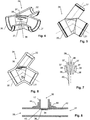
- This branch which in Fig. 2-6 is shown, serves to divert a portion of the water in the bypass line 23. It is preferably a purely passive component, ie there is no actuator available, with which the division ratio between branched and not branched water could be influenced.
- the branch 24 or 24b has an input 30, a first output 31 and a second output 32.
- the input 30 is connected via the connecting line 15 with the branch 16 and the switching valve 21 (or with the circulation pump in variant H).
- At the first output 31 connects the connecting line 17 (or 19, 20, 15 in the variants D, F and H) and at the second output 32, the bypass line 23 (or the line 26 in the variant H).
- the branch 24 forms a preferably angled pipeline 34 (FIG. Fig. 6 ).
- a sieve 36 is arranged, which covers the mouth of the second outlet 31 in the pipe 34.
- This embodiment has the advantage that no contaminants that could be prone to the formation of deposits can pass into the bypass line 23 and thus the heat exchanger to the condenser 11, where they would be difficult to remove. Rather, such contaminants are retained by the screen 36 and can be carried away by the process water through the first output 31. Therefore, it is advantageous if between the input 30 and the first output 31 no sieve is arranged.
- the sieve 36 a plurality of ribs 37, between which elongated sieve openings 38 are formed for the passage of the process water.
- the ribs 37 extend essentially parallel to the longitudinal axis 39 of the pipeline 34, ie in the projection onto the screen plane (FIG. Fig. 7 ), the angle 40 between the longitudinal axis 39 and the ribs 37 is preferably at most 30 °, in particular at most 15 °.
- the screen 36 is arranged substantially flush with the wall of the pipeline 34. This can also reduce the risk of sticking of dirt.
- the division ratio between branched and non-branched water can be adjusted by the relative flow resistance of the process water in its two paths.
- the flow resistances such that more process water flows through the connecting line 17 (or 19, 20) than through the bypass line 23. It turns out that this is sufficient for heating the process water.
- the division ratio between the process water flow in the connecting line 17 (or 19, 20) and the bypass line 23 is at least 2: 1, in particular about 3: 1.
- the flow through the connecting line 17 can be set to about 35 liters / minute and that through the bypass to about 10 liters / minute.
- the branch 24 is formed by a one-piece component, for example an injection-molded component.
- a one-piece component for example an injection-molded component.
- FIG. 8 An alternative solution is in Fig. 8 shown.
- the pipe 34 is formed by a hose 42 having a lateral opening 43.
- a connection piece 44 is welded or molded on the outside, in which the end of the bypass line 17 (or 19, 20) is held sealed.
- the mouth of the bypass line 17 is arranged in the region of the wall of the tube 42 and receives the screen 36.
- the invention has been illustrated with reference to a dishwasher. However, it can also be used in a washing machine, as far as it has a process water circuit with circulation piping and circulation pump.
- the use of the above-described branch 24 is also of particular advantage there.
Landscapes
- Engineering & Computer Science (AREA)
- Water Supply & Treatment (AREA)
- Washing And Drying Of Tableware (AREA)
- Domestic Hot-Water Supply Systems And Details Of Heating Systems (AREA)
Priority Applications (1)
| Application Number | Priority Date | Filing Date | Title |
|---|---|---|---|
| EP12000566.5A EP2449945B1 (fr) | 2012-01-30 | 2012-01-30 | Appareil ménager doté d'une pompe à chaleur sur le circuit d'eau de traitement |
Applications Claiming Priority (1)
| Application Number | Priority Date | Filing Date | Title |
|---|---|---|---|
| EP12000566.5A EP2449945B1 (fr) | 2012-01-30 | 2012-01-30 | Appareil ménager doté d'une pompe à chaleur sur le circuit d'eau de traitement |
Publications (3)
| Publication Number | Publication Date |
|---|---|
| EP2449945A2 true EP2449945A2 (fr) | 2012-05-09 |
| EP2449945A3 EP2449945A3 (fr) | 2012-08-29 |
| EP2449945B1 EP2449945B1 (fr) | 2020-07-29 |
Family
ID=45654785
Family Applications (1)
| Application Number | Title | Priority Date | Filing Date |
|---|---|---|---|
| EP12000566.5A Active EP2449945B1 (fr) | 2012-01-30 | 2012-01-30 | Appareil ménager doté d'une pompe à chaleur sur le circuit d'eau de traitement |
Country Status (1)
| Country | Link |
|---|---|
| EP (1) | EP2449945B1 (fr) |
Cited By (9)
| Publication number | Priority date | Publication date | Assignee | Title |
|---|---|---|---|---|
| EP2682040A1 (fr) * | 2012-07-03 | 2014-01-08 | Miele & Cie. KG | Lave-vaisselle et procédé de fonctionnement d'un lave-vaisselle |
| EP2682039A1 (fr) * | 2012-07-03 | 2014-01-08 | Miele & Cie. KG | Lave-vaisselle doté d'une pompe à chaleur |
| WO2015090409A1 (fr) * | 2013-12-19 | 2015-06-25 | Electrolux Appliances Aktiebolag | Lave-vaisselle comprenant un système de pompe à chaleur |
| CN106592179A (zh) * | 2015-10-16 | 2017-04-26 | 青岛海尔滚筒洗衣机有限公司 | 一种具有蒸汽功能的干衣机及蒸汽控制方法 |
| CN108024687A (zh) * | 2015-07-31 | 2018-05-11 | 伊利诺斯工具制品有限公司 | 具有热回收系统的器皿洗涤机 |
| US10058226B2 (en) | 2014-03-24 | 2018-08-28 | Electrolux Appliances Aktiebolag | Dishwasher comprising at least one dishwasher spray arm |
| WO2019049007A3 (fr) * | 2017-09-08 | 2019-05-02 | BSH Hausgeräte GmbH | Moyen pour empêcher l'encrassement d'un condenseur à plaques d'un lave-vaisselle ménager |
| WO2019132818A3 (fr) * | 2017-12-25 | 2019-08-22 | Arcelik Anonim Sirketi | Lave-vaisselle à pompe à chaleur ayant une performance améliorée de chauffage de l'eau de lavage |
| DE102013114273B4 (de) * | 2013-12-18 | 2019-11-14 | Miele & Cie. Kg | Geschirrspülmaschine |
Citations (1)
| Publication number | Priority date | Publication date | Assignee | Title |
|---|---|---|---|---|
| EP2215954A1 (fr) | 2009-02-09 | 2010-08-11 | V-Zug AG | Lave-vaisselle doté d'une pompe à chaleur |
Family Cites Families (5)
| Publication number | Priority date | Publication date | Assignee | Title |
|---|---|---|---|---|
| JP2007215887A (ja) * | 2006-02-20 | 2007-08-30 | Hitachi Appliances Inc | 食器洗浄機 |
| DE102007060196A1 (de) * | 2007-12-14 | 2009-06-18 | BSH Bosch und Siemens Hausgeräte GmbH | Geschirrspülmaschine |
| ITBO20080716A1 (it) * | 2008-11-28 | 2010-05-29 | Rivacold S R L | Dispositivo per la condensazione di vapore e per il recupero energetico |
| DE102009011571A1 (de) * | 2009-03-06 | 2010-09-09 | Aweco Appliance Systems Gmbh & Co. Kg | Haushaltsmaschine |
| PL2206824T3 (pl) * | 2010-02-16 | 2013-12-31 | V Zug Ag | Sprzęt gospodarstwa domowego ze zbiornikiem, pompą ciepła i pojemnikiem |
-
2012
- 2012-01-30 EP EP12000566.5A patent/EP2449945B1/fr active Active
Patent Citations (1)
| Publication number | Priority date | Publication date | Assignee | Title |
|---|---|---|---|---|
| EP2215954A1 (fr) | 2009-02-09 | 2010-08-11 | V-Zug AG | Lave-vaisselle doté d'une pompe à chaleur |
Cited By (17)
| Publication number | Priority date | Publication date | Assignee | Title |
|---|---|---|---|---|
| EP2682039A1 (fr) * | 2012-07-03 | 2014-01-08 | Miele & Cie. KG | Lave-vaisselle doté d'une pompe à chaleur |
| DE102012105907A1 (de) * | 2012-07-03 | 2014-01-09 | Miele & Cie. Kg | Geschirrspülmaschine und Verfahren zum Betreiben einer Geschirrspülmaschine |
| EP2682040A1 (fr) * | 2012-07-03 | 2014-01-08 | Miele & Cie. KG | Lave-vaisselle et procédé de fonctionnement d'un lave-vaisselle |
| DE102013114273B4 (de) * | 2013-12-18 | 2019-11-14 | Miele & Cie. Kg | Geschirrspülmaschine |
| WO2015090409A1 (fr) * | 2013-12-19 | 2015-06-25 | Electrolux Appliances Aktiebolag | Lave-vaisselle comprenant un système de pompe à chaleur |
| US10058226B2 (en) | 2014-03-24 | 2018-08-28 | Electrolux Appliances Aktiebolag | Dishwasher comprising at least one dishwasher spray arm |
| CN108024687B (zh) * | 2015-07-31 | 2021-06-04 | 伊利诺斯工具制品有限公司 | 具有热回收系统的器皿洗涤机 |
| CN108024687A (zh) * | 2015-07-31 | 2018-05-11 | 伊利诺斯工具制品有限公司 | 具有热回收系统的器皿洗涤机 |
| US10722097B2 (en) | 2015-07-31 | 2020-07-28 | Illinois Tool Works Inc. | Warewasher with heat recovery system |
| CN106592179B (zh) * | 2015-10-16 | 2020-09-08 | 青岛海尔滚筒洗衣机有限公司 | 一种具有蒸汽功能的干衣机及蒸汽控制方法 |
| CN106592179A (zh) * | 2015-10-16 | 2017-04-26 | 青岛海尔滚筒洗衣机有限公司 | 一种具有蒸汽功能的干衣机及蒸汽控制方法 |
| CN111050621A (zh) * | 2017-09-08 | 2020-04-21 | Bsh家用电器有限公司 | 用于防止家用洗碗机的板式冷凝器堵塞的机构 |
| WO2019049007A3 (fr) * | 2017-09-08 | 2019-05-02 | BSH Hausgeräte GmbH | Moyen pour empêcher l'encrassement d'un condenseur à plaques d'un lave-vaisselle ménager |
| US20210146407A1 (en) * | 2017-09-08 | 2021-05-20 | BSH Hausgeräte GmbH | Means for preventing the clogging of a plate condenser of a domestic dishwasher |
| US11548040B2 (en) * | 2017-09-08 | 2023-01-10 | BSH Hausgeräte GmbH | Means for preventing the clogging of a plate condenser of a domestic dishwasher |
| CN111050621B (zh) * | 2017-09-08 | 2023-03-21 | Bsh家用电器有限公司 | 用于防止家用洗碗机的板式冷凝器堵塞的机构 |
| WO2019132818A3 (fr) * | 2017-12-25 | 2019-08-22 | Arcelik Anonim Sirketi | Lave-vaisselle à pompe à chaleur ayant une performance améliorée de chauffage de l'eau de lavage |
Also Published As
| Publication number | Publication date |
|---|---|
| EP2449945B1 (fr) | 2020-07-29 |
| EP2449945A3 (fr) | 2012-08-29 |
Similar Documents
| Publication | Publication Date | Title |
|---|---|---|
| EP2449945B1 (fr) | Appareil ménager doté d'une pompe à chaleur sur le circuit d'eau de traitement | |
| DE102005062480B4 (de) | Geschirrspülmaschine | |
| DE102005008987B3 (de) | Mehrtankgeschirrspülmaschine mit Rückspülvorrichtung | |
| DE102008037344B4 (de) | Transportspülmaschine und Verfahren zum Betreiben einer Transportspülmaschine | |
| DE102006061211A1 (de) | Verfahren zum Entfernen von Flusen aus einem Wärmetauscher eines Hausgeräts, sowie entsprechendes Hausgerät | |
| EP0838190A2 (fr) | Machine à laver la vaisselle type tunnel et procédé pour nettoyer la vaisselle et/ou les plateaux | |
| EP3254596B1 (fr) | Aiguillage d'eau et appareil ménager en étant équipé | |
| DE102007009252A1 (de) | Verfahren zum Betrieb einer Durchlaufgeschirrspülmaschine | |
| DE102013217468A1 (de) | Verteilen einer Flüssigkeit in einem Haushaltsgerät | |
| DE4116228A1 (de) | Insbesondere fuer kleinteile ausgelegte geschirrspuelmaschine | |
| WO2012139772A1 (fr) | Machine à laver à transporteur possédant une zone de traitement spéciale | |
| EP2511413B1 (fr) | Appareil ménager doté d'un réservoir d'eau et d'un guidage du condensat | |
| EP3041983B1 (fr) | Appareil ménager avec vanne multi-voies | |
| DE102011077083A1 (de) | Geschirrspülmaschine, insbesondere Haushaltsgeschirrspülmaschine | |
| DE102008020922A1 (de) | Geschirrspülmaschine | |
| EP2682040B1 (fr) | Procédé de fonctionnement d'un lave-vaisselle | |
| EP3545813A1 (fr) | Lave-vaisselle, en particulier lave-vaisselle électroménager | |
| DE102008055817A1 (de) | Geschirrspülmaschine mit verbessertem Spüleffekt | |
| EP2905087B1 (fr) | Appareil de lavage | |
| DE102005030720A1 (de) | Transportgeschirrspülmaschine und Betriebsverfahren hierfür | |
| WO2010081638A2 (fr) | Lave-vaisselle | |
| EP3146883A1 (fr) | Lave-vaisselle, notamment lave-vaisselle ménager | |
| EP2116168A1 (fr) | Dispositif de séparation d'impuretés doté d'un réglage de niveau | |
| DE102009042866B4 (de) | Geschirrspülmaschine und Verfahren zum Spülen von Geschirr | |
| DE102008045783B4 (de) | Düsenvorrichtung eines Geschirrspülers |
Legal Events
| Date | Code | Title | Description |
|---|---|---|---|
| PUAI | Public reference made under article 153(3) epc to a published international application that has entered the european phase |
Free format text: ORIGINAL CODE: 0009012 |
|
| AK | Designated contracting states |
Kind code of ref document: A2 Designated state(s): AL AT BE BG CH CY CZ DE DK EE ES FI FR GB GR HR HU IE IS IT LI LT LU LV MC MK MT NL NO PL PT RO RS SE SI SK SM TR |
|
| AX | Request for extension of the european patent |
Extension state: BA ME |
|
| PUAL | Search report despatched |
Free format text: ORIGINAL CODE: 0009013 |
|
| AK | Designated contracting states |
Kind code of ref document: A3 Designated state(s): AL AT BE BG CH CY CZ DE DK EE ES FI FR GB GR HR HU IE IS IT LI LT LU LV MC MK MT NL NO PL PT RO RS SE SI SK SM TR |
|
| AX | Request for extension of the european patent |
Extension state: BA ME |
|
| RIC1 | Information provided on ipc code assigned before grant |
Ipc: A47L 15/42 20060101AFI20120725BHEP Ipc: A47L 15/48 20060101ALI20120725BHEP Ipc: D06F 39/00 20060101ALI20120725BHEP |
|
| 17P | Request for examination filed |
Effective date: 20130213 |
|
| RAP1 | Party data changed (applicant data changed or rights of an application transferred) |
Owner name: V-ZUG AG |
|
| GRAP | Despatch of communication of intention to grant a patent |
Free format text: ORIGINAL CODE: EPIDOSNIGR1 |
|
| STAA | Information on the status of an ep patent application or granted ep patent |
Free format text: STATUS: GRANT OF PATENT IS INTENDED |
|
| INTG | Intention to grant announced |
Effective date: 20200504 |
|
| GRAS | Grant fee paid |
Free format text: ORIGINAL CODE: EPIDOSNIGR3 |
|
| GRAA | (expected) grant |
Free format text: ORIGINAL CODE: 0009210 |
|
| STAA | Information on the status of an ep patent application or granted ep patent |
Free format text: STATUS: THE PATENT HAS BEEN GRANTED |
|
| AK | Designated contracting states |
Kind code of ref document: B1 Designated state(s): AL AT BE BG CH CY CZ DE DK EE ES FI FR GB GR HR HU IE IS IT LI LT LU LV MC MK MT NL NO PL PT RO RS SE SI SK SM TR |
|
| REG | Reference to a national code |
Ref country code: GB Ref legal event code: FG4D Free format text: NOT ENGLISH |
|
| REG | Reference to a national code |
Ref country code: CH Ref legal event code: NV Representative=s name: E. BLUM AND CO. AG PATENT- UND MARKENANWAELTE , CH Ref country code: CH Ref legal event code: EP |
|
| REG | Reference to a national code |
Ref country code: DE Ref legal event code: R096 Ref document number: 502012016238 Country of ref document: DE |
|
| REG | Reference to a national code |
Ref country code: AT Ref legal event code: REF Ref document number: 1294828 Country of ref document: AT Kind code of ref document: T Effective date: 20200815 |
|
| REG | Reference to a national code |
Ref country code: IE Ref legal event code: FG4D Free format text: LANGUAGE OF EP DOCUMENT: GERMAN |
|
| REG | Reference to a national code |
Ref country code: LT Ref legal event code: MG4D |
|
| REG | Reference to a national code |
Ref country code: NL Ref legal event code: MP Effective date: 20200729 |
|
| PG25 | Lapsed in a contracting state [announced via postgrant information from national office to epo] |
Ref country code: NO Free format text: LAPSE BECAUSE OF FAILURE TO SUBMIT A TRANSLATION OF THE DESCRIPTION OR TO PAY THE FEE WITHIN THE PRESCRIBED TIME-LIMIT Effective date: 20201029 Ref country code: FI Free format text: LAPSE BECAUSE OF FAILURE TO SUBMIT A TRANSLATION OF THE DESCRIPTION OR TO PAY THE FEE WITHIN THE PRESCRIBED TIME-LIMIT Effective date: 20200729 Ref country code: PT Free format text: LAPSE BECAUSE OF FAILURE TO SUBMIT A TRANSLATION OF THE DESCRIPTION OR TO PAY THE FEE WITHIN THE PRESCRIBED TIME-LIMIT Effective date: 20201130 Ref country code: HR Free format text: LAPSE BECAUSE OF FAILURE TO SUBMIT A TRANSLATION OF THE DESCRIPTION OR TO PAY THE FEE WITHIN THE PRESCRIBED TIME-LIMIT Effective date: 20200729 Ref country code: ES Free format text: LAPSE BECAUSE OF FAILURE TO SUBMIT A TRANSLATION OF THE DESCRIPTION OR TO PAY THE FEE WITHIN THE PRESCRIBED TIME-LIMIT Effective date: 20200729 Ref country code: GR Free format text: LAPSE BECAUSE OF FAILURE TO SUBMIT A TRANSLATION OF THE DESCRIPTION OR TO PAY THE FEE WITHIN THE PRESCRIBED TIME-LIMIT Effective date: 20201030 Ref country code: LT Free format text: LAPSE BECAUSE OF FAILURE TO SUBMIT A TRANSLATION OF THE DESCRIPTION OR TO PAY THE FEE WITHIN THE PRESCRIBED TIME-LIMIT Effective date: 20200729 Ref country code: BG Free format text: LAPSE BECAUSE OF FAILURE TO SUBMIT A TRANSLATION OF THE DESCRIPTION OR TO PAY THE FEE WITHIN THE PRESCRIBED TIME-LIMIT Effective date: 20201029 Ref country code: SE Free format text: LAPSE BECAUSE OF FAILURE TO SUBMIT A TRANSLATION OF THE DESCRIPTION OR TO PAY THE FEE WITHIN THE PRESCRIBED TIME-LIMIT Effective date: 20200729 |
|
| PG25 | Lapsed in a contracting state [announced via postgrant information from national office to epo] |
Ref country code: IS Free format text: LAPSE BECAUSE OF FAILURE TO SUBMIT A TRANSLATION OF THE DESCRIPTION OR TO PAY THE FEE WITHIN THE PRESCRIBED TIME-LIMIT Effective date: 20201129 Ref country code: LV Free format text: LAPSE BECAUSE OF FAILURE TO SUBMIT A TRANSLATION OF THE DESCRIPTION OR TO PAY THE FEE WITHIN THE PRESCRIBED TIME-LIMIT Effective date: 20200729 Ref country code: PL Free format text: LAPSE BECAUSE OF FAILURE TO SUBMIT A TRANSLATION OF THE DESCRIPTION OR TO PAY THE FEE WITHIN THE PRESCRIBED TIME-LIMIT Effective date: 20200729 Ref country code: RS Free format text: LAPSE BECAUSE OF FAILURE TO SUBMIT A TRANSLATION OF THE DESCRIPTION OR TO PAY THE FEE WITHIN THE PRESCRIBED TIME-LIMIT Effective date: 20200729 |
|
| PG25 | Lapsed in a contracting state [announced via postgrant information from national office to epo] |
Ref country code: NL Free format text: LAPSE BECAUSE OF FAILURE TO SUBMIT A TRANSLATION OF THE DESCRIPTION OR TO PAY THE FEE WITHIN THE PRESCRIBED TIME-LIMIT Effective date: 20200729 |
|
| PG25 | Lapsed in a contracting state [announced via postgrant information from national office to epo] |
Ref country code: SM Free format text: LAPSE BECAUSE OF FAILURE TO SUBMIT A TRANSLATION OF THE DESCRIPTION OR TO PAY THE FEE WITHIN THE PRESCRIBED TIME-LIMIT Effective date: 20200729 Ref country code: RO Free format text: LAPSE BECAUSE OF FAILURE TO SUBMIT A TRANSLATION OF THE DESCRIPTION OR TO PAY THE FEE WITHIN THE PRESCRIBED TIME-LIMIT Effective date: 20200729 Ref country code: IT Free format text: LAPSE BECAUSE OF FAILURE TO SUBMIT A TRANSLATION OF THE DESCRIPTION OR TO PAY THE FEE WITHIN THE PRESCRIBED TIME-LIMIT Effective date: 20200729 Ref country code: EE Free format text: LAPSE BECAUSE OF FAILURE TO SUBMIT A TRANSLATION OF THE DESCRIPTION OR TO PAY THE FEE WITHIN THE PRESCRIBED TIME-LIMIT Effective date: 20200729 Ref country code: CZ Free format text: LAPSE BECAUSE OF FAILURE TO SUBMIT A TRANSLATION OF THE DESCRIPTION OR TO PAY THE FEE WITHIN THE PRESCRIBED TIME-LIMIT Effective date: 20200729 Ref country code: DK Free format text: LAPSE BECAUSE OF FAILURE TO SUBMIT A TRANSLATION OF THE DESCRIPTION OR TO PAY THE FEE WITHIN THE PRESCRIBED TIME-LIMIT Effective date: 20200729 |
|
| REG | Reference to a national code |
Ref country code: DE Ref legal event code: R097 Ref document number: 502012016238 Country of ref document: DE |
|
| PG25 | Lapsed in a contracting state [announced via postgrant information from national office to epo] |
Ref country code: AL Free format text: LAPSE BECAUSE OF FAILURE TO SUBMIT A TRANSLATION OF THE DESCRIPTION OR TO PAY THE FEE WITHIN THE PRESCRIBED TIME-LIMIT Effective date: 20200729 |
|
| PLBE | No opposition filed within time limit |
Free format text: ORIGINAL CODE: 0009261 |
|
| STAA | Information on the status of an ep patent application or granted ep patent |
Free format text: STATUS: NO OPPOSITION FILED WITHIN TIME LIMIT |
|
| PG25 | Lapsed in a contracting state [announced via postgrant information from national office to epo] |
Ref country code: SK Free format text: LAPSE BECAUSE OF FAILURE TO SUBMIT A TRANSLATION OF THE DESCRIPTION OR TO PAY THE FEE WITHIN THE PRESCRIBED TIME-LIMIT Effective date: 20200729 |
|
| 26N | No opposition filed |
Effective date: 20210430 |
|
| PG25 | Lapsed in a contracting state [announced via postgrant information from national office to epo] |
Ref country code: SI Free format text: LAPSE BECAUSE OF FAILURE TO SUBMIT A TRANSLATION OF THE DESCRIPTION OR TO PAY THE FEE WITHIN THE PRESCRIBED TIME-LIMIT Effective date: 20200729 Ref country code: MC Free format text: LAPSE BECAUSE OF FAILURE TO SUBMIT A TRANSLATION OF THE DESCRIPTION OR TO PAY THE FEE WITHIN THE PRESCRIBED TIME-LIMIT Effective date: 20200729 |
|
| GBPC | Gb: european patent ceased through non-payment of renewal fee |
Effective date: 20210130 |
|
| PG25 | Lapsed in a contracting state [announced via postgrant information from national office to epo] |
Ref country code: LU Free format text: LAPSE BECAUSE OF NON-PAYMENT OF DUE FEES Effective date: 20210130 |
|
| REG | Reference to a national code |
Ref country code: BE Ref legal event code: MM Effective date: 20210131 |
|
| PG25 | Lapsed in a contracting state [announced via postgrant information from national office to epo] |
Ref country code: FR Free format text: LAPSE BECAUSE OF NON-PAYMENT OF DUE FEES Effective date: 20210131 |
|
| PG25 | Lapsed in a contracting state [announced via postgrant information from national office to epo] |
Ref country code: GB Free format text: LAPSE BECAUSE OF NON-PAYMENT OF DUE FEES Effective date: 20210130 |
|
| PG25 | Lapsed in a contracting state [announced via postgrant information from national office to epo] |
Ref country code: IE Free format text: LAPSE BECAUSE OF NON-PAYMENT OF DUE FEES Effective date: 20210130 |
|
| REG | Reference to a national code |
Ref country code: AT Ref legal event code: MM01 Ref document number: 1294828 Country of ref document: AT Kind code of ref document: T Effective date: 20210130 |
|
| PG25 | Lapsed in a contracting state [announced via postgrant information from national office to epo] |
Ref country code: AT Free format text: LAPSE BECAUSE OF NON-PAYMENT OF DUE FEES Effective date: 20210130 |
|
| PG25 | Lapsed in a contracting state [announced via postgrant information from national office to epo] |
Ref country code: IS Free format text: LAPSE BECAUSE OF FAILURE TO SUBMIT A TRANSLATION OF THE DESCRIPTION OR TO PAY THE FEE WITHIN THE PRESCRIBED TIME-LIMIT Effective date: 20201129 |
|
| PG25 | Lapsed in a contracting state [announced via postgrant information from national office to epo] |
Ref country code: BE Free format text: LAPSE BECAUSE OF NON-PAYMENT OF DUE FEES Effective date: 20210131 |
|
| PG25 | Lapsed in a contracting state [announced via postgrant information from national office to epo] |
Ref country code: HU Free format text: LAPSE BECAUSE OF FAILURE TO SUBMIT A TRANSLATION OF THE DESCRIPTION OR TO PAY THE FEE WITHIN THE PRESCRIBED TIME-LIMIT; INVALID AB INITIO Effective date: 20120130 Ref country code: CY Free format text: LAPSE BECAUSE OF FAILURE TO SUBMIT A TRANSLATION OF THE DESCRIPTION OR TO PAY THE FEE WITHIN THE PRESCRIBED TIME-LIMIT Effective date: 20200729 |
|
| P01 | Opt-out of the competence of the unified patent court (upc) registered |
Effective date: 20230425 |
|
| PG25 | Lapsed in a contracting state [announced via postgrant information from national office to epo] |
Ref country code: MK Free format text: LAPSE BECAUSE OF FAILURE TO SUBMIT A TRANSLATION OF THE DESCRIPTION OR TO PAY THE FEE WITHIN THE PRESCRIBED TIME-LIMIT Effective date: 20200729 |
|
| PGFP | Annual fee paid to national office [announced via postgrant information from national office to epo] |
Ref country code: DE Payment date: 20240119 Year of fee payment: 13 Ref country code: CH Payment date: 20240202 Year of fee payment: 13 |