EP2449862B1 - Düse für einen flüssigkeitsgekühlten plasmabrenner sowie plasmabrennerkopf mit derselben - Google Patents
Düse für einen flüssigkeitsgekühlten plasmabrenner sowie plasmabrennerkopf mit derselben Download PDFInfo
- Publication number
- EP2449862B1 EP2449862B1 EP10732275.2A EP10732275A EP2449862B1 EP 2449862 B1 EP2449862 B1 EP 2449862B1 EP 10732275 A EP10732275 A EP 10732275A EP 2449862 B1 EP2449862 B1 EP 2449862B1
- Authority
- EP
- European Patent Office
- Prior art keywords
- nozzle
- grooves
- liquid
- section
- plasma torch
- Prior art date
- Legal status (The legal status is an assumption and is not a legal conclusion. Google has not performed a legal analysis and makes no representation as to the accuracy of the status listed.)
- Active
Links
- 239000007788 liquid Substances 0.000 claims description 64
- 239000000110 cooling liquid Substances 0.000 claims description 39
- 239000002826 coolant Substances 0.000 description 45
- 239000007789 gas Substances 0.000 description 20
- XLYOFNOQVPJJNP-UHFFFAOYSA-N water Substances O XLYOFNOQVPJJNP-UHFFFAOYSA-N 0.000 description 14
- 238000001816 cooling Methods 0.000 description 12
- 238000005520 cutting process Methods 0.000 description 11
- 240000006829 Ficus sundaica Species 0.000 description 5
- 239000012530 fluid Substances 0.000 description 5
- 239000000463 material Substances 0.000 description 5
- 238000013021 overheating Methods 0.000 description 4
- RYGMFSIKBFXOCR-UHFFFAOYSA-N Copper Chemical compound [Cu] RYGMFSIKBFXOCR-UHFFFAOYSA-N 0.000 description 3
- 239000003570 air Substances 0.000 description 3
- QVGXLLKOCUKJST-UHFFFAOYSA-N atomic oxygen Chemical compound [O] QVGXLLKOCUKJST-UHFFFAOYSA-N 0.000 description 3
- 239000004020 conductor Substances 0.000 description 3
- 229910052802 copper Inorganic materials 0.000 description 3
- 239000010949 copper Substances 0.000 description 3
- 238000013461 design Methods 0.000 description 3
- 238000002845 discoloration Methods 0.000 description 3
- 239000001301 oxygen Substances 0.000 description 3
- 229910052760 oxygen Inorganic materials 0.000 description 3
- 230000007704 transition Effects 0.000 description 3
- 238000003466 welding Methods 0.000 description 3
- XKRFYHLGVUSROY-UHFFFAOYSA-N Argon Chemical compound [Ar] XKRFYHLGVUSROY-UHFFFAOYSA-N 0.000 description 2
- IJGRMHOSHXDMSA-UHFFFAOYSA-N Atomic nitrogen Chemical compound N#N IJGRMHOSHXDMSA-UHFFFAOYSA-N 0.000 description 2
- 229910001369 Brass Inorganic materials 0.000 description 2
- 239000010951 brass Substances 0.000 description 2
- 230000007797 corrosion Effects 0.000 description 2
- 238000005260 corrosion Methods 0.000 description 2
- 239000001257 hydrogen Substances 0.000 description 2
- 229910052739 hydrogen Inorganic materials 0.000 description 2
- 230000001590 oxidative effect Effects 0.000 description 2
- 238000007789 sealing Methods 0.000 description 2
- 230000008646 thermal stress Effects 0.000 description 2
- 230000001154 acute effect Effects 0.000 description 1
- 230000002528 anti-freeze Effects 0.000 description 1
- 229910052786 argon Inorganic materials 0.000 description 1
- 125000004429 atom Chemical group 0.000 description 1
- 238000004891 communication Methods 0.000 description 1
- 230000000694 effects Effects 0.000 description 1
- 238000002474 experimental method Methods 0.000 description 1
- 229910052735 hafnium Inorganic materials 0.000 description 1
- VBJZVLUMGGDVMO-UHFFFAOYSA-N hafnium atom Chemical compound [Hf] VBJZVLUMGGDVMO-UHFFFAOYSA-N 0.000 description 1
- 125000004435 hydrogen atom Chemical class [H]* 0.000 description 1
- 238000011835 investigation Methods 0.000 description 1
- 150000002500 ions Chemical class 0.000 description 1
- 238000004519 manufacturing process Methods 0.000 description 1
- 238000002844 melting Methods 0.000 description 1
- 230000008018 melting Effects 0.000 description 1
- 239000007769 metal material Substances 0.000 description 1
- 239000000203 mixture Substances 0.000 description 1
- 230000007935 neutral effect Effects 0.000 description 1
- 229910052757 nitrogen Inorganic materials 0.000 description 1
- 239000012811 non-conductive material Substances 0.000 description 1
- 238000007750 plasma spraying Methods 0.000 description 1
- 238000002360 preparation method Methods 0.000 description 1
- 229910052709 silver Inorganic materials 0.000 description 1
- 239000004332 silver Substances 0.000 description 1
- 239000007787 solid Substances 0.000 description 1
- WFKWXMTUELFFGS-UHFFFAOYSA-N tungsten Chemical compound [W] WFKWXMTUELFFGS-UHFFFAOYSA-N 0.000 description 1
- 229910052721 tungsten Inorganic materials 0.000 description 1
- 239000010937 tungsten Substances 0.000 description 1
Images


Classifications
-
- B—PERFORMING OPERATIONS; TRANSPORTING
- B23—MACHINE TOOLS; METAL-WORKING NOT OTHERWISE PROVIDED FOR
- B23K—SOLDERING OR UNSOLDERING; WELDING; CLADDING OR PLATING BY SOLDERING OR WELDING; CUTTING BY APPLYING HEAT LOCALLY, e.g. FLAME CUTTING; WORKING BY LASER BEAM
- B23K10/00—Welding or cutting by means of a plasma
-
- H—ELECTRICITY
- H05—ELECTRIC TECHNIQUES NOT OTHERWISE PROVIDED FOR
- H05H—PLASMA TECHNIQUE; PRODUCTION OF ACCELERATED ELECTRICALLY-CHARGED PARTICLES OR OF NEUTRONS; PRODUCTION OR ACCELERATION OF NEUTRAL MOLECULAR OR ATOMIC BEAMS
- H05H1/00—Generating plasma; Handling plasma
- H05H1/24—Generating plasma
- H05H1/26—Plasma torches
- H05H1/28—Cooling arrangements
-
- H—ELECTRICITY
- H05—ELECTRIC TECHNIQUES NOT OTHERWISE PROVIDED FOR
- H05H—PLASMA TECHNIQUE; PRODUCTION OF ACCELERATED ELECTRICALLY-CHARGED PARTICLES OR OF NEUTRONS; PRODUCTION OR ACCELERATION OF NEUTRAL MOLECULAR OR ATOMIC BEAMS
- H05H1/00—Generating plasma; Handling plasma
- H05H1/24—Generating plasma
- H05H1/26—Plasma torches
- H05H1/32—Plasma torches using an arc
- H05H1/34—Details, e.g. electrodes, nozzles
- H05H1/3457—Nozzle protection devices
-
- H—ELECTRICITY
- H05—ELECTRIC TECHNIQUES NOT OTHERWISE PROVIDED FOR
- H05H—PLASMA TECHNIQUE; PRODUCTION OF ACCELERATED ELECTRICALLY-CHARGED PARTICLES OR OF NEUTRONS; PRODUCTION OR ACCELERATION OF NEUTRAL MOLECULAR OR ATOMIC BEAMS
- H05H1/00—Generating plasma; Handling plasma
- H05H1/24—Generating plasma
- H05H1/26—Plasma torches
- H05H1/32—Plasma torches using an arc
- H05H1/34—Details, e.g. electrodes, nozzles
- H05H1/3478—Geometrical details
Definitions
- the present invention relates to a nozzle for a liquid-cooled plasma torch and a plasma burner head with the same.
- Plasma is a thermally highly heated electrically conductive gas, which consists of positive and negative ions, electrons and excited and neutral atoms and molecules.
- the plasma gas used is a variety of gases, for example the monatomic argon and / or the diatomic gases hydrogen, nitrogen, oxygen or air. These gases ionize and dissociate through the energy of an arc. The narrowed by a nozzle arc is then referred to as plasma jet.
- the plasma jet can be greatly influenced in its parameters by the design of the nozzle and electrode. These parameters of the plasma jet are, for example, the beam diameter, the temperature, the energy density and the flow velocity of the gas.
- the plasma is constricted through a nozzle, which may be gas or water cooled. This allows energy densities up to 2x10 6 W / cm 2 be achieved. Temperatures of up to 30,000 ° C are generated in the plasma jet, which, in combination with the high flow velocity of the gas, produce very high cutting speeds on materials.
- Plasma torches can be operated directly or indirectly.
- the current from the power source flows through the electrode of the plasma torch, the arc generated by the arc and constricted by the nozzle directly back to the power source via the workpiece.
- electrically conductive materials can be cut.
- the current flows from the power source through the electrode of the plasma torch, the plasma jet generated by the arc and constricted by the nozzle and the nozzle back to the power source.
- the nozzle is even more heavily loaded than with direct plasma cutting, because it not only constricts the plasma jet, but also realizes the starting point of the arc.
- both electrically conductive and non-conductive materials can be cut.
- the nozzle is then inserted into a plasma torch whose main components are a plasma torch head, a nozzle cap, a plasma gas guide member, a nozzle, a nozzle holder, an electrode holder, an electrode holder with electrode insert and in modern plasma torches a nozzle cap holder and a nozzle cap.
- the electrode holder fixes a tungsten tip insert which is suitable for the use of non-oxidizing gases as plasma gas, for example an argon-hydrogen mixture.
- a so-called flat electrode whose electrode insert consists for example of hafnium is also suitable for the use of oxidizing gases as plasma gas, for example air or oxygen.
- plasma gas for example air or oxygen.
- a liquid for example water, cooled.
- the coolant is directed towards the nozzle via a water feed and a water return from the nozzle and flows through a coolant space which is delimited by the nozzle and the nozzle cap.
- a nozzle In DD 36014 B1 a nozzle is described. This consists of a highly conductive material, for example copper, and has a geometric shape associated with the respective plasma torch type, for example a conical discharge space with a cylindrical nozzle exit.
- the outer shape of the nozzle is formed as a cone, wherein an approximately equal wall thickness is achieved, which is dimensioned so that a good stability of the nozzle and a good heat conduction to the coolant is ensured.
- the nozzle sits in a nozzle holder.
- the nozzle holder is made of corrosion-resistant material, such as brass, and has inside a centering for the nozzle and a groove for a rubber seal, which seals the discharge space against the coolant.
- nozzle holder for the coolant supply and return.
- the nozzle cap also made of corrosion-resistant material, such as brass, is formed at an acute angle and has a useful for the dissipation of radiant heat to the coolant wall thickness.
- the smallest inner diameter is provided with a round ring.
- the easiest way to cool water is to use water. This arrangement is intended to allow easy production of the nozzles with economical use of material and rapid replacement of these and by the acute-angled design pivoting of the plasma torch relative to the workpiece and thus bevel cuts.
- a plasma torch preferably for plasma cutting of materials and for welding edge preparation is described.
- the slender shape of the burner head is achieved by the use of a particularly acute-angled cutting nozzle whose inner and outer angles equal to each other and equal to the inner and outer angle of the nozzle cap are.
- a coolant space is formed, in which the nozzle cap is provided with a collar, which seals with the metallic cutting nozzle, thereby creating a uniform annular gap as the coolant space.
- the supply and discharge of the coolant generally water, is carried out by two 180 ° offset from each other arranged slots in the nozzle holder.
- a plasma arc torch in particular for cutting or welding, is described, in which the electrode holder and the nozzle body form an exchangeable structural unit.
- the outer coolant supply is essentially formed by a comprehensive the nozzle body cap.
- the coolant flows via channels into an annular space, which is formed by the nozzle body and the cap.
- DE 692 33 071 T2 relates to an arc plasma cutting device. Described herein is an embodiment of a nozzle for a plasma arc cutting torch formed of a conductive material and an exit opening for a plasma jet and a hollow body portion configured to have a generally conical thin-walled configuration that extends in the direction is inclined to the outlet opening and has an enlarged head portion, which is formed integrally with the body portion, wherein the head portion is solid except for a central channel which is aligned with the outlet opening and having a generally conical outer surface, which is also in the direction of the outlet opening is inclined and has a diameter adjacent to that of the adjacent body portion exceeding the diameter of the body portion to form a recessed recess.
- the arc plasma cutter has a secondary gas cap.
- a water-cooled cap is disposed between the nozzle and the secondary gas cap to form a water-cooled chamber for the outer surface of the nozzle for highly efficient cooling.
- the nozzle is defined by a large head surrounding an exit port for the plasma jet and a nozzle sharp undercut or a recess to a conical body. This nozzle design favors the cooling of the nozzle.
- the coolant is led back to the nozzle via a water feed channel and away from the nozzle via a water return channel.
- These channels are usually offset by 180 ° to each other and the coolant should flow around the nozzle as evenly as possible on the way from the flow to the return. Nevertheless, overheating in the vicinity of the nozzle channel are repeatedly found.
- FIG. 1 Another coolant guide for a burner, preferably plasma torches, in particular for plasma welding, plasma cutting, plasma melting and plasma spraying, which withstands high thermal stresses on the nozzle and the cathode is disclosed in US Pat DD 83890 B1 described.
- the nozzle in the nozzle holding part easily deployable and removabledemedienleitring arranged to limit the cooling media on a thin layer of a maximum thickness of 3 mm along the outer nozzle wall has a circumferential Formnut, in the more than one, preferably two to four, and star-shaped to this radially and symmetrically to the nozzle axis and star connected to this at an angle between 0 and 90 ° mounted cooling lines so that it is adjacent by two cooling media outlets and each cooling medium outflow of two cooling medium inflows.
- the invention is therefore based on the object to avoid overheating in the vicinity of the nozzle channel or the nozzle bore in a simple manner.
- the present invention provides a nozzle for a liquid-cooled plasma torch comprising a nozzle bore for the exit of a plasma jet at a nozzle tip, a first portion whose outer surface is substantially cylindrical, and a second portion adjoining the nozzle tip, the outer surface of which faces the nozzle tip is tapered substantially conically, wherein at least one diesstechnikszulaufnut and / or at least one liquid return groove is / are and extending over the second portion in the outer surface of the nozzle to the nozzle tip and wherein the liquid inlet or at least one of the copesstechnikszulaufnuten and / or a remplisstechniksschreiblaufnut or at least one of the liquid return grooves also extends over a portion of the first portion and at least one groove in the first portion communicates with the liquid inlet groove or at least ns one of the copesstechnikszulaufnuten or with the Füsstechniksschreiblaufnut or at least one of the liquid return grooves is in communication is located.
- substantially cylindrical is meant that the outer surface, at least when thinking away the grooves, such as liquid inlet and return grooves, is cylindrical on the whole.
- substantially tapered means that the outer surface at least when thinking away the grooves, such as fluid inlet and return grooves, are conically tapered on the whole.
- the nozzle has at least one diesstechnikszulaufnut and at least one diesstechniksschreiblaufnut, and the nozzle cap on its inner surface at least three, recesses, whose openings facing the nozzle each extend over a radian measure (b 2 ), wherein the Radians (b 4 ; c 4 ; d 4 ; e 4 ) circumferentially adjacent to the liquid inlet groove (s) and / or liquid return groove (s), outwardly of the liquid inlet groove (s) and / or liquid return groove (s) each protruding portions of the nozzle is at least as large as the radians (b 2 ). In this way, a shunt of coolant supply to the coolant return is particularly elegant avoided.
- the two bores each extend substantially parallel to the longitudinal axis of the plasma burner head. This ensures that coolant lines can be connected to save space on the plasma burner head.
- the holes can be arranged offset by 180 °.
- the radian dimension of the section between the recesses of the nozzle cap is at most half the size of the minimum radian measure of the liquid return hatch (s) and / or the minimum radian measure of the liquid inlet groove (s) of the nozzle.
- At least two liquid inlet grooves and / or at least two liquid return grooves are provided.
- the center of the liquid inlet groove or at least one of the liquid inlet grooves and the center of the liquid return groove or at least one of the liquid return grooves are arranged offset by 180 ° to each other over the circumference of the nozzle.
- the width of the liquid feed groove or at least one of the liquid feed grooves and / or the width of the liquid return groove or at least one of the liquid return grooves in the direction of contact is / are in the range of 10 ° to 270 °.
- the sum of the widths of the liquid inlet and / or return grooves is between 20 ° and 340 °.
- the sum of the widths of the liquid inlet and / or the return grooves is between 60 ° and 300 °.
- the groove or one of the grooves extends in the circumferential direction of the first portion of the nozzle over the entire circumference.
- the two fluid inlet grooves may be disposed circumferentially of the nozzle symmetrical to a straight line extending at right angles through the longitudinal axis of the nozzle from the center of the fluid return grooves, and the two fluid return grooves may be disposed symmetrically about a straight line around the circumference of the nozzle. which extends from the center of the diesstechnikszulaufnut at right angles through the longitudinal axis of the nozzle.
- the centers of the two liquid inlet grooves and / or the centers of the two liquid return grooves are offset by an angle to each other over the circumference of the nozzle, which is in the range of 20 ° to 180 °.
- the two liquid inlet grooves and / or the two liquid return grooves in the first section of the nozzle communicate with one another.
- At least one of the grooves extends beyond the liquid inlet groove or at least one of the liquid inlet grooves or beyond the liquid return groove or at least one of the liquid return grooves.
- the invention is based on the surprising finding that by supplying and / or removing the cooling liquid at right angles to the longitudinal axis of the plasma burner head instead of - as in the prior art - parallel to the longitudinal axis of the plasma burner head, a better cooling of the nozzle by the much longer contact of the cooling liquid is achieved with the nozzle and by guiding the cooling liquid through grooves in the nozzle in the cylindrical region towards the nozzle holder out.
- a flute should also be meant, for example, as a flattening.
- nozzles which at least one diesstechnikszulaufnut, here referred to asde Wegkeitszulaufnut, and at least one diesstechniksschreiblaufnut, here referred to asde Wegkeits Weglaufnut, in particular exactly one and in each case exactly two.
- the invention is not limited thereto. There may be a greater number of liquid inlet and return grooves and / or the number of liquid inlet and return grooves may be different.
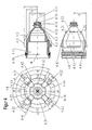
- the in the FIG. 1 shown plasma burner head 1 takes with an electrode holder 6, an electrode 7 in the present case via a thread (not shown).
- the electrode 7 is formed as a flat electrode.
- air or oxygen can be used as the plasma gas (PG).
- a nozzle 4 is received by a substantially cylindrical nozzle holder 5.
- a nozzle cap 2 which is attached via a thread (not shown) to the plasma burner head 1, fixed the nozzle 4 and forms with this a cooling liquid space.
- the coolant space is sealed between the nozzle 4 and the nozzle cap 2 by a seal realized with a circular ring 4.16, which is located in a groove 4.15 of the nozzle 4, and by a seal realized with a circular ring 4.18, which is located in a groove 4.17. sealed between the nozzle 4 and the nozzle holder 5.
- a cooling liquid eg. As water or antifreeze added water flows through the coolant space from a bore of the coolant flow WV to a bore of the coolant return WR, wherein the holes are arranged offset by 90 ° to each other (s. Fig. 1b ).
- the cooling liquid is passed approximately perpendicular to the longitudinal axis of the plasma burner head 1 of the nozzle holder 5 on the nozzle 4 aptly into the cooling liquid space.
- the cooling liquid from the direction parallel to the longitudinal axis in the bore of the cooling liquid flow WV of the plasma torch in the direction of the first section 4.1 (s. Fig. 2 ) is deflected almost perpendicular to the longitudinal axis of the plasma burner head 1.
- the cooling liquid flows through a groove 4.6 (s. Fig.
- the plasma burner head 1 is equipped with a nozzle protection cap holder 8 and a nozzle protection cap 9. Through this area flows a Sekundärgas'SG, which surrounds the plasma jet.
- the secondary gas SG flows through a secondary gas guide 9.1 and can be rotated by them.
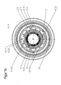
- Fig. 1a shows a sectional view along the line AA of the plasma torch FIG. 1 , This shows how the through thedeckenkeitszulaufnut 4.20 of the nozzle 4 and the nozzle cap 2 formed part 10.11 by sections 4.41 and 4.42 of outwardly projecting portions 4.31 and 4.32 of the nozzle 4 in combination with the inner surface 2.5 of the nozzle cap 2 prevent a shunt between the coolant flow and coolant return.
- an effective cooling of the nozzle 4 is achieved in the region of the nozzle tip and prevents thermal overload. It is ensured that as much coolant as possible reaches the part 10.20 of the coolant space.
- FIG. 1b includes a sectional view along the line BB of the plasma burner head of FIG. 1 , Which shows the plane of the deflection space 10.10 and the connection of the cooling liquid flow over the approximately 110 ° circumferential groove 4.6 in the nozzle 4 and the offset by 90 ° arranged holes for the coolant flow WV and coolant return WR.
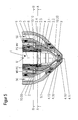
- Fig. 2 shows the nozzle 4 of the plasma burner head of FIG. 1 , It has a nozzle bore 4.10 for the exit of a plasma jet at a nozzle tip 4.11, a first section 4.1, the outer surface 4.4 is substantially cylindrical, and adjoining the nozzle tip 4.11 second section 4.2, the outer surface of the 4.5 to the nozzle tip 4.11 out in essentially conically tapered.
- Thedestattkeitszulaufnut 4.20 extends over a portion of the first section 4.1 and the second section 4.2 in the outer surface 4.5 of the nozzle 4 to the nozzle tip 4.11 and ends in front of the cylindrical outer surface 4.3.
- Thedestattkeits Weglaufnut 4.22 extends over the second section 4.2 of the nozzle 4.
- the center of thedeckenkeitszulaufnut 4.20 and the center of thedeckensschreiblaufnut 4.22 are offset by 180 ° to each other over the circumference of the nozzle 4.
- Between thedeckenkeitsvorlaufnut 4.20 and thedeckensschreiblaufnut 4.22 are the outwardly projecting portions 4.31 and 4.32 with the corresponding sections 4.41 and 4.42.
- FIG. 3 shows a nozzle according to another specific embodiment of the invention, which also in the plasma burner head after FIG. 1 can be used.
- Thedestattkeitszulaufnut 4.20 is connected to a groove 4.6, which extends here in the circumferential direction over the entire circumference.
- This has the advantage that the bore for the coolant flow WV and the coolant return WR in the plasma burner head can be arranged offset as desired.
- this is advantageous for the cooling of the transition between the nozzle holder 5 and the nozzle 4.
- the same can, of course, also be used in principle for a cooling liquid return groove 4.22.
- FIG. 4 shows a nozzle according to another specific embodiment of the invention, which also in the plasma burner head after FIG. 1 can be used .
- Thedestattkeitszulaufnuten 4.20 and 4.21 extend over a portion of the first section 4.1 and the second section 4.2 in the outer surface 4.5 of the nozzle 4 to the nozzle tip 4.11 and end in front of the cylindrical outer surface 4.3.
- the coolant return grooves 4.22 and 4.23 extend over the second section 4.2 of the nozzle 4.
- Thedeckenkeitszulaufnuten 4.20 and 4.21 are connected by a circumferential direction of the first section 4.1 of the nozzle 4 on a partial circumference between the grooves 4.20 and 4.21, ie over approximately 160 ° extending groove 4.6 of the nozzle 4 with each other.
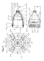
- FIG. 5 illustrates a plasma burner head according to another specific embodiment of the invention.
- the cooling liquid is directed to a nozzle in a coolant liquid space nearly perpendicularly to the longitudinal axis of the plasma burner head 1 from a nozzle holder 5 to the nozzle 4.
- the cooling liquid is deflected from the direction parallel to the longitudinal axis in the bore of the cooling liquid flow WV of the plasma burner in the direction of the first nozzle section 4.1 almost perpendicular to the longitudinal axis of the plasma burner head 1.
- the cooling liquid flows through the parts 10.11 and 10.12 formed by the cooling liquid supply grooves 4.20 and 4.21 of the nozzle 4 and the nozzle cap 2 (see FIG. Fig. 5a ) into the nozzle bore 4.10 surrounding area 10.20 of the cooling liquid space and flows around the nozzle 4 there. Thereafter, the cooling liquid flows through the parts 10.15 and 10.16 formed by the cooling liquid return grooves 4.22 and 4.23 of the nozzle 4 and the nozzle cap 2 back to the coolant return WR, wherein the transition takes place here almost perpendicular to the longitudinal axis of the plasma burner head, through the deflection 10.9.
- Fig. 5a is a sectional view taken along the line AA of the plasma burner head of FIG. 5 showing how the parts 10.11 and 10.12 formed by the cooling liquid inlet grooves 4.20 and 4.21 of the nozzle 4 and the nozzle cap 2 pass through the sections 4.41 and 4.42 of the protruding areas 4.31 and 4.32 of the nozzle 4 in combination with the inside surface of the nozzle cap 2 Prevent the coolant inlets and coolant returns. At the same time, a shunt between the parts 10.11 and 10.12 is prevented by the section 4.43 of the protruding section 4.33 and between the parts 10.15 and 10.16 by the section 4.44 of the protruding section 4.43.
- FIG. 5b is a sectional view taken along the line BB of the plasma burner head of FIG. 7 showing the plane of the deflection 10.9 and 10.10.
- Fig. 6 shows the nozzle 4 of the plasma burner head of FIG. 5 , It has a nozzle bore 4.10 for the exit of a plasma jet at a nozzle tip 4.11, a first section 4.1, the outer surface 4.4 is substantially cylindrical, and adjoining the nozzle tip 4.11 second section 4.2, the outer surface of the 4.5 to the nozzle tip 4.11 out in essentially conically tapered.
- Thedefactkeitszulaufnuten 4.20 and 4.21 and thedeckenkeits Weglaufnuten 4.22 and 4.23 extend over a portion of the first section 4.1 and the second section 4.2 in the outer surface 4.5 of the nozzle 4 to the nozzle tip 4.11 and end in front of the cylindrical outer surface 4.3.
- the center of thedeckenkeitszulaufnut 4.20 and the center of thedeckenkeitsschreiblaufnut 4.22 and the center of thedeckenkeitszulaufnut 4.21 and the center of thedeckenkeitsschreiblaufnut 4.23 are offset by 180 ° to each other over the circumference of the nozzle 4 and the same size.
- the (angular) widths of the fluid inlet grooves may be different. The same applies to the (angular) widths of the liquid return grooves.
- FIG. 7 shows individual representations of a in the plasma burner head 1 of FIG. 1
- the nozzle cap 2 has a substantially conically tapered inner surface 2.2, which has fourteen recesses 2.6 in a radial plane in this case.
- the recesses 2.6 are arranged equidistantly over the inner circumference and semicircular in the radial section.
Priority Applications (3)
| Application Number | Priority Date | Filing Date | Title |
|---|---|---|---|
| PL10732275T PL2449862T3 (pl) | 2009-07-03 | 2010-05-31 | Dysza do chłodzonego cieczą palnika plazmowego oraz głowica palnika plazmowego z taką dyszą |
| SI201031051T SI2449862T1 (sl) | 2009-07-03 | 2010-05-31 | Šoba za tekočinsko hlajeni plazemski gorilnik in glava plazemskega gorilnika, ki jo prav tako vsebuje |
| HRP20151177TT HRP20151177T1 (hr) | 2009-07-03 | 2015-11-04 | Mlaznica za tekućinski hlađeni plazmatski plamenik, kao i glava plazmatskog plamenika koja sadrži istu |
Applications Claiming Priority (3)
| Application Number | Priority Date | Filing Date | Title |
|---|---|---|---|
| DE102009031857.7A DE102009031857C5 (de) | 2009-07-03 | 2009-07-03 | Düse für einen flüssigkeitsgekühlten Plasmabrenner sowie Plasmabrennerkopf mit derselben |
| DE102009060849A DE102009060849A1 (de) | 2009-12-30 | 2009-12-30 | Düse für einen flüssigkeitsgekühlten Plasmabrenner sowie Plasmabrennerkopf mit derselben |
| PCT/DE2010/000608 WO2011000337A1 (de) | 2009-07-03 | 2010-05-31 | Düse für einen flüssigkeitsgekühlten plasmabrenner sowie plasmabrennerkopf mit derselben |
Publications (2)
| Publication Number | Publication Date |
|---|---|
| EP2449862A1 EP2449862A1 (de) | 2012-05-09 |
| EP2449862B1 true EP2449862B1 (de) | 2015-09-02 |
Family
ID=42712733
Family Applications (1)
| Application Number | Title | Priority Date | Filing Date |
|---|---|---|---|
| EP10732275.2A Active EP2449862B1 (de) | 2009-07-03 | 2010-05-31 | Düse für einen flüssigkeitsgekühlten plasmabrenner sowie plasmabrennerkopf mit derselben |
Country Status (16)
| Country | Link |
|---|---|
| US (1) | US8853589B2 (ko) |
| EP (1) | EP2449862B1 (ko) |
| JP (2) | JP2012531697A (ko) |
| KR (1) | KR101782171B1 (ko) |
| CN (1) | CN102474969B (ko) |
| BR (1) | BR112012000082B1 (ko) |
| CA (1) | CA2765449C (ko) |
| ES (1) | ES2554618T3 (ko) |
| HR (1) | HRP20151177T1 (ko) |
| HU (1) | HUE026032T2 (ko) |
| MX (1) | MX2011013814A (ko) |
| PL (1) | PL2449862T3 (ko) |
| RU (1) | RU2533187C2 (ko) |
| SI (1) | SI2449862T1 (ko) |
| WO (1) | WO2011000337A1 (ko) |
| ZA (1) | ZA201200022B (ko) |
Families Citing this family (14)
| Publication number | Priority date | Publication date | Assignee | Title |
|---|---|---|---|---|
| CA2765449C (en) * | 2009-07-03 | 2014-10-21 | Kjellberg Finsterwalde Plasma Und Maschinen Gmbh | Nozzle for a liquid-cooled plasma torch and plasma torch head having the same |
| EP2681975B1 (en) * | 2011-02-28 | 2016-04-20 | Victor Equipment Company | High current electrode for a plasma arc torch |
| EP2942144A1 (de) * | 2014-05-07 | 2015-11-11 | Kjellberg-Stiftung | Plasmaschneidbrenneranordnung sowie die Verwendung von Verschleißteilen bei einer Plasmaschneidbrenneranordnung |
| DE102015101532A1 (de) * | 2015-02-03 | 2016-08-04 | Kjellberg Stiftung | Düse für Plasmalichtbogenbrenner |
| US9867268B2 (en) * | 2015-06-08 | 2018-01-09 | Hypertherm, Inc. | Cooling plasma torch nozzles and related systems and methods |
| DE102016209394A1 (de) | 2015-07-13 | 2017-01-19 | Hypertherm, Inc. | Plasmaschneidedüsen mit integrierter Strömungsverteilung und damit verbundene Systeme und Verfahren |
| CN207013853U (zh) | 2016-04-11 | 2018-02-16 | 海别得公司 | 通用的冷却剂管 |
| KR20180000059U (ko) | 2016-06-27 | 2018-01-04 | 곽현만 | 플라즈마 토치용 노즐 |
| DE102016214146A1 (de) * | 2016-08-01 | 2018-02-01 | Kjellberg Stiftung | Plasmabrenner |
| US10917961B2 (en) * | 2017-09-13 | 2021-02-09 | Lincoln Global, Inc. | High temperature isolating insert for plasma cutting torch |
| DE102018100917A1 (de) * | 2017-09-22 | 2019-03-28 | Kjellberg-Stiftung | Düse für einen Plasmabrennerkopf, Laserschneidkopf und Plasma-Laser-Schneidkopf, Anordnungen, Plasmabrennerkopf und Plasmabrenner mit selbiger/selbigen, Laserschneidkopf mit selbiger/selbigen und Plasma-Laser-Schneidkopf mit selbiger/selbigen |
| KR102073815B1 (ko) * | 2017-12-15 | 2020-02-05 | 오텍캐리어 주식회사 | 플라즈마 제트 분사 구조를 가지는 소독장치 |
| DE102018125772A1 (de) * | 2018-07-27 | 2020-01-30 | Kjellberg-Stiftung | Verbindungsteil für einen Bearbeitungskopf zur thermischen Materialbearbeitung, insbesondere für einen Plasmabrennerkopf, Laserkopf, Plasma-Laser-Kopf sowie ein Verschleißteil und eine Verschleißteilhalterung und ein Verfahren zum Fügen dieser |
| US20210219412A1 (en) * | 2020-01-09 | 2021-07-15 | Hypertherm, Inc. | Nozzles for liquid cooled plasma arc cutting torches with clocking-independent passages |
Family Cites Families (30)
| Publication number | Priority date | Publication date | Assignee | Title |
|---|---|---|---|---|
| DD36014A1 (de) | 1964-05-19 | 1965-02-05 | Düse für Plasmabrenner | |
| DE1565638A1 (de) | 1967-06-12 | 1970-04-16 | Kjellberg Elektroden & Maschin | Plasmabrenner |
| DE1524887A1 (de) | 1967-12-09 | 1971-05-19 | Robotron Veb K | Verfahren zum Einschreiben von Informationen in magnetische Duennschichtspeicher |
| DD83890A1 (de) | 1970-05-27 | 1971-08-12 | Kühlmediumführung für Brenner | |
| DE2525939A1 (de) | 1975-06-11 | 1976-12-23 | Messer Griesheim Gmbh | Plasmalichtbogenbrenner |
| CH607540A5 (ko) | 1976-02-16 | 1978-12-29 | Niklaus Mueller | |
| JPS5528032U (ko) * | 1978-08-11 | 1980-02-23 | ||
| JPS5546266A (en) * | 1978-09-28 | 1980-03-31 | Daido Steel Co Ltd | Plasma torch |
| JPS57123700A (en) * | 1981-01-23 | 1982-08-02 | Hitachi Ltd | Plasma torch |
| JPS632230Y2 (ko) * | 1981-02-17 | 1988-01-20 | ||
| US5396043A (en) | 1988-06-07 | 1995-03-07 | Hypertherm, Inc. | Plasma arc cutting process and apparatus using an oxygen-rich gas shield |
| DE4022111A1 (de) | 1990-07-11 | 1992-01-23 | Krupp Gmbh | Plasmabrenner fuer uebertragenen lichtbogen |
| DE4030541C2 (de) | 1990-09-27 | 1997-10-02 | Dilthey Ulrich Prof Dr Ing | Brenner zur Beschichtung von Grundwerkstoffen mit pulverförmigen Zusatzwerkstoffen |
| US5393952A (en) | 1991-02-28 | 1995-02-28 | Kabushiki Kaisha Komatsu Seisakusho | Plasma torch for cutting use with nozzle protection cap having annular secondary GPS passage and insulator disposed in the secondary gas passage |
| JPH08288095A (ja) * | 1995-04-19 | 1996-11-01 | Komatsu Ltd | プラズマアークトーチ用電極 |
| JP3307820B2 (ja) * | 1996-02-07 | 2002-07-24 | 株式会社田中製作所 | プラズマ電極の消耗検出方法 |
| US5756959A (en) | 1996-10-28 | 1998-05-26 | Hypertherm, Inc. | Coolant tube for use in a liquid-cooled electrode disposed in a plasma arc torch |
| US5893985A (en) * | 1997-03-14 | 1999-04-13 | The Lincoln Electric Company | Plasma arc torch |
| US6268583B1 (en) | 1999-05-21 | 2001-07-31 | Komatsu Ltd. | Plasma torch of high cooling performance and components therefor |
| US7132619B2 (en) * | 2003-04-07 | 2006-11-07 | Thermal Dynamics Corporation | Plasma arc torch electrode |
| US20080116179A1 (en) | 2003-04-11 | 2008-05-22 | Hypertherm, Inc. | Method and apparatus for alignment of components of a plasma arc torch |
| JP2005118816A (ja) * | 2003-10-16 | 2005-05-12 | Koike Sanso Kogyo Co Ltd | プラズマトーチ用のノズル |
| CN2807699Y (zh) * | 2005-07-06 | 2006-08-16 | 张旭 | 大电流等离子焊枪 |
| SE529056C2 (sv) * | 2005-07-08 | 2007-04-17 | Plasma Surgical Invest Ltd | Plasmaalstrande anordning, plasmakirurgisk anordning och användning av en plasmakirurgisk anordning |
| DE102007005316B4 (de) * | 2006-08-16 | 2009-12-03 | Kjellberg Finsterwalde Plasma Und Maschinen Gmbh | Verbindung zwischen einem Plasmabrennerverschleißteil und einer Plasmabrennerverschleißteilhalterung, Plasmabrennerverschleißteil und Plasmabrennerverschleißteilhalterung |
| US8772667B2 (en) * | 2007-02-09 | 2014-07-08 | Hypertherm, Inc. | Plasma arch torch cutting component with optimized water cooling |
| US8389887B2 (en) * | 2008-03-12 | 2013-03-05 | Hypertherm, Inc. | Apparatus and method for a liquid cooled shield for improved piercing performance |
| DE102009006132C5 (de) | 2008-10-09 | 2015-06-03 | Kjellberg Finsterwalde Plasma Und Maschinen Gmbh | Düse für einen flüssigkeitsgekühlten Plasmabrenner, Düsenkappe für einen flüssigkeitsgekühlten Plasmabrenner sowie Plasmabrennerkopf mit derselben/denselben |
| CA2765449C (en) | 2009-07-03 | 2014-10-21 | Kjellberg Finsterwalde Plasma Und Maschinen Gmbh | Nozzle for a liquid-cooled plasma torch and plasma torch head having the same |
| DE102009031857C5 (de) | 2009-07-03 | 2017-05-11 | Kjellberg Finsterwalde Plasma Und Maschinen Gmbh | Düse für einen flüssigkeitsgekühlten Plasmabrenner sowie Plasmabrennerkopf mit derselben |
-
2010
- 2010-05-31 CA CA2765449A patent/CA2765449C/en active Active
- 2010-05-31 EP EP10732275.2A patent/EP2449862B1/de active Active
- 2010-05-31 US US13/382,067 patent/US8853589B2/en active Active
- 2010-05-31 ES ES10732275.2T patent/ES2554618T3/es active Active
- 2010-05-31 CN CN201080029498.4A patent/CN102474969B/zh active Active
- 2010-05-31 WO PCT/DE2010/000608 patent/WO2011000337A1/de active Application Filing
- 2010-05-31 MX MX2011013814A patent/MX2011013814A/es active IP Right Grant
- 2010-05-31 PL PL10732275T patent/PL2449862T3/pl unknown
- 2010-05-31 HU HUE10732275A patent/HUE026032T2/en unknown
- 2010-05-31 BR BR112012000082-9A patent/BR112012000082B1/pt not_active IP Right Cessation
- 2010-05-31 JP JP2012516507A patent/JP2012531697A/ja active Pending
- 2010-05-31 SI SI201031051T patent/SI2449862T1/sl unknown
- 2010-05-31 KR KR1020117031304A patent/KR101782171B1/ko active IP Right Grant
- 2010-05-31 RU RU2012103568/07A patent/RU2533187C2/ru active
-
2012
- 2012-01-03 ZA ZA2012/00022A patent/ZA201200022B/en unknown
-
2015
- 2015-04-01 JP JP2015074877A patent/JP6130870B2/ja active Active
- 2015-11-04 HR HRP20151177TT patent/HRP20151177T1/hr unknown
Also Published As
| Publication number | Publication date |
|---|---|
| PL2449862T3 (pl) | 2016-01-29 |
| SI2449862T1 (sl) | 2015-12-31 |
| JP6130870B2 (ja) | 2017-05-17 |
| BR112012000082A2 (pt) | 2016-03-15 |
| US8853589B2 (en) | 2014-10-07 |
| EP2449862A1 (de) | 2012-05-09 |
| KR101782171B1 (ko) | 2017-10-23 |
| MX2011013814A (es) | 2012-02-13 |
| ES2554618T3 (es) | 2015-12-22 |
| BR112012000082B1 (pt) | 2019-09-24 |
| RU2533187C2 (ru) | 2014-11-20 |
| KR20120032491A (ko) | 2012-04-05 |
| JP2015167133A (ja) | 2015-09-24 |
| RU2012103568A (ru) | 2013-08-10 |
| WO2011000337A1 (de) | 2011-01-06 |
| CA2765449A1 (en) | 2011-01-06 |
| HRP20151177T1 (hr) | 2015-12-04 |
| ZA201200022B (en) | 2013-04-24 |
| CN102474969A (zh) | 2012-05-23 |
| US20120138579A1 (en) | 2012-06-07 |
| HUE026032T2 (en) | 2016-05-30 |
| CA2765449C (en) | 2014-10-21 |
| JP2012531697A (ja) | 2012-12-10 |
| CN102474969B (zh) | 2014-11-26 |
Similar Documents
| Publication | Publication Date | Title |
|---|---|---|
| EP2175702B1 (de) | Düse und Düsenkappe für einen flüssigkeitsgekühlten Plasmabrenner sowie Plasmabrennerkopf mit derselben/denselben | |
| EP2449862B1 (de) | Düse für einen flüssigkeitsgekühlten plasmabrenner sowie plasmabrennerkopf mit derselben | |
| EP2140739B1 (de) | Düse für einen flüssigkeitsgekühlten plasmabrenner, anordnung aus derselben und einer düsenkappe sowie flüssigkeitsgekühlter plasmabrenner mit einer derartigen anordnung | |
| DE102004049445C5 (de) | Plasmabrenner | |
| EP2465334B1 (de) | Düsenschutzkappe und düsenschutzkappenhalter sowie lichtbogenplasmabrenner mit derselben und/oder demselben | |
| EP2417840B1 (de) | Kühlrohre, elektrodenaufnahmen und elektrode für einen lichtbogenplasmabrenner sowie anordnungen aus denselben und lichtbogenplasmabrenner mit denselben | |
| EP2210455B1 (de) | Elektrode für einen plasmabrenner | |
| DE102011088433A1 (de) | Verfahren und Plasmalichtbogenbrennersystem zum Markieren und Schneiden von Werkstücken mit dem selben Satz an Hilfsstoffen | |
| EP3639631A2 (de) | Elektroden für gas- und flüssigkeitsgekühlte plasmabrenner, anordnung aus einer elektrode und einem kühlrohr, gasführung, plasmabrenner, verfahren zur gasführung in einem plasmabrenner und verfahren zum betreiben eines plasmabrenners | |
| DE102009031857C5 (de) | Düse für einen flüssigkeitsgekühlten Plasmabrenner sowie Plasmabrennerkopf mit derselben | |
| EP2531320B1 (de) | Düse für einen flüssigkeitsgekühlten plasma-schneidbrenner mit nuten | |
| EP2667689B1 (de) | Elektrode für Plasmaschneidbrenner sowie deren Verwendung | |
| EP2457681A1 (de) | Brenner für das Wolfram-Inertgas-Schweißen sowie Elektrode zur Verwendung bei einem solchen Brenner | |
| DE102009060849A1 (de) | Düse für einen flüssigkeitsgekühlten Plasmabrenner sowie Plasmabrennerkopf mit derselben | |
| DE202009012491U1 (de) | Düse für einen flüssigkeitsgekühlten Plasmabrenner sowie Plasmabrennerkopf mit derselben |
Legal Events
| Date | Code | Title | Description |
|---|---|---|---|
| TPAC | Observations filed by third parties |
Free format text: ORIGINAL CODE: EPIDOSNTIPA |
|
| PUAI | Public reference made under article 153(3) epc to a published international application that has entered the european phase |
Free format text: ORIGINAL CODE: 0009012 |
|
| 17P | Request for examination filed |
Effective date: 20110113 |
|
| AK | Designated contracting states |
Kind code of ref document: A1 Designated state(s): AL AT BE BG CH CY CZ DE DK EE ES FI FR GB GR HR HU IE IS IT LI LT LU LV MC MK MT NL NO PL PT RO SE SI SK SM TR |
|
| DAX | Request for extension of the european patent (deleted) | ||
| RAP1 | Party data changed (applicant data changed or rights of an application transferred) |
Owner name: KJELLBERG FINSTERWALDE PLASMA UND MASCHINEN GMBH |
|
| 17Q | First examination report despatched |
Effective date: 20141104 |
|
| GRAP | Despatch of communication of intention to grant a patent |
Free format text: ORIGINAL CODE: EPIDOSNIGR1 |
|
| INTG | Intention to grant announced |
Effective date: 20150515 |
|
| GRAS | Grant fee paid |
Free format text: ORIGINAL CODE: EPIDOSNIGR3 |
|
| GRAA | (expected) grant |
Free format text: ORIGINAL CODE: 0009210 |
|
| AK | Designated contracting states |
Kind code of ref document: B1 Designated state(s): AL AT BE BG CH CY CZ DE DK EE ES FI FR GB GR HR HU IE IS IT LI LT LU LV MC MK MT NL NO PL PT RO SE SI SK SM TR |
|
| REG | Reference to a national code |
Ref country code: GB Ref legal event code: FG4D Free format text: NOT ENGLISH |
|
| REG | Reference to a national code |
Ref country code: AT Ref legal event code: REF Ref document number: 747309 Country of ref document: AT Kind code of ref document: T Effective date: 20150915 Ref country code: CH Ref legal event code: EP |
|
| REG | Reference to a national code |
Ref country code: IE Ref legal event code: FG4D Free format text: LANGUAGE OF EP DOCUMENT: GERMAN |
|
| REG | Reference to a national code |
Ref country code: DE Ref legal event code: R096 Ref document number: 502010010204 Country of ref document: DE Ref country code: CH Ref legal event code: NV Representative=s name: KAMINSKI HARMANN PATENTANWAELTE AG, LI |
|
| REG | Reference to a national code |
Ref country code: HR Ref legal event code: TUEP Ref document number: P20151177 Country of ref document: HR |
|
| REG | Reference to a national code |
Ref country code: HR Ref legal event code: T1PR Ref document number: P20151177 Country of ref document: HR |
|
| REG | Reference to a national code |
Ref country code: SE Ref legal event code: TRGR Ref country code: ES Ref legal event code: FG2A Ref document number: 2554618 Country of ref document: ES Kind code of ref document: T3 Effective date: 20151222 |
|
| REG | Reference to a national code |
Ref country code: NL Ref legal event code: FP |
|
| PG25 | Lapsed in a contracting state [announced via postgrant information from national office to epo] |
Ref country code: GR Free format text: LAPSE BECAUSE OF FAILURE TO SUBMIT A TRANSLATION OF THE DESCRIPTION OR TO PAY THE FEE WITHIN THE PRESCRIBED TIME-LIMIT Effective date: 20151203 Ref country code: LT Free format text: LAPSE BECAUSE OF FAILURE TO SUBMIT A TRANSLATION OF THE DESCRIPTION OR TO PAY THE FEE WITHIN THE PRESCRIBED TIME-LIMIT Effective date: 20150902 Ref country code: LV Free format text: LAPSE BECAUSE OF FAILURE TO SUBMIT A TRANSLATION OF THE DESCRIPTION OR TO PAY THE FEE WITHIN THE PRESCRIBED TIME-LIMIT Effective date: 20150902 Ref country code: NO Free format text: LAPSE BECAUSE OF FAILURE TO SUBMIT A TRANSLATION OF THE DESCRIPTION OR TO PAY THE FEE WITHIN THE PRESCRIBED TIME-LIMIT Effective date: 20151202 |
|
| REG | Reference to a national code |
Ref country code: LT Ref legal event code: MG4D |
|
| RAP2 | Party data changed (patent owner data changed or rights of a patent transferred) |
Owner name: KJELLBERG FINSTERWALDE PLASMA UND MASCHINEN GMBH |
|
| PG25 | Lapsed in a contracting state [announced via postgrant information from national office to epo] |
Ref country code: IS Free format text: LAPSE BECAUSE OF FAILURE TO SUBMIT A TRANSLATION OF THE DESCRIPTION OR TO PAY THE FEE WITHIN THE PRESCRIBED TIME-LIMIT Effective date: 20160102 Ref country code: EE Free format text: LAPSE BECAUSE OF FAILURE TO SUBMIT A TRANSLATION OF THE DESCRIPTION OR TO PAY THE FEE WITHIN THE PRESCRIBED TIME-LIMIT Effective date: 20150902 |
|
| REG | Reference to a national code |
Ref country code: FR Ref legal event code: PLFP Year of fee payment: 7 |
|
| REG | Reference to a national code |
Ref country code: HU Ref legal event code: AG4A Ref document number: E026032 Country of ref document: HU |
|
| PG25 | Lapsed in a contracting state [announced via postgrant information from national office to epo] |
Ref country code: RO Free format text: LAPSE BECAUSE OF FAILURE TO SUBMIT A TRANSLATION OF THE DESCRIPTION OR TO PAY THE FEE WITHIN THE PRESCRIBED TIME-LIMIT Effective date: 20150902 Ref country code: PT Free format text: LAPSE BECAUSE OF FAILURE TO SUBMIT A TRANSLATION OF THE DESCRIPTION OR TO PAY THE FEE WITHIN THE PRESCRIBED TIME-LIMIT Effective date: 20160104 |
|
| REG | Reference to a national code |
Ref country code: SK Ref legal event code: T3 Ref document number: E 20125 Country of ref document: SK |
|
| REG | Reference to a national code |
Ref country code: DE Ref legal event code: R097 Ref document number: 502010010204 Country of ref document: DE |
|
| PLBE | No opposition filed within time limit |
Free format text: ORIGINAL CODE: 0009261 |
|
| STAA | Information on the status of an ep patent application or granted ep patent |
Free format text: STATUS: NO OPPOSITION FILED WITHIN TIME LIMIT |
|
| 26N | No opposition filed |
Effective date: 20160603 |
|
| PG25 | Lapsed in a contracting state [announced via postgrant information from national office to epo] |
Ref country code: DK Free format text: LAPSE BECAUSE OF FAILURE TO SUBMIT A TRANSLATION OF THE DESCRIPTION OR TO PAY THE FEE WITHIN THE PRESCRIBED TIME-LIMIT Effective date: 20150902 |
|
| PG25 | Lapsed in a contracting state [announced via postgrant information from national office to epo] |
Ref country code: LU Free format text: LAPSE BECAUSE OF FAILURE TO SUBMIT A TRANSLATION OF THE DESCRIPTION OR TO PAY THE FEE WITHIN THE PRESCRIBED TIME-LIMIT Effective date: 20160531 |
|
| REG | Reference to a national code |
Ref country code: IE Ref legal event code: MM4A |
|
| REG | Reference to a national code |
Ref country code: FR Ref legal event code: PLFP Year of fee payment: 8 |
|
| PG25 | Lapsed in a contracting state [announced via postgrant information from national office to epo] |
Ref country code: IE Free format text: LAPSE BECAUSE OF NON-PAYMENT OF DUE FEES Effective date: 20160531 |
|
| REG | Reference to a national code |
Ref country code: HU Ref legal event code: HC9C |
|
| REG | Reference to a national code |
Ref country code: FR Ref legal event code: PLFP Year of fee payment: 9 |
|
| PG25 | Lapsed in a contracting state [announced via postgrant information from national office to epo] |
Ref country code: CY Free format text: LAPSE BECAUSE OF FAILURE TO SUBMIT A TRANSLATION OF THE DESCRIPTION OR TO PAY THE FEE WITHIN THE PRESCRIBED TIME-LIMIT Effective date: 20150902 Ref country code: SM Free format text: LAPSE BECAUSE OF FAILURE TO SUBMIT A TRANSLATION OF THE DESCRIPTION OR TO PAY THE FEE WITHIN THE PRESCRIBED TIME-LIMIT Effective date: 20150902 |
|
| PG25 | Lapsed in a contracting state [announced via postgrant information from national office to epo] |
Ref country code: MT Free format text: LAPSE BECAUSE OF FAILURE TO SUBMIT A TRANSLATION OF THE DESCRIPTION OR TO PAY THE FEE WITHIN THE PRESCRIBED TIME-LIMIT Effective date: 20150902 Ref country code: MC Free format text: LAPSE BECAUSE OF FAILURE TO SUBMIT A TRANSLATION OF THE DESCRIPTION OR TO PAY THE FEE WITHIN THE PRESCRIBED TIME-LIMIT Effective date: 20150902 Ref country code: MK Free format text: LAPSE BECAUSE OF FAILURE TO SUBMIT A TRANSLATION OF THE DESCRIPTION OR TO PAY THE FEE WITHIN THE PRESCRIBED TIME-LIMIT Effective date: 20150902 |
|
| PG25 | Lapsed in a contracting state [announced via postgrant information from national office to epo] |
Ref country code: BG Free format text: LAPSE BECAUSE OF FAILURE TO SUBMIT A TRANSLATION OF THE DESCRIPTION OR TO PAY THE FEE WITHIN THE PRESCRIBED TIME-LIMIT Effective date: 20150902 |
|
| PG25 | Lapsed in a contracting state [announced via postgrant information from national office to epo] |
Ref country code: AL Free format text: LAPSE BECAUSE OF FAILURE TO SUBMIT A TRANSLATION OF THE DESCRIPTION OR TO PAY THE FEE WITHIN THE PRESCRIBED TIME-LIMIT Effective date: 20150902 |
|
| REG | Reference to a national code |
Ref country code: HR Ref legal event code: ODRP Ref document number: P20151177 Country of ref document: HR Payment date: 20190523 Year of fee payment: 10 |
|
| REG | Reference to a national code |
Ref country code: HR Ref legal event code: ODRP Ref document number: P20151177 Country of ref document: HR Payment date: 20200520 Year of fee payment: 11 |
|
| REG | Reference to a national code |
Ref country code: HR Ref legal event code: ODRP Ref document number: P20151177 Country of ref document: HR Payment date: 20210521 Year of fee payment: 12 |
|
| REG | Reference to a national code |
Ref country code: HR Ref legal event code: ODRP Ref document number: P20151177 Country of ref document: HR Payment date: 20220524 Year of fee payment: 13 |
|
| PGFP | Annual fee paid to national office [announced via postgrant information from national office to epo] |
Ref country code: TR Payment date: 20220525 Year of fee payment: 13 |
|
| REG | Reference to a national code |
Ref country code: HR Ref legal event code: ODRP Ref document number: P20151177 Country of ref document: HR Payment date: 20230519 Year of fee payment: 14 |
|
| PGFP | Annual fee paid to national office [announced via postgrant information from national office to epo] |
Ref country code: NL Payment date: 20230519 Year of fee payment: 14 Ref country code: IT Payment date: 20230531 Year of fee payment: 14 Ref country code: FR Payment date: 20230517 Year of fee payment: 14 Ref country code: ES Payment date: 20230621 Year of fee payment: 14 Ref country code: DE Payment date: 20230531 Year of fee payment: 14 Ref country code: CZ Payment date: 20230519 Year of fee payment: 14 Ref country code: CH Payment date: 20230605 Year of fee payment: 14 |
|
| PGFP | Annual fee paid to national office [announced via postgrant information from national office to epo] |
Ref country code: SK Payment date: 20230522 Year of fee payment: 14 Ref country code: SI Payment date: 20230519 Year of fee payment: 14 Ref country code: SE Payment date: 20230522 Year of fee payment: 14 Ref country code: PL Payment date: 20230518 Year of fee payment: 14 Ref country code: HU Payment date: 20230531 Year of fee payment: 14 Ref country code: HR Payment date: 20230519 Year of fee payment: 14 Ref country code: FI Payment date: 20230523 Year of fee payment: 14 Ref country code: AT Payment date: 20230516 Year of fee payment: 14 |
|
| PGFP | Annual fee paid to national office [announced via postgrant information from national office to epo] |
Ref country code: BE Payment date: 20230517 Year of fee payment: 14 |
|
| PGFP | Annual fee paid to national office [announced via postgrant information from national office to epo] |
Ref country code: GB Payment date: 20230522 Year of fee payment: 14 |