EP2448640B1 - Sprühkopf - Google Patents
Sprühkopf Download PDFInfo
- Publication number
- EP2448640B1 EP2448640B1 EP10793661.9A EP10793661A EP2448640B1 EP 2448640 B1 EP2448640 B1 EP 2448640B1 EP 10793661 A EP10793661 A EP 10793661A EP 2448640 B1 EP2448640 B1 EP 2448640B1
- Authority
- EP
- European Patent Office
- Prior art keywords
- spray head
- fixing body
- triggering element
- protection means
- medium
- Prior art date
- Legal status (The legal status is an assumption and is not a legal conclusion. Google has not performed a legal analysis and makes no representation as to the accuracy of the status listed.)
- Active
Links
Images


Classifications
-
- A—HUMAN NECESSITIES
- A62—LIFE-SAVING; FIRE-FIGHTING
- A62C—FIRE-FIGHTING
- A62C31/00—Delivery of fire-extinguishing material
- A62C31/02—Nozzles specially adapted for fire-extinguishing
-
- A—HUMAN NECESSITIES
- A62—LIFE-SAVING; FIRE-FIGHTING
- A62C—FIRE-FIGHTING
- A62C37/00—Control of fire-fighting equipment
- A62C37/08—Control of fire-fighting equipment comprising an outlet device containing a sensor, or itself being the sensor, i.e. self-contained sprinklers
- A62C37/09—Control of fire-fighting equipment comprising an outlet device containing a sensor, or itself being the sensor, i.e. self-contained sprinklers telescopic or adjustable
-
- A—HUMAN NECESSITIES
- A62—LIFE-SAVING; FIRE-FIGHTING
- A62C—FIRE-FIGHTING
- A62C37/00—Control of fire-fighting equipment
- A62C37/08—Control of fire-fighting equipment comprising an outlet device containing a sensor, or itself being the sensor, i.e. self-contained sprinklers
Definitions
- the object of the invention is a spray head comprising a spray head body, which comprises at least one nozzle, a heat-activated triggering element, in connection with the spray head of which a protection means is arranged, which protection means is in front of the nozzle in the protective position and mechanically protects the triggering element when the spray head is in a non-active state, and which protection means can be moved to a second position, in which at least one nozzle and the triggering element are not protected by the protection means.
- a spray head body which comprises at least one nozzle, a heat-activated triggering element, in connection with the spray head of which a protection means is arranged, which protection means is in front of the nozzle in the protective position and mechanically protects the triggering element when the spray head is in a non-active state, and which protection means can be moved to a second position, in which at least one nozzle and the triggering element are not protected by the protection means.
- One such spray head intended particularly for fire extinguishing is known e.g. from
- a solution is also known from publication WO 2007/082988 A1 , a sprinkler, in which the sprinkler body is formed to be movable and the sprinkler body exerts a force influence on a protection means that releases the protection means.
- the release of the protection means is achieved by arranging a relatively large part of the sprinkler, in terms of its mass, to be movable. This forms a sprinkler that is relatively complex in structure and makes the manufacturing costs of the component in question rather high.
- the solution according to the publication becomes rather big in its height, which is a significant drawback in applications in which the space available for the spray head is minimized. These types of applications are, among others, means of transportation, such as train carriages, or public spaces.
- the aim of this invention is to achieve a new type of spray head, the space requirement of which is minimal and by means of which the protection means can be dependably and effectively removed from in front of the spray nozzle and the triggering element.
- Another aim is to achieve, among other things, a simpler combination for a spray head that is excellent in terms of its operational reliability, more particularly for a spray head and for apparatuses for releasing the protection means of the spray head.
- the invention is based on a concept wherein the fixing body of the triggering means of the spray head is arranged to be moved between two positions, in which case the fixing body of the triggering means of the spray head functions as a releasing means of the protection means.
- the spray head according to the invention is characterized in that the triggering element is fitted onto the fixing body of the triggering element, which fixing body can be moved with respect to the spray head body between two positions, a first position in which the spray head is in the non-active state and the fixing body of the triggering element is in the retracted position, and a second position in which the fixing body of the triggering element is pushed out, and which fixing body of the triggering element is arranged to move with respect to the spray head body from the effect of the pressure of the medium from a first position to a second position and at the same time to exert a force on the protection means, for moving the protection means from the protective position to a second position, in which case the spray head is placed into a state of readiness in the second position of the fixing body of the triggering element.
- the solution according to the invention has a number of important advantages.
- the fixing body of the triggering means of the spray head By arranging the fixing body of the triggering means of the spray head to be movable and by using it to release the protective dome, an extremely well-functioning solution is obtained for bringing a spray head intended for difficult conditions into a state of readiness.
- the extinguishing medium for moving the spray head By using the extinguishing medium for moving the spray head, an advantageous combination for a means for removing the protection means from in front of the spray head is achieved.
- the valve spindle, or a part of it, of the spray head as a fixing body of the triggering means, sufficiently large surfaces can be obtained for converting the pressure of the medium into a moving force exerted on the protection means.
- By arranging the triggering element transversely on the fixing body By arranging the triggering element transversely on the fixing body, a space-saving construction is achieved.
- the spray head arrangement according to the invention can thus easily be connected to the applicable fixing parts.
- the solution is extremely well suited for disposing in circumstances in which protection of the spray head from, among other things, environmental conditions is necessary. These types of circumstances are e.g. public premises in which the available space is limited, such as means of transportation, e.g. trains.
- the solution is extremely well suited in particular to fire extinguishing applications, and more particularly to applications in which a medium mist of high liquid content is used as an extinguishing medium.
- Fig. 1 presents a spray head 1 according to the invention arranged on a fixing surface 10, such as on a ceiling, wall or corresponding surface.
- a pipeline 7, or corresponding medium conduit is arranged to the spray head, with which the medium to be sprayed is brought to the spray head.
- the pipeline is fixed to the fixing surface 10 with fastening devices 11.
- the wall or the ceiling structure comprises a cover board 9, such as a suspended ceiling, which is at a distance from the fixing surface, in which case a space 14 remains between the fixing surface 10 and the cover board 9 for the pipeline 7.
- An aperture 15 is formed in the cover board 9.
- a mounting box 8 is arranged in the aperture 15, the wall and base of which mounting box extend inwards from the aperture 15, i.e. in the figure towards the pipeline 7.
- a protection means 6 is arranged in front of at least one nozzle 3 of the spray head and in front of the triggering element 5.
- the protection means 6 in the embodiment of Fig. 1 is a plate, which is arranged to cover the aperture 15 and the spray head 1.
- a fastening means 17, which is arranged to suit a counterpart 16, is arranged on the protection means.
- the counterpart 16 is arranged in the mounting box 8 in the embodiment of the figures, but it can also be on the cover board 9, such as on the wall of the aperture 15.
- the protection means is arranged in the spray head. In this case the shape of the protection means can be e.g. domed.
- Fig. 1 presents a spray head 1 as a partial cross-section in a first position.
- the spray head is arranged on a fixing part that is arranged on the pipeline 7.
- the body part of the spray head i.e. the spray head body 2, is arranged on the fixing part.
- a triggering means 5 such as a heat-sensitive triggering means, e.g. an ampoule that breaks at a certain temperature, is arranged in the spray head.
- the triggering means 5 is arranged on the fixing body 4 of the triggering element.
- the triggering means 5 in the embodiment of the figure is fitted to extend in a space-saving manner in the lateral direction with respect to the fixing body 4 of the triggering element.
- the triggering element extends in the side direction in Fig. 1 , i.e. essentially in the direction of the cover board.
- the triggering means 5 is in this case according to Fig. 1 between the spray head body 2 and the protection means 6.
- the fixing body 4 of the triggering means is fitted to move with respect to the spray head body 2 at least between a first position, i.e. a non-active position, ( Fig. 1 ), and one second position, i.e. a position of readiness ( Fig. 2 ).
- At least one nozzle 3 is arranged in the body part 2 of the spray head.
- the spray head of the figure comprises a number of nozzles 3.
- a duct 13 is arranged in the spray head body 2, in which duct the fixing body 4 of the triggering element can move between a first position and a second position.
- the pressure acts on the surfaces of the fixing body of the triggering means, which surfaces are formed to be such that the fixing body of the triggering means moves from a first position in the duct 13 of the body part to a second position, i.e. up to the countersurface 18 of the duct space of the spray head body.
- the fixing body 4 of the triggering means comprises a shoulder 12, which corresponds to the countersurface 18 of the duct space of the spray head body.
- the shoulder 12 thus functions as a limiter part.
- the end 41 of the fixing body 4 on the protection means 6 side and/or the triggering element 5 acts on the protection means 6.
- the protection means 6 detaches from the locked position ( Fig. 1 ) and moves away from the front of the triggering means 5 and the nozzles of the spray head body ( Fig. 2 ).
- the spray head comprises a spray head body 2, which comprises at least one nozzle 3, a heat-activated triggering element 5 and a protection means 6, which protection means is in front of the nozzle 3 and mechanically protects the triggering element 5 when the spray head is in a non-active state, and which protection means 6 can be moved to a second position, in which the nozzles 3 and the triggering element 5 are not protected by the protection means 6.
- the fixing body 4 of the triggering element can be moved with respect to the spray head body 2 between two positions, a first position in which the spray head is in the non-active state, and a second position in which the fixing body 4 of the triggering element is pushed out, and which fixing body 4 of the triggering element is arranged to move with respect to the spray head body from the effect of the pressure of the medium from a first position to a second position and at the same time to exert force on the protection means 6 for moving it from the protective position to a second position, in which case the spray head is placed into a state of readiness in the second position of the fixing body 4 of the triggering element.
- the spray head body 2 comprises a duct part 13, i.e. a cylinder space, in which case at least a part of the fixing body 4 of the triggering element is formed into a piston part, which is arranged to move in the cylinder space from the effect of the pressure of the medium from a first position to a second position.
- the medium used for moving is typically an extinguishing medium. It is also possible to use some other applicable medium.
- the protection means 6 is fixed in the solution according to Fig. 1 in the protective position ( Fig. 1 ) into a ring-shaped counter-element 16 of the wall of the mounting box 8 arranged in the aperture 15 of the cover board 9.
- the ring-shaped counter-element 16 is arranged on the wall of the mounting box 8.
- a fixing part 17 is on the protection part 6.
- the fixing part 17 of the protection part and the ring-shaped counterpart 16 form a locking, which keeps the protection part in its position in the protective position.
- the protection means 6 stays in its position well in the protective position, in which case the important parts of the spray head are well protected from the effects of the environment of the spray head.
- the triggering means 5 typically an ampoule
- the nozzles 3 The spray head can be disposed in very different environments, in which it is subjected to impurities and to dirt or to vandalism, which may impair the operation of the spray head to, among other things, cause malfunctions of the spray head without the protection means 6.
- the protection means 6 prevents unwanted triggering of the triggering means 5, e.g. as a result of a short hot gas current directed onto the spray head.
- These types of situations can occur in, among other places, highway tunnels, in which e.g. the exhaust gas of a truck can momentarily be aimed directly towards the spray head, or as a result of vandalism, in which e.g. the flame of a lighter is deliberately aimed at the spray head.
- the spray head can be placed into a state of readiness by conducting the medium into the pipe 7 with pressure.
- the pressure of the medium is exerted against the surfaces of the fixing body of the triggering means of the spray head, in which case a force is produced that presses the fixing body of the triggering element from a first position in the spray head body towards a second position, i.e. downwards in Fig. 1 .
- the fixing body 4 of the triggering element acts on the protection means 6, in which case when the force exerted by the fixing body 4 of the triggering element on the protection means 6 exceeds the force that keeps the protection means in its position, the protection means detaches from its position to the non-protective position according to Fig. 2 .
- the fixing body in the figure acts at the point of its outermost part, i.e. the support part 41, on the protection means 6 in the direction of movement of the fixing body.
- the spray head can be activated in the normal way by the aid of the triggering means 5, e.g. when it is broken from the effect of heat, in which case the nozzles 3 can spray extinguishing medium.
- the first end of the fixing body of the triggering element according to the invention extends to some extent away from the spray head body, in which case it is, on the one hand, closer to a possible burning object and also a distance from the fixing point, e.g. from the surface of the ceiling or wall.
- the extinguishing medium pipe 7 is a so-called dry pipe, in which case there is no extinguishing medium in it.
- the extinguishing medium acts in the manner described above moving the fixing body of the triggering element from a first position to a second position and into a state of readiness, in which case also the protection means 6 detaches from its locking.
- the state of readiness after the ampoule 5 of the spray head has broken, e.g. from the effect of heat extinguishing medium starts to spray from the nozzles 3 of the spray head.
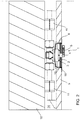
- Fig. 3 presents a spray head according to the invention when activated, in which case the triggering element has broken and at the same time the support part 41 of the triggering element has detached from the moving body 4 of the triggering element. In this case there is no part in front of the nozzles that possibly impedes the spraying.
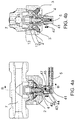
- Figs. 4a and 4c further present a cross-section of one spray head according to the invention.
- the invention thus relates to a spray head, which comprises a spray head body 2, which comprises at least one nozzle 3, a heat-activated triggering element 5, in connection with the spray head of which triggering element a protection means 6 is arranged, which protection means is in front of the nozzle 3 in the protective position and mechanically protects the triggering element 5 when the spray head is in a non-active state, and which protection means 6 can be moved to a second position, in which at least one nozzle 3 and the triggering element 5 are not protected by the protection means 6.
- the triggering element 5 is fitted onto the fixing body 4 of the triggering element, which fixing body can be moved with respect to the spray head body 2 between two positions, a first position in which the spray head is in the non-active state and the fixing body 4 of the triggering element is in the retracted position, and a second position in which the fixing body of the triggering element is pushed out, and which fixing body 4 of the triggering element is arranged to move with respect to the spray head body 2 from the effect of the pressure of the medium from a first position to a second position and at the same time to exert force on the protection means 6, for moving the protection means from the protective position to a second position, in which case the spray head is placed into a state of readiness in the second position of the fixing body of the triggering element. In the state of readiness, the spray head can be activated by activation of the triggering element.
- the spray head body 2 comprises a cylinder space 13, and at least a part of the fixing body 4 of the triggering element is formed into a piston part, which is arranged to move in the cylinder space 13 from the effect of the pressure of the medium from a first position to a second position.
- the fixing body 4 of the triggering element comprises a limiting means 12 of movement, such as a shoulder, and the spray head body 2 comprises a countersurface 18 to the limiting means.
- the triggering element 5 is preferably fitted to extend in the lateral direction with respect to the direction of movement of the fixing body 4 of the triggering element.
- the fixing body 4 of the triggering element comprises a support part 41, which is fitted to the end of the fixing body 4 of the triggering element on the protection means 6 side, when the protection means 6 protects the triggering element and at least one nozzle 3 of the spray head.
- the protection means 6 in the protective position is fitted into the aperture 15 of the cover board 9, into the mounting box 8, or into a corresponding installation aperture of the spray head.
- the support part 41 of the fixing body 4 of the triggering element is fitted to detach when the triggering element 5, such as an ampoule that breaks from the effect of heat, triggers and the spray head activates to spray.
- the spray head comprises a locking means 43, which comprises a first claw part 44 and a second claw part 45.
- the locking means 43 is fitted in a manner allowing rotation onto a support axle 46.
- the locking means 43 is able to rotate in relation to the support axle 46 so that the first claw part 44 in Fig. 4a moves some distance to the right and the second claw part 45, which locks the support part 41 to the fixing body of the triggering element, into its groove 47, moves upwards and releases the support part 41 from its locking in the groove 47 of the fixing body 4.
- a second way to fit the support part of the fixing body of the triggering element to detach can be achieved e.g. in the manner presented in publication WO 98/56463 , wherein the holder of the triggering element is fitted to detach.
- the fixing body 4 of the triggering element comprises a spraying nozzle 42 for spraying the medium in the activated state of the spray head.
- the spray head is typically fitted into a fire extinguishing system of a public space or of a means of transportation.
- the spray head according to the invention is very well suited to spraying an extinguishing medium of high liquid content.
Landscapes
- Health & Medical Sciences (AREA)
- Public Health (AREA)
- Business, Economics & Management (AREA)
- Emergency Management (AREA)
- Fire-Extinguishing By Fire Departments, And Fire-Extinguishing Equipment And Control Thereof (AREA)
- Nozzles (AREA)
Claims (10)
- Sprühkopf, der einen Sprühkopfkörper (2) umfasst, der mindestens eine Düse (3) sowie ein durch Wärme aktiviertes Auslöseelement (5) umfasst, wodurch bei Aktivierung in Verbindung mit dem Sprühkopf Medium aus der mindestens einen Düse strömen kann, wobei über dem Auslöseelement eine Schutzvorrichtung (6) angeordnet ist, die sich in der Schutzposition vor der Düse (3) befindet und das Auslöseelement (5) in einem nicht aktiven Zustand des Sprühkopfes mechanisch schützt, und die Schutzvorrichtung (6) in eine andere Position gebracht werden kann, in der die mindestens eine Düse (3) und das Auslöseelement (5) nicht durch die Schutzvorrichtung (6) geschützt sind, wobei das Auslöseelement (5) an einem Befestigungskörper (4) angebracht ist, der in Bezug auf den Sprühkopfkörper (2) zwischen zwei Positionen bewegt werden kann, einer ersten Position, in der sich der Sprühkopf im nicht aktiven Zustand befindet und der Befestigungskörper (4) in einer eingezogenen Position ist, und einer zweiten Position, in der der Befestigungskörper herausgeschoben ist, und wobei der Befestigungskörper (4) so angeordnet ist, dass er sich in Bezug auf den Sprühkopfkörper (2) unter der Wirkung des Drucks des Mediums von der ersten Position in die zweite Position bewegt und gleichzeitig eine Kraft auf die Schutzvorrichtung (6) ausübt, um die Schutzvorrichtung von der Schutzposition in die genannte andere Position zu bewegen, in der der Sprühkopf in einen betriebsbereiten Zustand in der zweiten Position des Befestigungskörpers versetzt wird, wobei im betriebsbereiten Zustand der Sprühkopf durch Betätigung des Auslöseelementes aktiviert werden kann.
- Sprühkopf nach Anspruch 1, wobei das Medium ein Löschmittel ist.
- Sprühkopf nach Anspruch 1 oder 2, wobei der Sprühkopfkörper (2) einen Zylinderraum (13) umfasst, und dass zumindest ein Teil des Befestigungskörpers (4) des Auslöseelementes zu einem Kolbenteil ausgebildet ist, das so angeordnet ist, dass es sich in dem Zylinderraum (13) unter der Wirkung des Drucks des Mediums von einer ersten Position zu einer zweiten Position bewegt.
- Sprühkopf nach einem der Ansprüche 1-3, wobei der Befestigungskörper (4) eine Bewegungsbegrenzung (12), wie z.B. einen Anschlag, und der Sprühkopfkörper (2) eine Gegenfläche (18) zu der Begrenzung umfasst.
- Sprühkopf nach einem der Ansprüche 1-4, wobei das Auslöseelement (5) so angebracht ist, dass es sich in Bezug auf die Bewegungsrichtung des Befestigungskörpers (4) in seitlicher Richtung erstreckt.
- Sprühkopf nach einem der Ansprüche 1-5, wobei der Befestigungskörper (4) ein Trägerteil (41) umfasst, das an dem Ende des Befestigungskörpers (4) auf der Seite der Schutzvorrichtung (6) angebracht ist, wenn die Schutzvorrichtung (6) das Auslöseelement und mindestens eine Düse (3) des Sprühkopfes schützt.
- Sprühkopf nach einem der Ansprüche 1-6, wobei die Schutzvorrichtung (6) in der Schutzposition in eine Öffnung (15) einer Abdeckplatte (9) einer Wand- oder Deckenkonstruktion, in einen Montagekasten (8) oder in eine entsprechende Einbauöffnung des Sprühkopfes einbaubar ist.
- Sprühkopf nach Anspruch 6, wobei das Trägerteil (41) des Befestigungskörpers (4) so angebracht ist, dass es sich löst, wenn das Auslöseelement (5), wie z. B. eine Ampulle, die durch Wärmeeinwirkung bricht, ausgelöst wird und der Sprühkopf zum Sprühen aktiviert wird.
- Sprühkopf nach einem der Ansprüche 1-8, wobei der Befestigungskörper (4) eine Sprühdüse (42) zum Sprühen des Mediums im aktivierten Zustand des Sprühkopfes enthält.
- Sprühkopf nach einem der Ansprüche 1 bis 9, wobei der Sprühkopf zum Einbau in eine Feuerlöschanlage eines öffentlichen Raums oder eines Verkehrsmittels ausgebildet ist.
Applications Claiming Priority (2)
| Application Number | Priority Date | Filing Date | Title |
|---|---|---|---|
| FI20095741A FI121590B (fi) | 2009-06-30 | 2009-06-30 | Suihkutuspää |
| PCT/FI2010/050497 WO2011001018A1 (en) | 2009-06-30 | 2010-06-14 | Spray head |
Publications (3)
| Publication Number | Publication Date |
|---|---|
| EP2448640A1 EP2448640A1 (de) | 2012-05-09 |
| EP2448640A4 EP2448640A4 (de) | 2015-07-01 |
| EP2448640B1 true EP2448640B1 (de) | 2021-04-21 |
Family
ID=40825446
Family Applications (1)
| Application Number | Title | Priority Date | Filing Date |
|---|---|---|---|
| EP10793661.9A Active EP2448640B1 (de) | 2009-06-30 | 2010-06-14 | Sprühkopf |
Country Status (10)
| Country | Link |
|---|---|
| US (1) | US20120104117A1 (de) |
| EP (1) | EP2448640B1 (de) |
| JP (1) | JP5377764B2 (de) |
| CN (1) | CN102596331B (de) |
| AU (1) | AU2010267886B2 (de) |
| CA (1) | CA2766965A1 (de) |
| ES (1) | ES2869170T3 (de) |
| FI (1) | FI121590B (de) |
| TW (1) | TW201111011A (de) |
| WO (1) | WO2011001018A1 (de) |
Families Citing this family (3)
| Publication number | Priority date | Publication date | Assignee | Title |
|---|---|---|---|---|
| FI125802B (fi) * | 2011-04-08 | 2016-02-29 | Marioff Corp Oy | Suihkutuspää |
| TWI451290B (zh) * | 2011-12-09 | 2014-09-01 | Primax Electronics Ltd | 發光鍵盤 |
| CN104324472A (zh) * | 2014-11-13 | 2015-02-04 | 河南海力特机电制造有限公司 | 隐蔽型细水雾喷头 |
Family Cites Families (15)
| Publication number | Priority date | Publication date | Assignee | Title |
|---|---|---|---|---|
| US3874455A (en) * | 1974-06-20 | 1975-04-01 | Gerald F Klesow | Automatic sprinkler valve |
| JPH0450046Y2 (de) * | 1985-05-17 | 1992-11-25 | ||
| JPH0298963U (de) * | 1989-01-23 | 1990-08-07 | ||
| US4976320A (en) * | 1989-05-25 | 1990-12-11 | Central Sprinkler Corporation | Concealed sprinkler with drop down deflector assembly, and improved fusible valve lever assembly |
| AU665776B2 (en) * | 1991-07-12 | 1996-01-18 | Marioff Corporation Oy | Fire-fighting equipment |
| US5234059A (en) * | 1992-03-26 | 1993-08-10 | Star Sprinkler Corporation | Frangible bulb sprinkler head |
| JPH0833733A (ja) * | 1994-07-25 | 1996-02-06 | Senju Sprinkler Kk | ドレンチャーヘッド |
| US5921322A (en) * | 1997-01-13 | 1999-07-13 | The Curran Company | Device for regulating speed of deployment of sprinkler heads in preactive sprinkler systems |
| US6554077B2 (en) * | 2001-04-12 | 2003-04-29 | The Reliable Automatic Sprinkler Co., Inc. | Quick response adjustable automatic sprinkler arrangements |
| US7000854B2 (en) * | 2002-11-08 | 2006-02-21 | Moen Incorporated | Pullout spray head with single-button mode selector |
| US7222678B2 (en) * | 2003-03-10 | 2007-05-29 | Paradise Industry Co., Ltd. | Sprinkler head |
| US7201234B2 (en) * | 2004-12-01 | 2007-04-10 | Tyco Fire Products Lp | Residential fire sprinkler |
| US7854269B2 (en) * | 2005-04-01 | 2010-12-21 | The Viking Corporation | Sprinkler assembly |
| WO2006120729A1 (ja) * | 2005-05-10 | 2006-11-16 | Senju Sprinkler Co., Ltd. | スプリンクラーヘッド |
| FI122096B (fi) * | 2006-01-18 | 2011-08-31 | Marioff Corp Oy | Sprinkleri |
-
2009
- 2009-06-30 FI FI20095741A patent/FI121590B/fi active IP Right Grant
-
2010
- 2010-06-14 TW TW099119292A patent/TW201111011A/zh unknown
- 2010-06-14 AU AU2010267886A patent/AU2010267886B2/en not_active Ceased
- 2010-06-14 US US13/381,549 patent/US20120104117A1/en not_active Abandoned
- 2010-06-14 CA CA2766965A patent/CA2766965A1/en not_active Abandoned
- 2010-06-14 ES ES10793661T patent/ES2869170T3/es active Active
- 2010-06-14 WO PCT/FI2010/050497 patent/WO2011001018A1/en not_active Ceased
- 2010-06-14 JP JP2012519029A patent/JP5377764B2/ja not_active Expired - Fee Related
- 2010-06-14 CN CN201080038602.6A patent/CN102596331B/zh active Active
- 2010-06-14 EP EP10793661.9A patent/EP2448640B1/de active Active
Non-Patent Citations (1)
| Title |
|---|
| None * |
Also Published As
| Publication number | Publication date |
|---|---|
| WO2011001018A1 (en) | 2011-01-06 |
| HK1173404A1 (en) | 2013-05-16 |
| US20120104117A1 (en) | 2012-05-03 |
| CN102596331B (zh) | 2014-09-24 |
| AU2010267886A1 (en) | 2012-02-16 |
| EP2448640A1 (de) | 2012-05-09 |
| EP2448640A4 (de) | 2015-07-01 |
| AU2010267886B2 (en) | 2013-10-03 |
| CA2766965A1 (en) | 2011-01-06 |
| JP5377764B2 (ja) | 2013-12-25 |
| JP2012531294A (ja) | 2012-12-10 |
| TW201111011A (en) | 2011-04-01 |
| FI121590B (fi) | 2011-01-31 |
| FI20095741A0 (fi) | 2009-06-30 |
| FI20095741A7 (fi) | 2010-12-31 |
| CN102596331A (zh) | 2012-07-18 |
| ES2869170T3 (es) | 2021-10-25 |
Similar Documents
| Publication | Publication Date | Title |
|---|---|---|
| JP4990913B2 (ja) | スプリンクラー | |
| KR101860475B1 (ko) | 스프레이 헤드 | |
| CN1168515C (zh) | 带可释放罩子的喷洒器 | |
| AU2010267886B2 (en) | Spray head | |
| JP2009539523A (ja) | スプレーヘッドと関連する方法及び装置並びにスプレーヘッドの保護部材 | |
| CN101370558B (zh) | 喷洒器 | |
| JP2009540996A (ja) | スプレーヘッドと関連する方法及び装置 | |
| HK1173404B (en) | Spray head | |
| HK1191283A (en) | Spray head | |
| JP7107184B2 (ja) | 道路用消火栓 | |
| NO318207B1 (no) | Anordning ved en tettekappe for en dyse | |
| TW200536579A (en) | Stationary type automaticly sprinkles water and fire fight system (sprinklers). Sprinkle delivery head protect unit |
Legal Events
| Date | Code | Title | Description |
|---|---|---|---|
| PUAI | Public reference made under article 153(3) epc to a published international application that has entered the european phase |
Free format text: ORIGINAL CODE: 0009012 |
|
| 17P | Request for examination filed |
Effective date: 20120118 |
|
| AK | Designated contracting states |
Kind code of ref document: A1 Designated state(s): AL AT BE BG CH CY CZ DE DK EE ES FI FR GB GR HR HU IE IS IT LI LT LU LV MC MK MT NL NO PL PT RO SE SI SK SM TR |
|
| DAX | Request for extension of the european patent (deleted) | ||
| RA4 | Supplementary search report drawn up and despatched (corrected) |
Effective date: 20150602 |
|
| RIC1 | Information provided on ipc code assigned before grant |
Ipc: A62C 37/09 20060101AFI20150527BHEP Ipc: A62C 31/02 20060101ALI20150527BHEP |
|
| STAA | Information on the status of an ep patent application or granted ep patent |
Free format text: STATUS: EXAMINATION IS IN PROGRESS |
|
| 17Q | First examination report despatched |
Effective date: 20180821 |
|
| GRAP | Despatch of communication of intention to grant a patent |
Free format text: ORIGINAL CODE: EPIDOSNIGR1 |
|
| STAA | Information on the status of an ep patent application or granted ep patent |
Free format text: STATUS: GRANT OF PATENT IS INTENDED |
|
| INTG | Intention to grant announced |
Effective date: 20201116 |
|
| GRAS | Grant fee paid |
Free format text: ORIGINAL CODE: EPIDOSNIGR3 |
|
| GRAA | (expected) grant |
Free format text: ORIGINAL CODE: 0009210 |
|
| STAA | Information on the status of an ep patent application or granted ep patent |
Free format text: STATUS: THE PATENT HAS BEEN GRANTED |
|
| AK | Designated contracting states |
Kind code of ref document: B1 Designated state(s): AL AT BE BG CH CY CZ DE DK EE ES FI FR GB GR HR HU IE IS IT LI LT LU LV MC MK MT NL NO PL PT RO SE SI SK SM TR |
|
| REG | Reference to a national code |
Ref country code: GB Ref legal event code: FG4D |
|
| REG | Reference to a national code |
Ref country code: CH Ref legal event code: EP |
|
| REG | Reference to a national code |
Ref country code: DE Ref legal event code: R096 Ref document number: 602010066845 Country of ref document: DE |
|
| REG | Reference to a national code |
Ref country code: IE Ref legal event code: FG4D |
|
| REG | Reference to a national code |
Ref country code: AT Ref legal event code: REF Ref document number: 1384014 Country of ref document: AT Kind code of ref document: T Effective date: 20210515 |
|
| REG | Reference to a national code |
Ref country code: FI Ref legal event code: FGE |
|
| REG | Reference to a national code |
Ref country code: LT Ref legal event code: MG9D |
|
| REG | Reference to a national code |
Ref country code: AT Ref legal event code: MK05 Ref document number: 1384014 Country of ref document: AT Kind code of ref document: T Effective date: 20210421 |
|
| REG | Reference to a national code |
Ref country code: NL Ref legal event code: MP Effective date: 20210421 |
|
| REG | Reference to a national code |
Ref country code: ES Ref legal event code: FG2A Ref document number: 2869170 Country of ref document: ES Kind code of ref document: T3 Effective date: 20211025 |
|
| PG25 | Lapsed in a contracting state [announced via postgrant information from national office to epo] |
Ref country code: HR Free format text: LAPSE BECAUSE OF FAILURE TO SUBMIT A TRANSLATION OF THE DESCRIPTION OR TO PAY THE FEE WITHIN THE PRESCRIBED TIME-LIMIT Effective date: 20210421 Ref country code: BG Free format text: LAPSE BECAUSE OF FAILURE TO SUBMIT A TRANSLATION OF THE DESCRIPTION OR TO PAY THE FEE WITHIN THE PRESCRIBED TIME-LIMIT Effective date: 20210721 Ref country code: AT Free format text: LAPSE BECAUSE OF FAILURE TO SUBMIT A TRANSLATION OF THE DESCRIPTION OR TO PAY THE FEE WITHIN THE PRESCRIBED TIME-LIMIT Effective date: 20210421 Ref country code: NL Free format text: LAPSE BECAUSE OF FAILURE TO SUBMIT A TRANSLATION OF THE DESCRIPTION OR TO PAY THE FEE WITHIN THE PRESCRIBED TIME-LIMIT Effective date: 20210421 Ref country code: LT Free format text: LAPSE BECAUSE OF FAILURE TO SUBMIT A TRANSLATION OF THE DESCRIPTION OR TO PAY THE FEE WITHIN THE PRESCRIBED TIME-LIMIT Effective date: 20210421 |
|
| PG25 | Lapsed in a contracting state [announced via postgrant information from national office to epo] |
Ref country code: LV Free format text: LAPSE BECAUSE OF FAILURE TO SUBMIT A TRANSLATION OF THE DESCRIPTION OR TO PAY THE FEE WITHIN THE PRESCRIBED TIME-LIMIT Effective date: 20210421 Ref country code: GR Free format text: LAPSE BECAUSE OF FAILURE TO SUBMIT A TRANSLATION OF THE DESCRIPTION OR TO PAY THE FEE WITHIN THE PRESCRIBED TIME-LIMIT Effective date: 20210722 Ref country code: IS Free format text: LAPSE BECAUSE OF FAILURE TO SUBMIT A TRANSLATION OF THE DESCRIPTION OR TO PAY THE FEE WITHIN THE PRESCRIBED TIME-LIMIT Effective date: 20210821 Ref country code: SE Free format text: LAPSE BECAUSE OF FAILURE TO SUBMIT A TRANSLATION OF THE DESCRIPTION OR TO PAY THE FEE WITHIN THE PRESCRIBED TIME-LIMIT Effective date: 20210421 Ref country code: PT Free format text: LAPSE BECAUSE OF FAILURE TO SUBMIT A TRANSLATION OF THE DESCRIPTION OR TO PAY THE FEE WITHIN THE PRESCRIBED TIME-LIMIT Effective date: 20210823 Ref country code: NO Free format text: LAPSE BECAUSE OF FAILURE TO SUBMIT A TRANSLATION OF THE DESCRIPTION OR TO PAY THE FEE WITHIN THE PRESCRIBED TIME-LIMIT Effective date: 20210721 Ref country code: PL Free format text: LAPSE BECAUSE OF FAILURE TO SUBMIT A TRANSLATION OF THE DESCRIPTION OR TO PAY THE FEE WITHIN THE PRESCRIBED TIME-LIMIT Effective date: 20210421 |
|
| REG | Reference to a national code |
Ref country code: DE Ref legal event code: R097 Ref document number: 602010066845 Country of ref document: DE |
|
| PG25 | Lapsed in a contracting state [announced via postgrant information from national office to epo] |
Ref country code: MC Free format text: LAPSE BECAUSE OF FAILURE TO SUBMIT A TRANSLATION OF THE DESCRIPTION OR TO PAY THE FEE WITHIN THE PRESCRIBED TIME-LIMIT Effective date: 20210421 Ref country code: RO Free format text: LAPSE BECAUSE OF FAILURE TO SUBMIT A TRANSLATION OF THE DESCRIPTION OR TO PAY THE FEE WITHIN THE PRESCRIBED TIME-LIMIT Effective date: 20210421 Ref country code: SM Free format text: LAPSE BECAUSE OF FAILURE TO SUBMIT A TRANSLATION OF THE DESCRIPTION OR TO PAY THE FEE WITHIN THE PRESCRIBED TIME-LIMIT Effective date: 20210421 Ref country code: SK Free format text: LAPSE BECAUSE OF FAILURE TO SUBMIT A TRANSLATION OF THE DESCRIPTION OR TO PAY THE FEE WITHIN THE PRESCRIBED TIME-LIMIT Effective date: 20210421 Ref country code: DK Free format text: LAPSE BECAUSE OF FAILURE TO SUBMIT A TRANSLATION OF THE DESCRIPTION OR TO PAY THE FEE WITHIN THE PRESCRIBED TIME-LIMIT Effective date: 20210421 Ref country code: CZ Free format text: LAPSE BECAUSE OF FAILURE TO SUBMIT A TRANSLATION OF THE DESCRIPTION OR TO PAY THE FEE WITHIN THE PRESCRIBED TIME-LIMIT Effective date: 20210421 Ref country code: EE Free format text: LAPSE BECAUSE OF FAILURE TO SUBMIT A TRANSLATION OF THE DESCRIPTION OR TO PAY THE FEE WITHIN THE PRESCRIBED TIME-LIMIT Effective date: 20210421 |
|
| REG | Reference to a national code |
Ref country code: CH Ref legal event code: PL |
|
| PLBE | No opposition filed within time limit |
Free format text: ORIGINAL CODE: 0009261 |
|
| STAA | Information on the status of an ep patent application or granted ep patent |
Free format text: STATUS: NO OPPOSITION FILED WITHIN TIME LIMIT |
|
| REG | Reference to a national code |
Ref country code: BE Ref legal event code: MM Effective date: 20210630 |
|
| 26N | No opposition filed |
Effective date: 20220124 |
|
| PG25 | Lapsed in a contracting state [announced via postgrant information from national office to epo] |
Ref country code: LU Free format text: LAPSE BECAUSE OF NON-PAYMENT OF DUE FEES Effective date: 20210614 |
|
| PG25 | Lapsed in a contracting state [announced via postgrant information from national office to epo] |
Ref country code: LI Free format text: LAPSE BECAUSE OF NON-PAYMENT OF DUE FEES Effective date: 20210630 Ref country code: IE Free format text: LAPSE BECAUSE OF NON-PAYMENT OF DUE FEES Effective date: 20210614 Ref country code: CH Free format text: LAPSE BECAUSE OF NON-PAYMENT OF DUE FEES Effective date: 20210630 |
|
| PG25 | Lapsed in a contracting state [announced via postgrant information from national office to epo] |
Ref country code: IS Free format text: LAPSE BECAUSE OF FAILURE TO SUBMIT A TRANSLATION OF THE DESCRIPTION OR TO PAY THE FEE WITHIN THE PRESCRIBED TIME-LIMIT Effective date: 20210821 Ref country code: AL Free format text: LAPSE BECAUSE OF FAILURE TO SUBMIT A TRANSLATION OF THE DESCRIPTION OR TO PAY THE FEE WITHIN THE PRESCRIBED TIME-LIMIT Effective date: 20210421 |
|
| PG25 | Lapsed in a contracting state [announced via postgrant information from national office to epo] |
Ref country code: BE Free format text: LAPSE BECAUSE OF NON-PAYMENT OF DUE FEES Effective date: 20210630 |
|
| PG25 | Lapsed in a contracting state [announced via postgrant information from national office to epo] |
Ref country code: HU Free format text: LAPSE BECAUSE OF FAILURE TO SUBMIT A TRANSLATION OF THE DESCRIPTION OR TO PAY THE FEE WITHIN THE PRESCRIBED TIME-LIMIT; INVALID AB INITIO Effective date: 20100614 Ref country code: CY Free format text: LAPSE BECAUSE OF FAILURE TO SUBMIT A TRANSLATION OF THE DESCRIPTION OR TO PAY THE FEE WITHIN THE PRESCRIBED TIME-LIMIT Effective date: 20210421 |
|
| PG25 | Lapsed in a contracting state [announced via postgrant information from national office to epo] |
Ref country code: MK Free format text: LAPSE BECAUSE OF FAILURE TO SUBMIT A TRANSLATION OF THE DESCRIPTION OR TO PAY THE FEE WITHIN THE PRESCRIBED TIME-LIMIT Effective date: 20210421 |
|
| PG25 | Lapsed in a contracting state [announced via postgrant information from national office to epo] |
Ref country code: TR Free format text: LAPSE BECAUSE OF FAILURE TO SUBMIT A TRANSLATION OF THE DESCRIPTION OR TO PAY THE FEE WITHIN THE PRESCRIBED TIME-LIMIT Effective date: 20210421 |
|
| PG25 | Lapsed in a contracting state [announced via postgrant information from national office to epo] |
Ref country code: MT Free format text: LAPSE BECAUSE OF FAILURE TO SUBMIT A TRANSLATION OF THE DESCRIPTION OR TO PAY THE FEE WITHIN THE PRESCRIBED TIME-LIMIT Effective date: 20210421 |
|
| PGFP | Annual fee paid to national office [announced via postgrant information from national office to epo] |
Ref country code: FI Payment date: 20250520 Year of fee payment: 16 |
|
| PGFP | Annual fee paid to national office [announced via postgrant information from national office to epo] |
Ref country code: DE Payment date: 20250520 Year of fee payment: 16 |
|
| PGFP | Annual fee paid to national office [announced via postgrant information from national office to epo] |
Ref country code: GB Payment date: 20250520 Year of fee payment: 16 |
|
| PGFP | Annual fee paid to national office [announced via postgrant information from national office to epo] |
Ref country code: IT Payment date: 20250520 Year of fee payment: 16 |
|
| PGFP | Annual fee paid to national office [announced via postgrant information from national office to epo] |
Ref country code: FR Payment date: 20250520 Year of fee payment: 16 |
|
| PGFP | Annual fee paid to national office [announced via postgrant information from national office to epo] |
Ref country code: ES Payment date: 20250701 Year of fee payment: 16 |