EP2447640A2 - Flüssigkeitsausgabe mit zusammenklappbarem Behälter - Google Patents
Flüssigkeitsausgabe mit zusammenklappbarem Behälter Download PDFInfo
- Publication number
- EP2447640A2 EP2447640A2 EP11186537A EP11186537A EP2447640A2 EP 2447640 A2 EP2447640 A2 EP 2447640A2 EP 11186537 A EP11186537 A EP 11186537A EP 11186537 A EP11186537 A EP 11186537A EP 2447640 A2 EP2447640 A2 EP 2447640A2
- Authority
- EP
- European Patent Office
- Prior art keywords
- collapsible container
- liquid
- container
- appliance
- movable member
- Prior art date
- Legal status (The legal status is an assumption and is not a legal conclusion. Google has not performed a legal analysis and makes no representation as to the accuracy of the status listed.)
- Withdrawn
Links
- 239000007788 liquid Substances 0.000 title claims abstract description 97
- 230000007246 mechanism Effects 0.000 claims description 13
- XLYOFNOQVPJJNP-UHFFFAOYSA-N water Substances O XLYOFNOQVPJJNP-UHFFFAOYSA-N 0.000 claims description 11
- 238000000034 method Methods 0.000 claims description 9
- 239000000796 flavoring agent Substances 0.000 claims description 7
- 235000019634 flavors Nutrition 0.000 claims description 7
- 235000021554 flavoured beverage Nutrition 0.000 claims description 5
- 230000000977 initiatory effect Effects 0.000 claims description 4
- 238000003825 pressing Methods 0.000 claims description 3
- 238000005086 pumping Methods 0.000 claims description 3
- 230000000007 visual effect Effects 0.000 claims description 3
- 230000003213 activating effect Effects 0.000 claims description 2
- 239000012141 concentrate Substances 0.000 claims 1
- 235000013361 beverage Nutrition 0.000 description 6
- 235000014666 liquid concentrate Nutrition 0.000 description 4
- 239000000344 soap Substances 0.000 description 4
- 238000013459 approach Methods 0.000 description 3
- 239000003599 detergent Substances 0.000 description 3
- 239000000203 mixture Substances 0.000 description 3
- 230000005484 gravity Effects 0.000 description 2
- 238000005406 washing Methods 0.000 description 2
- CWYNVVGOOAEACU-UHFFFAOYSA-N Fe2+ Chemical compound [Fe+2] CWYNVVGOOAEACU-UHFFFAOYSA-N 0.000 description 1
- 238000007792 addition Methods 0.000 description 1
- 238000004891 communication Methods 0.000 description 1
- 235000008504 concentrate Nutrition 0.000 description 1
- 230000001419 dependent effect Effects 0.000 description 1
- 238000004851 dishwashing Methods 0.000 description 1
- 239000012530 fluid Substances 0.000 description 1
- 238000007689 inspection Methods 0.000 description 1
- 239000000463 material Substances 0.000 description 1
- 238000012986 modification Methods 0.000 description 1
- 230000004048 modification Effects 0.000 description 1
- 230000000717 retained effect Effects 0.000 description 1
- 239000000126 substance Substances 0.000 description 1
- 238000006467 substitution reaction Methods 0.000 description 1
Images


Classifications
-
- F—MECHANICAL ENGINEERING; LIGHTING; HEATING; WEAPONS; BLASTING
- F25—REFRIGERATION OR COOLING; COMBINED HEATING AND REFRIGERATION SYSTEMS; HEAT PUMP SYSTEMS; MANUFACTURE OR STORAGE OF ICE; LIQUEFACTION SOLIDIFICATION OF GASES
- F25D—REFRIGERATORS; COLD ROOMS; ICE-BOXES; COOLING OR FREEZING APPARATUS NOT OTHERWISE PROVIDED FOR
- F25D23/00—General constructional features
- F25D23/12—Arrangements of compartments additional to cooling compartments; Combinations of refrigerators with other equipment, e.g. stove
- F25D23/126—Water cooler
-
- B—PERFORMING OPERATIONS; TRANSPORTING
- B67—OPENING, CLOSING OR CLEANING BOTTLES, JARS OR SIMILAR CONTAINERS; LIQUID HANDLING
- B67D—DISPENSING, DELIVERING OR TRANSFERRING LIQUIDS, NOT OTHERWISE PROVIDED FOR
- B67D1/00—Apparatus or devices for dispensing beverages on draught
- B67D1/0001—Apparatus or devices for dispensing beverages on draught by squeezing collapsible or flexible storage containers
-
- B—PERFORMING OPERATIONS; TRANSPORTING
- B67—OPENING, CLOSING OR CLEANING BOTTLES, JARS OR SIMILAR CONTAINERS; LIQUID HANDLING
- B67D—DISPENSING, DELIVERING OR TRANSFERRING LIQUIDS, NOT OTHERWISE PROVIDED FOR
- B67D1/00—Apparatus or devices for dispensing beverages on draught
- B67D1/08—Details
- B67D1/0801—Details of beverage containers, e.g. casks, kegs
- B67D1/0804—Shape or materials
-
- B—PERFORMING OPERATIONS; TRANSPORTING
- B67—OPENING, CLOSING OR CLEANING BOTTLES, JARS OR SIMILAR CONTAINERS; LIQUID HANDLING
- B67D—DISPENSING, DELIVERING OR TRANSFERRING LIQUIDS, NOT OTHERWISE PROVIDED FOR
- B67D1/00—Apparatus or devices for dispensing beverages on draught
- B67D1/08—Details
- B67D1/0801—Details of beverage containers, e.g. casks, kegs
- B67D2001/0811—Details of beverage containers, e.g. casks, kegs provided with coded information
-
- F—MECHANICAL ENGINEERING; LIGHTING; HEATING; WEAPONS; BLASTING
- F25—REFRIGERATION OR COOLING; COMBINED HEATING AND REFRIGERATION SYSTEMS; HEAT PUMP SYSTEMS; MANUFACTURE OR STORAGE OF ICE; LIQUEFACTION SOLIDIFICATION OF GASES
- F25D—REFRIGERATORS; COLD ROOMS; ICE-BOXES; COOLING OR FREEZING APPARATUS NOT OTHERWISE PROVIDED FOR
- F25D2323/00—General constructional features not provided for in other groups of this subclass
- F25D2323/122—General constructional features not provided for in other groups of this subclass the refrigerator is characterised by a water tank for the water/ice dispenser
Definitions
- This invention relates generally to methods and structures for dispensing liquid from a collapsible container. More specifically it relates to methods and structures for estimating the amount of liquid remaining within a collapsible container, and for preventing clogs that might impede dispensing of liquid from the collapsible container.
- beverage dispensers and refrigerators may include built-in beverage dispensers. Washing machines, hand soap dispensers and dishwashers may also utilize liquid dispensers to dispense liquid detergents.
- a class of flexible containers that contain consumables such as flavorant, beverage concentrate, or chemicals such as detergents or soaps have a pump mechanism built into them. The pump mechanism is actuated by an actuator, typically a solenoid, situated on the host appliance.
- the collapsible containers may include only a built-in valve that is actuated to allow liquid to flow out under the force of gravity or squeezing force applied to the collapsible container.
- United States Patent Publication No. US2006/0016347 to Girard et al shows an appliance that includes a collapsible container attached to a pump for providing flavorant to a beverage.
- an outlet valve on the container can stick or clog, as residue from the dispensed liquid within the bag dries out and solidifies.
- the present invention provides a household appliance that includes a liquid dispenser of the type that utilizes a collapsible container and a pump attached to the collapsible container.
- the appliance includes an appliance body, with a chamber formed within the body for receiving a collapsible container.
- the chamber includes a stationary wall.
- a moveable member is adjustable into contact with the collapsible container within the chamber.
- a biasing member urges the moveable member against the collapsible container with the collapsible container squeezed between the moveable member and the stationary wall.
- An indicator displays an estimated amount of liquid remaining in the collapsible container based on a position of the moveable member.
- the present invention is directed to a household appliance that includes a liquid dispenser including a collapsible container containing a liquid, an outlet valve, an actuator for opening the outlet valve and a pump for pumping a portion of the liquid through the open valve.
- a liquid dispenser including a collapsible container containing a liquid, an outlet valve, an actuator for opening the outlet valve and a pump for pumping a portion of the liquid through the open valve.
- the appliance also includes a stationary wall and a moveable member that is adjustable into contact with a first side of the collapsible container.
- a biasing element selectively urges the moveable member towards the stationary wall to thereby squeeze the collapsible container between the moveable member and the stationary wall.
- the present invention is directed to a method of estimating liquid volume within a collapsible container.
- a collapsible container that contains a liquid concentrate is placed within a chamber that has a stationary wall.
- a moveable member is pressed against the container to squeeze the container against the stationary wall.
- An estimated volume of liquid remaining in the container is indicated based on a distance between the moveable member and the stationary wall.
- the present invention is directed to a method of dispensing liquid concentrate in a household appliance.
- a collapsible container containing liquid concentrate is provided within a chamber formed in the appliance.
- the chamber includes a stationary wall.
- a moveable member is pressed against the container to squeeze the container against the stationary wall to thereby create sufficient pressure to unclog an outlet valve.
- Liquid concentrate is dispensed through the unclogged valve using a pump.
- the method may further comprise: providing a gauge to display an indication of how much liquid remains in the collapsible container; providing a connection between the gauge and the movable member such that the indication depends on the position of the movable member.
- the connection may be a mechanical or electrical connection.
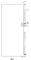
- Figure 1 is a front view of an appliance according to one embodiment of the present invention.
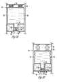
- Figure 2 is a partial cross-sectional side view of the appliance including a liquid dispenser with a collapsible container according to one embodiment of the present invention.
- Figure 3A is a cross-sectional detail view of a liquid dispenser that includes a collapsible container and a moveable member for estimating an amount of liquid remaining in the container.
- Figure 3B is a detail cross-section view of a liquid container of Figure 3A indicating a smaller amount of liquid remaining within the collapsible container.
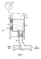
- Figure 4 is a partial cross-section detail view of a liquid dispenser including a collapsible container and a mechanism for estimating the liquid remaining in the collapsible container according to another embodiment of the present invention.
- Figure 5 is a perspective view of an embodiment of a collapsible container for use in the present invention.
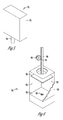
- Figure 6 is a cut-away perspective view of a chamber according to one embodiment of the present invention for use in estimating the amount of liquid remaining within a collapsible container and for clearing any clogs within a valve attached to the collapsible container.
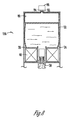
- Figure 7A shows a cross-sectional view of the chamber of Figure 6 with a full collapsible container in place within the chamber.
- Figure 7B is a cross-sectional view of the chamber of Figure 7A while the dispenser is dispensing liquid.
- Figure 8 is a partial cross-sectional detail view of a liquid dispenser for dispensing liquid from a collapsible container wherein the dispenser includes a bladder for pressing against the collapsible container.
- FIG. 1 is a front elevation view of an appliance 10 according to one embodiment of the present invention that includes a liquid dispenser.
- the appliance 10 is a household refrigerator.
- appliance 10 may be any household appliance that includes a liquid dispenser that utilizes a collapsible container for containing the supply of liquid.
- the appliance 10 might be a beverage dispenser that utilizes a collapsible container containing flavorant for providing flavored beverages.
- the appliance 10 might be a dishwasher that utilizes a collapsible container containing dishwashing soap.
- Appliance 10 might be a clothes washing machine that utilizes a collapsible container containing laundry detergent.
- the refrigerator 10 of Figure 1 has a dispenser housing 12 mounted on a refrigerator door 14. Control buttons 16 are provided to permit control of various functions of the dispenser.
- a liquid gauge 18 indicates an estimated volume of liquid remaining in the collapsible container.
- the liquid gauge 18 is shown as a vertical gauge with a full indicator at the top of the gauge and an empty indicator at the bottom of the gauge.
- the gauge 18 might also be a dial style gauge, or could be a digital output.
- a dispenser outlet 20 provides an outlet through which a beverage can be dispensed.
- the outlet 20 may include one or more nozzles for dispensing water and flavorant.
- the outlet 20 may also include an outlet for dispensing ice.
- FIG. 2 shows a cross-sectional view of the door 14 of the appliance 10.
- a collapsible container 22 is provided within a chamber 24 formed in the door 14.
- the collapsible container 22 will preferably contain a concentrated flavorant that can be mixed with water to form a flavored beverage.
- the collapsible container 22 might contain a pre-mixed beverage that does not need to be diluted with water.
- the collapsible container 22 rests against a stationary bottom wall 26.
- a moveable member 28 is in contact with the top of the collapsible container 22. As the amount of liquid remaining within the collapsible container 22 reduces, the top of the collapsible container 22 will collapse towards the stationary bottom wall 26.
- the moveable member 28 is held in contact with the top of the collapsible container 22 by biasing elements 30. Therefore when the collapsible container 22 is full, the moveable member 28 is located near the top chamber 24. As liquid is removed from the collapsible container 22 and the collapsible container 22 collapses downwardly towards the stationary bottom wall 26, the moveable member 28 also moves downward towards the stationary bottom wall 26. A portion of the moveable member 28 is visible to users, such that users receive a visual indication of approximately how much liquid is remaining in the collapsible container 22.
- the biasing elements 30 may be something simple such as springs or other resilient members, or may be more complicated structures, such as a motor or motors or solenoids.
- the collapsible container 22 may be associated with a pump and valve mechanism 32 for controlling the dispensing of liquid from the collapsible container 22.
- the pump and valve mechanism 32 includes an outlet spout 34 that is affixed to the collapsible container 22.
- the outlet spout 34 is open to receive liquid from the collapsible container 22 in an upper end of the outlet spout 34.
- At a lower end of the outlet spout 34 is an outlet aperture 36.
- the outlet aperture 36 is normally closed by valve head 38.
- a valve rod 40 extends through the outlet aperture 36 and connects the valve head 38 with a pump head 42.
- the valve head 38 is retained in the closed position that seals outlet aperture 36 by a spring 44 that presses between shoulder 46 and the pump head 42.
- Either the pump head 42 or the valve rod 44, or both, may be formed from a ferrous material.
- a magnetic field generator 48 surrounds the outlet spout 34.
- the magnetic field generator 48 may be an electric coil.
- the magnetic field generator 48 is activated, such as by passing an electric current through an electric coil, the magnetic force generated will cause the pump head 42 and rod 40 to be pulled downwardly such that the valve head 38 is unseated from the shoulder 46 to permit the liquid 50 within the collapsible container 22 to flow outwardly through the outlet aperture 36.
- the moveable member 28 rests on top of the collapsible container 22. A portion of the moveable member 28 is visible outside of the chamber 26, such that it acts as a volume indicator 52.
- the collapsible container 22 is full, or nearly full, of liquid 50. Accordingly, the moveable member 28, which sits on top of the collapsible container 22, is near the top of the chamber 26, such that the volume indicator 52 is at the top of the liquid gauge 18 to indicate to a user that the collapsible container 22 is nearly full.
- Figure 3B some of the liquid 50 has been dispensed from the collapsible container 22, such that the collapsible container 22 is only partially full.
- the moveable member 28, which rests on top of the collapsible container 22, has been lowered towards the stationary wall 26 of the bottom of the chamber 24.
- the volume indicator 52 is therefore at an intermediate position within the liquid gauge 18 indicating that the collapsible container 22 is partially filled with liquid 50, permitting a user to estimate about how much liquid remains.
- the springs 30, which act as biasing elements, retain the moveable member 28 in close contact with the top of the collapsible container 22, such that as the collapsible container 22 empties, the moveable member 28 remains in contact with the collapsible container 22.
- the pump and valve mechanism 32 shown in Figures 3A and 3B is of the same type as shown and described in Greenwald, U.S. Patent No. 7,578,419 ; Girard, U.S. Patent Publication No. 2006/0000851 ; and Girard, U. S. Patent Publication No. 2008/0173705 ; all of which are hereby incorporated by reference in their entireties.
- Those of skill in the art may be aware of other valve and pump mechanisms that can be used to dispense liquid from a collapsible container in order to take advantage of the present invention.
- the present invention would be beneficially used with collapsible containers that rely on gravity flow or pressurizing of the container, rather than a pump mechanism.
- FIG. 4 shows an embodiment of an appliance liquid dispenser 56 according to another embodiment of the present invention.
- the appliance liquid dispenser 56 includes a chamber 24 with a stationary side wall 26.
- a moveable member 28 is provided that is biased towards the stationary wall 26 by biasing elements 30.
- the biasing elements 30 maintain the moveable member 28 in contact with a side of the collapsible container 22 that is opposite from the stationary wall 26.
- the moveable member 28 approaches the stationary wall 26.
- the moveable member 28 is associated with a gauge 18 that indicates an estimated amount of liquid remaining in the collapsible container 22.
- the appliance dispenser 56 of Figure 4 is provided with an outlet conduit 68 that connects with a dispenser conduit 70.
- the dispenser conduit 70 is connected with a water conduit 72. Therefore, the liquid 50 within the collapsible container may be mixed with the water in the water conduit 72 to be dispensed from the dispenser conduit 70 as a mixture.
- the mixture may be a flavored beverage, or may be a mixture of soap and water.
- the water conduit 72 is provided with a valve 74 for selectively controlling the flow of water.
- FIG. 5 shows an isometric view of a disposable cartridge 54 that is suitable for use within the present invention.
- the disposable cartridge 54 includes a collapsible container portion 22 that is sealed in fluid communication with an outlet spout 34.
- FIG. 6 shows an appliance liquid dispenser 56 in which the disposable cartridge 54 may be used.
- the appliance liquid dispense 56 includes a chamber 24 formed by side walls 58.
- a stationary bottom wall 26 includes an opening 60 for receiving the outlet spout 34 of the disposable cartridge 54 when it is inserted into the chamber 24 in a working position.
- a moveable member 28, in the form of a plate, is attached to a rack 62.
- the rack 62 is moveable up and down by a pinion gear 64 that is driven by a motor or similar device. Therefore, the motor, pinion gear 64, and rack 62 acts together as a biasing element to bias the moveable member 28 up and down.
- FIGs 7A and 7B show the appliance liquid dispenser 56 from Figure 6 in cross-sectional view with a disposable cartridge 54 inserted.
- the collapsible container 22 of the disposable cartridge 54 is full.
- the moveable member 28 is near the top of the chamber 24.
- the rack 62 is lifted to nearly its highest position.
- the rack 62 itself may serve as a visual indicator of the volume of liquid remaining within the container 22.
- a position sensor may be utilized in conjunction with the rack 62 or the moveable member 28 to send a signal to a gauge 18 that indicates approximately how much liquid remains in the collapsible container 22 dependent upon the position of the rack 62 or the moveable member 28.
- a sensor may be connected with the pinion gear 64 to sense an angular position of the pinion gear and thereby sense the position of the moveable plates 28, which a proxy for the amount of liquid remaining within the collapsible container 22.
- the pump and valve mechanism is similar to that shown in Figures 3A and 3B .
- liquid can dry and harden at the interface between the valve head 38 and the shoulder 46. This causes the valve head 38 to adhere to the shoulder 46 which can form a clog or blockage of the outlet aperture 36.
- the biasing mechanism in the case of Figures 7A and 7B , the rack and pinion 62 and 64, can be activated to move the moveable member 28 towards the stationary bottom wall 26 in order to squeeze the collapsible container 22 between the moveable member 28 and the stationary bottom wall 26.
- This squeezing of the collapsible container 22 increases the liquid pressure within the collapsible container 22, which thereby pushes outward against the valve head 38 which tends to break the valve head 38 free from the shoulder 46.
- Those of ordinary skill in the art will be aware of other biasing mechanisms for applying a force to the moveable member 28 to thereby increase the pressure within the collapsible container 22 to help resolve any blockage of the outlet aperture 36. It may be necessary to apply the squeezing force only at the initiation of a dispensing cycle in order to resolve any blockages.
- the actual dispensing of liquid through the outlet aperture is primarily accomplished by sequentially activating the magnetic field generator 48 causing the valve rod 40 and pump head 42 to reciprocate up and down in order to pump liquid through the outlet aperture 36.
- FIG 7B the magnetic field generator 48 has been activated, causing the valve rod 40 and pump head 42 to be pulled downwardly to open the outlet aperture 36 and cause liquid to be dispensed from the collapsible container 22.
- the collapsible container 22 has been partially emptied, and therefore the top of the collapsible container 22 has collapsed towards the bottom stationary wall 26.
- the moveable member 28 is maintained in contact with the top of the collapsible container 22 by the biasing mechanism of the motor 66 and pinion gear 64 acting against the rack 62.
- the amount of liquid remaining within the collapsible container 22 can then be estimated by an inspection of the position of the rack 62.
- a position sensor may be associated with the rack 62 or the moveable member 28 to provide a signal to a gauge based on the position of the moveable member 28.
- the embodiment shown in Figures 6 and 7A-7B is adapted to use the moveable member 28 both to help resolve clogs, and to estimate the amount of liquid remaining within the collapsible container 22.
- FIG 8 shows an embodiment of an appliance liquid dispenser 156 according to another embodiment of the present invention.
- an inflatable bladder 80 is used to press against the collapsible container 22, as seen in Figure 8 .
- the collapsible container 22 is provided within a chamber 24 formed within an appliance that includes at least one stationary wall 26.
- the inflatable bladder 80 is also provided within the chamber 24 such that as the bladder 80 is inflated, for example with air or other gas, it squeezes the collapsible container 22 against stationary wall 26.
- the bladder 80 contains a constant amount of gas within it. Therefore, the pressure and temperature of the gas within the bladder 80 can be measured to estimate a volume occupied by the gas in the bladder, which is directly related to the amount of liquid remaining within collapsible container 22.
- a pressure transducer 82 and temperature sensor 84 may be included in this embodiment.
- the temperature of the bladder 80 may remain relatively constant, such that it is unnecessary to include a temperature sensor.
- the sensors (82 and 84) may be connected with a processor that utilizes signals received from the sensors 82 and 84 to calculate an estimated amount of liquid remaining in the collapsible container 22. The processor can then send a signal to a gauge that displays an indication of the amount of liquid remaining.
- the dispenser 156 may also be provided both on pump 86 in order to pressurize gas from the bladder 80.
- the pump 86 may be energized to pressurize the bladder 80 upon the initiation of a dispensing cycle in order to pressurize the liquid within the collapsible container 22 to provide an additional force against the valve head 38 that urges the valve head 38 to the open configuration shown in Figure 8 , in order to help resolve any clogs at the initiation of the dispensing cycle.
- a release valve (not shown) may also be provided to release gas and reduce pressure in the bladder 80.
Landscapes
- Engineering & Computer Science (AREA)
- Chemical & Material Sciences (AREA)
- Combustion & Propulsion (AREA)
- Physics & Mathematics (AREA)
- Mechanical Engineering (AREA)
- Thermal Sciences (AREA)
- General Engineering & Computer Science (AREA)
- Devices For Dispensing Beverages (AREA)
- Containers And Packaging Bodies Having A Special Means To Remove Contents (AREA)
Applications Claiming Priority (1)
| Application Number | Priority Date | Filing Date | Title |
|---|---|---|---|
| US12/915,081 US9534831B2 (en) | 2010-10-29 | 2010-10-29 | Liquid dispenser with collapsible container |
Publications (1)
| Publication Number | Publication Date |
|---|---|
| EP2447640A2 true EP2447640A2 (de) | 2012-05-02 |
Family
ID=44862680
Family Applications (1)
| Application Number | Title | Priority Date | Filing Date |
|---|---|---|---|
| EP11186537A Withdrawn EP2447640A2 (de) | 2010-10-29 | 2011-10-25 | Flüssigkeitsausgabe mit zusammenklappbarem Behälter |
Country Status (3)
| Country | Link |
|---|---|
| US (1) | US9534831B2 (de) |
| EP (1) | EP2447640A2 (de) |
| BR (1) | BRPI1106888A2 (de) |
Cited By (3)
| Publication number | Priority date | Publication date | Assignee | Title |
|---|---|---|---|---|
| CN104754999A (zh) * | 2012-10-25 | 2015-07-01 | Sca卫生用品公司 | 带有用于检测液位的装置的分配系统和用于这种系统的可收缩容器 |
| WO2017176137A1 (pt) * | 2016-04-07 | 2017-10-12 | Novadelta - Comércio E Indústria De Cafés, S.A. | Máquina e processo de preparação de bebidas com disposição de cartuchos de concentrado de bebida |
| EP3832000A1 (de) * | 2019-12-03 | 2021-06-09 | Whirlpool Corporation | System für abgabe von waschmittel |
Families Citing this family (25)
| Publication number | Priority date | Publication date | Assignee | Title |
|---|---|---|---|---|
| US20170015545A1 (en) * | 2011-02-10 | 2017-01-19 | Pack Flow Concepts Llc | Refillable container with a zero waste dispensing system |
| US9821996B2 (en) | 2012-02-17 | 2017-11-21 | Gus J. Stratton | Beverage dispensing apparatus and method |
| US9365405B2 (en) | 2012-02-17 | 2016-06-14 | Gus Stratton | Beverage dispensing system |
| DE102012101507A1 (de) * | 2012-02-24 | 2013-08-29 | Krones Aktiengesellschaft | Zapfanlage mit gesteuerter Flüssigkeitsausgabe |
| DE102012111850A1 (de) * | 2012-12-05 | 2014-06-05 | Krones Ag | Vorrichtung zum Entleeren von Behältnissen |
| DE102012111845A1 (de) * | 2012-12-05 | 2014-06-05 | Krones Ag | Vorrichtung zum Entnehmen von Flüssigkeiten aus Behältnissen |
| EP2808628B1 (de) * | 2013-05-28 | 2016-07-20 | LG Electronics Inc. | Gemüsebehälter für Kühlschränke und Kühlschrank damit |
| DE102013212809A1 (de) * | 2013-07-01 | 2015-01-08 | Brainlink Gmbh | Getränkezubereitungssystem mit Einwegbehälter |
| WO2015021015A1 (en) | 2013-08-05 | 2015-02-12 | Johns Nicholas P | Method and apparatus for delivering fluid to an individual |
| DE102013109265A1 (de) * | 2013-08-27 | 2015-03-05 | Krones Ag | Vorrichtung und Verfahren zum Entleeren von Behältnissen mit Steuerung eines Antriebsdrehmomentes |
| DE102013110121A1 (de) * | 2013-09-13 | 2015-03-19 | Krones Ag | Einwegentleerungssystem für Behältnisse |
| CN105683059A (zh) * | 2013-11-06 | 2016-06-15 | 宝洁公司 | 具有产品体积和联接到其的支座结构的容器 |
| US9723942B2 (en) | 2014-06-21 | 2017-08-08 | Palm Coffeemaker LLC | Brewing and filtering device for coffee and tea |
| US10264926B2 (en) * | 2015-02-04 | 2019-04-23 | Gojo Industries, Inc. | Collapsible liquid container, fluid dispenser for collapsible liquid container, and method for making collapsible liquid container |
| US9896253B2 (en) | 2015-04-10 | 2018-02-20 | The Procter & Gamble Company | Flexible containers with reinforcing seals |
| US20160332754A1 (en) * | 2015-05-13 | 2016-11-17 | Fontem Holdings 4 B.V. | Device for refilling electronic cigarette cartridge |
| JP6822897B2 (ja) * | 2017-05-19 | 2021-01-27 | サンデン・リテールシステム株式会社 | 飲料供給装置 |
| CN111197693B (zh) * | 2018-11-16 | 2021-11-26 | 英业达科技有限公司 | 储气装置 |
| US11198142B2 (en) * | 2019-01-18 | 2021-12-14 | Rooftop Research, Llc | Fluid dispensing system |
| US11052625B2 (en) * | 2019-10-30 | 2021-07-06 | Fresh Press LLC | Hydraulic press for food items |
| US20230049594A1 (en) * | 2021-08-13 | 2023-02-16 | Peter Gombrich | Fluid dispenser comprising refillable disposable bag and a means for flow control |
| US11434122B1 (en) * | 2021-12-10 | 2022-09-06 | Cana Technology, Inc. | Dispense system for a fluid mixture dispensing device |
| US20240002207A1 (en) * | 2022-07-01 | 2024-01-04 | Starbucks Corporation | Fluid dispenser |
| US20240294306A1 (en) * | 2023-03-03 | 2024-09-05 | Davis Food, Llc | Dispenser for products in a flexible tube |
| CN118189499B (zh) * | 2024-05-20 | 2024-07-09 | 济南大森制冷科技有限公司 | 一种超低温制冷系统装置 |
Citations (3)
| Publication number | Priority date | Publication date | Assignee | Title |
|---|---|---|---|---|
| US20060000851A1 (en) | 2004-02-13 | 2006-01-05 | Intelligent Coffee Company, Llc | Liquid concentrate/extract beverage dispenser with replaceable concentrate/extract cartridge |
| US20080173705A1 (en) | 2004-02-13 | 2008-07-24 | Intelligent Coffee Company, Llc | Liquid dispensing system |
| US7578419B2 (en) | 2005-01-07 | 2009-08-25 | Greenwald Technologies, Llc | Disposable integrated bag and pump |
Family Cites Families (47)
| Publication number | Priority date | Publication date | Assignee | Title |
|---|---|---|---|---|
| US720902A (en) * | 1902-11-05 | 1903-02-17 | Herman Du Brau | Apparatus for making relief-work. |
| US2229850A (en) * | 1939-02-20 | 1941-01-28 | Truan T Lester | Water cooler |
| US2408704A (en) * | 1944-05-04 | 1946-10-01 | George R Taylor | Liquid cooler for refrigerators |
| US2437589A (en) * | 1945-04-23 | 1948-03-09 | Arthur R Bink | Telescoping dispensing nozzle with fluid pressure-operated safety valve |
| US2659517A (en) * | 1951-09-21 | 1953-11-17 | Jr Carl H Reinhardt | Paste type products container and dispenser therefor having a cutter-valve for opening the container |
| US2970452A (en) * | 1959-04-01 | 1961-02-07 | Union Carbide Corp | Method and apparatus for supplying liquefied gas |
| US3734348A (en) * | 1971-09-23 | 1973-05-22 | Us Air Force | Method of expelling liquid propellant from a storage tank in a liquid rocket |
| US4386716A (en) | 1978-02-23 | 1983-06-07 | Becton Dickinson And Company | Liquid measuring device |
| US4509659A (en) * | 1982-09-08 | 1985-04-09 | Richard Cloutier | Portable liquid measuring and dispensing device |
| US4645094A (en) * | 1983-04-26 | 1987-02-24 | Calgon Corporation | Photo-electric controlled dispenser |
| DE3761205D1 (de) * | 1986-03-10 | 1990-01-25 | Solly Katz | Ausgeber fuer fluessigkeiten. |
| US4711373A (en) * | 1986-04-10 | 1987-12-08 | Trinity Foundation | Portable dispensing system |
| US5620115A (en) * | 1987-12-10 | 1997-04-15 | Mcgill; Shane R. | Confection dispensing apparatus |
| US4886189A (en) * | 1988-02-29 | 1989-12-12 | Vanderjagt John A | System for selectively containing metering and dispensing liquids |
| US5158793A (en) * | 1988-07-12 | 1992-10-27 | Edward Helbling | Coffee machine with product selectivity |
| US5048724A (en) * | 1988-11-22 | 1991-09-17 | Fedpak Systems, Inc. | Soft serve frozen confection dispenser |
| JP2547636B2 (ja) * | 1989-07-14 | 1996-10-23 | テルモ株式会社 | 液体分離装置 |
| US5145083A (en) * | 1989-08-28 | 1992-09-08 | Kirin Beer Kabushiki Kaisha | Cap device for mouthpiece of container and methods of sealing mouthpiece portion of container and opening the same |
| US5046648A (en) * | 1990-01-02 | 1991-09-10 | Herbstzuber Remedios E | Hygienic dispenser |
| US5377871A (en) * | 1993-01-04 | 1995-01-03 | Marlingford Holdings Limited | Dispenser having roller for dispensing fluid from a collapsible bag |
| US5499758A (en) * | 1994-08-19 | 1996-03-19 | Mccann's Engineering & Manufacturing Co. | Liquid dispenser for use with containers |
| US5603230A (en) * | 1996-04-18 | 1997-02-18 | Tsai; Te-Wan | Water supply device for a refrigerator door |
| US6131766A (en) * | 1996-08-12 | 2000-10-17 | Restaurant Automation Development Inc. | System for dispensing controlled amounts of flowable material from a flexible container |
| FR2773543B1 (fr) * | 1998-01-14 | 2000-02-18 | Oreal | Ensemble de conditionnement et de distribution sous pression, a mise sous pression extemporanee |
| US5992685A (en) * | 1998-01-23 | 1999-11-30 | The Coca-Cola Company | Fountain dispensing module |
| US6138693A (en) * | 1998-11-23 | 2000-10-31 | Matz; Warren W. | Automatic detergent dispenser |
| US6264066B1 (en) * | 1999-07-15 | 2001-07-24 | Grand Soft Equipment Co. | Apparatus and method for dispensing a desired portion of frozen product |
| TW550179B (en) * | 2000-12-01 | 2003-09-01 | Int United Technology Co Ltd | Ink cartridge with retaining tab to retain pressure regulating mechanism |
| TW503186B (en) * | 2001-02-02 | 2002-09-21 | Benq Corp | Detecting device for ink storage |
| US6741180B2 (en) * | 2001-03-26 | 2004-05-25 | Food Equipment Technologies Company, Inc. | Beverage dispensing URN with electronic display |
| US7150791B2 (en) | 2001-03-29 | 2006-12-19 | Nordson Corporation | Floating head liquid dispenser with dispensing head sensor |
| US6401977B1 (en) * | 2001-06-29 | 2002-06-11 | Ross, Iii Garrison A. | Toothpaste extracting device |
| US6739478B2 (en) | 2001-06-29 | 2004-05-25 | Scientific Products & Systems Llc | Precision fluid dispensing system |
| US20040067394A1 (en) * | 2002-09-30 | 2004-04-08 | Kabushiki Kaisha Toshiba | Liquid cartridge |
| US6926170B2 (en) * | 2002-12-12 | 2005-08-09 | R. Clay Groesbeck | Drink dispensing cart and water packaging and supply system |
| US7744817B2 (en) | 2003-08-11 | 2010-06-29 | Sakura Finetek U.S.A., Inc. | Manifold assembly |
| US7086568B1 (en) * | 2003-08-15 | 2006-08-08 | Everett Cheek | Toothpaste dispenser |
| US7350423B2 (en) | 2004-01-14 | 2008-04-01 | International Business Machines Corporation | Real time usage monitor and method for detecting entrapped air |
| US7651015B2 (en) | 2004-02-13 | 2010-01-26 | Intelligent Coffee Company, Llc | Liquid concentrate/extract beverage dispenser with replaceable concentrate/extract cartridge |
| US20060264829A1 (en) * | 2005-05-10 | 2006-11-23 | Par Technologies, Llc | Disposable fluid container with integrated pump motive assembly |
| ATE546715T1 (de) | 2005-11-03 | 2012-03-15 | Intelligent Coffee Company L L C | Flüssigkeitskonzentrat-/-extrakt-getränkespende mit austauschbarer konzentrat/extrakt-patrone |
| US20100059544A1 (en) * | 2006-09-18 | 2010-03-11 | Koninklijke Philips Electronics N.V. | Keg enveloping a container for containing a pressurized beverage |
| US7694849B1 (en) * | 2006-12-11 | 2010-04-13 | Turnout Products, Inc. | Product dispenser with crankable assembly |
| US20090112149A1 (en) * | 2007-10-31 | 2009-04-30 | Kriesel Marshall S | Variable rate fluid dispenser |
| US20120074167A1 (en) * | 2010-09-27 | 2012-03-29 | Adco Products, Inc. | Adhesive package |
| US9505600B2 (en) * | 2013-11-13 | 2016-11-29 | TRV Dispense, LLC | Soft food and beverage dispenser |
| CN107207233B (zh) * | 2014-09-08 | 2019-12-17 | 格绕乐威客股份公司 | 饮料分配器 |
-
2010
- 2010-10-29 US US12/915,081 patent/US9534831B2/en active Active
-
2011
- 2011-10-25 EP EP11186537A patent/EP2447640A2/de not_active Withdrawn
- 2011-10-27 BR BRPI1106888-4A patent/BRPI1106888A2/pt not_active Application Discontinuation
Patent Citations (4)
| Publication number | Priority date | Publication date | Assignee | Title |
|---|---|---|---|---|
| US20060000851A1 (en) | 2004-02-13 | 2006-01-05 | Intelligent Coffee Company, Llc | Liquid concentrate/extract beverage dispenser with replaceable concentrate/extract cartridge |
| US20060016347A1 (en) | 2004-02-13 | 2006-01-26 | Intelligent Coffee Company, Llc | Replaceable concentrate/extract cartridge for a liquid concentrate/extract beverage dispenser |
| US20080173705A1 (en) | 2004-02-13 | 2008-07-24 | Intelligent Coffee Company, Llc | Liquid dispensing system |
| US7578419B2 (en) | 2005-01-07 | 2009-08-25 | Greenwald Technologies, Llc | Disposable integrated bag and pump |
Cited By (10)
| Publication number | Priority date | Publication date | Assignee | Title |
|---|---|---|---|---|
| CN104754999A (zh) * | 2012-10-25 | 2015-07-01 | Sca卫生用品公司 | 带有用于检测液位的装置的分配系统和用于这种系统的可收缩容器 |
| EP2911562A4 (de) * | 2012-10-25 | 2016-07-06 | Sca Hygiene Prod Ab | Ausgabesystem mit vorrichtung zur flüssigkeitsstandmessung und zusammenklappbarer behälter für solch ein system |
| US9586728B2 (en) | 2012-10-25 | 2017-03-07 | Sca Hygiene Products Ab | Dispensing system with the means for detecting liquid level and a collapsible container for such a system |
| CN104754999B (zh) * | 2012-10-25 | 2018-02-09 | Sca卫生用品公司 | 带有用于检测液位的装置的分配系统和用于这种系统的可收缩容器 |
| WO2017176137A1 (pt) * | 2016-04-07 | 2017-10-12 | Novadelta - Comércio E Indústria De Cafés, S.A. | Máquina e processo de preparação de bebidas com disposição de cartuchos de concentrado de bebida |
| CN109195902A (zh) * | 2016-04-07 | 2019-01-11 | 诺威德尔塔咖啡贸易工业有限公司 | 用饮料浓缩物筒制备饮料的机器和方法 |
| CN109195902B (zh) * | 2016-04-07 | 2020-11-06 | 诺威德尔塔咖啡贸易工业有限公司 | 用饮料浓缩物筒制备饮料的机器和方法 |
| US11197575B2 (en) | 2016-04-07 | 2021-12-14 | Novadelta—Comércio E Indústria De Cafés S.A. | Machine for preparing beverages with beverage concentrate cartridges |
| EP3832000A1 (de) * | 2019-12-03 | 2021-06-09 | Whirlpool Corporation | System für abgabe von waschmittel |
| US12123126B2 (en) | 2019-12-03 | 2024-10-22 | Whirlpool Corporation | System for laundry detergent delivery |
Also Published As
| Publication number | Publication date |
|---|---|
| BRPI1106888A2 (pt) | 2013-03-26 |
| US9534831B2 (en) | 2017-01-03 |
| US20120104020A1 (en) | 2012-05-03 |
Similar Documents
| Publication | Publication Date | Title |
|---|---|---|
| US9534831B2 (en) | Liquid dispenser with collapsible container | |
| AU2022246451B2 (en) | Coffee maker | |
| US7896202B2 (en) | Disposable integrated bag and pump | |
| KR101307725B1 (ko) | 음료 생성 기계를 위한 배수 | |
| US7578419B2 (en) | Disposable integrated bag and pump | |
| EP2141275B1 (de) | Verfahren und Vorrichtung zur Anzeige von Betriebsinformation für ein Ausgabesystem mit Einzel- und Mehrfachausgabe | |
| US8663724B1 (en) | Automated beverage brewing method | |
| KR101651260B1 (ko) | 유체 전달 시스템 | |
| EP2447206A2 (de) | Getränkeautomat mit Mehrfachkammer-Karussell und automatische Koordinierung der Geschmacksmittelflussrate | |
| JP2013544601A (ja) | 飲料機の為の簡単なユーザー・インターフェース | |
| CN115010078A (zh) | 饮料分配系统及清洗饮料分配系统的方法 | |
| US20230190032A1 (en) | Beverage Machine Using Pods that Contain Whole Brewing Elements | |
| EP3619145A1 (de) | Getränkemaschine mit kapseln, die ganze brauelemente enthalten | |
| CN101080358B (zh) | 制备适于消费的饮料的系统和方法 | |
| US8499980B2 (en) | Dispenser for a flowable medium having a valved removable container for receiving an exchangeable reservoir | |
| WO2003023120A1 (en) | An automatic washing agent dosing device | |
| JP7419363B2 (ja) | 食用製品を受領容器に前記受領容器によって調節された状態において分配するシステム及びプロセス | |
| KR101769965B1 (ko) | 액상생활용품을 자동/수동으로 토출하는 디스펜서 | |
| JP2005152188A (ja) | 飲料抽出機 | |
| RU2776740C1 (ru) | Система и способ распределения пищевых продуктов в приемный элемент, регулируемые посредством указанного приемного элемента | |
| EP0659378A1 (de) | Maschine zum Bereiten von heissen Infusionsgetränken | |
| JP4558844B1 (ja) | 液体ディスペンサー | |
| JP2005087357A (ja) | 飲料抽出機 |
Legal Events
| Date | Code | Title | Description |
|---|---|---|---|
| PUAI | Public reference made under article 153(3) epc to a published international application that has entered the european phase |
Free format text: ORIGINAL CODE: 0009012 |
|
| AK | Designated contracting states |
Kind code of ref document: A2 Designated state(s): AL AT BE BG CH CY CZ DE DK EE ES FI FR GB GR HR HU IE IS IT LI LT LU LV MC MK MT NL NO PL PT RO RS SE SI SK SM TR |
|
| AX | Request for extension of the european patent |
Extension state: BA ME |
|
| STAA | Information on the status of an ep patent application or granted ep patent |
Free format text: STATUS: THE APPLICATION HAS BEEN WITHDRAWN |
|
| 18W | Application withdrawn |
Effective date: 20141014 |