EP2447545B1 - Hochdruckverstärker - Google Patents
Hochdruckverstärker Download PDFInfo
- Publication number
- EP2447545B1 EP2447545B1 EP10189641.3A EP10189641A EP2447545B1 EP 2447545 B1 EP2447545 B1 EP 2447545B1 EP 10189641 A EP10189641 A EP 10189641A EP 2447545 B1 EP2447545 B1 EP 2447545B1
- Authority
- EP
- European Patent Office
- Prior art keywords
- low pressure
- pressure side
- high pressure
- piston
- pistons
- Prior art date
- Legal status (The legal status is an assumption and is not a legal conclusion. Google has not performed a legal analysis and makes no representation as to the accuracy of the status listed.)
- Active
Links
- 239000012530 fluid Substances 0.000 claims description 42
- 230000008878 coupling Effects 0.000 claims description 16
- 238000010168 coupling process Methods 0.000 claims description 16
- 238000005859 coupling reaction Methods 0.000 claims description 16
- 238000000034 method Methods 0.000 claims description 4
- 230000009471 action Effects 0.000 description 5
- 238000004891 communication Methods 0.000 description 4
- 238000004519 manufacturing process Methods 0.000 description 2
- 238000005086 pumping Methods 0.000 description 2
- 230000006872 improvement Effects 0.000 description 1
- 239000003129 oil well Substances 0.000 description 1
Images

Classifications
-
- F—MECHANICAL ENGINEERING; LIGHTING; HEATING; WEAPONS; BLASTING
- F15—FLUID-PRESSURE ACTUATORS; HYDRAULICS OR PNEUMATICS IN GENERAL
- F15B—SYSTEMS ACTING BY MEANS OF FLUIDS IN GENERAL; FLUID-PRESSURE ACTUATORS, e.g. SERVOMOTORS; DETAILS OF FLUID-PRESSURE SYSTEMS, NOT OTHERWISE PROVIDED FOR
- F15B3/00—Intensifiers or fluid-pressure converters, e.g. pressure exchangers; Conveying pressure from one fluid system to another, without contact between the fluids
-
- E—FIXED CONSTRUCTIONS
- E21—EARTH DRILLING; MINING
- E21B—EARTH DRILLING, e.g. DEEP DRILLING; OBTAINING OIL, GAS, WATER, SOLUBLE OR MELTABLE MATERIALS OR A SLURRY OF MINERALS FROM WELLS
- E21B33/00—Sealing or packing boreholes or wells
- E21B33/02—Surface sealing or packing
- E21B33/03—Well heads; Setting-up thereof
- E21B33/035—Well heads; Setting-up thereof specially adapted for underwater installations
- E21B33/0355—Control systems, e.g. hydraulic, pneumatic, electric, acoustic, for submerged well heads
-
- F—MECHANICAL ENGINEERING; LIGHTING; HEATING; WEAPONS; BLASTING
- F04—POSITIVE - DISPLACEMENT MACHINES FOR LIQUIDS; PUMPS FOR LIQUIDS OR ELASTIC FLUIDS
- F04B—POSITIVE-DISPLACEMENT MACHINES FOR LIQUIDS; PUMPS
- F04B49/00—Control, e.g. of pump delivery, or pump pressure of, or safety measures for, machines, pumps, or pumping installations, not otherwise provided for, or of interest apart from, groups F04B1/00 - F04B47/00
- F04B49/06—Control using electricity
-
- F—MECHANICAL ENGINEERING; LIGHTING; HEATING; WEAPONS; BLASTING
- F04—POSITIVE - DISPLACEMENT MACHINES FOR LIQUIDS; PUMPS FOR LIQUIDS OR ELASTIC FLUIDS
- F04B—POSITIVE-DISPLACEMENT MACHINES FOR LIQUIDS; PUMPS
- F04B9/00—Piston machines or pumps characterised by the driving or driven means to or from their working members
- F04B9/08—Piston machines or pumps characterised by the driving or driven means to or from their working members the means being fluid
- F04B9/10—Piston machines or pumps characterised by the driving or driven means to or from their working members the means being fluid the fluid being liquid
- F04B9/109—Piston machines or pumps characterised by the driving or driven means to or from their working members the means being fluid the fluid being liquid having plural pumping chambers
- F04B9/1095—Piston machines or pumps characterised by the driving or driven means to or from their working members the means being fluid the fluid being liquid having plural pumping chambers having two or more pumping chambers in series
-
- F—MECHANICAL ENGINEERING; LIGHTING; HEATING; WEAPONS; BLASTING
- F04—POSITIVE - DISPLACEMENT MACHINES FOR LIQUIDS; PUMPS FOR LIQUIDS OR ELASTIC FLUIDS
- F04B—POSITIVE-DISPLACEMENT MACHINES FOR LIQUIDS; PUMPS
- F04B9/00—Piston machines or pumps characterised by the driving or driven means to or from their working members
- F04B9/08—Piston machines or pumps characterised by the driving or driven means to or from their working members the means being fluid
- F04B9/10—Piston machines or pumps characterised by the driving or driven means to or from their working members the means being fluid the fluid being liquid
- F04B9/109—Piston machines or pumps characterised by the driving or driven means to or from their working members the means being fluid the fluid being liquid having plural pumping chambers
- F04B9/111—Piston machines or pumps characterised by the driving or driven means to or from their working members the means being fluid the fluid being liquid having plural pumping chambers with two mechanically connected pumping members
- F04B9/115—Piston machines or pumps characterised by the driving or driven means to or from their working members the means being fluid the fluid being liquid having plural pumping chambers with two mechanically connected pumping members reciprocating movement of the pumping members being obtained by two single-acting liquid motors, each acting in one direction
-
- F—MECHANICAL ENGINEERING; LIGHTING; HEATING; WEAPONS; BLASTING
- F15—FLUID-PRESSURE ACTUATORS; HYDRAULICS OR PNEUMATICS IN GENERAL
- F15B—SYSTEMS ACTING BY MEANS OF FLUIDS IN GENERAL; FLUID-PRESSURE ACTUATORS, e.g. SERVOMOTORS; DETAILS OF FLUID-PRESSURE SYSTEMS, NOT OTHERWISE PROVIDED FOR
- F15B9/00—Servomotors with follow-up action, e.g. obtained by feed-back control, i.e. in which the position of the actuated member conforms with that of the controlling member
- F15B9/02—Servomotors with follow-up action, e.g. obtained by feed-back control, i.e. in which the position of the actuated member conforms with that of the controlling member with servomotors of the reciprocatable or oscillatable type
- F15B9/03—Servomotors with follow-up action, e.g. obtained by feed-back control, i.e. in which the position of the actuated member conforms with that of the controlling member with servomotors of the reciprocatable or oscillatable type with electrical control means
Definitions
- the present invention relates to high pressure intensifiers.
- subsea trees require few high pressure valve functions.
- SSSV subsea safety valve
- This valve requires a source of high pressure hydraulic fluid at the seabed.
- the cost of an additional high pressure line in an umbilical from a surface platform to a well is very expensive, so subsea pressure intensification, local to the well tree, is sometimes used. This is particularly cost-effective when a number of wells are strung out as offsets fed from a primary manifold, especially as the offsets are increasingly further away from the manifold.
- a high pressure accumulator is designed into the system and, since the SSSV is operated extremely infrequently, the intensifier is only required to top up the accumulator.
- the SSSV is functionally critical to the oil well and can not easily be replaced if it wears out. This invention enables an improvement, which is more reliable, cheaper and more error tolerant in engineering.
- GB-A-2 461 061 describes an intensifier using directional control valves (DCVs). Other forms of hydraulic intensifier are described in GB-A-2 275 969 , EP-A-0 654 330 , GB-A-2 198 081 , GB-A-1 450 473 and EP-A-1 138 872 .
- FR4-A-1414 350 discloses a hydraulic intensifier having the pre-characterising features of claim 1.
- a hydraulic intensifier comprising:
- Said electronic means could be provided by a subsea electronics module of a subsea well control system.
- a hydraulic intensifier comprising:
- said electronic means could be provided by a subsea electronics module of a subsea well control system.
- An embodiment of this invention is a pressure intensifier that uses commercially available pilot valves to operate a double-acting pair of pistons as a pressure intensifier that operates in a manner that eliminates complex and expensive DCVs and does not suffer from the problem of hydraulic fluid leakage experienced with current designs.
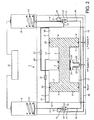
- a double-acting hydraulic intensifier 1 comprises first and second cylinders 2 and 2' joined by a narrower cylinder section 3.
- Reciprocally slidable in cylinder 2 is a piston 4 and reciprocally slidable in cylinder 2' is a piston 4', pistons 4 and 4' being joined by a cylindrical member 5 extending through and slidable in cylinder section 3.
- member 5 piston 4 has a first face 6, on the left-hand side in the figure, which has a greater surface area than its second, opposite face 7
- piston 4' has a first face 6', on the righthand side in the figure, which has a greater surface area than its second, opposite face 7'.
- a solenoid operated pilot valve On each side of the intensifier there is a solenoid operated pilot valve. More particularly, on each side there is: a solenoid 8 or 8' which operates a push rod 9 or 9'; and a hydraulic pilot valve 10 or 10' that has two ports 11 and 12 or 11' and 12' that can be closed by a small ball bearing 13 or 13' that is loose between them.
- the solenoid when the solenoid is de-energised, the rod 9 or 9' presses down on the ball bearing 13 or 13' by the action of a spring 14 or 14' of the solenoid to close the port 11 or 11' but allow trapped hydraulic fluid to vent to a return via port 12 or 12' and a passageway 15 or 15'.
- the solenoid 8 or 8' When the solenoid 8 or 8' is energised, the rod 9 or 9' is moved upwards against the action of spring 14 or 14' to allow ball bearing 13 or 13' to cover the return port 12 or 12'.
- a supply of low pressure (LP) hydraulic fluid is in communication with valves 10 and 10' via passageways 16 and 16' respectively.
- valves 10 and 10' On the side of pistons 4 and 4' with smaller area faces (the high pressure sides), there are chambers 17 and 17' respectively, on the opposite (low pressure) sides there being chambers 18 and 18'.
- the valves 10 and 10' are linked with chambers 18 and 18' via input passageway 19 and 19' respectively.
- Chamber 18 is in communication with chamber 17' via a passageway 20 through member 3 and a non-return valve 21; and chamber 18' is in communication with chamber 17 via a passageway 20' through member 3 and a non-return valve 21'. Chambers 17 and 17' are in communication with a high pressure (HP) supply output via non-return valves 22 and 22' respectively.
- HP high pressure
- Reference numerals 23 and 23' denote seals via which pistons 4 and 4' slide in cylinders 2 and 2' respectively and reference numerals 24 denote seals against which member 5 slides in section 3.
- Reference numeral 25 denotes electronic operating means for alternately energising and de-energising the solenoids 8 and 8', one after the other.
- the electronic means 25 could be provided by a multivibrator module attached to or located close to the intensifier for other than subsea well usage.
- the function of electronic means 25 could be provided by a subsea electronics module (SEM) of the well control system.
- SEM subsea electronics module
- Fig. 2 shows an alternative form of intensifier to that of Fig. 1 in that, for the sake of ease of manufacture, passageway 20 and valve 21 and passageway 20' and valve 21' are external of pistons 4 and 4' and cylinder member 3. Otherwise, its arrangement and manner of operation are identical to the intensifier of Fig. 1 .
- the pressure intensifier of this invention is more reliable, cheaper to manufacture and does not have the fluid leakage problems of current designs.
Claims (4)
- Hydraulikverstärker (1), umfassend:einen ersten Kolben (4), der in einem ersten Zylinder (2) hin und her bewegbar ist;einen zweiten Kolben (4'), der in einem zweiten Zylinder (2') hin und her bewegbar ist;ein zylindrisches Element (5), das die Kolben so verbindet, dass sie bedingt durch das zylindrische Element jeweils eine erste Seite (6 bzw. 6') aufweisen, die eine größere Fläche hat als ihre zweite, gegenüberliegende Seite (7 bzw. 7'), wobei sich die erste Seite jedes der Kolben an einer jeweiligen Niederdruckseite befindet und sich die zweite Seite jedes der Kolben an einer jeweiligen Hochdruckseite befindet,erste und zweite Eingänge (19, 19') für die Zufuhr von Niederdruck-Hydraulikfluid zu jeweiligen der Niederdruckseiten;einen Ausgang für Hochdruck-Hydraulikfluid von den Hochdruckseiten;erste und zweite magnetisch betätigte Steuerventile (8, 8') zur Steuerung der Zufuhr von Niederdruck-Hydraulikfluid zu jeweiligen der Eingänge;elektronische Mittel (25), die für die Betätigung der Steuerventile zwecks der abwechselnden Zufuhr von Niederdruck-Hydraulikfluid zu den Eingängen eingerichtet sind; undKopplungsmittel (20, 20', 21, 21') zwischen dem ersten und zweiten Kolben, dadurch gekennzeichnet, dass:das Kopplungsmittel derart ist, dass beim Anliegen von Niederdruckfluid an einer der Niederdruckseiten das Niederdruckfluid auch von der Niederdruckseite durch das Kopplungsmittel zur Hochdruckseite des anderen der Kolben fließt, wobei das Kopplungsmittel einen ersten Durchlass (20) zwischen der Niederdruckseite des ersten Kolbens und der Hochdruckseite des zweiten Kolbens und einen zweiten Durchlass (20') zwischen der Niederdruckseite des zweiten Kolbens und der Hochdruckseite des ersten Kolbens umfasst, wobei die Durchlässe jeweils mit einem entsprechenden Rückschlagventil (21 bzw. 21') versehen sind, um Durchfluss von der Niederdruckseite zur Hochdruckseite zu ermöglichen.
- Verstärker (1) nach Anspruch 1, wobei das elektronische Mittel (25) durch ein unterseeisches Elektronikmodul eines Steuersystems eines unterseeischen Bohrlochs bereitgestellt wird.
- Verfahren zur Erzeugung von Hochdruck-Hydraulikfluid, umfassend die Bereitstellung eines Hydraulikverstärkers (1), umfassend:einen ersten Kolben (4), der in einem ersten Zylinder (2) hin und her bewegbar ist;einen zweiten Kolben (4'), der in einem zweiten Zylinder (2') hin und her bewegbar ist;ein zylindrisches Element (5), das die Kolben so verbindet, dass sie bedingt durch das zylindrische Element jeweils eine erste Seite (6 bzw. 6') aufweisen, die eine größere Fläche hat als ihre zweite, gegenüberliegende Seite (7 bzw. 7'), wobei sich die erste Seite jedes der Kolben an einer jeweiligen Niederdruckseite befindet und sich die zweite Seite jedes der Kolben an einer jeweiligen Hochdruckseite befindet,erste und zweite Eingänge (19, 19') für die Zufuhr von Niederdruck-Hydraulikfluid zu jeweiligen der Niederdruckseiten; undeinen Ausgang für Hochdruck-Hydraulikfluid von den Hochdruckseiten;wobei erste und zweite magnetisch betätigte Steuerventile (8, 8') vorgesehen sind, welche die Zufuhr des Niederdruck-Hydraulikfluids zu jeweiligen der Eingänge steuern;elektronische Mittel (25), welche die Steuerventile betätigen, um den Eingängen abwechselnd Niederdruck-Hydraulikfluid zuzuführen; undKopplungsmittel zwischen dem ersten und zweiten Kolben, dadurch gekennzeichnet, dass:beim Anliegen von Niederdruckfluid an einer der Niederdruckseiten das Kopplungsmittel (20, 20', 21, 21') derart ist, dass das Niederdruckfluid auch von der Niederdruckseite durch das Kopplungsmittel zur Hochdruckseite des anderen der Kolben fließt, wobei das Kopplungsmittel einen ersten Durchlass (20) zwischen der Niederdruckseite des ersten Kolbens und der Hochdruckseite des zweiten Kolbens und einen zweiten Durchlass (20') zwischen der Niederdruckseite des zweiten Kolbens und der Hochdruckseite des ersten Kolbens umfasst, wobei die Durchlässe jeweils mit einem entsprechenden Rückschlagventil (21 bzw. 21') versehen sind, um Durchfluss von der Niederdruckseite zur Hochdruckseite zu ermöglichen.
- Verfahren nach Anspruch 3, wobei das elektronische Mittel (25) durch ein unterseeisches Elektronikmodul eines Steuersystems eines unterseeischen Bohrlochs bereitgestellt wird.
Priority Applications (7)
| Application Number | Priority Date | Filing Date | Title |
|---|---|---|---|
| EP10189641.3A EP2447545B1 (de) | 2010-11-02 | 2010-11-02 | Hochdruckverstärker |
| MYPI2013001282A MY163844A (en) | 2010-11-02 | 2011-10-31 | High pressure intensifiers |
| PCT/EP2011/069172 WO2012059478A1 (en) | 2010-11-02 | 2011-10-31 | High pressure intensifiers |
| AU2011325186A AU2011325186B2 (en) | 2010-11-02 | 2011-10-31 | High pressure intensifiers |
| US13/883,210 US9938993B2 (en) | 2010-11-02 | 2011-10-31 | High pressure intensifiers |
| SG2013032495A SG190045A1 (en) | 2010-11-02 | 2011-10-31 | High pressure intensifiers |
| CN201180052978.7A CN103201521B (zh) | 2010-11-02 | 2011-10-31 | 高压增强器 |
Applications Claiming Priority (1)
| Application Number | Priority Date | Filing Date | Title |
|---|---|---|---|
| EP10189641.3A EP2447545B1 (de) | 2010-11-02 | 2010-11-02 | Hochdruckverstärker |
Publications (2)
| Publication Number | Publication Date |
|---|---|
| EP2447545A1 EP2447545A1 (de) | 2012-05-02 |
| EP2447545B1 true EP2447545B1 (de) | 2015-01-07 |
Family
ID=43778461
Family Applications (1)
| Application Number | Title | Priority Date | Filing Date |
|---|---|---|---|
| EP10189641.3A Active EP2447545B1 (de) | 2010-11-02 | 2010-11-02 | Hochdruckverstärker |
Country Status (7)
| Country | Link |
|---|---|
| US (1) | US9938993B2 (de) |
| EP (1) | EP2447545B1 (de) |
| CN (1) | CN103201521B (de) |
| AU (1) | AU2011325186B2 (de) |
| MY (1) | MY163844A (de) |
| SG (1) | SG190045A1 (de) |
| WO (1) | WO2012059478A1 (de) |
Families Citing this family (6)
| Publication number | Priority date | Publication date | Assignee | Title |
|---|---|---|---|---|
| US9429146B2 (en) * | 2012-04-25 | 2016-08-30 | John J. Fong | Pressure intensifier |
| CN106015129A (zh) * | 2016-06-27 | 2016-10-12 | 晋中浩普液压设备有限公司 | 一种单多控转换往复增压器 |
| CN106425892A (zh) * | 2016-12-08 | 2017-02-22 | 中国矿业大学 | 一种新型的浆体磨料射流系统 |
| JP6673554B2 (ja) | 2017-04-28 | 2020-03-25 | Smc株式会社 | 増圧装置及びそれを備えたシリンダ装置 |
| FR3090761B1 (fr) * | 2018-12-19 | 2021-11-26 | Poclain Hydraulics Ind | Convertisseur de pression hydraulique, procédé de conversion de pression hydraulique et véhicule équipé |
| ES2905685T3 (es) | 2019-04-11 | 2022-04-11 | Piston Power S R O | Disposición de amplificador de presión hidráulica |
Family Cites Families (13)
| Publication number | Priority date | Publication date | Assignee | Title |
|---|---|---|---|---|
| US2508298A (en) * | 1948-04-16 | 1950-05-16 | Oliver J Saari | Fluid pressure intensifying device |
| FR1414350A (fr) * | 1964-11-14 | 1965-10-15 | Appareil multiplicateur de pression fluide | |
| IT976905B (it) | 1973-01-16 | 1974-09-10 | Consiglio Nazionale Ricerche | Apparato per fornire una pressione variaile nel tempo con elegge prestabilita |
| DE3640236A1 (de) | 1986-11-25 | 1988-06-01 | Rexroth Mannesmann Gmbh | Anordnung zum erzeugen hoher hydraulischer druecke |
| GB2275969B (en) | 1993-03-01 | 1997-09-17 | Europ Gas Turbines Ltd | Hydraulic intensifier |
| JP3019671B2 (ja) | 1993-05-27 | 2000-03-13 | ダイキン工業株式会社 | 超高圧制御装置 |
| US6651749B1 (en) | 2000-03-30 | 2003-11-25 | Halliburton Energy Services, Inc. | Well tool actuators and method |
| CA2431620A1 (en) * | 2003-06-10 | 2004-12-10 | Daniel L. Forest | Membrane and hydraulic intensifier purification system |
| JP4301310B2 (ja) * | 2007-03-12 | 2009-07-22 | Smc株式会社 | 増圧装置 |
| GB2461061A (en) * | 2008-06-19 | 2009-12-23 | Vetco Gray Controls Ltd | Subsea hydraulic intensifier with supply directional control valves electronically switched |
| CN201339616Y (zh) * | 2008-12-22 | 2009-11-04 | 陈涛 | 一种液压驱动增压装置 |
| CN201547038U (zh) * | 2009-09-30 | 2010-08-11 | 山东交通学院 | 液压增压器 |
| CN201621112U (zh) * | 2010-04-09 | 2010-11-03 | 江西洪都航空工业集团有限责任公司 | 油-气压力转换增压装置 |
-
2010
- 2010-11-02 EP EP10189641.3A patent/EP2447545B1/de active Active
-
2011
- 2011-10-31 US US13/883,210 patent/US9938993B2/en active Active
- 2011-10-31 AU AU2011325186A patent/AU2011325186B2/en active Active
- 2011-10-31 CN CN201180052978.7A patent/CN103201521B/zh not_active Expired - Fee Related
- 2011-10-31 MY MYPI2013001282A patent/MY163844A/en unknown
- 2011-10-31 WO PCT/EP2011/069172 patent/WO2012059478A1/en active Application Filing
- 2011-10-31 SG SG2013032495A patent/SG190045A1/en unknown
Also Published As
| Publication number | Publication date |
|---|---|
| CN103201521A (zh) | 2013-07-10 |
| AU2011325186B2 (en) | 2016-04-21 |
| MY163844A (en) | 2017-10-31 |
| WO2012059478A1 (en) | 2012-05-10 |
| US20140072454A1 (en) | 2014-03-13 |
| CN103201521B (zh) | 2016-02-10 |
| EP2447545A1 (de) | 2012-05-02 |
| AU2011325186A1 (en) | 2013-05-23 |
| SG190045A1 (en) | 2013-06-28 |
| US9938993B2 (en) | 2018-04-10 |
Similar Documents
| Publication | Publication Date | Title |
|---|---|---|
| EP2447545B1 (de) | Hochdruckverstärker | |
| US8215408B2 (en) | Actuation system for well tools | |
| EP2136085A2 (de) | Hydraulische Druckübersetzer | |
| GB2464907A (en) | Downhole hydraulic valve systems | |
| EP1927759A1 (de) | Doppelrückschlagventil mit Schwimmfunktion | |
| CN103697010A (zh) | 集成液压阀组及液压驱动系统及混凝土泵 | |
| US20060005697A1 (en) | Fluid power unit having closed circuit | |
| US20150013804A1 (en) | Flow responsive latch for holding a spool valve in an open position | |
| US9222594B2 (en) | Directional valve equipped with pressure control | |
| KR102094425B1 (ko) | 개방 단부 위치에서 감소된 흐름을 위한 스풀 상의 계측 노치를 갖는 방향 제어 밸브 | |
| KR101769644B1 (ko) | 다중 유체펌프 결합회로 | |
| CN106015129A (zh) | 一种单多控转换往复增压器 | |
| US20180347599A1 (en) | Valve device | |
| CN103557199A (zh) | 一种变截面液压缸及其液压控制系统和控制方法 | |
| JP2004205043A (ja) | 低エネルギ消費のソレノイド弁 | |
| JP2020518454A (ja) | 伝動効率が高い自由鍛造油圧機及びその作動方法 | |
| US20200277839A1 (en) | System and methodology for controlling actuation of devices downhole | |
| US6276396B1 (en) | Directional control valves | |
| CN107208399B (zh) | 用于建筑设备的控制阀 | |
| KR100936143B1 (ko) | 공기압축 기능을 갖는 유압펌프 | |
| US7713033B2 (en) | Double-acting, duplex pump controlled by two, two position spool valves | |
| CN103557208A (zh) | 多级可调式液压油缸 | |
| US20200362885A1 (en) | Pilot Close Vent Valve | |
| KR101366438B1 (ko) | 복동식 왕복가능 유체 기구용 제어밸브 | |
| US9897115B2 (en) | Hydraulic system |
Legal Events
| Date | Code | Title | Description |
|---|---|---|---|
| PUAI | Public reference made under article 153(3) epc to a published international application that has entered the european phase |
Free format text: ORIGINAL CODE: 0009012 |
|
| AK | Designated contracting states |
Kind code of ref document: A1 Designated state(s): AL AT BE BG CH CY CZ DE DK EE ES FI FR GB GR HR HU IE IS IT LI LT LU LV MC MK MT NL NO PL PT RO RS SE SI SK SM TR |
|
| AX | Request for extension of the european patent |
Extension state: BA ME |
|
| 17P | Request for examination filed |
Effective date: 20130109 |
|
| 17Q | First examination report despatched |
Effective date: 20130304 |
|
| GRAP | Despatch of communication of intention to grant a patent |
Free format text: ORIGINAL CODE: EPIDOSNIGR1 |
|
| INTG | Intention to grant announced |
Effective date: 20140618 |
|
| GRAS | Grant fee paid |
Free format text: ORIGINAL CODE: EPIDOSNIGR3 |
|
| GRAA | (expected) grant |
Free format text: ORIGINAL CODE: 0009210 |
|
| AK | Designated contracting states |
Kind code of ref document: B1 Designated state(s): AL AT BE BG CH CY CZ DE DK EE ES FI FR GB GR HR HU IE IS IT LI LT LU LV MC MK MT NL NO PL PT RO RS SE SI SK SM TR |
|
| REG | Reference to a national code |
Ref country code: GB Ref legal event code: FG4D |
|
| REG | Reference to a national code |
Ref country code: CH Ref legal event code: EP |
|
| REG | Reference to a national code |
Ref country code: IE Ref legal event code: FG4D |
|
| REG | Reference to a national code |
Ref country code: AT Ref legal event code: REF Ref document number: 705930 Country of ref document: AT Kind code of ref document: T Effective date: 20150215 |
|
| REG | Reference to a national code |
Ref country code: DE Ref legal event code: R096 Ref document number: 602010021557 Country of ref document: DE Effective date: 20150226 |
|
| REG | Reference to a national code |
Ref country code: NL Ref legal event code: VDEP Effective date: 20150107 |
|
| REG | Reference to a national code |
Ref country code: NO Ref legal event code: T2 Effective date: 20150107 Ref country code: AT Ref legal event code: MK05 Ref document number: 705930 Country of ref document: AT Kind code of ref document: T Effective date: 20150107 |
|
| RAP2 | Party data changed (patent owner data changed or rights of a patent transferred) |
Owner name: GE OIL & GAS UK LIMITED |
|
| REG | Reference to a national code |
Ref country code: LT Ref legal event code: MG4D |
|
| REG | Reference to a national code |
Ref country code: GB Ref legal event code: 732E Free format text: REGISTERED BETWEEN 20150625 AND 20150701 |
|
| PG25 | Lapsed in a contracting state [announced via postgrant information from national office to epo] |
Ref country code: BG Free format text: LAPSE BECAUSE OF FAILURE TO SUBMIT A TRANSLATION OF THE DESCRIPTION OR TO PAY THE FEE WITHIN THE PRESCRIBED TIME-LIMIT Effective date: 20150407 Ref country code: LT Free format text: LAPSE BECAUSE OF FAILURE TO SUBMIT A TRANSLATION OF THE DESCRIPTION OR TO PAY THE FEE WITHIN THE PRESCRIBED TIME-LIMIT Effective date: 20150107 Ref country code: FI Free format text: LAPSE BECAUSE OF FAILURE TO SUBMIT A TRANSLATION OF THE DESCRIPTION OR TO PAY THE FEE WITHIN THE PRESCRIBED TIME-LIMIT Effective date: 20150107 Ref country code: ES Free format text: LAPSE BECAUSE OF FAILURE TO SUBMIT A TRANSLATION OF THE DESCRIPTION OR TO PAY THE FEE WITHIN THE PRESCRIBED TIME-LIMIT Effective date: 20150107 Ref country code: SE Free format text: LAPSE BECAUSE OF FAILURE TO SUBMIT A TRANSLATION OF THE DESCRIPTION OR TO PAY THE FEE WITHIN THE PRESCRIBED TIME-LIMIT Effective date: 20150107 Ref country code: HR Free format text: LAPSE BECAUSE OF FAILURE TO SUBMIT A TRANSLATION OF THE DESCRIPTION OR TO PAY THE FEE WITHIN THE PRESCRIBED TIME-LIMIT Effective date: 20150107 |
|
| PG25 | Lapsed in a contracting state [announced via postgrant information from national office to epo] |
Ref country code: LV Free format text: LAPSE BECAUSE OF FAILURE TO SUBMIT A TRANSLATION OF THE DESCRIPTION OR TO PAY THE FEE WITHIN THE PRESCRIBED TIME-LIMIT Effective date: 20150107 Ref country code: PL Free format text: LAPSE BECAUSE OF FAILURE TO SUBMIT A TRANSLATION OF THE DESCRIPTION OR TO PAY THE FEE WITHIN THE PRESCRIBED TIME-LIMIT Effective date: 20150107 Ref country code: RS Free format text: LAPSE BECAUSE OF FAILURE TO SUBMIT A TRANSLATION OF THE DESCRIPTION OR TO PAY THE FEE WITHIN THE PRESCRIBED TIME-LIMIT Effective date: 20150107 Ref country code: AT Free format text: LAPSE BECAUSE OF FAILURE TO SUBMIT A TRANSLATION OF THE DESCRIPTION OR TO PAY THE FEE WITHIN THE PRESCRIBED TIME-LIMIT Effective date: 20150107 Ref country code: NL Free format text: LAPSE BECAUSE OF FAILURE TO SUBMIT A TRANSLATION OF THE DESCRIPTION OR TO PAY THE FEE WITHIN THE PRESCRIBED TIME-LIMIT Effective date: 20150107 Ref country code: GR Free format text: LAPSE BECAUSE OF FAILURE TO SUBMIT A TRANSLATION OF THE DESCRIPTION OR TO PAY THE FEE WITHIN THE PRESCRIBED TIME-LIMIT Effective date: 20150408 Ref country code: IS Free format text: LAPSE BECAUSE OF FAILURE TO SUBMIT A TRANSLATION OF THE DESCRIPTION OR TO PAY THE FEE WITHIN THE PRESCRIBED TIME-LIMIT Effective date: 20150507 |
|
| REG | Reference to a national code |
Ref country code: DE Ref legal event code: R097 Ref document number: 602010021557 Country of ref document: DE |
|
| REG | Reference to a national code |
Ref country code: DE Ref legal event code: R082 Ref document number: 602010021557 Country of ref document: DE Representative=s name: RUEGER | ABEL PATENT- UND RECHTSANWAELTE, DE Ref country code: DE Ref legal event code: R082 Ref document number: 602010021557 Country of ref document: DE Representative=s name: RUEGER, BARTHELT & ABEL PATENTANWAELTE, DE Ref country code: DE Ref legal event code: R082 Ref document number: 602010021557 Country of ref document: DE Representative=s name: RUEGER ABEL PATENT- UND RECHTSANWAELTE, DE |
|
| PG25 | Lapsed in a contracting state [announced via postgrant information from national office to epo] |
Ref country code: CZ Free format text: LAPSE BECAUSE OF FAILURE TO SUBMIT A TRANSLATION OF THE DESCRIPTION OR TO PAY THE FEE WITHIN THE PRESCRIBED TIME-LIMIT Effective date: 20150107 Ref country code: RO Free format text: LAPSE BECAUSE OF FAILURE TO SUBMIT A TRANSLATION OF THE DESCRIPTION OR TO PAY THE FEE WITHIN THE PRESCRIBED TIME-LIMIT Effective date: 20150107 Ref country code: SK Free format text: LAPSE BECAUSE OF FAILURE TO SUBMIT A TRANSLATION OF THE DESCRIPTION OR TO PAY THE FEE WITHIN THE PRESCRIBED TIME-LIMIT Effective date: 20150107 Ref country code: EE Free format text: LAPSE BECAUSE OF FAILURE TO SUBMIT A TRANSLATION OF THE DESCRIPTION OR TO PAY THE FEE WITHIN THE PRESCRIBED TIME-LIMIT Effective date: 20150107 Ref country code: DK Free format text: LAPSE BECAUSE OF FAILURE TO SUBMIT A TRANSLATION OF THE DESCRIPTION OR TO PAY THE FEE WITHIN THE PRESCRIBED TIME-LIMIT Effective date: 20150107 |
|
| REG | Reference to a national code |
Ref country code: DE Ref legal event code: R082 Ref document number: 602010021557 Country of ref document: DE Representative=s name: RUEGER | ABEL PATENT- UND RECHTSANWAELTE, DE Ref country code: DE Ref legal event code: R082 Ref document number: 602010021557 Country of ref document: DE Representative=s name: RUEGER, BARTHELT & ABEL PATENTANWAELTE, DE Ref country code: DE Ref legal event code: R081 Ref document number: 602010021557 Country of ref document: DE Owner name: GE OIL & GAS UK LTD., NAILSEA, GB Free format text: FORMER OWNER: VETCO GRAY CONTROLS LIMITED, BRISTOL, NAILSEA, GB Ref country code: DE Ref legal event code: R082 Ref document number: 602010021557 Country of ref document: DE Representative=s name: RUEGER ABEL PATENT- UND RECHTSANWAELTE, DE |
|
| PLBE | No opposition filed within time limit |
Free format text: ORIGINAL CODE: 0009261 |
|
| STAA | Information on the status of an ep patent application or granted ep patent |
Free format text: STATUS: NO OPPOSITION FILED WITHIN TIME LIMIT |
|
| REG | Reference to a national code |
Ref country code: FR Ref legal event code: PLFP Year of fee payment: 6 |
|
| 26N | No opposition filed |
Effective date: 20151008 |
|
| REG | Reference to a national code |
Ref country code: FR Ref legal event code: TP Owner name: GE OIL & GAS UK LIMITED, GB Effective date: 20151116 |
|
| PG25 | Lapsed in a contracting state [announced via postgrant information from national office to epo] |
Ref country code: IT Free format text: LAPSE BECAUSE OF FAILURE TO SUBMIT A TRANSLATION OF THE DESCRIPTION OR TO PAY THE FEE WITHIN THE PRESCRIBED TIME-LIMIT Effective date: 20150107 |
|
| PG25 | Lapsed in a contracting state [announced via postgrant information from national office to epo] |
Ref country code: SI Free format text: LAPSE BECAUSE OF FAILURE TO SUBMIT A TRANSLATION OF THE DESCRIPTION OR TO PAY THE FEE WITHIN THE PRESCRIBED TIME-LIMIT Effective date: 20150107 |
|
| PG25 | Lapsed in a contracting state [announced via postgrant information from national office to epo] |
Ref country code: BE Free format text: LAPSE BECAUSE OF FAILURE TO SUBMIT A TRANSLATION OF THE DESCRIPTION OR TO PAY THE FEE WITHIN THE PRESCRIBED TIME-LIMIT Effective date: 20150107 |
|
| PG25 | Lapsed in a contracting state [announced via postgrant information from national office to epo] |
Ref country code: LU Free format text: LAPSE BECAUSE OF FAILURE TO SUBMIT A TRANSLATION OF THE DESCRIPTION OR TO PAY THE FEE WITHIN THE PRESCRIBED TIME-LIMIT Effective date: 20151102 Ref country code: MC Free format text: LAPSE BECAUSE OF FAILURE TO SUBMIT A TRANSLATION OF THE DESCRIPTION OR TO PAY THE FEE WITHIN THE PRESCRIBED TIME-LIMIT Effective date: 20150107 |
|
| REG | Reference to a national code |
Ref country code: CH Ref legal event code: PL |
|
| PG25 | Lapsed in a contracting state [announced via postgrant information from national office to epo] |
Ref country code: LI Free format text: LAPSE BECAUSE OF NON-PAYMENT OF DUE FEES Effective date: 20151130 Ref country code: CH Free format text: LAPSE BECAUSE OF NON-PAYMENT OF DUE FEES Effective date: 20151130 |
|
| REG | Reference to a national code |
Ref country code: IE Ref legal event code: MM4A |
|
| PG25 | Lapsed in a contracting state [announced via postgrant information from national office to epo] |
Ref country code: IE Free format text: LAPSE BECAUSE OF NON-PAYMENT OF DUE FEES Effective date: 20151102 |
|
| REG | Reference to a national code |
Ref country code: FR Ref legal event code: PLFP Year of fee payment: 7 |
|
| PG25 | Lapsed in a contracting state [announced via postgrant information from national office to epo] |
Ref country code: SM Free format text: LAPSE BECAUSE OF FAILURE TO SUBMIT A TRANSLATION OF THE DESCRIPTION OR TO PAY THE FEE WITHIN THE PRESCRIBED TIME-LIMIT Effective date: 20150107 Ref country code: HU Free format text: LAPSE BECAUSE OF FAILURE TO SUBMIT A TRANSLATION OF THE DESCRIPTION OR TO PAY THE FEE WITHIN THE PRESCRIBED TIME-LIMIT; INVALID AB INITIO Effective date: 20101102 |
|
| PG25 | Lapsed in a contracting state [announced via postgrant information from national office to epo] |
Ref country code: CY Free format text: LAPSE BECAUSE OF FAILURE TO SUBMIT A TRANSLATION OF THE DESCRIPTION OR TO PAY THE FEE WITHIN THE PRESCRIBED TIME-LIMIT Effective date: 20150107 |
|
| PG25 | Lapsed in a contracting state [announced via postgrant information from national office to epo] |
Ref country code: MT Free format text: LAPSE BECAUSE OF FAILURE TO SUBMIT A TRANSLATION OF THE DESCRIPTION OR TO PAY THE FEE WITHIN THE PRESCRIBED TIME-LIMIT Effective date: 20150107 Ref country code: TR Free format text: LAPSE BECAUSE OF FAILURE TO SUBMIT A TRANSLATION OF THE DESCRIPTION OR TO PAY THE FEE WITHIN THE PRESCRIBED TIME-LIMIT Effective date: 20150107 |
|
| REG | Reference to a national code |
Ref country code: FR Ref legal event code: PLFP Year of fee payment: 8 |
|
| PG25 | Lapsed in a contracting state [announced via postgrant information from national office to epo] |
Ref country code: MK Free format text: LAPSE BECAUSE OF FAILURE TO SUBMIT A TRANSLATION OF THE DESCRIPTION OR TO PAY THE FEE WITHIN THE PRESCRIBED TIME-LIMIT Effective date: 20150107 Ref country code: PT Free format text: LAPSE BECAUSE OF FAILURE TO SUBMIT A TRANSLATION OF THE DESCRIPTION OR TO PAY THE FEE WITHIN THE PRESCRIBED TIME-LIMIT Effective date: 20150107 |
|
| REG | Reference to a national code |
Ref country code: FR Ref legal event code: PLFP Year of fee payment: 9 |
|
| PG25 | Lapsed in a contracting state [announced via postgrant information from national office to epo] |
Ref country code: AL Free format text: LAPSE BECAUSE OF FAILURE TO SUBMIT A TRANSLATION OF THE DESCRIPTION OR TO PAY THE FEE WITHIN THE PRESCRIBED TIME-LIMIT Effective date: 20150107 |
|
| PGFP | Annual fee paid to national office [announced via postgrant information from national office to epo] |
Ref country code: GB Payment date: 20231019 Year of fee payment: 14 |
|
| PGFP | Annual fee paid to national office [announced via postgrant information from national office to epo] |
Ref country code: NO Payment date: 20231023 Year of fee payment: 14 Ref country code: FR Payment date: 20231019 Year of fee payment: 14 Ref country code: DE Payment date: 20231019 Year of fee payment: 14 |