EP2446978A1 - Method and device for producing hardened moulded components - Google Patents
Method and device for producing hardened moulded components Download PDFInfo
- Publication number
- EP2446978A1 EP2446978A1 EP12151528A EP12151528A EP2446978A1 EP 2446978 A1 EP2446978 A1 EP 2446978A1 EP 12151528 A EP12151528 A EP 12151528A EP 12151528 A EP12151528 A EP 12151528A EP 2446978 A1 EP2446978 A1 EP 2446978A1
- Authority
- EP
- European Patent Office
- Prior art keywords
- coolant
- tool
- pressure
- mold
- thermoforming
- Prior art date
- Legal status (The legal status is an assumption and is not a legal conclusion. Google has not performed a legal analysis and makes no representation as to the accuracy of the status listed.)
- Granted
Links
Images


Classifications
-
- B—PERFORMING OPERATIONS; TRANSPORTING
- B21—MECHANICAL METAL-WORKING WITHOUT ESSENTIALLY REMOVING MATERIAL; PUNCHING METAL
- B21D—WORKING OR PROCESSING OF SHEET METAL OR METAL TUBES, RODS OR PROFILES WITHOUT ESSENTIALLY REMOVING MATERIAL; PUNCHING METAL
- B21D22/00—Shaping without cutting, by stamping, spinning, or deep-drawing
- B21D22/02—Stamping using rigid devices or tools
- B21D22/022—Stamping using rigid devices or tools by heating the blank or stamping associated with heat treatment
-
- B—PERFORMING OPERATIONS; TRANSPORTING
- B21—MECHANICAL METAL-WORKING WITHOUT ESSENTIALLY REMOVING MATERIAL; PUNCHING METAL
- B21D—WORKING OR PROCESSING OF SHEET METAL OR METAL TUBES, RODS OR PROFILES WITHOUT ESSENTIALLY REMOVING MATERIAL; PUNCHING METAL
- B21D22/00—Shaping without cutting, by stamping, spinning, or deep-drawing
- B21D22/20—Deep-drawing
- B21D22/208—Deep-drawing by heating the blank or deep-drawing associated with heat treatment
-
- B—PERFORMING OPERATIONS; TRANSPORTING
- B21—MECHANICAL METAL-WORKING WITHOUT ESSENTIALLY REMOVING MATERIAL; PUNCHING METAL
- B21D—WORKING OR PROCESSING OF SHEET METAL OR METAL TUBES, RODS OR PROFILES WITHOUT ESSENTIALLY REMOVING MATERIAL; PUNCHING METAL
- B21D37/00—Tools as parts of machines covered by this subclass
- B21D37/16—Heating or cooling
-
- C—CHEMISTRY; METALLURGY
- C21—METALLURGY OF IRON
- C21D—MODIFYING THE PHYSICAL STRUCTURE OF FERROUS METALS; GENERAL DEVICES FOR HEAT TREATMENT OF FERROUS OR NON-FERROUS METALS OR ALLOYS; MAKING METAL MALLEABLE, e.g. BY DECARBURISATION OR TEMPERING
- C21D1/00—General methods or devices for heat treatment, e.g. annealing, hardening, quenching or tempering
- C21D1/02—Hardening articles or materials formed by forging or rolling, with no further heating beyond that required for the formation
-
- C—CHEMISTRY; METALLURGY
- C21—METALLURGY OF IRON
- C21D—MODIFYING THE PHYSICAL STRUCTURE OF FERROUS METALS; GENERAL DEVICES FOR HEAT TREATMENT OF FERROUS OR NON-FERROUS METALS OR ALLOYS; MAKING METAL MALLEABLE, e.g. BY DECARBURISATION OR TEMPERING
- C21D1/00—General methods or devices for heat treatment, e.g. annealing, hardening, quenching or tempering
- C21D1/62—Quenching devices
- C21D1/673—Quenching devices for die quenching
-
- C—CHEMISTRY; METALLURGY
- C22—METALLURGY; FERROUS OR NON-FERROUS ALLOYS; TREATMENT OF ALLOYS OR NON-FERROUS METALS
- C22C—ALLOYS
- C22C38/00—Ferrous alloys, e.g. steel alloys
- C22C38/02—Ferrous alloys, e.g. steel alloys containing silicon
-
- C—CHEMISTRY; METALLURGY
- C22—METALLURGY; FERROUS OR NON-FERROUS ALLOYS; TREATMENT OF ALLOYS OR NON-FERROUS METALS
- C22C—ALLOYS
- C22C38/00—Ferrous alloys, e.g. steel alloys
- C22C38/04—Ferrous alloys, e.g. steel alloys containing manganese
Definitions
- the invention relates to a method and an apparatus for producing hardened molded components, in particular of structural or body parts of motor vehicles.
- high-strength steel sheets are used in the automotive industry, which are hot-formed to form components and press-hardened.
- the hot working and press hardening of metal sheets as such is known, for example, by the DE 24 524 86 A1 , Here, a metal plate is heated to a temperature in the specific Austenitmaschinestemperatur Kunststoff the erkstoffs, that is, to a temperature above the transition temperature AC1, preferably greater than AC3, in a heat treatment plant, then placed in a press tool and reshaped. Clamped in the press tool, the molded components are hardened by cooling.
- the cooling required for curing is divided into indirect cooling and direct cooling.
- the indirect cooling takes place via cooling channels, which are introduced in the form of holes or slots (shaft cooling) at a defined distance from the forming surface in the tool. Through these channels flows a coolant, usually water, which dissipates the heat given off by the warm mold component to the tool to the outside.
- a coolant usually water
- thermoforming tool In direct cooling, the mold component in the thermoforming mold is brought into direct contact with the cooling medium.
- thermoforming tool In the from the DE 10 2005 028 010 B3 known thermoforming tool is the lower tool of the press within a liquid bath. Both parts of the mold geometry and the entire mold geometry can be below the liquid level.
- the sheet metal profile to be molded and hardened is placed above the liquid level and immersed in the liquid bath when the press is moved by the upper tool and deep-drawn into the lower tool.
- a direct cooling in a thermoforming tool is still from the DE 26 03 618 A1 known.
- concentric annular grooves are introduced, lead into the guided through the tools channels. Through these channels, a cooling liquid is fed into the annular grooves for direct contact with a sheet metal profile to be hardened.
- This direct cooling can be at least theoretically expect improved cooling, since the cooling liquid comes into direct contact with the mold component.
- the contact pressure or the contact conditions between the molded component and the thermoforming tool have a significant influence on the heat transfer and heat dissipation.
- the tools are manufactured with CNC machines to the nearest hundredth of a millimeter and then inked to keep the gaps between the mold and the tool as small as possible.
- the coolant or liquid used is predominantly water whose high enthalpy of evaporation promotes the cooling process.
- different boiling phenomena occur on contact between the coolant and the molded component.
- the water evaporates and it forms on the mold component surface of a vapor film, which acts insulating due to the opposite to the liquid significantly lower thermal conductivity.
- the molded component therefore cools only slowly. If the surface to be cooled falls below the so-called Leidenfrost temperature, locally and irregularly distributed over the mold component surface there is direct contact between the liquid and the mold component. The dissipated heat flow increases in these areas.
- the invention is, starting from the prior art, the object of further developing a method and apparatus for producing cured mold components to increase the efficiency of heat transfer and thus improve the cooling effect and differentiated by the material characteristics of the mold components and process reliable and reproducible to be able to adjust. Furthermore, the invention aims to improve an apparatus for the production of cured molded components plant technology.
- the mold component is at least partially cooled with a coolant whose pressure is above the vapor pressure of the coolant, wherein the coolant is introduced into the mold space at a pressure of up to 25 MPa.
- Unwanted air cushions or air gaps in the thermoforming tool can be caused for example by wear on the mold or as a result of manufacturing tolerances in tool making.
- the unwanted air gap between mold component and tool or the contact surfaces in the mold cavity of the tool is closed by coolant at a pressure above the vapor pressure of the coolant in the mold space or in the tool gap between upper tool and lower tool is introduced.
- This aspect of the invention thus aims at obtaining a stable liquid phase of the refrigerant during the cooling process.
- the evaporation of the coolant is prevented by working in an elevated pressure range above the steam curve.
- the loading of the mold component with coolant in the mold space in order to cool and harden it can take place over the entire surface of the component or partially restricted to certain areas of the mold component. This gives a completely press-hardened molded component or a partially cured or partially differently hardened molded component. It is also possible different areas of the mold component to cool differently and to give these areas mutually different hardness values and strength properties.
- the coolant is introduced into the mold cavity at a pressure of up to 25 MPa, with very high volume flows. Also, the duration of the coolant supply and / or the amount of pressure can be varied. In practice, it can be assumed that the minimum pressure should be 6 MPa. It has been shown that at a pre-pressure of less than 6 MPa incomplete heat transfer leads to a significant reduction in the cooling of the workpiece and thus the strength of the finished mold member.
- the component temperature of the molded component is measured in the mold space. Furthermore, the tool temperature in the region of the contact surfaces of the mold cavity can also be measured. Depending on the component temperature and / or the tool temperature, the starting time and the end time of the coolant supply are controlled.
- the coolant distribution in the mold space is variably controllable.
- certain (first) regions of the molded component can be acted upon with coolant and other (second) regions of the molded component not.
- different areas can be acted upon by coolant from one another at different times, in order to adjust the material properties in these areas in a targeted manner or differentiated.
- the mold component is held fixed after removal from the thermoforming mold in a cooling station. As a result, a distortion of the mold component due to thermal stresses can be avoided.
- the pressure with which the coolant is introduced or injected into the mold space during the cooling phase is adjusted in terms of control technology to the vapor pressure of the coolant.
- the injection pressure it is possible to produce a water layer with good heat conduction or a wet steam with a different heat conductivity in the tool gap.
- the pressure can - as already stated above - time-controlled and / or temperature-controlled, in particular depending on a temperature measurement on the mold component in the thermoforming mold and / or on the thermoforming tool itself.
- the coolant may also be injected intermittently into the mold cavity.
- two parameters which can also be rationally implemented within the context of mass production - pulse duration and frequency - are available.
- By targeted control of the amount of coolant per pulse and their timing high heat flows can be dissipated.
- the control is particularly advantageous in such a way that one pulse per press-pressure or tool stroke is realized.
- a first solution of the objective part of the object consists in a thermoforming tool having the features of claim 5.
- the thermoforming tool comprises an upper tool and a lower tool.
- inflow channels are provided, via which a cooling medium in the formed between the upper tool and lower tool mold space and the tool gap of the closed mold space is conductive.
- the state of aggregation of the coolant is adjustable. This is done by controlling the amount of pressure with which the coolant is injected or pressed into the mold space during the cooling process.
- all the necessary control and regulating technical apparatuses and units are assigned to the thermoforming tool, in particular a high-pressure pump, a pressure booster, a High-pressure accumulator, an injection control and / or a coolant quantity control.
- the coolant can be injected with a pressure in the mold space, wherein the height of the pressure and / or the injection duration of the coolant can be controlled.
- supply lines for the coolant are provided. From the supply lines branch off injection lines, which open in the mold space. On the outlet side, the injection lines may have nozzles, preferably the injection lines open with thin openings without integrated nozzles in the mold space.
- thermoforming tool means for influencing the heat transfer are arranged in the contact surfaces of the mold space.
- Such means may in particular be heating elements, clearances, air gaps, inserts of materials with lower or higher thermal conductivity or ceramic inserts.
- This embodiment is particularly suitable for the production of partially differently cured molded components, either targeted air transfer in the air cushion with minimal heat transfer or just the greatest possible heat transfer can be realized by injecting the coolant.
- thermoforming tool provides that a measuring and evaluation unit is provided, by means of which the state of wear of the thermoforming tool or the upper tool and / or the lower tool can be determined.
- the state of wear can in particular be determined by evaluating the operating pressures, the coolant volume and / or the discharge quantities of the coolant measured at pressure relief valves.
- the wear or state determination of the thermoforming tool allows tool maintenance planning.
- thermoforming tool according to the features of claim 12.
- the thermoforming tool has an upper tool and a lower tool.
- the coolant is provided via a cooling system and introduced via inflow channels, which are provided in the upper tool and / or lower tool, in the mold space formed between the upper tool and the lower tool.
- the cooling system comprises at least one pressure generator, wherein the pressure generator is at least indirectly driven by the thermoforming tool, so the upper tool and / or the lower tool.
- the pressure generator is an energy converter in the form of a piston-cylinder unit.
- a pressure accumulator is integrated into the cooling system.
- a hydropneumatic pressure accumulator in the form of a bladder accumulator, a membrane accumulator or a piston accumulator is used.
- the hydropneumatic accumulator is a hydraulic component that utilizes the compressibility of gas, typically nitrogen, to store the pressure and volume of the incompressible coolant in the cooling system.
- the pressure accumulator consists of a high-strength steel container. The liquid and the gas part are separated by a gas-tight separating element (bubble or membrane). The fluid space of the pressure accumulator is in communication with the cooling system. As the pressure increases, coolant flows into the liquid space, compressing the gas (nitrogen) in the gas space. As the pressure drops, the compressed gas expands, thus providing the stored energy to the cooling system.
- the basic supply of the cooling system with coolant takes place via a priming pump.
- the priming pump leads coolant to the pressure generator.
- the Vorchirllpumpe and the pressure generator are connected via a line in which a check valve is integrated.
- the pressure generator fills the accumulator during the closing movement of the thermoforming tool.
- the or pressure generator is preferably mechanically coupled to the upper tool of the thermoforming tool.
- the coolant supply is opened and coolant is removed from the pressure accumulator.
- the pressure accumulator thus ensures the supply of coolant under high pressure of up to 25 MPa into the thermoforming tool.
- the pressure generation within the cooling system is thus completely or at least partially by the thermoforming tool itself.
- the movement of the upper tool and / or the lower tool is used when closing and opening to drive or to actuate the pressure generator.
- piston-cylinder unit is positioned instead of the tool-integrated design below the press or the thermoforming tool but is nevertheless actuated indirectly by the press pressure.
- a further embodiment variant is represented by the fact that a high-pressure pump which takes over the function of the pressure generator is positioned between the fore pump and the pressure accumulator.
- two or more pressure generators are provided.
- the coolant supply to the upper tool and the lower tool is preferably carried out separately, so that two partial cooling systems are provided. In this way, the upper tool and the lower tool are independently supplied with coolant, so that no high-pressure lines must be laid directly between the upper tool and the lower tool.
- the pressure generator and the pressure accumulator are connected to each other coolant-conducting, wherein in the connecting line between the pressure generator and pressure accumulator, a pressure relief valve and preferably another check valve are integrated.
- a filter device is integrated into the cooling system and the coolant circuit. Furthermore, a heat exchanger and / or a cooler can be provided in the cooling system. This is switched before or after the filter device or arranged in a filter tank.
- FIG. 1 shows a thermoforming tool 1.
- the thermoforming tool 1 essentially comprises an upper tool 2 and a lower tool 3, which are displaceable relative to each other and between which a mold space 4 is formed.
- Clamped in the mold space 4 can be seen a deformed mold component 5 made of steel.
- the mold gap formed between the upper tool 2 and the lower tool 3 in the closed mold space 4 is designated by 6.
- a board of hardenable steel has been heated to a hardening temperature above the austenitizing temperature, then transferred to the thermoforming tool 1 and formed. Clamped in the mold space 4, the mold component 5 is cooled and cured by a rapid cooling below the martensite start temperature.
- thermoforming tool 1 further includes here not shown pressure generator and / or a pressure accumulator and control and regulating devices for adjusting the coolant pressure and the coolant quantity, the duration of the coolant supply and temperature sensing elements.
- the coolant supply including the supply line 7, the injection line 8 and the associated printing apparatus and equipment belong to a first cooling system.
- the first cooling system works in the High pressure range, whereby the pressure and the aggregate state of the coolant KM are adjustable.
- cooling channels 11 In the upper tool 2 and in the lower tool 3 can also be seen cooling channels 11. These belong to a second cooling system, via which an indirect cooling of the mold component 5 takes place. Through the cooling channels 11, a coolant is passed, which receives the heat emitted by the warm mold component 5 to the thermoforming tool 1 and the upper tool 2 and the lower tool 3 and dissipates heat to the outside. As coolant, water is also preferably used here. Preferably, the coolant is guided in the second cooling system in a cooling circuit with recooling. While the coolant KM in the first cooling system is under high pressure, the coolant is present in the second cooling system with operating pressures of up to 0.6 MPa.
- thermoforming tool 12 corresponds to the basic structure with upper tool 2 and lower tool 3 the previously based FIG. 1 explained thermoforming tool 1. Accordingly, corresponding components or component component are provided with the same reference numerals. A further explanation is omitted.
- thermoforming tool 12 differs from the thermoforming tool 1 in that indirect cooling is eliminated and no separate cooling channels are provided in the upper tool 2 and in the lower tool 3, via which heat is removed from the thermoforming tool 12.
- FIGS. 5 and 6 show a thermoforming tool 12 - as well as from the FIG. 2 explained - together with a cooling system KS.
- the FIG. 5 shows the thermoforming tool 12 in the open position.
- the FIG. 6 shows the thermoforming tool 12 in the closed position with deformed and clamped mold component. 5
- thermoforming tool 12 has an upper tool 2 and a lower tool 3, which are displaceable relative to one another and between which a molding space 4 is formed.
- cooling system KS include pressure generator 13 and a pressure accumulator 14 together with control and regulating equipment and devices as well as shut-off valves and a Vorhellpumpe 15th
- the cooling system KS has two pressure generators 13 in the form of piston-cylinder units 16, 17. These are drive-coupled with the thermoforming tool 12 and are actuated by the upper tool 2.
- Each of the piston-cylinder units 16, 17 consists essentially of a cylinder 18 with a displaceable piston 19 guided therein and a piston rod 20 which is mechanically connected to the upper tool 2.
- the piston-cylinder units 16, 17 are synchronized with each other, wherein the cylinder chambers 21 communicate coolant-conducting. Due to the communication of the printing systems on all sides, a wedging of the press can be prevented, in particular in the case of a malfunction, such as, for example, a leak in one of the pressure-retaining systems.
- the Vor colllpumpe 15 supplies the cooling system KS with coolant KM and provides the necessary form.
- the coolant KM is transferred via the feed pump 22 into the cylinder space 21 of the piston-cylinder unit 16 (arrow P1)
- a check valve 23 is integrated into the supply line 22.
- the check valve 23 permits the free flow of the coolant KM in the direction to the pressure generator 13 and the piston-cylinder unit 16 and blocks it in the reverse direction.
- a pressure relief valve 30 is further integrated.
- the pre-filling pump 15 continuously supplies coolant KM into the pressure generator 13.
- the pre-filling pump 15 can run continuously, which increases the service life because the startup and shutdown operations can be minimized.
- the coolant KM is transferred via a main supply line 24 into the supply lines 7 in the upper tool 2 and in the lower tool 3.
- a closing valve 25 is arranged, via which the supply of coolant KM to the hot mold 12 can be opened or closed.
- the pressure accumulator 14 is connected to the main supply line 24.
- the main supply line 24 is connected between the pressure generator 13 and the piston-cylinder unit 16 and the pressure accumulator 14 upstream of a pressure relief valve 26 and a check valve 27 integrated.
- the accumulator 14 is designed as a bubble store and acts as a volume buffer and energy storage.
- the pressure accumulator 14 consists of a high-strength steel container 28. In the steel container 28, a closed, elastic reservoir bladder 29 is integrated.
- the storage bladder 29 is filled with gas, usually nitrogen. By the storage bladder 29, the gas and the coolant KM are separated from each other.
- the FIG. 5 shows the thermoforming tool 12 in the open position.
- the FIG. 6 one recognizes the closed position of the thermoforming tool 12.
- coolant KM is pumped via the pre-filling pump 15 into the pressure generator 13 (arrow P1) or sucked in via the feed line 22 from a coolant container, not shown here.
- Gravity can also be utilized to fill the cooling system KS with coolant KM if the coolant tank is arranged above the thermoforming tool 12.
- a combination between the utilization of the geodetic pressure and the suction of the coolant KM via the piston-cylinder units 16, 17 is possible.
- the accumulator 14 is relaxed.
- the closing valve 25 is closed.
- a metal plate in particular a plate made of hardenable steel, is heated to a temperature in the specific austenitizing temperature range of the material and then placed in the mold cavity 4 of the thermoforming mold 12 on the lower tool 3.
- the thermoforming tool 12 is closed.
- the upper tool 2 is moved downward in the direction of the lower tool 3.
- the pistons 19 of the piston-cylinder units 16, 17 in the cylinder 18 are moved downward.
- force is exerted on the coolant KM in the cylinder chambers 21 of the piston-cylinder units 16, 17, which leads to an increase in pressure.
- the coolant KM is pressed from the cylinders 18 via the main supply line 24 in the direction of the thermoforming tool 12 in the pressure accumulator 14 (arrow P2).
- the bubble pressure may be up to 25 MPa, for example 13 MPa.
- the pressure in accumulators 14 may vary as they are not always completely drained during the coolant supply cycle.
- the pressure relief valve 26 is provided.
- the check valve 27 prevents a return flow from the pressure accumulator 14 in the direction of the upstream pressure generator 13.
- thermoforming tool 12 By closing the thermoforming tool 12, the board is formed in the warm state. After completion of the closing movement, the mold component 5 is finished, so completed the forming process. Upon completion of the closing movement, the closing valve 25 is opened and coolant KM is transferred by relaxing the pressure accumulator 14 via the main supply line 24 and the supply lines 7 and the injection lines 8 in the mold space 4 (arrow P3).
- the coolant KM flows through the air gaps 10 between the mold component 5 and the contact surfaces 9 of the mold space 4. It comes to the direct contact of the coolant KM with the mold component 5 and the upper tool 2 and the lower tool 3 and the contact surfaces 9, whereby a direct cooling of the Molded component 5 and the associated curing takes place. This leads to a partial evaporation of the coolant.
- the pressure accumulator 14 ensures a back pressure of at least 0.5 MPa, preferably higher, to ensure further injection and maintenance of the pressure of the coolant KM.
- the used coolant KM runs out of the thermoforming tool 12 and is taken up in a drip pan and / or discharged via a collecting channel.
- thermoforming tool 12 After forming, the thermoforming tool 12 remains briefly closed for the required holding time to ensure the structural transformation for curing. Subsequently, the closing valve 25 is closed and the thermoforming tool 12 moves apart, so that the cycle can start anew.
- the inventively provided cooling system KS allows a very fast injection of coolant KM without delay in pressure build-up.
- Advantageous for this purpose are, in particular, the short coolant paths, because the cooling system KS in the hot forming tool 12 or directly in spatial proximity of the thermoforming tool 12 is arranged.
- the integration of the cooling system KS in the thermoforming tool 12 leads to a significantly reduced space requirements.
- the integration of the cooling system KS in the thermoforming tool 12, a mobility of the thermoforming tool 12 is possible.
- the thermoforming tool 12 can be used in various presses. A conversion of the thermoforming tool 12 from one press to another press is complete with upper tool 2 and lower tool 3 including cooling system KS.
- the cooling system KS continues to be characterized by the fact that there are hardly any pressure fluctuations in the system.
- thermoforming tool 12 as in the FIG. 7 represented corresponds to the basic structure of the armformwerkmaschine 12 according to the FIGS. 5 and 6 ,
- the components or component components are therefore provided with the same reference numerals to a repeated description is omitted.
- the modification consists in the arrangement of a measuring and evaluation unit ME, which serves to determine the state of wear of the upper tool 2 and / or the lower tool 3.
- the blow-off amount of the relief valve 26 can be measured and used as a wear indicator for tool maintenance planning.
- the discharge side of the pressure relief valve 26 is connected to a measuring and evaluation unit ME.
- the blow-off quantity decreases with increasing tool wear or increasing volume of the air cushion between the tool and the workpiece. This means that the greater the wear, the more water gets into the air gaps and the less is blown out as a surplus per stroke of the tool.
- thermoforming tool 1 or 12 The basic principle and four possible exemplary embodiments of the cooling of the molded component in a thermoforming tool 1 or 12 are explained below.
- thermoforming tool 1 or 12 allows the coolant KM is introduced with a pressure p KM above the vapor pressure p D of the coolant KM in the mold space 4 and in the tool gap 6. This ensures a stable liquid phase of the coolant KM. This ensures a high heat transfer and a high heat dissipation and thus a very good cooling. Manufacturing and / or wear-related air gaps 10 between the contact surface 9 of the mold space 4 and the mold component 5 are closed by the coolant KM. Since the coolant KM, in the present case water, is above the vapor pressure p D under a high pressure p KM , evaporation upon contact with the hot component surface of the molded component 5 is prevented.
- FIG. 3 shows the curve of the vapor pressure p D of water.
- a liquid state of matter of the coolant KM is set by adjusting the pressure p KM of the coolant KM during the cooling phase in a range above the vapor pressure p D.
- the water is controlled in time with pressures p KM up to 25 MPa at very high volume flows in the mold space 4 of the closed thermoforming tool 1, 12 and pressed into the air gaps 10.
- pressures p KM up to 25 MPa at very high volume flows in the mold space 4 of the closed thermoforming tool 1, 12 and pressed into the air gaps 10.
- the component hardness can be controlled specifically.
- the minimum hardness in this case forms the hardness that is achieved in the mold component at a certain holding time without injection cooling, up to the maximum hardness, which depends on the material properties and the alloy concept of the component material.
- the control of injection start and end of injection is also possible by an online measurement of the mold component temperature in or comparatively on the tool.
- the component temperature T B of the mold component 5 in the mold space 4 is measured.
- the tool temperature T W in the region of the contact surfaces 9 of the mold space 4 can be measured.
- the starting time T A (injection start) and the end time T E (injection end) of the coolant supply is controlled as a function of the component temperature T B and / or the tool temperature T W.
- thermoforming tool 1 or 12 Due to the possible extremely short closing times of the thermoforming tool 1 or 12, partially cured mold components 5 can be produced, in which only certain regions of the mold component 5 in the mold space 4 are exposed to coolant KM. There is a sectional coolant injection into controllable areas of the mold space 4 and corresponding thereto on the areas of the mold component 5, which should be hard after removal. In the areas of the mold component 5, which should have a lower strength after the thermoforming and press-hardening process, the cooling can be additionally delayed by the use of means for influencing the heat transfer, which are arranged in the contact surfaces 9 of the mold space 4. Such means may be, for example, heating elements, clearances, air gaps, inserts of materials with lower or higher thermal conductivity or ceramic inserts.
- thermoforming tool 1 or 12 From the thermoforming tool 1 or 12, a mold component 5 is removed, which has at least two zones or areas which have different temperatures from each other. This mold component 5 is held fixed for further cooling in a separate cooling station. This measure has an advantageous effect on the defined cooling of the soft, non-hardened or less strongly hardened regions and prevents warping of the molded component 5.
- thermoforming tool 12 as in FIG. 2 as well as the FIGS. 5 and 6 shown used in which is dispensed with an indirect cooling system.
- the heat energy from the mold component is used in a planar manner to transfer the water from the liquid phase into the gaseous phase.
- the injection pressure p KM is timed or adapted via a temperature measurement on the mold component 5.
- the tool temperature T W is measured comparatively on the hot forming tool 1 or in the area of the contact surfaces 9 of the forming space 4 and is constantly adapted to the vapor pressure p D.
Abstract
Description
Die Erfindung betrifft ein Verfahren sowie eine Vorrichtung zur Herstellung von gehärteten Formbauteilen, insbesondere von Struktur- oder Karosserieauteilen von Kraftfahrzeugen.The invention relates to a method and an apparatus for producing hardened molded components, in particular of structural or body parts of motor vehicles.
Zur Gewichtsreduzierung und zur Erhöhung der Crashfestigkeit werden in der Automobilindustrie hochfeste Stahlbleche eingesetzt, die zu Formbauteilen warm umgeformt und pressgehärtet werden. Die Warmumformung und Presshärtung von Metallblechen als solches ist bekannt, beispielsweise durch die
Bei der für die Härtung notwendigen Kühlung unterscheidet man zwischen indirekter Kühlung und direkter Kühlung.The cooling required for curing is divided into indirect cooling and direct cooling.
Die indirekte Kühlung erfolgt über Kühlkanäle, welche in Form von Bohrungen oder Schlitzen (Schachtkühlung) in einem definierten Abstand zur Umformoberfläche in das Werkzeug eingebracht sind. Durch diese Kanäle fließt ein Kühlmittel, in der Regel Wasser, das die von dem warmen Formbauteil an das Werkzeug abgegebene Wärme nach außen abführt.The indirect cooling takes place via cooling channels, which are introduced in the form of holes or slots (shaft cooling) at a defined distance from the forming surface in the tool. Through these channels flows a coolant, usually water, which dissipates the heat given off by the warm mold component to the tool to the outside.
Bei der direkten Kühlung wird das Formbauteil im Warmformwerkzeug direkt mit Kühlmedium in Kontakt gebracht. Bei dem aus der
Eine direkte Kühlung in einem Warmformwerkzeug ist weiterhin aus der
Einen wesentlichen Einfluss auf den Wärmeübergang und die Wärmeabfuhr hat in der Praxis der Kontaktdruck bzw. haben die Kontaktbedingungen zwischen dem Formbauteil und dem Warmformwerkzeug. Die Werkzeuge werden mit CNC-Maschinen bis auf hundertstel Millimeter genau gefertigt und anschließend tuschiert, um die Spalte zwischen Formbauteil und Werkzeug so gering wie möglich zu halten. Trotz aller Bemühungen kommt es in Bereichen in denen Bauteilabstreckungen erfolgen oder in Bereichen steiler Zargen zu Luftspalten zwischen Bauteil und Werkzeug, die stark isolierend wirken, so dass hier der Wärmübergang leidet. Auch verschleißbedingt lassen sich Luftspalte zwischen Bauteil und Werkzeug nicht vermeiden.In practice, the contact pressure or the contact conditions between the molded component and the thermoforming tool have a significant influence on the heat transfer and heat dissipation. The tools are manufactured with CNC machines to the nearest hundredth of a millimeter and then inked to keep the gaps between the mold and the tool as small as possible. Despite all efforts it comes in areas In which component stretches are made or in areas of steep frames to air gaps between the component and tool, which act strongly insulating, so that the heat transfer suffers here. Also due to wear, air gaps between the component and tool can not be avoided.
Als Kühlmittel bzw. -flüssigkeit wird überwiegend Wasser verwendet, dessen hohe Verdampfungsenthalpie den Kühlvorgang begünstigt. Je nach Höhe der Oberflächentemperatur am Formbauteil treten beim Kontakt zwischen Kühlmittel und Formbauteil unterschiedliche Siedephänomene auf. Bei den hohen Oberflächentemperaturen verdampft das Wasser und es bildet sich auf der Formbauteiloberfläche ein Dampffilm aus, der aufgrund der gegenüber der Flüssigkeit wesentlich geringeren Wärmeleitfähigkeit isolierend wirkt. Im Bereich des Filmsiedens kühlt das Formbauteil daher nur langsamer ab. Wenn die zu kühlende Oberfläche die sogenannte Leidenfrosttemperatur unterschreitet, kommt es lokal und unregelmäßig verteilt über der Formbauteilfläche zu direktem Kontakt zwischen Flüssigkeit und Formbauteil. Der abgeführte Wärmestrom steigt in diesen Bereichen. Sobald die Temperatur des Kühlmittels die Siedetemperatur unterschreitet, findet keine Verdampfung mehr statt und die Wärme wird bei völlig benetzter Formbauteiloberfläche konvektiv übertragen. Die vorgeschilderten Siedephänomene bzw. Phasenzustände des Kühlmittels während der Kühlung können zu lokal sowie zeitlich unterschiedlichen und nicht kontrollierbaren Abkühlvorgängen am Formbauteil führen. Dies wirkt sich auf die Bauteileigenschaften und letztendlich auf die Produktqualität aus.The coolant or liquid used is predominantly water whose high enthalpy of evaporation promotes the cooling process. Depending on the height of the surface temperature on the molded component, different boiling phenomena occur on contact between the coolant and the molded component. At the high surface temperatures, the water evaporates and it forms on the mold component surface of a vapor film, which acts insulating due to the opposite to the liquid significantly lower thermal conductivity. In the field of film boiling, the molded component therefore cools only slowly. If the surface to be cooled falls below the so-called Leidenfrost temperature, locally and irregularly distributed over the mold component surface there is direct contact between the liquid and the mold component. The dissipated heat flow increases in these areas. As soon as the temperature of the coolant falls below the boiling temperature, evaporation no longer takes place and the heat is transferred convectively when the mold component surface is completely wetted. The pre-established boiling phenomena or phase states of the coolant during cooling can lead to locally and temporally different and uncontrollable cooling processes on the molded component. This affects the component properties and ultimately the product quality.
Der Erfindung liegt, ausgehend vom Stand der Technik, die Aufgabe zugrunde, ein Verfahren und eine Vorrichtung zur Herstellung von gehärteten Formbauteilen weiterzuentwickeln, um die Effizienz des Wärmeübergangs zu steigern und somit die Kühlwirkung zu verbessern sowie um die Werkstoffkennwerte der Formbauteile differenziert und prozesssicher sowie reproduzierbar einstellen zu können. Weiterhin zielt die Erfindung darauf ab, eine Vorrichtung zur Herstellung von gehärteten Formbauteilen anlagentechnisch zu verbessern.The invention is, starting from the prior art, the object of further developing a method and apparatus for producing cured mold components to increase the efficiency of heat transfer and thus improve the cooling effect and differentiated by the material characteristics of the mold components and process reliable and reproducible to be able to adjust. Furthermore, the invention aims to improve an apparatus for the production of cured molded components plant technology.
Eine erste Lösung des verfahrensmäßigen Teils der Aufgabe besteht nach Anspruch 1 in einem Verfahren, bei dem die Formbauteile im Warmformwerkzeug durch direkte Kühlung mittels eines Kühlmittels gehärtet werden. Erfindungsgemäß wird das Formbauteil zumindest teilweise mit einem Kühlmittel gekühlt, dessen Druck oberhalb des Dampfdrucks des Kühlmittels liegt, wobei das Kühlmittel mit einem Druck von bis zu 25 MPa in den Formraum eingebracht wird.A first solution of the procedural part of the task according to
Ungewollte Luftpolster bzw. Luftspalte im Warmformwerkzeug können beispielsweise durch Verschleiß am Formwerkzeug oder in Folge von Herstellungstoleranzen im Werkzeugbau hervorgerufen werden. Um den Kontakt und somit die Wärmeabfuhr vom Formbauteil zum Warmformwerkzeug zu verbessern, wird der ungewollte Luftspalt zwischen Formbauteil und Werkzeug bzw. den Kontaktflächen im Formraum des Werkzeugs geschlossen, indem Kühlmittel mit einem Druck oberhalb des Dampfdrucks des Kühlmittels in den Formraum bzw. in den Werkzeugspalt zwischen Oberwerkzeug und Unterwerkzeug eingebracht wird. Dieser Aspekt der Erfindung zielt folglich auf den Erhalt einer stabilen Flüssigphase des Kühlmittels beim Abkühlvorgang ab. Das Verdampfen des Kühlmittels wird durch das Arbeiten in einem erhöhten Druckbereich oberhalb der Dampfkurve verhindert. Durch das in den Formraum bzw. die Spalte zwischen dem Formbauteil und den Kontaktflächen des Werkzeugs eingebrachte Kühlmittel wird der Wärmeübergang im Gegensatz zu den sonst vorhandenen Luftpolstern extrem heraufgesetzt. Der Wärmeübergang entspricht nun idealer Weise dem bei gutem Werkzeugkontakt.Unwanted air cushions or air gaps in the thermoforming tool can be caused for example by wear on the mold or as a result of manufacturing tolerances in tool making. In order to improve the contact and thus the heat dissipation from the mold component to the thermoforming mold, the unwanted air gap between mold component and tool or the contact surfaces in the mold cavity of the tool is closed by coolant at a pressure above the vapor pressure of the coolant in the mold space or in the tool gap between upper tool and lower tool is introduced. This aspect of the invention thus aims at obtaining a stable liquid phase of the refrigerant during the cooling process. The evaporation of the coolant is prevented by working in an elevated pressure range above the steam curve. By introduced into the mold space or the gap between the mold component and the contact surfaces of the tool coolant, the heat transfer in contrast to the otherwise existing air cushions is extremely increased. The heat transfer now ideally corresponds to the case of good tool contact.
Die Beaufschlagung des Formbauteils mit Kühlmittel im Formraum, um dieses zu kühlen und zu härten, kann vollflächig über die gesamte Bauteiloberfläche oder partiell auf bestimmte Bereiche des Formbauteils beschränkt erfolgen. Man erhält so ein vollständig pressgehärtetes Formbauteil oder ein partiell gehärtetes bzw. partiell unterschiedlich gehärtetes Formbauteil. Es ist auch möglich verschiedene Bereiche des Formbauteils unterschiedlich zu kühlen und so diesen Bereichen voneinander verschiedene Härtewerte und Festigkeitseigenschaften zu verleihen.The loading of the mold component with coolant in the mold space in order to cool and harden it can take place over the entire surface of the component or partially restricted to certain areas of the mold component. This gives a completely press-hardened molded component or a partially cured or partially differently hardened molded component. It is also possible different areas of the mold component to cool differently and to give these areas mutually different hardness values and strength properties.
Das Kühlmittel wird mit einem Druck von bis zu 25 MPa in den Formraum eingebracht und zwar mit sehr hohen Volumenströmen. Auch kann die Zeitdauer der Kühlmittelzufuhr und/oder die Höhe des Drucks variiert werden. Für die Praxis ist davon auszugehen, dass der Mindestdruck 6 MPa betragen sollte. Es hat sich gezeigt, dass bei einem Vordruck von kleiner als 6 MPa eine unvollständige Wärmeübertragung zu einer signifikanten Verringerung der Abkühlung des Werkstücks und damit der Festigkeit des fertigen Hohlformbauteils führt.The coolant is introduced into the mold cavity at a pressure of up to 25 MPa, with very high volume flows. Also, the duration of the coolant supply and / or the amount of pressure can be varied. In practice, it can be assumed that the minimum pressure should be 6 MPa. It has been shown that at a pre-pressure of less than 6 MPa incomplete heat transfer leads to a significant reduction in the cooling of the workpiece and thus the strength of the finished mold member.
In einer vorteilhaften Weiterbildung wird die Bauteiltemperatur des Formbauteils im Formraum gemessen. Weiterhin kann auch die Werkzeugtemperatur im Bereich der Kontaktflächen des Formraums gemessen werden. In Abhängigkeit von der Bauteiltemperatur und/oder der Werkzeugtemperatur wird der Anfangszeitpunkt und der Endzeitpunkt der Kühlmittelzufuhr gesteuert.In an advantageous development, the component temperature of the molded component is measured in the mold space. Furthermore, the tool temperature in the region of the contact surfaces of the mold cavity can also be measured. Depending on the component temperature and / or the tool temperature, the starting time and the end time of the coolant supply are controlled.
Weiterhin ist in einer Verfahrensmodifikation vorgesehen, dass die Kühlmittelverteilung im Formraum variabel steuerbar ist. Hierbei können bestimmte (erste) Bereiche des Formbauteil mit Kühlmittel beaufschlagt werden und andere (zweite) Bereiche des Formbauteils nicht. Auch können von einander verschiedene Bereiche zeitlich versetzt mit Kühlmittel beaufschlagt werden, um so gezielt bzw. differenziert die Werkstoffeigenschaften in diesen Bereichen bauteilgerecht einzustellen.Furthermore, it is provided in a method modification that the coolant distribution in the mold space is variably controllable. In this case, certain (first) regions of the molded component can be acted upon with coolant and other (second) regions of the molded component not. It is also possible for different areas to be acted upon by coolant from one another at different times, in order to adjust the material properties in these areas in a targeted manner or differentiated.
Insbesondere wenn das Bauteil in Bereichen unterschiedlich gekühlt wird, ist es von Vorteil, wenn das Formbauteil nach der Entnahme aus dem Warmformwerkzeug in einer Abkühlstation fixiert gehalten wird. Hierdurch kann ein Verzug des Formbauteils in Folge von Wärmespannungen vermieden werden.In particular, when the component is cooled differently in areas, it is advantageous if the mold component is held fixed after removal from the thermoforming mold in a cooling station. As a result, a distortion of the mold component due to thermal stresses can be avoided.
Zur gezielten Einstellung des Aggregatzustandes des Kühlmittels wird der Druck mit dem das Kühlmittel in den Formraum eingebracht bzw. gespritzt wird während der Kühlphase steuerungstechnisch an den Dampfdruck des Kühlmittels angepasst. Je nach Einspritzdruck ist es möglich im Werkzeugspalt eine Wasserschicht mit guter Wärmeleitung oder einen Nassdampf mit anderer Wärmeleitfähigkeit zu erzeugen.For targeted adjustment of the state of aggregation of the coolant, the pressure with which the coolant is introduced or injected into the mold space during the cooling phase is adjusted in terms of control technology to the vapor pressure of the coolant. Depending on the injection pressure, it is possible to produce a water layer with good heat conduction or a wet steam with a different heat conductivity in the tool gap.
Der Druck kann - wie vorstehend bereits herausgestellt - zeitgesteuert und/oder temperaturgesteuert, insbesondere in Abhängigkeit einer Temperaturmessung am Formbauteil im Warmformwerkzeug und/oder am Warmformwerkzeug selbst eingestellt werden.The pressure can - as already stated above - time-controlled and / or temperature-controlled, in particular depending on a temperature measurement on the mold component in the thermoforming mold and / or on the thermoforming tool itself.
Das Kühlmittel kann des Weiteren intermittierend in den Formraum gespritzt werden. Hierdurch stehen zwei regelungstechnisch auch im Rahmen einer Massenfertigung rationell umsetzbare Parameter - Impulsdauer und Frequenz - zur Verfügung. Durch gezielte Steuerung der Kühlmittelmenge pro Impuls und deren zeitliche Abfolge können hohe Wärmeströme abgeführt werden. Besonders vorteilhaft ist die Steuerung derart, dass ein Impuls pro Pressendruck bzw. Werkzeughub realisiert wird.The coolant may also be injected intermittently into the mold cavity. As a result, two parameters which can also be rationally implemented within the context of mass production - pulse duration and frequency - are available. By targeted control of the amount of coolant per pulse and their timing high heat flows can be dissipated. The control is particularly advantageous in such a way that one pulse per press-pressure or tool stroke is realized.
Eine erste Lösung des gegenständlichen Teils der Aufgabe besteht in einem Warmformwerkzeug mit den Merkmalen von Anspruch 5.A first solution of the objective part of the object consists in a thermoforming tool having the features of
Das Warmformwerkzeug umfasst ein Oberwerkzeug und ein Unterwerkzeug. Im Ober- und/oder Unterwerkzeug sind Zuflusskanäle vorgesehen, über welche ein Kühlmedium in den zwischen Oberwerkzeug und Unterwerkzeug ausgebildeten Formraum bzw. den Werkzeugspalt des geschlossenen Formraumes leitbar ist. Der Aggregatzustand des Kühlmittels ist einstellbar. Dies erfolgt über eine Steuerung der Höhe des Druckes mit dem das Kühlmittel in den Formraum während des Kühlprozesses eingespritzt bzw. gepresst wird. Hierzu sind dem Warmformwerkzeug alle notwendigen steuerungs- und regeltechnischen Apparate und Aggregate zugeordnet, insbesondere eine Hochdruckpumpe, ein Druckübersetzer, einen Hochdruckspeicher, eine Einspritzsteuerung und/oder eine Kühlmittelmengensteuerung.The thermoforming tool comprises an upper tool and a lower tool. In the upper and / or lower tool inflow channels are provided, via which a cooling medium in the formed between the upper tool and lower tool mold space and the tool gap of the closed mold space is conductive. The state of aggregation of the coolant is adjustable. This is done by controlling the amount of pressure with which the coolant is injected or pressed into the mold space during the cooling process. For this purpose, all the necessary control and regulating technical apparatuses and units are assigned to the thermoforming tool, in particular a high-pressure pump, a pressure booster, a High-pressure accumulator, an injection control and / or a coolant quantity control.
Das Kühlmittel ist mit einem Druck in den Formraum einspritzbar, wobei die Höhe des Drucks und/oder die Einspritzdauer des Kühlmittels steuerbar sind.The coolant can be injected with a pressure in the mold space, wherein the height of the pressure and / or the injection duration of the coolant can be controlled.
Im Oberwerkzeug und/oder im Unterwerkzeug sind Versorgungsleitungen für das Kühlmittel vorgesehen. Von den Versorgungsleitungen zweigen Einspritzleitungen ab, die in dem Formraum ünden. Mündungsseitig können die Einspritzleitungen Düsen aufweisen, vorzugsweise münden die Einspritzleitungen mit dünnen Öffnungen ohne integrierte Düsen in den Formraum.In the upper tool and / or in the lower tool supply lines for the coolant are provided. From the supply lines branch off injection lines, which open in the mold space. On the outlet side, the injection lines may have nozzles, preferably the injection lines open with thin openings without integrated nozzles in the mold space.
Bei einer Modifikation des Warmformwerkzeugs sind in den Kontaktflächen des Formraums Mittel zur Beeinflussung der Wärmeübertragung angeordnet. Bei solchen Mitteln kann es sich insbesondere um Heizelemente, Freimachungen, Luftspalte, Einsätze aus Materialien mit geringerer oder höherer Wärmeleitfähigkeit oder Keramikeinsätze handeln. Diese Ausgestaltung ist insbesondere für die Herstellung von partiell unterschiedlich gehärteten Formbauteilen geeignet, wobei entweder gezielt ein Luftübergang im Luftpolster mit minimaler Wärmeübertragung oder eben ein größtmöglicher Wärmeübergang durch Einspritzen des Kühlmittels realisiert werden kann.In a modification of the thermoforming tool means for influencing the heat transfer are arranged in the contact surfaces of the mold space. Such means may in particular be heating elements, clearances, air gaps, inserts of materials with lower or higher thermal conductivity or ceramic inserts. This embodiment is particularly suitable for the production of partially differently cured molded components, either targeted air transfer in the air cushion with minimal heat transfer or just the greatest possible heat transfer can be realized by injecting the coolant.
Eine vorteilhafte Weiterbildung des Warmformwerkzeugs sieht vor, dass eine Mess- und Auswerteeinheit vorgesehen ist, mittels der der Verschleißzustand des Warmformwerkzeugs bzw. des Oberwerkzeugs und/oder des Unterwerkzeugs ermittelbar ist. Der Verschleißzustand kann insbesondere durch Auswertung der Betriebsdrücke, des Kühlmittelvolumens und/oder der an Überdruckventilen gemessenen Ablassmengen des Kühlmittels ermittelt werden. Die Verschleiß- bzw. Zustandsermittlung des Warmformwerkzeugs ermöglicht eine Werkzeugsinstandhaltungsplanung.An advantageous development of the thermoforming tool provides that a measuring and evaluation unit is provided, by means of which the state of wear of the thermoforming tool or the upper tool and / or the lower tool can be determined. The state of wear can in particular be determined by evaluating the operating pressures, the coolant volume and / or the discharge quantities of the coolant measured at pressure relief valves. The wear or state determination of the thermoforming tool allows tool maintenance planning.
Der gegenständliche Teil der Aufgabe wird des Weiteren durch ein Warmformwerkzeug gemäß den Merkmalen von Anspruch 12 gelöst.The objective part of the object is further achieved by a thermoforming tool according to the features of
Das Warmformwerkzeug weist ein Oberwerkzeug und ein Unterwerkzeug auf. Das Kühlmittel wird über ein Kühlsystem bereitgestellt und über Zuflusskanäle, die im Oberwerkzeug und/oder Unterwerkzeug vorgesehen sind, in den zwischen dem Oberwerkzeug und dem Unterwerkzeug ausgebildeten Formraum eingeleitet. Das Kühlsystem umfasst wenigstens einen Druckerzeuger, wobei der Druckerzeuger zumindest mittelbar durch das Warmformwerkzeug, also das Oberwerkzeug und/oder das Unterwerkzeug, angetrieben ist. Besonders bevorzugt ist der Druckerzeuger ein Energieumformer in Form einer Kolben-Zylinder-Einheit.The thermoforming tool has an upper tool and a lower tool. The coolant is provided via a cooling system and introduced via inflow channels, which are provided in the upper tool and / or lower tool, in the mold space formed between the upper tool and the lower tool. The cooling system comprises at least one pressure generator, wherein the pressure generator is at least indirectly driven by the thermoforming tool, so the upper tool and / or the lower tool. Particularly preferably, the pressure generator is an energy converter in the form of a piston-cylinder unit.
Als Volumenpuffer und Energiespeicher ist ein Druckspeicher in das Kühlsystem integriert. Insbesondere kommt ein hydropneumatischer Druckspeicher in Form eines Blasenspeichers, eines Membranspeichers oder eins Kolbenspeichers zur Anwendung.As a volume buffer and energy storage, a pressure accumulator is integrated into the cooling system. In particular, a hydropneumatic pressure accumulator in the form of a bladder accumulator, a membrane accumulator or a piston accumulator is used.
Der hydropneumatische Druckspeicher ist ein hydraulisches Bauteil, welches sich die Kompressibilität von Gas, in der Regel Stickstoff, zu Nutze macht, um im Kühlsystem Druck und Volumen des inkompressiblen Kühlmediums zu speichern. Der Druckspeicher besteht aus einem hochfesten Stahlbehälter. Der Flüssigkeits- und der Gasteil sind durch ein gasdichtes Trennelement (Blase oder Membrane) getrennt. Der Flüssigkeitsraum des Druckspeichers steht mit dem Kühlsystem in Verbindung. Bei Anstieg des Drucks strömt Kühlmittel in den Flüssigkeitsraum und komprimiert damit das im Gasraum befindliche Gas (Stickstoff). Beim Absinken des Drucks expandiert das verdichtete Gas und stellt somit die gespeicherte Energie dem Kühlsystem zur Verfügung.The hydropneumatic accumulator is a hydraulic component that utilizes the compressibility of gas, typically nitrogen, to store the pressure and volume of the incompressible coolant in the cooling system. The pressure accumulator consists of a high-strength steel container. The liquid and the gas part are separated by a gas-tight separating element (bubble or membrane). The fluid space of the pressure accumulator is in communication with the cooling system. As the pressure increases, coolant flows into the liquid space, compressing the gas (nitrogen) in the gas space. As the pressure drops, the compressed gas expands, thus providing the stored energy to the cooling system.
Die Grundversorgung des Kühlsystems mit Kühlmittel erfolgt über eine Vorfüllpumpe. Die Vorfüllpumpe führt Kühlmittel zum Druckerzeuger. Hierzu sind die Vorfüllpumpe und der Druckerzeuger über eine Leitung verbunden, in welche ein Rückschlagventil integriert ist.The basic supply of the cooling system with coolant takes place via a priming pump. The priming pump leads coolant to the pressure generator. For this purpose, the Vorfüllpumpe and the pressure generator are connected via a line in which a check valve is integrated.
Der Druckerzeuger füllt den Druckspeicher während der Schließbewegung des Warmformwerkzeugs. Hierzu ist der bzw. Druckerzeuger vorzugsweise mit dem Oberwerkzeug des Warmformwerkzeugs mechanisch gekoppelt. Zur Kühlung des umgeformten Formbauteils am Ende der Schließbewegung des Warmformwerkzeugs bzw. des Oberwerkzeugs wird die Kühlmittelzufuhr geöffnet und man entnimmt Kühlmittel aus dem Druckspeicher. Der Druckspeicher stellt damit die Zufuhr von unter hohem Druck von bis zu 25 MPa stehenden Kühlmittel in das Warmformwerkzeug sicher.The pressure generator fills the accumulator during the closing movement of the thermoforming tool. For this purpose, the or pressure generator is preferably mechanically coupled to the upper tool of the thermoforming tool. For cooling At the end of the closing movement of the thermoforming tool or the upper tool, the coolant supply is opened and coolant is removed from the pressure accumulator. The pressure accumulator thus ensures the supply of coolant under high pressure of up to 25 MPa into the thermoforming tool.
Die Druckerzeugung innerhalb des Kühlsystems erfolgt mithin vollständig oder zumindest teilweise durch das Warmformwerkzeug selbst. Hierzu wird die Bewegung des Oberwerkzeugs und/oder des Unterwerkzeugs beim Schließen und Öffnen zum Antrieb bzw. zur Betätigung des Druckerzeugers genutzt.The pressure generation within the cooling system is thus completely or at least partially by the thermoforming tool itself. For this purpose, the movement of the upper tool and / or the lower tool is used when closing and opening to drive or to actuate the pressure generator.
Natürlich ist es auch vorstellbar, dass das Kühlsystem ergänzend auch durch die Vorfüllpumpe selbst auf einen Mindestdruck gehoben wird, wobei dies eine Hochdruckpumpe mit geringem Volumendurchsatz und entsprechend hohen Verlusten im Dauerbetrieb nach sich ziehen würde.Of course, it is also conceivable that the cooling system is additionally lifted by the Vorfüllpumpe itself to a minimum pressure, which would entail a high-pressure pump with low volume throughput and correspondingly high losses in continuous operation.
Weiterhin möglich ist, dass die Kolben-Zylinder-Einheit anstelle der werkzeugintegrierten Ausführung unterhalb der Presse bzw. des Warmformwerkzeugs positioniert ist aber dennoch mittelbar durch den Pressendruck betätigt wird.It is also possible that the piston-cylinder unit is positioned instead of the tool-integrated design below the press or the thermoforming tool but is nevertheless actuated indirectly by the press pressure.
Eine weitere Ausführungsvariante stellt sich dadurch dar, dass eine Hochdruckpumpe welche die Funktion des Druckerzeugers übernimmt zwischen Vorderpumpe und Druckspeicher positioniert ist.A further embodiment variant is represented by the fact that a high-pressure pump which takes over the function of the pressure generator is positioned between the fore pump and the pressure accumulator.
Möglich ist auch, dass eine Vorfüllpumpe außerhalb des Werkzeugs positioniert und unabhängig vom Pressenhub gesteuert betrieben wird.It is also possible that a Vorfüllpumpe positioned outside the tool and operated independently controlled by the press stroke.
Vorzugsweise sind zwei oder mehr Druckerzeuger vorgesehen. Die Kühlmittelzuführung zum Oberwerkzeug und zum Unterwerkzeug erfolgt vorzugsweise getrennt voneinander, so dass zwei Teilkühlsysteme vorgesehen sind. Auf diese Weise werden das Oberwerkzeug und das Unterwerkzeug unabhängig voneinander mit Kühlmittel versorgt, so dass keine Hochdruckleitungen direkt zwischen dem Oberwerkzeug und dem Unterwerkzeug verlegt werden müssen.Preferably, two or more pressure generators are provided. The coolant supply to the upper tool and the lower tool is preferably carried out separately, so that two partial cooling systems are provided. In this way, the upper tool and the lower tool are independently supplied with coolant, so that no high-pressure lines must be laid directly between the upper tool and the lower tool.
Bei einem für die Praxis besonders vorteilhaften Warmformwerkzeug sind der Druckerzeuger und der Druckspeicher kühlmittelleitend miteinander verbunden, wobei in die Verbindungsleitung zwischen Druckerzeuger und Druckspeicher ein Überdruckventil und vorzugsweise ein weiteres Rückschlagventil integriert sind.In a particularly advantageous for practice thermoforming tool, the pressure generator and the pressure accumulator are connected to each other coolant-conducting, wherein in the connecting line between the pressure generator and pressure accumulator, a pressure relief valve and preferably another check valve are integrated.
Für die Praxis ist es vorteilhaft, wenn in das Kühlsystem und den Kühlmittelkreislauf eine Filtereinrichtung integriert ist. Des Weiteren können im Kühlsystem ein Wärmetauscher und/oder ein Kühler vorgesehen sein. Dieser ist vor oder nach der Filtereinrichtung geschaltet oder auch in einem Filterbecken angeordnet.In practice, it is advantageous if a filter device is integrated into the cooling system and the coolant circuit. Furthermore, a heat exchanger and / or a cooler can be provided in the cooling system. This is switched before or after the filter device or arranged in a filter tank.
Gebrauchtes Kühlmittel tritt aus dem Warmformwerkzeug aus und wird in einem Auffangsystem aufgenommen und der Wiedernutzung zugeführt.Used coolant exits the thermoforming tool and is collected in a collection system and sent for reuse.
Die Erfindung ist nachfolgend mit Bezug auf die Figuren und durch Erläuterung von verschiedenen Ausführungsbeispielen beschrieben. Die Figuren zeigen:
Figur 1- schematisch eine erste Ausführungsform eines Warmformwerkzeuges in einer vertikalen Schnittdarstellung;
Figur 2- schematisch eine zweite Ausführungsform eines Warmformwerkzeuges in einer vertikalen Schnittdarstellung;
Figur 3- die Dampfdruckkurve von Wasser;
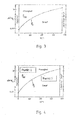
Figur 4- die Dampfdruckkurve von Wasser mit der Darstellung von zwei Punkten unterschiedlicher Druckhöhe bei denen unterschiedliche Aggregatzustände des Wassers vorliegen;
Figur 5- ein Warmformwerkzeug entsprechend der
Figur 2 in der Offenstellung mit der Darstellung des Kühlsystems; Figur 6- das Warmformwerkzeug entsprechend der
Figur 5 in der Schließstellung und Figur 7- eine Variante des Warmformwerkzeugs wie in
der Figur 5 dargestellt.
- FIG. 1
- schematically a first embodiment of a thermoforming tool in a vertical sectional view;
- FIG. 2
- schematically a second embodiment of a thermoforming tool in a vertical sectional view;
- FIG. 3
- the vapor pressure curve of water;
- FIG. 4
- the vapor pressure curve of water with the representation of two points of different pressure levels where different states of aggregation of the water are present;
- FIG. 5
- a thermoforming tool according to
FIG. 2 in the open position with the representation of the cooling system; - FIG. 6
- the thermoforming tool according to the
FIG. 5 in the closed position and - FIG. 7
- a variant of the thermoforming tool as in the
FIG. 5 shown.
Im Formraum 4 eingespannt erkennt man ein umgeformtes Formbauteil 5 aus Stahl. Der beim geschlossenen Formraum 4 zwischen Oberwerkzeug 2 und Unterwerkzeug 3 ausgebildete Werkzeugspalt ist mit 6 bezeichnet. Zur Herstellung des Formbauteils 5 ist eine Platine aus härtbarem Stahl auf eine Härtetemperatur oberhalb der Austenitisierungstemperatur erwärmt, dann in das Warmformwerkzeug 1 überführt und umgeformt worden. Im Formraum 4 eingespannt wird das Formbauteil 5 durch eine schnelle Abkühlung unterhalb der Martensit-Starttemperatur abgekühlt und gehärtet.Clamped in the
Im Oberwerkzeug 2 und im Unterwerkzeug 3 sind Versorgungsleitungen 7 vorgesehen, von denen Einspritzleitungen 8 zum Formraum 4 abgehen. Zur Kühlung des Formbauteils 5 wird Kühlmittel KM, in der Regel Wasser, von den Versorgungsleitungen 7 über die Einspritzleitungen 8 in den Formraum 4 bzw. den Werkzeugspalt 6 und in zwischen dem Formbauteil 5 und den Kontaktflächen 9 des Formraums 4 vorhandene Luftspalte 10 eingespritzt. Zum Warmformwerkzeug 1 gehören weiterhin hier nicht dargestellte Druckerzeuger und/oder ein Druckspeicher sowie Steuer- und Regelgeräte für die Einstellung des Kühlmitteldrucks sowie der Kühlmittelmenge, der Zeitdauer der Kühlmittelzufuhr und Temperaturmesselemente.
Im Formraum 4 erfolgt eine direkte Kühlung durch Einspritzen bzw. Einpressen von Kühlmittel KM und dem Kontakt des Kühlmittels KM mit dem Formbauteil 5. Die Kühlmittelversorgung einschließlich der Versorgungsleitung 7, der Einspritzleitung 8 und der zugehörigen drucktechnischen Apparate und Geräte gehören zu einem ersten Kühlsystem. Das erste Kühlsystem arbeitet im Hochdruckbereich, wobei der Druck und der Aggregatzustand des Kühlmittels KM einstellbar sind.In the
Im Oberwerkzeug 2 und im Unterwerkzeug 3 erkennt man ferner Kühlkanäle 11. Diese gehören zu einem zweiten Kühlsystem, über welches eine indirekte Kühlung des Formbauteils 5 erfolgt. Durch die Kühlkanäle 11 wird ein Kühlmittel geführt, das die von dem warmen Formbauteil 5 an das Warmformwerkzeug 1 bzw. das Oberwerkzeug 2 und das Unterwerkzeug 3 abgegebene Wärme aufnimmt und nach außen abführt. Als Kühlmittel kommt auch hier bevorzugt Wasser zum Einsatz. Vorzugsweise wird das Kühlmittel beim zweiten Kühlsystem in einem Kühlkreislauf mit Rückkühlung geführt. Während das Kühlmittel KM im ersten Kühlsystem unter Hochdruck steht, liegt das Kühlmittel im zweiten Kühlsystem mit Betriebsdrücken von bis zu 0,6 MPa vor.In the
Das in der
Das Warmformwerkzeug 12 unterscheidet sich vom Warmformwerkzeug 1 dadurch, dass eine indirekte Kühlung entfällt und im Oberwerkzeug 2 und im Unterwerkzeug 3 keine separaten Kühlkanäle vorgesehen sind, über welche Wärme vom Warmformwerkzeug 12 abgeführt wird.The
Die
Das Warmformwerkzeug 12 weist, wie vorstehend beschrieben, ein Oberwerkzeug 2 und ein Unterwerkzeug 3 auf, die relativ zueinander verlagerbar sind und zwischen denen ein Formraum 4 ausgebildet ist.As described above, the
Im Oberwerkzeug 2 und im Unterwerkzeug 3 sind Versorgungsleitungen 7 vorgesehen, von denen Einspritzleitungen 8 abgehen, die in den Formraum 4 münden. Das Kühlmittel KM wird über ein Kühlsystem KS bereitgestellt. Zum Kühlsystem KS gehören Druckerzeuger 13 und ein Druckspeicher 14 nebst steuer- und regeltechnischen Apparaten und Geräten sowie Absperrorgane und eine Vorfüllpumpe 15.In the
Im hier dargestellten Ausführungsbeispiel weist das Kühlsystem KS zwei Druckerzeuger 13 auf in Form von Kolben-Zylinder-Einheiten 16, 17. Diese sind antriebstechnisch mit dem Warmformwerkzeug 12 gekoppelt und werden durch das Oberwerkzeug 2 betätigt. Die Kolben-Zylinder-Einheiten 16, 17 bestehen jeweils im Wesentlichen aus einem Zylinder 18 mit einem darin geführt verlagerbaren Kolben 19 sowie einer Kolbenstange 20, die mechanisch mit dem Oberwerkzeug 2 in Verbindung steht. Die Kolben-Zylinder-Einheiten 16, 17 sind untereinander synchronisiert, wobei die Zylinderräume 21 kühlmittelleitend kommunizieren. Durch die Kommunikation der Drucksysteme auf allen Seiten kann insbesondere bei einer Fehlfunktion, wie zum Beispiel einer Undichtigkeit in einem der Druckhaltesysteme eine Verkeilung der Presse unterbunden werden.In the exemplary embodiment illustrated here, the cooling system KS has two
Die Vorfüllpumpe 15 versorgt das Kühlsystem KS mit Kühlmittel KM und sorgt für den nötigen Vordruck. Durch die Vorfüllpumpe 15 wird das Kühlmittel KM über eine Zuführleitung 22 in den Zylinderraum 21 der Kolben-Zylinder-Einheit 16 überführt (Pfeil P1. In die Zuführleitung 22 ist ein Rückschlagventil 23 integriert. Das Rückschlagventil 23 erlaubt den freien Durchfluss des Kühlmittels KM in Richtung zum Druckerzeuger 13 bzw. der Kolben-Zylinder-Einheit 16 und sperrt ihn in der umgekehrten Richtung. In die Zuführleitung 22 zwischen Vorfüllpumpe 15 und Rückschlagventil 23 ist des Weiteren ein Überdruckventils 30 integriert.The
Die Vorfüllpumpe 15 liefert kontinuierlich Kühlmittel KM in die Druckerzeuger 13. Die Vorfüllpumpe 15 kann kontinuierlich laufen, was die Standzeit erhöht, weil die An- und Abschaltvorgänge minimiert werden können.The
Von der Kolben-Zylinder-Einheit 16 wird das Kühlmittel KM über eine Hauptversorgungsleitung 24 in die Versorgungsleitungen 7 im Oberwerkzeug 2 und im Unterwerkzeug 3 überführt. In der Hauptversorgungsleitung 24 ist ein Schließventil 25 angeordnet, über welches die Zufuhr von Kühlmittel KM zum Warmformwerkzeug 12 geöffnet bzw. geschlossen werden kann.From the piston-
Der Druckspeicher 14 ist an die Hauptversorgungsleitung 24 angeschlossen. In die Hauptversorgungsleitung 24 ist zwischen dem Druckerzeuger 13 bzw. der Kolben-Zylinder-Einheit 16 und dem Druckspeicher 14 vorgeschaltet ein Überdruckventil 26 und ein Rückschlagventil 27 integriert.The
Der Druckspeicher 14 ist ausgeführt als Blasenspeicher und fungiert als Volumenpuffer und Energiespeicher. Der Druckspeicher 14 besteht aus einem hochfesten Stahlbehälter 28. Im Stahlbehälter 28 ist eine geschlossene, elastische Speicherblase 29 integriert. Die Speicherblase 29 ist mit Gas, in der Regel Stickstoff, befüllt. Durch die Speicherblase 29 werden das Gas und das Kühlmittel KM voneinander getrennt.The
Auch wenn in dem hier erläuterten Ausführungsbeispiel nur ein Druckspeicher 14 nebst Steuer- und Ventilorganen dargestellt ist, ist in der Praxis eine symmetrische Auslegung des Kühlsystems KS zweckmäßig. Demnach ist auch der in der Bildebene links dargestellte Druckerzeuger 13 in Form der Kolben-Zylinder-Einheit 17 mit den vorerläuterten Ventilen sowie einem Druckspeicher 14 ausgerüstet sowie mit Leitungen zum Überführen des Kühlmittels KM in die Versorgungsleitungen 7.Although only one
Die Arbeitsweise und das Funktionsprinzip zur Herstellung von gehärteten Formbauteilen werden im Folgenden beschrieben.The mode of operation and the operating principle for the production of hardened molded components are described below.
Die
Eine Metallplatine, insbesondere eine Platine aus härtbarem Stahl, wird bis auf eine Temperatur im spezifischen Austenitisierungstemperaturbereich des Werkstoffs erwärmt und anschließend in den Formraum 4 des Warmformwerkzeugs 12 auf das Unterwerkzeug 3 aufgelegt.A metal plate, in particular a plate made of hardenable steel, is heated to a temperature in the specific austenitizing temperature range of the material and then placed in the
Das Warmformwerkzeug 12 wird geschlossen. Hierzu wird das Oberwerkzeug 2 nach unten in Richtung zum Unterwerkzeug 3 bewegt. Bei der Schließbewegung werden die Kolben 19 der Kolben-Zylinder-Einheiten 16, 17 im Zylinder 18 abwärts bewegt. Hierbei wird Kraft auf das Kühlmittel KM in den Zylinderräumen 21 der Kolben-Zylinder-Einheiten 16, 17 ausgeübt, was zu einem Druckanstieg führt. Das Kühlmittel KM wird aus den Zylindern 18 über die Hauptversorgungsleitung 24 in Richtung zum Warmformwerkzeug 12 in den Druckspeicher 14 gedrückt (Pfeil P2). In der Praxis kann der Blasenvordruck bis zu 25 MPa, beispielsweise 13 MPa, betragen. Der Druck in den Druckspeichern 14 kann variieren, da diese während des Kühlmittelversorgungszyklusses nicht immer vollständig entleert werden. Zur Verhinderung eines Überdrucks im Druckspeicher 14 ist das Überdruckventil 26 vorgesehen. Das Rückschlagventil 27 verhindert einen Rückfluss vom Druckspeicher 14 in Richtung des vorgeschalteten Druckerzeugers 13.The
Es hat sich gezeigt, dass bei einem Vordruck von kleiner als 6 MPa eine unvollständige Wärmeübertragung zu einer signifikanten Verringerung der Abkühlung des Werkstücks und damit der Festigkeit des fertigen Formbauteils 5 führt.It has been found that incomplete heat transfer at a pre-pressure of less than 6 MPa leads to a significant reduction in the Cooling of the workpiece and thus the strength of the
Durch Schließen des Warmformwerkzeugs 12 wird die Platine im warmen Zustand umgeformt. Nach Beendigung der Schließbewegung ist das Formbauteil 5 fertig geformt, der Umformvorgang also abgeschlossen. Mit Beendigung der Schließbewegung wird das Schließventil 25 geöffnet und Kühlmittel KM wird durch Entspannen des Druckspeichers 14 über die Hauptversorgungsleitung 24 sowie die Versorgungsleitungen 7 und die Einspritzleitungen 8 in den Formraum 4 überführt (Pfeil P3).By closing the
Das Kühlmittel KM flutet die Luftspalte 10 zwischen dem Formbauteil 5 und den Kontaktflächen 9 des Formraums 4. Es kommt zum unmittelbaren Kontakt des Kühlmittels KM mit dem Formbauteil 5 und dem Oberwerkzeug 2 sowie dem Unterwerkzeug 3 bzw. den Kontaktflächen 9, wodurch eine direkte Kühlung des Formbauteils 5 und der damit einhergehenden Härtung erfolgt. Hierbei kommt es zu einem teilweisen Verdampfen des Kühlmittels. Der Druckspeicher 14 stellt einen Gegendruck von mindestens 0,5 MPa, vorzugsweise höher, sicher, um ein weiteres Einspritzen und Aufrechterhalten des Drucks des Kühlmittels KM zu gewährleisten.The coolant KM flows through the
Das gebrauchte Kühlmittel KM läuft aus dem Warmformwerkzeug 12 ab und wird in einer Auffangwanne aufgenommen und/oder über eine Sammelrinne abgeführt.The used coolant KM runs out of the
Nach dem Umformen bleibt das Warmformwerkzeug 12 kurz für die benötigte Haltezeit zur Sicherstellung der Gefügeumwandlung zum Härten geschlossen. Anschließend wird das Schließventil 25 geschlossen und das Warmformwerkzeug 12 fährt auseinander, so dass der Zyklus von neuem beginnen kann.After forming, the
Das erfindungsgemäß vorgesehene Kühlsystem KS ermöglicht ein sehr schnelles Einspritzen von Kühlmittel KM ohne Verzögerung im Druckaufbau. Vorteilhaft hierzu sind insbesondere die kurzen Kühlmittelwege, weil das Kühlsystem KS im Warmformwerkzeug 12 bzw. unmittelbar in räumlicher Nähe des Warmformwerkzeugs 12 angeordnet ist. Die Integration des Kühlsystems KS in das Warmformwerkzeug 12 führt zu einem wesentlich reduzierten Platzbedarf. Durch die Integration des Kühlsystems KS in das Warmformwerkzeug 12 ist auch eine Mobilität des Warmformwerkzeugs 12 möglich. Das Warmformwerkzeug 12 kann in verschiedenen Pressen genutzt werden. Ein Umrüsten des Warmformwerkzeugs 12 von einer Presse zu einer anderen Presse erfolgt komplett mit Oberwerkzeug 2 und Unterwerkzeug 3 einschließlich Kühlsystem KS.The inventively provided cooling system KS allows a very fast injection of coolant KM without delay in pressure build-up. Advantageous for this purpose are, in particular, the short coolant paths, because the cooling system KS in the hot forming
Anlagentechnisch zeichnet sich das Kühlsystem KS weiterhin dadurch aus, dass kaum Druckschwankungen im System festzustellen sind.In terms of plant technology, the cooling system KS continues to be characterized by the fact that there are hardly any pressure fluctuations in the system.
Das Warmformwerkzeug 12, wie in der
Nachfolgend sind das Grundprinzip und vier mögliche Ausführungsbeispiele der Kühlung des Formbauteils in einem Warmformwerkzeug 1 bzw. 12 erläutert.The basic principle and four possible exemplary embodiments of the cooling of the molded component in a
Die apparative Ausgestaltung des Warmformwerkzeug 1 oder 12 ermöglicht es, dass das Kühlmittel KM mit einem Druck pKM oberhalb des Dampfdrucks pD des Kühlmittels KM in den Formraum 4 und in den Werkzeugspalt 6 eingebracht wird. Dies gewährleistet eine stabile Flüssigkeitsphase des Kühlmittels KM. Hierdurch wird ein hoher Wärmeübergang bzw. eine hohe Wärmeabfuhr gewährleistet und damit eine sehr gute Kühlung. Fertigungs- und/oder verschleißbedingte Luftspalte 10 zwischen der Kontaktfläche 9 des Formraums 4 und dem Formbauteil 5 werden durch das Kühlmittel KM geschlossen. Da das Kühlmittel KM, vorliegend Wasser, unter einem hohen Druck pKM oberhalb des Dampfdrucks pD steht, wird ein Verdampfen beim Kontakt mit der heißen Bauteiloberfläche des Formbauteils 5 verhindert. Die Kühlung erfolgt gleichmäßig über die gesamte Formbauteiloberfläche. Zonen schlechter Wärmeleitung durch Dampfbildung werden vermieden.
Durch die zeitliche Steuerung von Einspritzanfang und Einspritzende sowie die Druckhöhe kann die Bauteilhärte gezielt gesteuert werden. Die Mindesthärte bildet hierbei die Härte, die bei einer bestimmten Zuhaltezeit ohne Einspritzkühlung in dem Formbauteil erreicht wird, bis hin zur maximalen Härte, die von den Werkstoffeigenschaften und dem Legierungskonzept des Bauteilwerkstoffes abhängt. Die Steuerung von Einspritzanfang und Einspritzende ist auch durch eine Onlinemessung der Formbauteiltemperatur im oder vergleichend am Werkzeug möglich. Hierzu wird die Bauteiltemperatur TB des Formbauteils 5 im Formraum 4 gemessen. Weiterhin kann die Werkzeugtemperatur TW im Bereich der Kontaktflächen 9 des Formraums 4 gemessen werden. Der Anfangszeitpunkt TA (Einspritzanfang) und der Endzeitpunkt TE (Einspritzende) der Kühlmittelzufuhr wird in Abhängigkeit von der Bauteiltemperatur TB und/oder der Werkzeugtemperatur TW gesteuert.By controlling the timing of injection start and end of injection and the pressure level, the component hardness can be controlled specifically. The minimum hardness in this case forms the hardness that is achieved in the mold component at a certain holding time without injection cooling, up to the maximum hardness, which depends on the material properties and the alloy concept of the component material. The control of injection start and end of injection is also possible by an online measurement of the mold component temperature in or comparatively on the tool. For this purpose, the component temperature T B of the
Durch die möglichen extrem kurzen Zuhaltezeiten des Warmformwerkzeugs 1 bzw. 12 lassen sich partiell gehärtete Formbauteile 5 herstellen, in dem nur bestimmte Bereiche des Formbauteils 5 im Formraum 4 mit Kühlmittel KM beaufschlagt werden. Es erfolgt eine sektionale Kühlmitteleinspritzung in ansteuerbare Bereiche des Formraums 4 und korrespondierend hierzu auf die Bereiche des Formbauteils 5, die nach der Entnahme hart sein sollen. In den Bereichen des Formbauteils 5, die nach dem Warmform- und Presshärtvorgang eine geringere Festigkeit haben sollen, kann die Abkühlung noch zusätzlich durch den Einsatz von Mitteln zur Beeinflussung der Wärmeübertragung verzögert werden, die in den Kontaktflächen 9 des Formraums 4 angeordnet sind. Bei solchen Mitteln kann es sich beispielsweise um Heizelemente, Freimachungen, Luftspalte, Einsätze aus Materialien mit geringerer oder höherer Wärmeleitfähigkeit oder Keramikeinsätze handeln.Due to the possible extremely short closing times of the
Aus dem Warmformwerkzeug 1 bzw. 12 wird ein Formbauteil 5 entnommen, welches zumindest zwei Zonen bzw. Bereiche aufweist, die voneinander verschiedene Temperaturen haben. Dieses Formbauteil 5 wird zur weiteren Abkühlung in einer gesonderten Abkühlstation fixiert gehalten. Diese Maßnahme wirkt sich vorteilhaft auf die definierte Abkühlung der weichen, nicht oder weniger stark gehärteten Bereiche aus und verhindert ein Verziehen des Formbauteils 5.From the
Durch eine Variation der Einspritzdauer in Verbindung mit einer Variation des Einspritzdruckes pKM können frei unterschiedliche Wärmeübergangskoeffizienten über ein Formbauteil 5 verteilt eingestellt werden. Je nach Einspritzdruck ist es möglich, im Formraum 4 bzw. im Werkzeugspalt 6 zwischen Oberwerkzeug 2 und Unterwerkzeug 3 eine Wasserschicht mit einer guten Wärmeleitung und einen Nassdampf mit einer anderen, schlechteren Wärmeleitfähigkeit zu erzeugen. Die beiden Betriebspunkte des Kühlmitteldrucks sind in der
Durch ein Betreiben der Hochdruckeinspritzkühlung im Nassdampfbereich können Warmformwerkzeuge günstig ohne eine konventionelle Kühlung aufgebaut werden. Es kann folglich ein Warmformwerkzeug 12 wie in
Beim Betreiben im Nassdampfbereich wird die Wärmeenergie aus dem Formbauteil flächig dazu genutzt das Wasser aus der flüssigen Phase in die gasförmige Phase zu überführen. Um keinen geschlossenen Wasserfilm im Werkzeugspalt 6 zu erzeugen, wird der Einspritzdruck pKM zeitgesteuert oder über eine Temperaturmessung am Formbauteil 5 angepasst. Alternativ wird vergleichend die Werkzeugtemperatur TW am Warmformwerkzeug 1 bzw. im Bereich der Kontaktflächen 9 des Formraums 4 gemessen und ständig an den Dampfdruck pD angepasst.When operating in the wet steam region, the heat energy from the mold component is used in a planar manner to transfer the water from the liquid phase into the gaseous phase. In order not to produce a closed water film in the
Bei den vorerläuterten Ausführungsbeispielen 1 bis 4 kann vorgesehen sein, das Überdruckventil 26 zusätzlich zu indirekten Verschleißanzeige des Warmformwerkzeugs 1 bzw. 12 zu nutzen. Dazu wird die Ablassmenge am Überdruckventil 26 messtechnisch durch die Mess- und Auswerteeinheit ME erfasst und ausgewertet. Damit kann im laufenden Betrieb über die Zeit eine Aussage über die Abnutzung des Formwerkzeugs 1, 12 getroffen werden, um rechtzeitig Werkzeugüberholungen bzw. -instandhaltungen einplanen und durchführen zu können.In the above-described
- 1 -1 -
- WarmformwerkzeugThermoforming tool
- 2 -2 -
- Oberwerkzeugupper tool
- 3 -3 -
- Unterwerkzeuglower tool
- 4 -4 -
- Formraumcavity
- 5 -5 -
- Formbauteilmold component
- 6 -6 -
- Werkzeugspalttool gap
- 7 -7 -
- Versorgungsleitungsupply line
- 8 -8th -
- EinspritzleitungInjection line
- 9 -9 -
- Kontaktflächecontact area
- 10 -10 -
- Luftspaltair gap
- 11 -11 -
- Kühlkanalcooling channel
- 12-12-
- WarmformwerkzeugThermoforming tool
- 13 -13 -
- Druckerzeugerpressure generator
- 14 -14 -
- Druckspeicheraccumulator
- 15 -15 -
- Vorfüllpumpepriming pump
- 16 -16 -
- Kolben-Zylinder-EinheitPiston-cylinder unit
- 17 -17 -
- Kolben-Zylinder-EinheitPiston-cylinder unit
- 18 -18 -
- Zylindercylinder
- 19 -19 -
- Kolbenpiston
- 20 -20 -
- Kolbenstangepiston rod
- 21 -21 -
- Zylinderraumcylinder space
- 22 -22 -
- Zuführleitungfeed
- 23 -23 -
- Rückschlagventilcheck valve
- 24 -24 -
- HauptversorgungsleitungMain supply line
- 25 -25 -
- Schließventilclosing valve
- 26 -26 -
- ÜberdruckventilPressure relief valve
- 27 -27 -
- Rückschlagventilcheck valve
- 28 -28 -
- Stahlbehältersteel containers
- 29 -29 -
- Speicherblasebladder
- 30 -30 -
- ÜberdruckventilPressure relief valve
- KM -KM -
- Kühlmittelcoolant
- KS -KS -
- Kühlsystemcooling system
- pKM -p KM -
- KühlmitteldruckCoolant pressure
- pD -p D -
- Dampfdruckvapor pressure
- TB -T B -
- Bauteiltemperaturcomponent temperature
- TW -T W -
- Werkzeugtemperaturmold temperature
- TA -T A -
- Anfangszeitpunkt (Einspritzanfang)Start time (start of injection)
- TE -T E -
- Endzeitpunkt (Einspritzende)End time (end of injection)
- P1 -P1 -
- Pfeilarrow
- P2 -P2 -
- Pfeilarrow
- P3 -P3 -
- Pfeilarrow
- ME -ME -
- Mess- und AuswerteeinheitMeasuring and evaluation unit
Claims (13)
Applications Claiming Priority (2)
| Application Number | Priority Date | Filing Date | Title |
|---|---|---|---|
| DE102010012579A DE102010012579B3 (en) | 2010-03-23 | 2010-03-23 | Method and device for producing hardened molded components |
| EP11159354.7A EP2371465B1 (en) | 2010-03-23 | 2011-03-23 | Method and device for producing hardened moulded components |
Related Parent Applications (3)
| Application Number | Title | Priority Date | Filing Date |
|---|---|---|---|
| EP11159354.7 Division | 2011-03-23 | ||
| EP11159354.7A Division-Into EP2371465B1 (en) | 2010-03-23 | 2011-03-23 | Method and device for producing hardened moulded components |
| EP11159354.7A Division EP2371465B1 (en) | 2010-03-23 | 2011-03-23 | Method and device for producing hardened moulded components |
Publications (3)
| Publication Number | Publication Date |
|---|---|
| EP2446978A1 true EP2446978A1 (en) | 2012-05-02 |
| EP2446978B1 EP2446978B1 (en) | 2015-04-29 |
| EP2446978B8 EP2446978B8 (en) | 2015-06-24 |
Family
ID=44278990
Family Applications (2)
| Application Number | Title | Priority Date | Filing Date |
|---|---|---|---|
| EP12151528.2A Not-in-force EP2446978B8 (en) | 2010-03-23 | 2011-03-23 | Method and device for producing hardened moulded components |
| EP11159354.7A Not-in-force EP2371465B1 (en) | 2010-03-23 | 2011-03-23 | Method and device for producing hardened moulded components |
Family Applications After (1)
| Application Number | Title | Priority Date | Filing Date |
|---|---|---|---|
| EP11159354.7A Not-in-force EP2371465B1 (en) | 2010-03-23 | 2011-03-23 | Method and device for producing hardened moulded components |
Country Status (5)
| Country | Link |
|---|---|
| US (1) | US8707751B2 (en) |
| EP (2) | EP2446978B8 (en) |
| CN (1) | CN102198465B (en) |
| DE (1) | DE102010012579B3 (en) |
| RU (1) | RU2467076C1 (en) |
Cited By (1)
| Publication number | Priority date | Publication date | Assignee | Title |
|---|---|---|---|---|
| WO2016008720A1 (en) * | 2014-07-18 | 2016-01-21 | Bayerische Motoren Werke Aktiengesellschaft | Moulding tool for producing hot-formed components |
Families Citing this family (31)
| Publication number | Priority date | Publication date | Assignee | Title |
|---|---|---|---|---|
| DE102010027554A1 (en) * | 2010-07-19 | 2012-01-19 | Thyssenkrupp Umformtechnik Gmbh | Forming tool and method for hot forming and partial press hardening of a work piece made of sheet steel |
| JP5679057B2 (en) | 2011-06-29 | 2015-03-04 | トヨタ自動車株式会社 | Hot press equipment |
| DE102011108912A1 (en) * | 2011-07-28 | 2013-01-31 | Volkswagen Aktiengesellschaft | Segmented press hardening tool |
| US20140096585A1 (en) * | 2011-08-17 | 2014-04-10 | Kirchhoff Automotive Deutschland Gmbh | Press Hardening Tool |
| DE102011053698C5 (en) | 2011-09-16 | 2017-11-16 | Benteler Automobiltechnik Gmbh | Process for the manufacture of structural and chassis components by thermoforming and heating station |
| CN102430628A (en) * | 2011-09-30 | 2012-05-02 | 大连理工大学 | Thermal forming method for multilayer metal composite boards |
| EP2583766B1 (en) * | 2011-10-21 | 2019-04-17 | EDAG Werkzeug + Karosserie GmbH | Forming with cooling |
| DE102011055643A1 (en) | 2011-11-23 | 2013-05-23 | Thyssenkrupp Steel Europe Ag | Method and forming tool for hot forming and press hardening of workpieces made of sheet steel, in particular galvanized workpieces made of sheet steel |
| DE102012104734A1 (en) | 2012-05-31 | 2013-12-05 | Outokumpu Nirosta Gmbh | Method and device for producing formed sheet metal parts at cryogenic temperature |
| CN102974683B (en) * | 2012-12-07 | 2014-07-09 | 上海宝钢型钢有限公司 | Ultrahigh strength open section hot roll forming process and device |
| JP6093630B2 (en) * | 2013-04-12 | 2017-03-08 | 東プレ株式会社 | Manufacturing method of hot press products |
| TWI590887B (en) * | 2013-09-12 | 2017-07-11 | Nippon Steel & Sumitomo Metal Corp | Method for cooling by hot press forming of sheet steel and hot press forming device for sheet steel |
| WO2015124404A1 (en) | 2014-02-24 | 2015-08-27 | Bayerische Motoren Werke Aktiengesellschaft | Forming tool for shaping a workpiece, and method for positioning a temperature control device on a forming tool |
| KR101588740B1 (en) | 2014-06-18 | 2016-02-12 | 현대자동차 주식회사 | Device and method for hot stamping |
| DE102014109553A1 (en) * | 2014-07-08 | 2016-01-14 | Thyssenkrupp Ag | Hardening tool and method for producing hardened profile moldings |
| HUE039096T2 (en) * | 2015-03-26 | 2018-12-28 | Weba Werkzeugbau Betr Gmbh | Method and device for producing a partially cured moulded part |
| JP6526459B2 (en) * | 2015-03-26 | 2019-06-05 | 株式会社ワイテック | METHOD AND APPARATUS FOR FORMING TUBULAR BODY |
| EP3088092B1 (en) | 2015-04-30 | 2017-06-07 | Benteler Automobiltechnik GmbH | Hot forming and press hardening tool and method for operating the hot forming and press hardening tool |
| CA2993957A1 (en) * | 2015-07-30 | 2017-02-02 | Magna International, Inc. | Stamping die |
| PL3156506T3 (en) * | 2015-10-15 | 2019-06-28 | Automation, Press And Tooling, A.P. & T Ab | Partial radiation heating method for producing press hardened parts and arrangement for such production |
| DE102016102344B4 (en) * | 2016-02-10 | 2020-09-24 | Voestalpine Metal Forming Gmbh | Method and device for producing hardened steel components |
| DE102016102322B4 (en) * | 2016-02-10 | 2017-10-12 | Voestalpine Metal Forming Gmbh | Method and device for producing hardened steel components |
| JP6357196B2 (en) * | 2016-07-19 | 2018-07-11 | 東亜工業株式会社 | Hot press device, hot press method, and automobile body part manufacturing method |
| CN106271363A (en) * | 2016-08-19 | 2017-01-04 | 天津森马机械制造有限公司 | A kind of feed dog entirety fine adjusting method, instrument and equipment |
| CN108237181B (en) * | 2016-12-23 | 2019-09-13 | 财团法人金属工业研究发展中心 | Forming device |
| DE102017116556B4 (en) * | 2017-07-21 | 2022-02-03 | Leiber Group Gmbh & Co. Kg | Forging processes, in particular lightweight alloy forging processes |
| US20210087644A1 (en) * | 2018-02-06 | 2021-03-25 | Integrated Heat Treating Solutions, Llc | High pressure instantaneously uniform quench to control part properties |
| KR20210079294A (en) * | 2018-09-24 | 2021-06-29 | 팔스 베지츠 게엠베하 | A cost-effective method for obtaining geometrically complex pieces |
| JP7147586B2 (en) * | 2019-01-24 | 2022-10-05 | マツダ株式会社 | Hot press processing equipment |
| JP7120044B2 (en) * | 2019-01-24 | 2022-08-17 | マツダ株式会社 | Hot press processing equipment |
| JP7151507B2 (en) * | 2019-01-24 | 2022-10-12 | マツダ株式会社 | Hot press processing equipment |
Citations (13)
| Publication number | Priority date | Publication date | Assignee | Title |
|---|---|---|---|---|
| DE2452486A1 (en) | 1973-11-06 | 1975-05-07 | Norrbottens Jaernverk Ab | PROCESS FOR MANUFACTURING A WORKPIECE FROM HARDENED STEEL |
| DE2603618A1 (en) | 1975-06-05 | 1976-12-23 | Kenebuc Galt Ltd | Heating and quenching steel parts such as Belleville springs - using quenching press contg. dies which clamp spring |
| DE19520138A1 (en) * | 1995-06-01 | 1996-12-05 | Wsp Ingenieur Gmbh | Cooling channel for heat treated plate and sheet |
| EP1195208A2 (en) * | 2000-10-07 | 2002-04-10 | DaimlerChrysler AG | Method to produce locally reinforced sheet metal |
| US6443214B1 (en) * | 1999-12-07 | 2002-09-03 | Honda Giken Kogyo Kabushiki Kaisha | Method for heat treating mold cast product |
| JP2002282951A (en) | 2001-03-22 | 2002-10-02 | Toyota Motor Corp | Method for hot press forming metal plate and apparatus therefor |
| DE102005028010B3 (en) | 2005-06-16 | 2006-07-20 | Benteler Automobiltechnik Gmbh | Shaping and hardening heated steel workpiece, e.g. sheet, using press with lower mold tool located in liquid bath, minimizing or eliminating holding time for hardening workpiece in closed mold |
| WO2007084089A2 (en) * | 2006-01-18 | 2007-07-26 | Mehmet Terziakin | Method for delaying of cooling and hardening of desired zones of a sheet during a hot metal stamping process |
| EP2289694A2 (en) * | 2008-07-25 | 2011-03-02 | Hyundai Steel Company | Press-cure mold cooling device |
| DE102010011087A1 (en) | 2010-03-12 | 2011-09-15 | Volkswagen Ag | Method for producing a coolable molding tool |
| WO2011115539A1 (en) | 2010-03-16 | 2011-09-22 | Gestamp Hardtech Ab | Press hardening plant and a method of press hardening a steel sheet blank |
| EP2392419A1 (en) | 2009-01-23 | 2011-12-07 | Fukai Seisakusho Co., Ltd. | Method of press-forming of embossed steel sheet |
| DE102010048209B3 (en) | 2010-10-15 | 2012-01-05 | Benteler Automobiltechnik Gmbh | Method for producing a hot-formed press-hardened metal component |
Family Cites Families (18)
| Publication number | Priority date | Publication date | Assignee | Title |
|---|---|---|---|---|
| US1457772A (en) * | 1920-01-12 | 1923-06-05 | George H Forsyth | Forming and tempering disk wheels |
| US2762734A (en) * | 1952-09-29 | 1956-09-11 | North American Aviation Inc | Process and apparatus for forming and stress relieving metal |
| SU376460A1 (en) * | 1970-12-14 | 1973-04-05 | STAMP FOR HANGING LARGE DETAILS | |
| SU1235607A1 (en) * | 1982-10-11 | 1986-06-07 | Физико-технический институт АН БССР | Method of cooling hot-forming dies |
| SU1194897A1 (en) * | 1984-04-09 | 1985-11-30 | Куйбышевский ордена Трудового Красного Знамени политехнический институт им.В.В.Куйбышева | Die for hardening articles |
| RU2033288C1 (en) * | 1991-04-19 | 1995-04-20 | Молдавский металлургический завод | Apparatus for cooling rolled bars, produced by dividing rolling process |
| DE19943272A1 (en) * | 1999-09-10 | 2001-03-15 | Schuler Pressen Gmbh & Co | Shaping machine has cooling device with at least one cooling channel connected to the base frame(s) or to the tool in a thermally conducting manner |
| JP3863874B2 (en) * | 2003-10-02 | 2006-12-27 | 新日本製鐵株式会社 | Hot press forming apparatus and hot press forming method for metal plate material |
| US7254977B2 (en) * | 2004-01-20 | 2007-08-14 | Pullman Industries, Inc. | Coolant delivery system and continuous fabrication apparatus which includes the system |
| TWI248863B (en) * | 2004-02-12 | 2006-02-11 | Mitsubishi Heavy Ind Ltd | Apparatus and method for mold temperature adjustment, and mold temperature control unit |
| DE102005025026B3 (en) * | 2005-05-30 | 2006-10-19 | Thyssenkrupp Steel Ag | Production of metal components with adjacent zones of different characteristics comprises press-molding sheet metal using ram and female mold, surfaces of ram which contact sheet being heated and time of contact being controlled |
| DE102006042830B3 (en) | 2006-09-08 | 2007-10-31 | Benteler Automobiltechnik Gmbh | Press-quenched steel component production comprises temporarily spraying blank with cooling medium by feeding medium through feed channels into die before closing die |
| US7730753B2 (en) * | 2007-02-06 | 2010-06-08 | Gm Global Technology Operations, Inc. | Lubricant for elevated temperature forming |
| RU2351429C1 (en) * | 2007-06-04 | 2009-04-10 | Институт машиноведения и металлургии ДВО РАН | Refrigeration method of mold with receiving of sections and installation for its implementation |
| DE102007041012A1 (en) | 2007-08-29 | 2009-03-05 | Linde + Wiemann Gmbh Kg | Hot forming method for partially hot semi-finished product i.e. solid and rigid tool component, involves opening tool in sections such that gap is formed between forming surfaces of forming units, and feeding cooling agent into gap |
| DE102007062524B3 (en) | 2007-12-20 | 2009-02-26 | Benteler Automobiltechnik Gmbh | Method for the production of hybrid component useful in a cross girder for an instrument panel of a motor vehicle, comprises fixing a support body in a tube component, and inserting the tube component in an injection molding tool |
| WO2010061007A1 (en) | 2008-11-03 | 2010-06-03 | Fundacion Labein | Method for hardening a component obtained by hot-forging and device used |
| CN101486061B (en) * | 2009-02-24 | 2010-08-11 | 山东大学 | Thermoforming, hole-punching and edge-cutting integrated technique and mold of high-duty steel part |
-
2010
- 2010-03-23 DE DE102010012579A patent/DE102010012579B3/en active Active
-
2011
- 2011-03-14 CN CN201110060176.2A patent/CN102198465B/en active Active
- 2011-03-17 US US13/050,500 patent/US8707751B2/en not_active Expired - Fee Related
- 2011-03-22 RU RU2011110876/02A patent/RU2467076C1/en not_active IP Right Cessation
- 2011-03-23 EP EP12151528.2A patent/EP2446978B8/en not_active Not-in-force
- 2011-03-23 EP EP11159354.7A patent/EP2371465B1/en not_active Not-in-force
Patent Citations (13)
| Publication number | Priority date | Publication date | Assignee | Title |
|---|---|---|---|---|
| DE2452486A1 (en) | 1973-11-06 | 1975-05-07 | Norrbottens Jaernverk Ab | PROCESS FOR MANUFACTURING A WORKPIECE FROM HARDENED STEEL |
| DE2603618A1 (en) | 1975-06-05 | 1976-12-23 | Kenebuc Galt Ltd | Heating and quenching steel parts such as Belleville springs - using quenching press contg. dies which clamp spring |
| DE19520138A1 (en) * | 1995-06-01 | 1996-12-05 | Wsp Ingenieur Gmbh | Cooling channel for heat treated plate and sheet |
| US6443214B1 (en) * | 1999-12-07 | 2002-09-03 | Honda Giken Kogyo Kabushiki Kaisha | Method for heat treating mold cast product |
| EP1195208A2 (en) * | 2000-10-07 | 2002-04-10 | DaimlerChrysler AG | Method to produce locally reinforced sheet metal |
| JP2002282951A (en) | 2001-03-22 | 2002-10-02 | Toyota Motor Corp | Method for hot press forming metal plate and apparatus therefor |
| DE102005028010B3 (en) | 2005-06-16 | 2006-07-20 | Benteler Automobiltechnik Gmbh | Shaping and hardening heated steel workpiece, e.g. sheet, using press with lower mold tool located in liquid bath, minimizing or eliminating holding time for hardening workpiece in closed mold |
| WO2007084089A2 (en) * | 2006-01-18 | 2007-07-26 | Mehmet Terziakin | Method for delaying of cooling and hardening of desired zones of a sheet during a hot metal stamping process |
| EP2289694A2 (en) * | 2008-07-25 | 2011-03-02 | Hyundai Steel Company | Press-cure mold cooling device |
| EP2392419A1 (en) | 2009-01-23 | 2011-12-07 | Fukai Seisakusho Co., Ltd. | Method of press-forming of embossed steel sheet |
| DE102010011087A1 (en) | 2010-03-12 | 2011-09-15 | Volkswagen Ag | Method for producing a coolable molding tool |
| WO2011115539A1 (en) | 2010-03-16 | 2011-09-22 | Gestamp Hardtech Ab | Press hardening plant and a method of press hardening a steel sheet blank |
| DE102010048209B3 (en) | 2010-10-15 | 2012-01-05 | Benteler Automobiltechnik Gmbh | Method for producing a hot-formed press-hardened metal component |
Cited By (1)
| Publication number | Priority date | Publication date | Assignee | Title |
|---|---|---|---|---|
| WO2016008720A1 (en) * | 2014-07-18 | 2016-01-21 | Bayerische Motoren Werke Aktiengesellschaft | Moulding tool for producing hot-formed components |
Also Published As
| Publication number | Publication date |
|---|---|
| US20110232354A1 (en) | 2011-09-29 |
| US8707751B2 (en) | 2014-04-29 |
| EP2371465B1 (en) | 2015-07-01 |
| EP2371465A1 (en) | 2011-10-05 |
| EP2446978B8 (en) | 2015-06-24 |
| CN102198465B (en) | 2016-04-06 |
| RU2011110876A (en) | 2012-09-27 |
| EP2446978B1 (en) | 2015-04-29 |
| CN102198465A (en) | 2011-09-28 |
| DE102010012579B3 (en) | 2011-07-07 |
| RU2467076C1 (en) | 2012-11-20 |
Similar Documents
| Publication | Publication Date | Title |
|---|---|---|
| EP2371465B1 (en) | Method and device for producing hardened moulded components | |
| EP2595770B1 (en) | Forming tool and method for hot forming and partially press hardening a workpiece made of sheet steel | |
| DE102005028010B3 (en) | Shaping and hardening heated steel workpiece, e.g. sheet, using press with lower mold tool located in liquid bath, minimizing or eliminating holding time for hardening workpiece in closed mold | |
| EP2062987B1 (en) | Heat form press | |
| DE102014112325B4 (en) | Press forming tool with tolerance compensation | |
| EP0206100B1 (en) | Method and apparatus for making moulded articles of solid or microcellular plastic material, in particular a free-flowing reactive mixture forming polyurethane of at least two free-flowing reaction components | |
| EP2993241A1 (en) | Method and press for manufacturing cured sheet metal components, in sections at least | |
| EP2324938A1 (en) | Method and thermal recasting assembly for producing a hardened, thermally recast workpiece | |
| DE102011011013B4 (en) | Press plant for forming or processing metal components | |
| DE102014222476B4 (en) | A heat treatment apparatus for hot stamping and molding using the like | |
| EP1983063B1 (en) | Method for moulding and hardening a workpiece made from steel in a stamping machine | |
| DE10043209A1 (en) | Flexible tool for forming a workpiece | |
| EP3088092B1 (en) | Hot forming and press hardening tool and method for operating the hot forming and press hardening tool | |
| DE102011120789B4 (en) | Process for finishing a blank forming tool | |
| DE102015220842B4 (en) | Press molding apparatus and press molding method for a semi-solid metal material | |
| DE102014112320B4 (en) | Press forming tool with compensation pad | |
| WO2005021253A2 (en) | Hydraulic press and deep-drawing press | |
| EP3369569B1 (en) | Method for laminating a number of layers arranged in a stack to form a laminate composition | |
| DE102013011419A1 (en) | Press hardening a circuit board, by inserting printed circuit board into press hardening tool, and subjecting board with first pressing force and second pressing force that is applied independently to first pressing force | |
| EP3010709B1 (en) | Method for warping the machine bed and/or the press ram of a punching press and punching press | |
| DE102018209239A1 (en) | Production method for a forming tool part of a press-hardening tool | |
| EP3444098B1 (en) | Method and apparatus for cooling a tool of a thermoforming machine comprising two halves | |
| DE10016804A1 (en) | Method and device for producing components from a deep-drawn board | |
| DE102014006710B4 (en) | Process for forming a workpiece, active tool part and forming tool for carrying out the process | |
| WO2024068320A1 (en) | Device for curing sheet metal components |
Legal Events
| Date | Code | Title | Description |
|---|---|---|---|
| PUAI | Public reference made under article 153(3) epc to a published international application that has entered the european phase |
Free format text: ORIGINAL CODE: 0009012 |
|
| AC | Divisional application: reference to earlier application |
Ref document number: 2371465 Country of ref document: EP Kind code of ref document: P |
|
| AK | Designated contracting states |
Kind code of ref document: A1 Designated state(s): AL AT BE BG CH CY CZ DE DK EE ES FI FR GB GR HR HU IE IS IT LI LT LU LV MC MK MT NL NO PL PT RO RS SE SI SK SM TR |
|
| 17P | Request for examination filed |
Effective date: 20120814 |
|
| TPAC | Observations filed by third parties |
Free format text: ORIGINAL CODE: EPIDOSNTIPA |
|
| TPAB | Information related to observations by third parties deleted |
Free format text: ORIGINAL CODE: EPIDOSDTIPA |
|
| TPAC | Observations filed by third parties |
Free format text: ORIGINAL CODE: EPIDOSNTIPA |
|
| 17Q | First examination report despatched |
Effective date: 20130315 |
|
| GRAP | Despatch of communication of intention to grant a patent |
Free format text: ORIGINAL CODE: EPIDOSNIGR1 |
|
| INTG | Intention to grant announced |
Effective date: 20150113 |
|
| GRAS | Grant fee paid |
Free format text: ORIGINAL CODE: EPIDOSNIGR3 |
|
| GRAA | (expected) grant |
Free format text: ORIGINAL CODE: 0009210 |
|
| RAP1 | Party data changed (applicant data changed or rights of an application transferred) |
Owner name: BENTELER AUTOMOBILTECHNIK GMBH |
|
| REG | Reference to a national code |
Ref country code: DE Ref legal event code: R108 Ref document number: 502011006755 Country of ref document: DE |
|
| AC | Divisional application: reference to earlier application |
Ref document number: 2371465 Country of ref document: EP Kind code of ref document: P |
|
| AK | Designated contracting states |
Kind code of ref document: B1 Designated state(s): AL AT BE BG CH CY CZ DE DK EE ES FI FR GB GR HR HU IE IS IT LI LT LU LV MC MK MT NL NO PL PT RO RS SE SI SK SM TR |
|
| REG | Reference to a national code |
Ref country code: GB Ref legal event code: FG4D Free format text: NOT ENGLISH |
|
| REG | Reference to a national code |
Ref country code: CH Ref legal event code: EP |
|
| REG | Reference to a national code |
Ref country code: AT Ref legal event code: REF Ref document number: 724155 Country of ref document: AT Kind code of ref document: T Effective date: 20150515 |
|
| REG | Reference to a national code |
Ref country code: IE Ref legal event code: FG4D Free format text: LANGUAGE OF EP DOCUMENT: GERMAN |
|
| RBV | Designated contracting states (corrected) |
Designated state(s): AL AT BE BG CH CY CZ DK EE ES FI FR GB GR HR HU IE IS IT LI LT LU LV MC MK MT NL NO PL PT RO RS SE SI SK SM TR |
|
| REG | Reference to a national code |
Ref country code: DE Ref legal event code: R107 Ref document number: 502011006755 Country of ref document: DE |
|
| REG | Reference to a national code |
Ref country code: NL Ref legal event code: VDEP Effective date: 20150429 |
|
| REG | Reference to a national code |
Ref country code: LT Ref legal event code: MG4D |
|
| PG25 | Lapsed in a contracting state [announced via postgrant information from national office to epo] |
Ref country code: NL Free format text: LAPSE BECAUSE OF FAILURE TO SUBMIT A TRANSLATION OF THE DESCRIPTION OR TO PAY THE FEE WITHIN THE PRESCRIBED TIME-LIMIT Effective date: 20150429 |
|
| PG25 | Lapsed in a contracting state [announced via postgrant information from national office to epo] |
Ref country code: HR Free format text: LAPSE BECAUSE OF FAILURE TO SUBMIT A TRANSLATION OF THE DESCRIPTION OR TO PAY THE FEE WITHIN THE PRESCRIBED TIME-LIMIT Effective date: 20150429 Ref country code: NO Free format text: LAPSE BECAUSE OF FAILURE TO SUBMIT A TRANSLATION OF THE DESCRIPTION OR TO PAY THE FEE WITHIN THE PRESCRIBED TIME-LIMIT Effective date: 20150729 Ref country code: PT Free format text: LAPSE BECAUSE OF FAILURE TO SUBMIT A TRANSLATION OF THE DESCRIPTION OR TO PAY THE FEE WITHIN THE PRESCRIBED TIME-LIMIT Effective date: 20150831 Ref country code: LT Free format text: LAPSE BECAUSE OF FAILURE TO SUBMIT A TRANSLATION OF THE DESCRIPTION OR TO PAY THE FEE WITHIN THE PRESCRIBED TIME-LIMIT Effective date: 20150429 Ref country code: FI Free format text: LAPSE BECAUSE OF FAILURE TO SUBMIT A TRANSLATION OF THE DESCRIPTION OR TO PAY THE FEE WITHIN THE PRESCRIBED TIME-LIMIT Effective date: 20150429 Ref country code: ES Free format text: LAPSE BECAUSE OF FAILURE TO SUBMIT A TRANSLATION OF THE DESCRIPTION OR TO PAY THE FEE WITHIN THE PRESCRIBED TIME-LIMIT Effective date: 20150429 |
|
| PG25 | Lapsed in a contracting state [announced via postgrant information from national office to epo] |
Ref country code: LV Free format text: LAPSE BECAUSE OF FAILURE TO SUBMIT A TRANSLATION OF THE DESCRIPTION OR TO PAY THE FEE WITHIN THE PRESCRIBED TIME-LIMIT Effective date: 20150429 Ref country code: RS Free format text: LAPSE BECAUSE OF FAILURE TO SUBMIT A TRANSLATION OF THE DESCRIPTION OR TO PAY THE FEE WITHIN THE PRESCRIBED TIME-LIMIT Effective date: 20150429 Ref country code: GR Free format text: LAPSE BECAUSE OF FAILURE TO SUBMIT A TRANSLATION OF THE DESCRIPTION OR TO PAY THE FEE WITHIN THE PRESCRIBED TIME-LIMIT Effective date: 20150730 Ref country code: IS Free format text: LAPSE BECAUSE OF FAILURE TO SUBMIT A TRANSLATION OF THE DESCRIPTION OR TO PAY THE FEE WITHIN THE PRESCRIBED TIME-LIMIT Effective date: 20150829 |
|
| PG25 | Lapsed in a contracting state [announced via postgrant information from national office to epo] |
Ref country code: DK Free format text: LAPSE BECAUSE OF FAILURE TO SUBMIT A TRANSLATION OF THE DESCRIPTION OR TO PAY THE FEE WITHIN THE PRESCRIBED TIME-LIMIT Effective date: 20150429 Ref country code: EE Free format text: LAPSE BECAUSE OF FAILURE TO SUBMIT A TRANSLATION OF THE DESCRIPTION OR TO PAY THE FEE WITHIN THE PRESCRIBED TIME-LIMIT Effective date: 20150429 |
|
| PG25 | Lapsed in a contracting state [announced via postgrant information from national office to epo] |
Ref country code: RO Free format text: LAPSE BECAUSE OF NON-PAYMENT OF DUE FEES Effective date: 20150429 Ref country code: PL Free format text: LAPSE BECAUSE OF FAILURE TO SUBMIT A TRANSLATION OF THE DESCRIPTION OR TO PAY THE FEE WITHIN THE PRESCRIBED TIME-LIMIT Effective date: 20150429 Ref country code: CZ Free format text: LAPSE BECAUSE OF FAILURE TO SUBMIT A TRANSLATION OF THE DESCRIPTION OR TO PAY THE FEE WITHIN THE PRESCRIBED TIME-LIMIT Effective date: 20150429 Ref country code: SK Free format text: LAPSE BECAUSE OF FAILURE TO SUBMIT A TRANSLATION OF THE DESCRIPTION OR TO PAY THE FEE WITHIN THE PRESCRIBED TIME-LIMIT Effective date: 20150429 |
|
| PLBE | No opposition filed within time limit |
Free format text: ORIGINAL CODE: 0009261 |
|
| STAA | Information on the status of an ep patent application or granted ep patent |
Free format text: STATUS: NO OPPOSITION FILED WITHIN TIME LIMIT |
|
| REG | Reference to a national code |
Ref country code: FR Ref legal event code: PLFP Year of fee payment: 6 |
|
| 26N | No opposition filed |
Effective date: 20160201 |
|
| PG25 | Lapsed in a contracting state [announced via postgrant information from national office to epo] |
Ref country code: IT Free format text: LAPSE BECAUSE OF FAILURE TO SUBMIT A TRANSLATION OF THE DESCRIPTION OR TO PAY THE FEE WITHIN THE PRESCRIBED TIME-LIMIT Effective date: 20150429 |
|
| PG25 | Lapsed in a contracting state [announced via postgrant information from national office to epo] |
Ref country code: SI Free format text: LAPSE BECAUSE OF FAILURE TO SUBMIT A TRANSLATION OF THE DESCRIPTION OR TO PAY THE FEE WITHIN THE PRESCRIBED TIME-LIMIT Effective date: 20150429 |
|
| PGFP | Annual fee paid to national office [announced via postgrant information from national office to epo] |
Ref country code: FR Payment date: 20160321 Year of fee payment: 6 |
|
| PG25 | Lapsed in a contracting state [announced via postgrant information from national office to epo] |
Ref country code: BE Free format text: LAPSE BECAUSE OF NON-PAYMENT OF DUE FEES Effective date: 20160331 |
|
| PG25 | Lapsed in a contracting state [announced via postgrant information from national office to epo] |
Ref country code: LU Free format text: LAPSE BECAUSE OF FAILURE TO SUBMIT A TRANSLATION OF THE DESCRIPTION OR TO PAY THE FEE WITHIN THE PRESCRIBED TIME-LIMIT Effective date: 20160323 Ref country code: MC Free format text: LAPSE BECAUSE OF FAILURE TO SUBMIT A TRANSLATION OF THE DESCRIPTION OR TO PAY THE FEE WITHIN THE PRESCRIBED TIME-LIMIT Effective date: 20150429 |
|
| REG | Reference to a national code |
Ref country code: CH Ref legal event code: PL |
|
| GBPC | Gb: european patent ceased through non-payment of renewal fee |
Effective date: 20160323 |
|
| REG | Reference to a national code |
Ref country code: IE Ref legal event code: MM4A |
|
| PG25 | Lapsed in a contracting state [announced via postgrant information from national office to epo] |
Ref country code: GB Free format text: LAPSE BECAUSE OF NON-PAYMENT OF DUE FEES Effective date: 20160323 Ref country code: LI Free format text: LAPSE BECAUSE OF NON-PAYMENT OF DUE FEES Effective date: 20160331 Ref country code: IE Free format text: LAPSE BECAUSE OF NON-PAYMENT OF DUE FEES Effective date: 20160323 Ref country code: CH Free format text: LAPSE BECAUSE OF NON-PAYMENT OF DUE FEES Effective date: 20160331 |
|
| REG | Reference to a national code |
Ref country code: AT Ref legal event code: MM01 Ref document number: 724155 Country of ref document: AT Kind code of ref document: T Effective date: 20160323 |
|
| PG25 | Lapsed in a contracting state [announced via postgrant information from national office to epo] |
Ref country code: SE Free format text: LAPSE BECAUSE OF FAILURE TO SUBMIT A TRANSLATION OF THE DESCRIPTION OR TO PAY THE FEE WITHIN THE PRESCRIBED TIME-LIMIT Effective date: 20150429 |
|
| PG25 | Lapsed in a contracting state [announced via postgrant information from national office to epo] |
Ref country code: AT Free format text: LAPSE BECAUSE OF NON-PAYMENT OF DUE FEES Effective date: 20160323 Ref country code: MT Free format text: LAPSE BECAUSE OF FAILURE TO SUBMIT A TRANSLATION OF THE DESCRIPTION OR TO PAY THE FEE WITHIN THE PRESCRIBED TIME-LIMIT Effective date: 20150429 |
|
| REG | Reference to a national code |
Ref country code: FR Ref legal event code: ST Effective date: 20171130 |
|
| PG25 | Lapsed in a contracting state [announced via postgrant information from national office to epo] |
Ref country code: FR Free format text: LAPSE BECAUSE OF NON-PAYMENT OF DUE FEES Effective date: 20170331 |
|
| PG25 | Lapsed in a contracting state [announced via postgrant information from national office to epo] |
Ref country code: SM Free format text: LAPSE BECAUSE OF FAILURE TO SUBMIT A TRANSLATION OF THE DESCRIPTION OR TO PAY THE FEE WITHIN THE PRESCRIBED TIME-LIMIT Effective date: 20150429 Ref country code: HU Free format text: LAPSE BECAUSE OF FAILURE TO SUBMIT A TRANSLATION OF THE DESCRIPTION OR TO PAY THE FEE WITHIN THE PRESCRIBED TIME-LIMIT; INVALID AB INITIO Effective date: 20110323 Ref country code: CY Free format text: LAPSE BECAUSE OF FAILURE TO SUBMIT A TRANSLATION OF THE DESCRIPTION OR TO PAY THE FEE WITHIN THE PRESCRIBED TIME-LIMIT Effective date: 20150429 |
|
| PG25 | Lapsed in a contracting state [announced via postgrant information from national office to epo] |
Ref country code: MK Free format text: LAPSE BECAUSE OF FAILURE TO SUBMIT A TRANSLATION OF THE DESCRIPTION OR TO PAY THE FEE WITHIN THE PRESCRIBED TIME-LIMIT Effective date: 20150429 Ref country code: TR Free format text: LAPSE BECAUSE OF FAILURE TO SUBMIT A TRANSLATION OF THE DESCRIPTION OR TO PAY THE FEE WITHIN THE PRESCRIBED TIME-LIMIT Effective date: 20150429 |
|
| PG25 | Lapsed in a contracting state [announced via postgrant information from national office to epo] |
Ref country code: BG Free format text: LAPSE BECAUSE OF FAILURE TO SUBMIT A TRANSLATION OF THE DESCRIPTION OR TO PAY THE FEE WITHIN THE PRESCRIBED TIME-LIMIT Effective date: 20150429 |
|
| PG25 | Lapsed in a contracting state [announced via postgrant information from national office to epo] |
Ref country code: AL Free format text: LAPSE BECAUSE OF FAILURE TO SUBMIT A TRANSLATION OF THE DESCRIPTION OR TO PAY THE FEE WITHIN THE PRESCRIBED TIME-LIMIT Effective date: 20150429 |