EP2446344B1 - Dual pointer management method using cooperating input sources and efficient dynamic coordinate remapping - Google Patents
Dual pointer management method using cooperating input sources and efficient dynamic coordinate remapping Download PDFInfo
- Publication number
- EP2446344B1 EP2446344B1 EP10792551.3A EP10792551A EP2446344B1 EP 2446344 B1 EP2446344 B1 EP 2446344B1 EP 10792551 A EP10792551 A EP 10792551A EP 2446344 B1 EP2446344 B1 EP 2446344B1
- Authority
- EP
- European Patent Office
- Prior art keywords
- pointer
- control apparatus
- coordinate system
- input device
- position signal
- Prior art date
- Legal status (The legal status is an assumption and is not a legal conclusion. Google has not performed a legal analysis and makes no representation as to the accuracy of the status listed.)
- Not-in-force
Links
Images


Classifications
-
- G—PHYSICS
- G06—COMPUTING OR CALCULATING; COUNTING
- G06F—ELECTRIC DIGITAL DATA PROCESSING
- G06F3/00—Input arrangements for transferring data to be processed into a form capable of being handled by the computer; Output arrangements for transferring data from processing unit to output unit, e.g. interface arrangements
- G06F3/01—Input arrangements or combined input and output arrangements for interaction between user and computer
- G06F3/03—Arrangements for converting the position or the displacement of a member into a coded form
- G06F3/033—Pointing devices displaced or positioned by the user, e.g. mice, trackballs, pens or joysticks; Accessories therefor
- G06F3/038—Control and interface arrangements therefor, e.g. drivers or device-embedded control circuitry
-
- G—PHYSICS
- G06—COMPUTING OR CALCULATING; COUNTING
- G06F—ELECTRIC DIGITAL DATA PROCESSING
- G06F3/00—Input arrangements for transferring data to be processed into a form capable of being handled by the computer; Output arrangements for transferring data from processing unit to output unit, e.g. interface arrangements
- G06F3/01—Input arrangements or combined input and output arrangements for interaction between user and computer
- G06F3/03—Arrangements for converting the position or the displacement of a member into a coded form
- G06F3/033—Pointing devices displaced or positioned by the user, e.g. mice, trackballs, pens or joysticks; Accessories therefor
- G06F3/0354—Pointing devices displaced or positioned by the user, e.g. mice, trackballs, pens or joysticks; Accessories therefor with detection of 2D relative movements between the device, or an operating part thereof, and a plane or surface, e.g. 2D mice, trackballs, pens or pucks
- G06F3/03547—Touch pads, in which fingers can move on a surface
-
- G—PHYSICS
- G06—COMPUTING OR CALCULATING; COUNTING
- G06F—ELECTRIC DIGITAL DATA PROCESSING
- G06F3/00—Input arrangements for transferring data to be processed into a form capable of being handled by the computer; Output arrangements for transferring data from processing unit to output unit, e.g. interface arrangements
- G06F3/01—Input arrangements or combined input and output arrangements for interaction between user and computer
- G06F3/048—Interaction techniques based on graphical user interfaces [GUI]
- G06F3/0481—Interaction techniques based on graphical user interfaces [GUI] based on specific properties of the displayed interaction object or a metaphor-based environment, e.g. interaction with desktop elements like windows or icons, or assisted by a cursor's changing behaviour or appearance
Definitions
- the present invention relates generally to methods, controllers and control apparatuses for generating and displaying pointers or cursors on a display system in response to input from an input device. More particularly, the invention relates to methods, controllers and control apparatuses that respond to plural input sources and thereby generate plural pointers or cursors.
- One common and universal interaction needed for applications relates to the ability to point and select elements displayed on a graphical user interface of a display system. This type of interaction relies on the use of a graphical pointer or cursor that the user can control via a touch screen, touchpad or gyroscopic input, for instance. Most pointer-based interaction systems use one single pointer and, in effect, mimic the interaction that takes place in the computer world with a mouse pointer.
- Dual pointer interaction can be implemented simply by using two input sources (e.g. two touchpads) and by managing the pointers independently (in either absolute or relative input mode).
- Independent methods include basic pointer overlay on the whole interactive screen (i.e. two pointers on a common area) or basic split of the interaction area shown on a display in two static sub-areas (i.e. one area defined for each pointer).
- the technology disclosed herein enables a more intuitive, more convenient and efficient interaction for dual pointer-based input by defining a novel pointer management method that uses a cooperative model between the two input sources (e.g. two touchpads, multi-touch touchpad with two input areas, two joysticks) via an efficient contextual dynamic coordinate remapping approach.
- two input sources e.g. two touchpads, multi-touch touchpad with two input areas, two joysticks
- the approach enforces non-crossing left and right (or top and bottom) pointers while enabling users to point at any objects with either one of the pointers at any time, thus bringing convenience and intuitiveness to the interaction. It also enables users to interact at greater speed since pointing movements can be more readily optimized by the user for each specific situation.
- the disclosed embodiments target particular tasks such as text input and multiple object selection, although other applications are possible with the technology disclosed herein.
- the dual pointer concept can be extended to multi-pointer applications having more than two input sources and more than two pointers.
- the disclosed technology provides an apparatus for generating plural pointers on a display screen.
- the apparatus comprises a multi-position input system receptive of position input data from a plurality of input devices, and a pointer generation system that generates plural pointers for display on said display screen each at a different pointer location.
- the apparatus further comprises a mapping integrator processor configured to compute said different pointer locations by taking into account the position input data from all of said plurality of input devices in computing each pointer location.
- the mapping integrator processor being further configured to compute said different pointer locations such that each location lies on a different side of a dynamic boundary that is adjusted by the processor based on knowledge of the input data from said plurality of input devices.
- the disclosed technology provides a method of generating plural pointers on a display screen that are responsive to plural input devices.
- a first position signal is received from a first input device; a second position signal is received from a second input device; additional position signals are received if more than two input devices are provided.
- the position signals are electronically processed to calculate first and second pointer positions within a predefined display coordinate system associated with a display screen. Additional pointer positions may be calculated if more than two position signals are received.
- the calculated pointer positions are different from one another and each is based on both of at least the first and second position signals.
- First and second pointers are generated on the display screen, the first pointer being displayed at the first pointer position and the second pointer being displayed at the second pointer position. Additional pointers may be generated if more than two pointer positions were calculated.
- the processing step that calculated the first and second pointer positions is performed such that the first and second pointer positions are confined to different sides of a dynamic boundary within the display coordinate system, wherein the dynamic boundary is computationally adjusted based on the first and second position signals.
- the technology of the innovation can be used with a variety of input devices enabling dual pointer or multi-pointer input.
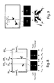
- two exemplary input devices are shown in Figures 1 A and 1 B .
- the device illustrated in Figure 1 A is a remote controller that features two separate clickable touchpads.
- the device illustrated in Figure 1 B is a remote controller that features a single multi-touch surface that can simultaneously discriminate among multiple touch inputs. It will be appreciated that these are simply two possible exemplary embodiments; other embodiments using other types of control sensors are possible.
- a dual pointer device may be implemented using multiple joysticks, trackballs, proximity sensors or the like.
- Pointer management methods rely on the type of mapping that exists between the pointing device space of (e.g. touchpad surface) and the target area of the screen.
- This disclosure will focus initially on absolute pointing methods but the basic concept introduced here can be pertinent to relative pointing as well.
- the innovation employs a dynamic approach to dual pointer or multi-pointer management, in contrast to conventional approaches (overlay method, basic split method), which each use a static strategy.
- any input device(s) providing two or more separate addressing spaces can be implemented, for example, using two or more separate sensors (e.g. two touchpads of Fig. 1 A) or using a single sensor with two or more separate areas (one multi-touch touchpad of Fig. 1 B) with two logical areas.
- two or more separate sensors e.g. two touchpads of Fig. 1 A
- a single sensor with two or more separate areas one multi-touch touchpad of Fig. 1 B
- the exemplary remote controller features two clickable touchpads 20, 22 and a set of application-definable buttons 24. Device orientations (landscape, portrait) and hand positions are automatically detected via capacitive and accelerometer sensors.
- the exemplary remote controller features a single, multi-touch touchpad 26. If desired, certain designated regions on the touchpad 26 can be assigned to a set of application-definable buttons that, when tapped, function in the same manner as the buttons 24 of the Fig. 1 A embodiment.
- the overlay method uses a 1-to-1 mapping between a target screen area 30 and any of the two touchpad areas 20, 22.
- the user can point to any location in the screen area by using indifferently the right or left pointer.
- the right and left pointers are graphically depicted as partial images of the right and left human thumbs: right pointer 32 and left pointer 34.
- the major drawback of the overlay method is that the left and right pointers can easily cross each other, which may leave the user somewhat confused at times. Another issue is the unfavorable overall designation resolution because each touchpad covers the same screen area. In the horizontal space, two touchpad widths (i.e. for left and right touchpad) are used to map into two screen widths.
- the basic split method typically creates a 1-to-1 mapping between each touchpad and a sub-portion of the target screen area.
- the right hand side pointer 32 controlled by the right hand is confined to the right hand side sub-portion 30R of the screen area; respectively the left hand side pointer 34 controlled by the left hand is confined to the left hand side sub-portion 30L of the screen area.
- the left and right pointer will not cross each other, although both pointers can coexist in the middle 30M without crossing.
- the split pointer method improves the designation resolution because two touchpads widths are mapped to one target screen area widths.
- the basic split method has therefore clear advantages over the overlay method.
- experiments have shown that users experience some uneasiness at times due to a perceived proximity conflict illustrated in Figure 4 .
- the present innovation uses a novel dynamic split approach to answer the needs mentioned above and which are:
- the screen addressing area for the left and right pointers is not statically defined, but is rather adjusted dynamically based on the actual positions of those pointers.
- the addressing space R for the right hand side pointer is bound on the left side by the left hand side pointer x-axis position.
- the addressing space L for left hand side pointer is bound on the right side by the right hand side pointer x-axis position.
- the basic dynamic pointer management method illustrated in Figure 6 continuously re-estimates the dynamic boundary so that the right and left pointers do not cross over into the other pointer's region.
- the mild pointer crossing method illustrated in Figure 7 generally enforces the dynamic approach of the absolute pointer management method, but permits a mild overlap of each pointer into the other pointer's region.
- the pointer management method illustrated in Figure 8 enforces the basic dynamic approach, with the added feature of imposing outer limit restrictions to improve further the effective pointer resolution.
- the absolute pointer management case is considered first, followed by a discussion of the relative pointer management case.
- the dynamic boundary subdivides the common display space into a left region and a right region, where the dynamic boundary defines a right edge of the left region and a left edge of the right region.
- the dynamic boundary may be represented as a generally vertical, one-dimensional line, such that the left and right edges are coincident with one another (i.e., the left and right regions abut on another).
- the dynamic boundary represents a boundary region of two dimensions (e.g., such as a rectangular region) that separates the left and right regions. In this mild overlap case, the left and right edges are spaced apart from one another, with the dynamic boundary region lying between.
- the novel remapping method defines a set of desired properties and constraints to provide continuity and motion smoothness.
- the set below represents the core constraints:
- the preferred embodiment of this invention is defined by the following transformations for the left pointer and right pointer when using the normalized space:
- Left_Remap TLx t 0.5 * TLx t + 0.5 * TRx t * TLx t
- Right_Remap TRx t 0.5 * TLx t + 1.0 * TRx t - 0.5 * TRx t * TLx t which can be expressed as the following matricial product:
- SL X t SR X t Clip 0.5 0 0.5 0 0.5 0 0 - 0.5 ⁇ TL X t TR X t TL X t * TR X t 1
- relative mode the same non-crossing pointer constraints (i.e. dynamic boundary management) are preserved but touchpad finger motion is interpreted as an offset with respect to the current screen pointer position.
- Figure 9 shows the effect of a same swipe motion on the left and right touchpad which results in different offsets in the screen space.
- the displacement offset in the screen space illustrated is twice as important for the right pointer as for the left pointer for the same swipe motion on the respective touchpad since the width of right interactive area is twice as wide as the left interactive area.
- touchpad A and touchpad B correspond to the clickable touchpads 20, 22 of Figure 1A .
- These may be implemented as capacitive touch surfaces that are each mounted in a detent structure that allows the respective touch surface to be clicked by a pushing force applied normal to the touchpad surface.
- Such clicking motion activates a micro-switch mounted beneath the touch pad.
- the micro-switch provides a momentary binary signal each time the pad is clicked.
- the multi-touch surface is able to individually detect and discriminate between contact from the right and left hands and thus provides a separate (x,y) position data point for each finger in contact with the touchpad surface.
- User selection of a desired (x,y) position may be effected by sensing a momentary tap by the user's finger, for example.
- the touchpads A and B each provide a first output signal indicative of the (x,y) position where finger contact is made and a second output signal that carries the micro-switch click data. These outputs are fed to the dual port touchpad interface 50, which provides a digital interface to receive each of the output signals from each of the touchpads.
- the interface 50 associates identification or address data to the received signals, to distinguish signals of touchpad A (i.e., left hand touchpad 20 of Fig. 1A ) from signals of touchpad B (i.e., right hand touchpad 22 of Fig. 1A ).
- the address-associated data are fed from interface 50 to a serial input of the processor (CPU) 52.
- Processor (CPU) 52 may be implemented as a microcontroller, microprocessor, or the like. Coupled to the processor 52 is a first memory (e.g., EEPROM memory) 54 that stores the operating instructions that control how the processor functions. A flowchart diagram illustrating these instructions is shown in Figure 11 . To provide working memory to perform the matrix transformations described above, a suitable second memory (e.g., RAM memory) 56 is provided. In Figure 10 , the transformation matrix has been diagrammatically illustrated at 57.
- the button array 58 represents the set of application-definable buttons (buttons 24 of Fig. 1A ).
- the button array may be implemented using suitable micro-switches, membrane switches or the like.
- the button array may be coupled to the processor 52 via the serial interface, as shown, or the individual buttons of the array may each be coupled via dedicated digital inputs of the processor (not shown).
- the remote control device of Figure 10 includes a wireless transmitter 60 which communicates with a corresponding wireless receiver 62.
- Wireless communication can be effected using radio frequency (RF) signals, infrared (IR) signals, or both.
- the processor computes the respective positions for each of the pointers, using the mapping integrator functionality to compute the positions so that a dynamic boundary between the pointer is adjusted based on knowledge of the respective (x,y) positions of the touchpad output signals.
- the processor transmits these pointer position data via the transmitter 60 and receiver 62 to the graphics generator circuitry 64.
- the graphics generator circuitry is designed to generate graphical images of the respective pointers for display within the display space or display region 66 of a display device 68.
- the graphics generator thus supplies the bit-mapped or vector graphics data to render the image of the pointer.
- the point on the screen at which that image is rendered is based on information received wirelessly from the remote control device.
- a hardwired connection may be used between the processor 52 and the graphics generator 64. In such embodiment, the wireless transmitter and wireless receiver would not be used.
- controller circuitry described above can be implemented using an application specific integrated circuit (ASIC), if desired.
- ASIC application specific integrated circuit
- mapping integrator functionality is provided by the processor within the remote control device.
- the mapping integrator functionality can alternatively be placed in the controlled, consumer electronic device (e.g., set top box, television, computer system).
- the position signals are transmitted to the controlled device and an on-board processor or ASIC associated with the controlled device performs the mapping integrator functionality.
- Figure 11 provides a flow diagram illustrating how the processor 52 is programmed and how the graphics generator 64 handles the instructions received from the processor.
- the processor receives input from the input devices (in this case, touchpads A and B). These input values give touchpad coordinates (x,y) and have corresponding addresses denoting which touchpad supplied the data.
- step 102 the processor processes these input data by constructing a transformation matrix 57 in RAM based on the transformation matrix model being used.
- a transformation matrix 57 in RAM based on the transformation matrix model being used.
- the written description above has explained in detail various different transformation matrices that may be used based on the desired behavior of the system (absolute-relative; basic, mild pointer crossing enabled, with/without outer limit constraints). It will be understood that the processor computes the pointer positions by performing matrix multiplication of the input data, based on the matrix used.
- step 104 the processor computes the pointer positions of the respective pointer positions based on the transformed inputs that were processed by the transformation matrix. These pointer positions are then mapped into the display space of the display screen using the common coordinate system of the display space.
- step 106 the pointer positions are then transmitted to the graphics generator.
- the graphics generator 64 then performs the following steps:
- step 108 graphical images are generated for each pointer to be displayed.
- these graphical images can be generated using bitmapped graphics, where the pointer images are pre-stored in memory, or by using vector graphic techniques to generate the images on the fly. In either case, the images are placed on the display screen at locations within the common display space of the screen based on the locations specified in step 104, as depicted at step 110.
- the dual pointer (or multi-pointer) management approach uses data from both (all) input devices to compute the respective positions of both (all) of the pointers.
- the input data are cross-coupled via the transformation matrix, so that the computed pointer positions are interdependent.
- the system generates a dynamic boundary within the common display coordinate system, where the dynamic boundary is adjusted by the processor based on knowledge of the respective position signals from the input devices.
- FIG. 12 presents a functional block diagram of a pointer control apparatus in accordance with the disclosed innovations.
- the input devices device #1 and device #2
- their associated controllers each supply a position signal, on signal lines 200 and 202, respectively.
- These are fed to the mapping integrator that generates pointer position data for the left pointer and right pointer on data lines 206 and 208, respectively.
- These pointer position data are then used by the left pointer controller 210 and right pointer controller 212 to generate the respective left and right pointers for display within the display space 66.
- the mapping integrator computes the position of the first pointer within the display coordinate system based in part upon the position signal of the first input device and based in part upon the position signal of the second input device, and computes the position of the second pointer within the display coordinate system based in part upon the position signal of the second input device and based in part upon the position signal of the first input device.
- FIG. 13 shows a multi-device system.
- three input devices are illustrated, but it will be understood that the multi-device system can have any plural number of input devices (i.e, 2 or more input devices).
- a single multi-position input system is employed. This system receives input position signals from each of the input devices 222 and supplies data representing these input signals to the mapping integrator 204.
- the multi-position input system receives each of the input device signals and appends address information to each so that the data take the form of (addr, x, y). These data are then sent in a serial stream to the mapping integrator 204.
- the mapping integrator functions as described above to generate the respective pointer position signals.
- mapping integrator also appends pointer identification tags to each of the pointer positions calculated.
- the output of the mapping integrator thus takes the form of (pointer tag, x, y) where the pointer tag indicates to which pointer the data corresponds (left, right, middle, etc.) and the x,y values represent positions within the common display coordinate system (i.e., within the display space).
- the pointer generation system 205 receives the output data of the mapping integrator, parses the data by pointer tag and then generates and displays the pointer images within the display space.
- the present innovation employs novel dynamic boundary control techniques to solve many problems arising in multi-pointer control applications.
- the innovation enables a more intuitive interaction model for dual pointer-based input which is based on a non-crossing (or mildly crossing) pointer approach and that allows users to use any pointer to reach any area of the display.
- the input devices can be any pointing device that provides at least one degree or more of movement, such as touchpads, touch screens and joysticks.
- the innovation also provides input speed advantages when compared to traditional input methods due its dynamic precision/flexibility tradeoff management.
- Typical applications for dual pointer input are text entry using a virtual keyboard displayed on screen, or multiple object selection tasks, for instance.
- the dual pointer techniques are also well suited to gaming applications as well.
Landscapes
- Engineering & Computer Science (AREA)
- General Engineering & Computer Science (AREA)
- Theoretical Computer Science (AREA)
- Human Computer Interaction (AREA)
- Physics & Mathematics (AREA)
- General Physics & Mathematics (AREA)
- Position Input By Displaying (AREA)
- User Interface Of Digital Computer (AREA)
Applications Claiming Priority (3)
| Application Number | Priority Date | Filing Date | Title |
|---|---|---|---|
| US22072109P | 2009-06-26 | 2009-06-26 | |
| US12/687,930 US8188969B2 (en) | 2009-06-26 | 2010-01-15 | Dual pointer management method using cooperating input sources and efficient dynamic coordinate remapping |
| PCT/US2010/039303 WO2010151501A1 (en) | 2009-06-26 | 2010-06-21 | Dual pointer management method using cooperating input sources and efficient dynamic coordinate remapping |
Publications (3)
| Publication Number | Publication Date |
|---|---|
| EP2446344A1 EP2446344A1 (en) | 2012-05-02 |
| EP2446344A4 EP2446344A4 (en) | 2013-09-11 |
| EP2446344B1 true EP2446344B1 (en) | 2016-03-02 |
Family
ID=43380125
Family Applications (1)
| Application Number | Title | Priority Date | Filing Date |
|---|---|---|---|
| EP10792551.3A Not-in-force EP2446344B1 (en) | 2009-06-26 | 2010-06-21 | Dual pointer management method using cooperating input sources and efficient dynamic coordinate remapping |
Country Status (6)
| Country | Link |
|---|---|
| US (2) | US8188969B2 (enExample) |
| EP (1) | EP2446344B1 (enExample) |
| JP (1) | JP5411989B2 (enExample) |
| CN (1) | CN102449590B (enExample) |
| TW (1) | TWI478010B (enExample) |
| WO (1) | WO2010151501A1 (enExample) |
Families Citing this family (28)
| Publication number | Priority date | Publication date | Assignee | Title |
|---|---|---|---|---|
| US20110216014A1 (en) * | 2010-03-05 | 2011-09-08 | Chih-Meng Wu | Multimedia wireless touch control device |
| US8560583B2 (en) | 2010-04-01 | 2013-10-15 | Sony Computer Entertainment Inc. | Media fingerprinting for social networking |
| US9264785B2 (en) | 2010-04-01 | 2016-02-16 | Sony Computer Entertainment Inc. | Media fingerprinting for content determination and retrieval |
| US9814977B2 (en) | 2010-07-13 | 2017-11-14 | Sony Interactive Entertainment Inc. | Supplemental video content on a mobile device |
| US9832441B2 (en) | 2010-07-13 | 2017-11-28 | Sony Interactive Entertainment Inc. | Supplemental content on a mobile device |
| US8730354B2 (en) | 2010-07-13 | 2014-05-20 | Sony Computer Entertainment Inc | Overlay video content on a mobile device |
| US9159165B2 (en) | 2010-07-13 | 2015-10-13 | Sony Computer Entertainment Inc. | Position-dependent gaming, 3-D controller, and handheld as a remote |
| US9143699B2 (en) | 2010-07-13 | 2015-09-22 | Sony Computer Entertainment Inc. | Overlay non-video content on a mobile device |
| TWI456436B (zh) * | 2011-09-01 | 2014-10-11 | Acer Inc | 觸控板裝置以及其控制方法 |
| US9274642B2 (en) * | 2011-10-20 | 2016-03-01 | Microsoft Technology Licensing, Llc | Acceleration-based interaction for multi-pointer indirect input devices |
| US20130106761A1 (en) * | 2011-10-28 | 2013-05-02 | Atmel Corporation | Touch Sensor with Lookup Table |
| JP5452566B2 (ja) * | 2011-10-31 | 2014-03-26 | 本田技研工業株式会社 | 車両用入力装置 |
| US9367230B2 (en) * | 2011-11-08 | 2016-06-14 | Microsoft Technology Licensing, Llc | Interaction models for indirect interaction devices |
| CN102508604A (zh) * | 2011-11-08 | 2012-06-20 | 中兴通讯股份有限公司 | 一种终端显示界面的控制方法及终端 |
| US20130127738A1 (en) * | 2011-11-23 | 2013-05-23 | Microsoft Corporation | Dynamic scaling of touch sensor |
| FR2986715B1 (fr) * | 2012-02-15 | 2014-10-17 | Archos | Procede et dispositif de controle d'au moins un appareil par au moins un autre appareil, appareil et systeme mettant en œuvre un tel dispositif |
| KR20130130453A (ko) * | 2012-05-22 | 2013-12-02 | 엘지전자 주식회사 | 영상표시장치 및 그 동작 방법 |
| US9851801B1 (en) * | 2012-12-07 | 2017-12-26 | American Megatrends, Inc. | Dual touchpad system |
| WO2014175475A1 (en) * | 2013-04-23 | 2014-10-30 | Lg Electronics Inc. | Image display apparatus and method for operating the same |
| JP5920839B2 (ja) * | 2013-06-12 | 2016-05-18 | Necパーソナルコンピュータ株式会社 | 情報処理装置 |
| US10328344B2 (en) * | 2013-10-11 | 2019-06-25 | Valve Corporation | Game controller systems and methods |
| US10289260B2 (en) | 2014-08-27 | 2019-05-14 | Honda Motor Co., Ltd. | Systems and techniques for application multi-tasking |
| CN106020661B (zh) | 2014-12-31 | 2020-11-24 | 本田技研工业株式会社 | 具有内部边框的跟踪板 |
| KR101647452B1 (ko) * | 2015-05-28 | 2016-08-10 | 동서울대학교 산학협력단 | 터치 스크린 디바이스 기반 복수의 커서 제어 방법 |
| US10402161B2 (en) | 2016-11-13 | 2019-09-03 | Honda Motor Co., Ltd. | Human-vehicle interaction |
| TWI663531B (zh) * | 2017-08-18 | 2019-06-21 | 友達光電股份有限公司 | 具有觸控面板之電子裝置及其控制電路 |
| CN108052346B (zh) * | 2017-10-23 | 2020-03-27 | 天芯智能(深圳)股份有限公司 | 一种控制智能手表的方法、系统及智能手表 |
| US20240192794A1 (en) * | 2022-12-09 | 2024-06-13 | Dell Products L.P. | Adjustable input modes for a handheld controller |
Family Cites Families (13)
| Publication number | Priority date | Publication date | Assignee | Title |
|---|---|---|---|---|
| JPH07105191A (ja) * | 1993-09-30 | 1995-04-21 | Fujitsu Ltd | 共有文書表示システム |
| US5586243A (en) * | 1994-04-15 | 1996-12-17 | International Business Machines Corporation | Multiple display pointers for computer graphical user interfaces |
| US6204837B1 (en) * | 1998-07-13 | 2001-03-20 | Hewlett-Packard Company | Computing apparatus having multiple pointing devices |
| US20040263484A1 (en) * | 2003-06-25 | 2004-12-30 | Tapio Mantysalo | Multifunctional UI input device for moblie terminals |
| US20050176505A1 (en) * | 2004-02-09 | 2005-08-11 | Stanley Mark J. | Method and apparatus for providing computer pointing device input to a video game console |
| US7620915B2 (en) * | 2004-02-13 | 2009-11-17 | Ludwig Lester F | Electronic document editing employing multiple cursors |
| US20060090022A1 (en) * | 2004-10-22 | 2006-04-27 | Intergraph Hardware Technologies Company | Input device for controlling movement in a three-dimensional virtual environment |
| US20060143571A1 (en) * | 2004-12-29 | 2006-06-29 | Wilson Chan | Multiple mouse cursors for use within a viewable area for a computer |
| TW200807284A (en) * | 2006-07-17 | 2008-02-01 | Guan-Lin Chen | Programmable touch system |
| US7768514B2 (en) * | 2006-12-19 | 2010-08-03 | International Business Machines Corporation | Simultaneous view and point navigation |
| JP2010521022A (ja) * | 2007-02-23 | 2010-06-17 | ティーピーアイ カンパニー リミテッド | デジタル機器に使われるポインティング装置を利用した仮想キーボード入力システム |
| WO2008152679A1 (ja) * | 2007-06-13 | 2008-12-18 | Yappa Corporation | 携帯端末装置および入力装置 |
| US20090184936A1 (en) * | 2008-01-22 | 2009-07-23 | Mathematical Inventing - Slicon Valley | 3D touchpad |
-
2010
- 2010-01-15 US US12/687,930 patent/US8188969B2/en not_active Expired - Fee Related
- 2010-04-22 TW TW099112662A patent/TWI478010B/zh not_active IP Right Cessation
- 2010-06-21 WO PCT/US2010/039303 patent/WO2010151501A1/en not_active Ceased
- 2010-06-21 US US13/375,337 patent/US8451219B2/en not_active Expired - Fee Related
- 2010-06-21 JP JP2012517619A patent/JP5411989B2/ja not_active Expired - Fee Related
- 2010-06-21 EP EP10792551.3A patent/EP2446344B1/en not_active Not-in-force
- 2010-06-21 CN CN201080023504.5A patent/CN102449590B/zh not_active Expired - Fee Related
Also Published As
| Publication number | Publication date |
|---|---|
| US20120113005A1 (en) | 2012-05-10 |
| TWI478010B (zh) | 2015-03-21 |
| CN102449590A (zh) | 2012-05-09 |
| CN102449590B (zh) | 2014-01-08 |
| WO2010151501A1 (en) | 2010-12-29 |
| EP2446344A1 (en) | 2012-05-02 |
| JP5411989B2 (ja) | 2014-02-12 |
| US8188969B2 (en) | 2012-05-29 |
| US8451219B2 (en) | 2013-05-28 |
| TW201101121A (en) | 2011-01-01 |
| US20100328206A1 (en) | 2010-12-30 |
| JP2012531667A (ja) | 2012-12-10 |
| EP2446344A4 (en) | 2013-09-11 |
Similar Documents
| Publication | Publication Date | Title |
|---|---|---|
| EP2446344B1 (en) | Dual pointer management method using cooperating input sources and efficient dynamic coordinate remapping | |
| US11221730B2 (en) | Input device for VR/AR applications | |
| US8614664B2 (en) | Multi-touch multi-dimensional mouse | |
| JP5237847B2 (ja) | ジェスチャ認識方法及びそれを組み込んだタッチシステム | |
| US5748185A (en) | Touchpad with scroll and pan regions | |
| US8259080B2 (en) | Information handling system display device and methods thereof | |
| US20040104942A1 (en) | Display and operating device, in particular a touch panel | |
| US9223422B2 (en) | Remote controller and display apparatus, control method thereof | |
| US20110205169A1 (en) | Multi-touch input apparatus and its interface method using hybrid resolution based touch data | |
| JP2011028524A (ja) | 情報処理装置、プログラムおよびポインティング方法 | |
| US20110227947A1 (en) | Multi-Touch User Interface Interaction | |
| WO2012077273A1 (ja) | 電子機器 | |
| JP2006500676A (ja) | グラフィカル・ユーザ・インタフェース・ナビゲーション方法、及び装置。 | |
| TW201218036A (en) | Method for combining at least two touch signals in a computer system | |
| JP5275429B2 (ja) | 情報処理装置、プログラムおよびポインティング方法 | |
| JP2011081447A (ja) | 情報処理方法及び情報処理装置 | |
| Benko et al. | Imprecision, inaccuracy, and frustration: The tale of touch input | |
| TWI436262B (zh) | 多物件近接暨觸控裝置及手勢偵測方法 | |
| US8327294B2 (en) | Method and system to reduce workload and skills required in usage of mouse or other pointing devices | |
| CN103870131A (zh) | 一种控制电子设备的方法及电子设备 | |
| JP2001516096A (ja) | ユーザ入力の検出および処理システム | |
| JPH07141140A (ja) | マルチウィンドウ型コンピュータシステム | |
| Olwal et al. | Unit-A Modular Framework for Interaction Technique Design, Development and Implementation | |
| Fukuchi | Concurrent Manipulation of Multiple Components on Graphical User Interface | |
| EP0680644A1 (en) | Multi-functionality user-interface downwards compatible with single-functionality application software |
Legal Events
| Date | Code | Title | Description |
|---|---|---|---|
| PUAI | Public reference made under article 153(3) epc to a published international application that has entered the european phase |
Free format text: ORIGINAL CODE: 0009012 |
|
| 17P | Request for examination filed |
Effective date: 20111128 |
|
| AK | Designated contracting states |
Kind code of ref document: A1 Designated state(s): AL AT BE BG CH CY CZ DE DK EE ES FI FR GB GR HR HU IE IS IT LI LT LU LV MC MK MT NL NO PL PT RO SE SI SK SM TR |
|
| DAX | Request for extension of the european patent (deleted) | ||
| A4 | Supplementary search report drawn up and despatched |
Effective date: 20130808 |
|
| RIC1 | Information provided on ipc code assigned before grant |
Ipc: G06F 3/048 20130101AFI20130802BHEP |
|
| RIC1 | Information provided on ipc code assigned before grant |
Ipc: G06F 3/048 20130101AFI20130910BHEP |
|
| RAP1 | Party data changed (applicant data changed or rights of an application transferred) |
Owner name: PANASONIC INTELLECTUAL PROPERTY CORPORATION OF AME |
|
| GRAP | Despatch of communication of intention to grant a patent |
Free format text: ORIGINAL CODE: EPIDOSNIGR1 |
|
| INTG | Intention to grant announced |
Effective date: 20151113 |
|
| GRAS | Grant fee paid |
Free format text: ORIGINAL CODE: EPIDOSNIGR3 |
|
| GRAA | (expected) grant |
Free format text: ORIGINAL CODE: 0009210 |
|
| AK | Designated contracting states |
Kind code of ref document: B1 Designated state(s): AL AT BE BG CH CY CZ DE DK EE ES FI FR GB GR HR HU IE IS IT LI LT LU LV MC MK MT NL NO PL PT RO SE SI SK SM TR |
|
| REG | Reference to a national code |
Ref country code: GB Ref legal event code: FG4D |
|
| REG | Reference to a national code |
Ref country code: AT Ref legal event code: REF Ref document number: 778453 Country of ref document: AT Kind code of ref document: T Effective date: 20160315 Ref country code: CH Ref legal event code: EP |
|
| REG | Reference to a national code |
Ref country code: IE Ref legal event code: FG4D |
|
| REG | Reference to a national code |
Ref country code: DE Ref legal event code: R096 Ref document number: 602010030939 Country of ref document: DE |
|
| REG | Reference to a national code |
Ref country code: NL Ref legal event code: MP Effective date: 20160302 |
|
| REG | Reference to a national code |
Ref country code: LT Ref legal event code: MG4D |
|
| REG | Reference to a national code |
Ref country code: AT Ref legal event code: MK05 Ref document number: 778453 Country of ref document: AT Kind code of ref document: T Effective date: 20160302 |
|
| PG25 | Lapsed in a contracting state [announced via postgrant information from national office to epo] |
Ref country code: HR Free format text: LAPSE BECAUSE OF FAILURE TO SUBMIT A TRANSLATION OF THE DESCRIPTION OR TO PAY THE FEE WITHIN THE PRESCRIBED TIME-LIMIT Effective date: 20160302 Ref country code: ES Free format text: LAPSE BECAUSE OF FAILURE TO SUBMIT A TRANSLATION OF THE DESCRIPTION OR TO PAY THE FEE WITHIN THE PRESCRIBED TIME-LIMIT Effective date: 20160302 Ref country code: NO Free format text: LAPSE BECAUSE OF FAILURE TO SUBMIT A TRANSLATION OF THE DESCRIPTION OR TO PAY THE FEE WITHIN THE PRESCRIBED TIME-LIMIT Effective date: 20160602 Ref country code: FI Free format text: LAPSE BECAUSE OF FAILURE TO SUBMIT A TRANSLATION OF THE DESCRIPTION OR TO PAY THE FEE WITHIN THE PRESCRIBED TIME-LIMIT Effective date: 20160302 Ref country code: GR Free format text: LAPSE BECAUSE OF FAILURE TO SUBMIT A TRANSLATION OF THE DESCRIPTION OR TO PAY THE FEE WITHIN THE PRESCRIBED TIME-LIMIT Effective date: 20160603 |
|
| PG25 | Lapsed in a contracting state [announced via postgrant information from national office to epo] |
Ref country code: SE Free format text: LAPSE BECAUSE OF FAILURE TO SUBMIT A TRANSLATION OF THE DESCRIPTION OR TO PAY THE FEE WITHIN THE PRESCRIBED TIME-LIMIT Effective date: 20160302 Ref country code: LT Free format text: LAPSE BECAUSE OF FAILURE TO SUBMIT A TRANSLATION OF THE DESCRIPTION OR TO PAY THE FEE WITHIN THE PRESCRIBED TIME-LIMIT Effective date: 20160302 Ref country code: PL Free format text: LAPSE BECAUSE OF FAILURE TO SUBMIT A TRANSLATION OF THE DESCRIPTION OR TO PAY THE FEE WITHIN THE PRESCRIBED TIME-LIMIT Effective date: 20160302 Ref country code: NL Free format text: LAPSE BECAUSE OF FAILURE TO SUBMIT A TRANSLATION OF THE DESCRIPTION OR TO PAY THE FEE WITHIN THE PRESCRIBED TIME-LIMIT Effective date: 20160302 Ref country code: AT Free format text: LAPSE BECAUSE OF FAILURE TO SUBMIT A TRANSLATION OF THE DESCRIPTION OR TO PAY THE FEE WITHIN THE PRESCRIBED TIME-LIMIT Effective date: 20160302 Ref country code: LV Free format text: LAPSE BECAUSE OF FAILURE TO SUBMIT A TRANSLATION OF THE DESCRIPTION OR TO PAY THE FEE WITHIN THE PRESCRIBED TIME-LIMIT Effective date: 20160302 |
|
| PG25 | Lapsed in a contracting state [announced via postgrant information from national office to epo] |
Ref country code: IS Free format text: LAPSE BECAUSE OF FAILURE TO SUBMIT A TRANSLATION OF THE DESCRIPTION OR TO PAY THE FEE WITHIN THE PRESCRIBED TIME-LIMIT Effective date: 20160702 Ref country code: EE Free format text: LAPSE BECAUSE OF FAILURE TO SUBMIT A TRANSLATION OF THE DESCRIPTION OR TO PAY THE FEE WITHIN THE PRESCRIBED TIME-LIMIT Effective date: 20160302 |
|
| PG25 | Lapsed in a contracting state [announced via postgrant information from national office to epo] |
Ref country code: SK Free format text: LAPSE BECAUSE OF FAILURE TO SUBMIT A TRANSLATION OF THE DESCRIPTION OR TO PAY THE FEE WITHIN THE PRESCRIBED TIME-LIMIT Effective date: 20160302 Ref country code: RO Free format text: LAPSE BECAUSE OF FAILURE TO SUBMIT A TRANSLATION OF THE DESCRIPTION OR TO PAY THE FEE WITHIN THE PRESCRIBED TIME-LIMIT Effective date: 20160302 Ref country code: CZ Free format text: LAPSE BECAUSE OF FAILURE TO SUBMIT A TRANSLATION OF THE DESCRIPTION OR TO PAY THE FEE WITHIN THE PRESCRIBED TIME-LIMIT Effective date: 20160302 Ref country code: SM Free format text: LAPSE BECAUSE OF FAILURE TO SUBMIT A TRANSLATION OF THE DESCRIPTION OR TO PAY THE FEE WITHIN THE PRESCRIBED TIME-LIMIT Effective date: 20160302 Ref country code: PT Free format text: LAPSE BECAUSE OF FAILURE TO SUBMIT A TRANSLATION OF THE DESCRIPTION OR TO PAY THE FEE WITHIN THE PRESCRIBED TIME-LIMIT Effective date: 20160704 |
|
| REG | Reference to a national code |
Ref country code: DE Ref legal event code: R097 Ref document number: 602010030939 Country of ref document: DE |
|
| PG25 | Lapsed in a contracting state [announced via postgrant information from national office to epo] |
Ref country code: IT Free format text: LAPSE BECAUSE OF FAILURE TO SUBMIT A TRANSLATION OF THE DESCRIPTION OR TO PAY THE FEE WITHIN THE PRESCRIBED TIME-LIMIT Effective date: 20160302 Ref country code: BE Free format text: LAPSE BECAUSE OF FAILURE TO SUBMIT A TRANSLATION OF THE DESCRIPTION OR TO PAY THE FEE WITHIN THE PRESCRIBED TIME-LIMIT Effective date: 20160302 |
|
| PLBE | No opposition filed within time limit |
Free format text: ORIGINAL CODE: 0009261 |
|
| STAA | Information on the status of an ep patent application or granted ep patent |
Free format text: STATUS: NO OPPOSITION FILED WITHIN TIME LIMIT |
|
| PG25 | Lapsed in a contracting state [announced via postgrant information from national office to epo] |
Ref country code: MC Free format text: LAPSE BECAUSE OF FAILURE TO SUBMIT A TRANSLATION OF THE DESCRIPTION OR TO PAY THE FEE WITHIN THE PRESCRIBED TIME-LIMIT Effective date: 20160302 Ref country code: DK Free format text: LAPSE BECAUSE OF FAILURE TO SUBMIT A TRANSLATION OF THE DESCRIPTION OR TO PAY THE FEE WITHIN THE PRESCRIBED TIME-LIMIT Effective date: 20160302 |
|
| REG | Reference to a national code |
Ref country code: CH Ref legal event code: PL |
|
| 26N | No opposition filed |
Effective date: 20161205 |
|
| PG25 | Lapsed in a contracting state [announced via postgrant information from national office to epo] |
Ref country code: BG Free format text: LAPSE BECAUSE OF FAILURE TO SUBMIT A TRANSLATION OF THE DESCRIPTION OR TO PAY THE FEE WITHIN THE PRESCRIBED TIME-LIMIT Effective date: 20160602 Ref country code: SI Free format text: LAPSE BECAUSE OF FAILURE TO SUBMIT A TRANSLATION OF THE DESCRIPTION OR TO PAY THE FEE WITHIN THE PRESCRIBED TIME-LIMIT Effective date: 20160302 |
|
| GBPC | Gb: european patent ceased through non-payment of renewal fee |
Effective date: 20160621 |
|
| REG | Reference to a national code |
Ref country code: IE Ref legal event code: MM4A |
|
| REG | Reference to a national code |
Ref country code: FR Ref legal event code: ST Effective date: 20170228 |
|
| PG25 | Lapsed in a contracting state [announced via postgrant information from national office to epo] |
Ref country code: CH Free format text: LAPSE BECAUSE OF NON-PAYMENT OF DUE FEES Effective date: 20160630 Ref country code: LI Free format text: LAPSE BECAUSE OF NON-PAYMENT OF DUE FEES Effective date: 20160630 Ref country code: FR Free format text: LAPSE BECAUSE OF NON-PAYMENT OF DUE FEES Effective date: 20160630 |
|
| PG25 | Lapsed in a contracting state [announced via postgrant information from national office to epo] |
Ref country code: GB Free format text: LAPSE BECAUSE OF NON-PAYMENT OF DUE FEES Effective date: 20160621 Ref country code: IE Free format text: LAPSE BECAUSE OF NON-PAYMENT OF DUE FEES Effective date: 20160621 |
|
| PG25 | Lapsed in a contracting state [announced via postgrant information from national office to epo] |
Ref country code: CY Free format text: LAPSE BECAUSE OF FAILURE TO SUBMIT A TRANSLATION OF THE DESCRIPTION OR TO PAY THE FEE WITHIN THE PRESCRIBED TIME-LIMIT Effective date: 20160302 Ref country code: HU Free format text: LAPSE BECAUSE OF FAILURE TO SUBMIT A TRANSLATION OF THE DESCRIPTION OR TO PAY THE FEE WITHIN THE PRESCRIBED TIME-LIMIT; INVALID AB INITIO Effective date: 20100621 |
|
| PG25 | Lapsed in a contracting state [announced via postgrant information from national office to epo] |
Ref country code: MT Free format text: LAPSE BECAUSE OF NON-PAYMENT OF DUE FEES Effective date: 20160630 Ref country code: LU Free format text: LAPSE BECAUSE OF NON-PAYMENT OF DUE FEES Effective date: 20160621 Ref country code: TR Free format text: LAPSE BECAUSE OF FAILURE TO SUBMIT A TRANSLATION OF THE DESCRIPTION OR TO PAY THE FEE WITHIN THE PRESCRIBED TIME-LIMIT Effective date: 20160302 Ref country code: MK Free format text: LAPSE BECAUSE OF FAILURE TO SUBMIT A TRANSLATION OF THE DESCRIPTION OR TO PAY THE FEE WITHIN THE PRESCRIBED TIME-LIMIT Effective date: 20160302 |
|
| PGFP | Annual fee paid to national office [announced via postgrant information from national office to epo] |
Ref country code: DE Payment date: 20180625 Year of fee payment: 9 |
|
| PG25 | Lapsed in a contracting state [announced via postgrant information from national office to epo] |
Ref country code: AL Free format text: LAPSE BECAUSE OF FAILURE TO SUBMIT A TRANSLATION OF THE DESCRIPTION OR TO PAY THE FEE WITHIN THE PRESCRIBED TIME-LIMIT Effective date: 20160302 |
|
| REG | Reference to a national code |
Ref country code: DE Ref legal event code: R119 Ref document number: 602010030939 Country of ref document: DE |
|
| PG25 | Lapsed in a contracting state [announced via postgrant information from national office to epo] |
Ref country code: DE Free format text: LAPSE BECAUSE OF NON-PAYMENT OF DUE FEES Effective date: 20200101 |