EP2446210B1 - Heat-exchanger configuration - Google Patents
Heat-exchanger configuration Download PDFInfo
- Publication number
- EP2446210B1 EP2446210B1 EP10791123.2A EP10791123A EP2446210B1 EP 2446210 B1 EP2446210 B1 EP 2446210B1 EP 10791123 A EP10791123 A EP 10791123A EP 2446210 B1 EP2446210 B1 EP 2446210B1
- Authority
- EP
- European Patent Office
- Prior art keywords
- gap
- plate
- fluid
- heat exchanger
- vanes
- Prior art date
- Legal status (The legal status is an assumption and is not a legal conclusion. Google has not performed a legal analysis and makes no representation as to the accuracy of the status listed.)
- Not-in-force
Links
- 239000012530 fluid Substances 0.000 claims description 65
- 230000002093 peripheral effect Effects 0.000 claims description 18
- 239000007787 solid Substances 0.000 description 4
- 239000000463 material Substances 0.000 description 3
- VVQNEPGJFQJSBK-UHFFFAOYSA-N Methyl methacrylate Chemical compound COC(=O)C(C)=C VVQNEPGJFQJSBK-UHFFFAOYSA-N 0.000 description 1
- 229920005372 Plexiglas® Polymers 0.000 description 1
- 229910052782 aluminium Inorganic materials 0.000 description 1
- XAGFODPZIPBFFR-UHFFFAOYSA-N aluminium Chemical compound [Al] XAGFODPZIPBFFR-UHFFFAOYSA-N 0.000 description 1
- 238000000576 coating method Methods 0.000 description 1
- 238000010438 heat treatment Methods 0.000 description 1
- 238000002347 injection Methods 0.000 description 1
- 239000007924 injection Substances 0.000 description 1
- 239000007788 liquid Substances 0.000 description 1
- 238000012423 maintenance Methods 0.000 description 1
- 229910052751 metal Inorganic materials 0.000 description 1
- 239000002184 metal Substances 0.000 description 1
- 239000000725 suspension Substances 0.000 description 1
- 238000011144 upstream manufacturing Methods 0.000 description 1
Images


Classifications
-
- F—MECHANICAL ENGINEERING; LIGHTING; HEATING; WEAPONS; BLASTING
- F28—HEAT EXCHANGE IN GENERAL
- F28F—DETAILS OF HEAT-EXCHANGE AND HEAT-TRANSFER APPARATUS, OF GENERAL APPLICATION
- F28F13/00—Arrangements for modifying heat-transfer, e.g. increasing, decreasing
- F28F13/06—Arrangements for modifying heat-transfer, e.g. increasing, decreasing by affecting the pattern of flow of the heat-exchange media
- F28F13/12—Arrangements for modifying heat-transfer, e.g. increasing, decreasing by affecting the pattern of flow of the heat-exchange media by creating turbulence, e.g. by stirring, by increasing the force of circulation
-
- F—MECHANICAL ENGINEERING; LIGHTING; HEATING; WEAPONS; BLASTING
- F28—HEAT EXCHANGE IN GENERAL
- F28D—HEAT-EXCHANGE APPARATUS, NOT PROVIDED FOR IN ANOTHER SUBCLASS, IN WHICH THE HEAT-EXCHANGE MEDIA DO NOT COME INTO DIRECT CONTACT
- F28D9/00—Heat-exchange apparatus having stationary plate-like or laminated conduit assemblies for both heat-exchange media, the media being in contact with different sides of a conduit wall
- F28D9/0012—Heat-exchange apparatus having stationary plate-like or laminated conduit assemblies for both heat-exchange media, the media being in contact with different sides of a conduit wall the apparatus having an annular form
-
- F—MECHANICAL ENGINEERING; LIGHTING; HEATING; WEAPONS; BLASTING
- F28—HEAT EXCHANGE IN GENERAL
- F28D—HEAT-EXCHANGE APPARATUS, NOT PROVIDED FOR IN ANOTHER SUBCLASS, IN WHICH THE HEAT-EXCHANGE MEDIA DO NOT COME INTO DIRECT CONTACT
- F28D9/00—Heat-exchange apparatus having stationary plate-like or laminated conduit assemblies for both heat-exchange media, the media being in contact with different sides of a conduit wall
- F28D9/0093—Multi-circuit heat-exchangers, e.g. integrating different heat exchange sections in the same unit or heat-exchangers for more than two fluids
-
- F—MECHANICAL ENGINEERING; LIGHTING; HEATING; WEAPONS; BLASTING
- F28—HEAT EXCHANGE IN GENERAL
- F28F—DETAILS OF HEAT-EXCHANGE AND HEAT-TRANSFER APPARATUS, OF GENERAL APPLICATION
- F28F9/00—Casings; Header boxes; Auxiliary supports for elements; Auxiliary members within casings
- F28F9/02—Header boxes; End plates
- F28F9/0246—Arrangements for connecting header boxes with flow lines
- F28F9/0251—Massive connectors, e.g. blocks; Plate-like connectors
- F28F9/0253—Massive connectors, e.g. blocks; Plate-like connectors with multiple channels, e.g. with combined inflow and outflow channels
Definitions
- the present application pertains to heat exchangers and, more particularly, to a heat-exchanger design for reducing the pressure drop of fluids across the heat exchanger.
- Heat exchangers are commonly used in order to transfer energy from one fluid to another through a solid surface.
- Typical heat exchangers feature tubes, ducts or paths (hereinafter tubes) in which a first fluid circulates as a result of action from a pump, pressure source or the like.
- a second fluid is in contact with an exterior surface of the tube so as to exchange energy with the first fluid circulating in the tubes.
- the tube may be shaped in a coil, provided with fins or the like, depending on the heat-exchanger configuration (e.g., shell and tube, heat-exchanger coil, radiator, etc.).
- An example is given in document EP 1 600 720 .
- a heat exchanger according to the preamble of claim 1 is known from EP 1 600 720 .
- the first plate is a first disk and the second plate is a second disk having a peripheral outline similar to that of the first disk.
- the heat exchanger further comprises at least a fourth plate spaced apart from the second plate to define a third gap with a major portion of the third gap being free of obstructions, a third peripheral wall on the periphery of the third gap having a curved profile inside the third gap, at least one said inlet and at least one said outlet being in fluid communication with the third gap to cause a swirling flow of a fluid in the third gap, with a third one of said outlet being a third pipe centrally positioned in the fourth plate and having a diameter greater than the first pipe to form an annular passage about the first pipe for fluid to exit the third gap, whereby the first pipe and the third pipe are concentric.
- At least one radial outlet pipe is connected to any one of the pipes of the outlets centrally positioned in the plates, for exit of fluids therethrough.
- vanes extend between surfaces of the spaced apart plates in at least one of the gaps to guide fluids in the swirling flow.
- a first set of the vanes are radially distributed and equidistantly spaced from one another and from a center of a respective one of the gaps.
- the first set of vanes is adjacent to the at least one peripheral wall.
- the heat exchanger further comprises a second set of the vanes, the second set of the vanes being radially distributed and equidistantly spaced from one another and from a center of a respective one of the gaps, the second set being positioned between the first set of the vanes and a center of a respective one of the gaps.
- the at least one set of the vanes comprises at least one annular plate integral with the vanes, the annular plate being coplanar with a respective one of the plates when the sets of vanes are in the respective gap.
- vanes are at an 80 degree angle from a radius of the gap.
- the curved profile of the at least one peripheral wall is substantially circular.
- the at least one inlet is tangentially oriented with respect to the curved profile of the at least one gap.
- the heat exchanger 10 of Fig. 1 is a disk-type heat exchanger in which circulates a fluid or combination of fluids, fluid and solid (i.e., liquid and/or gas, with solids in suspension). Another fluid, combination of fluid/solid or fluids is in contact with an exterior surface of the heat exchanger 10.
- fluids hereinafter.
- the heat exchanger 10 of Fig. 1 is therefore said to have a single stage 11.
- the heat exchanger 10 of Fig. 1 has a pair of disks 12.
- the disks 12 are circular in shape, although other shapes are considered, preferably with rounded or arcuate peripheries.
- the disks 12 are spaced apart, so as to define a gap therebetween, in which the fluid will flow.
- a peripheral wall bounds the gap between the disks 12, and inlets 13 (i.e., one or more) are provided in this peripheral wall or in the disks 12, for the injection of fluid into the gap.
- the peripheral wall 13 has a curved inner profile to define the curved inner periphery of the gap. In an embodiment, the curved inner profile of the peripheral wall 13 is circular.
- the disks may be replaced by plates or walls of different shapes, etc.
- a central outlet 14 projects upwardly from one of the disks 12, although both disks 12 may be provided with a central outlet 14.
- the inlet (s) 13 are provided on the periphery of the heat exchanger 10, and the outlet 14 is centrally positioned, the fluid injected into the gap exits centrally.
- the inlets 13 may be oriented so as to give a generally tangential direction, to cause a swirling pattern of the fluid in the gap. Due to the area reduction, the fluid is accelerated (i.e., accelerating flow or in-sink flow). Accordingly, the fluid in the heat exchanger 10 adopts the swirling pattern and remains between the disks 12 until it exits through the central outlet 14. It is observed that the gap between the disks 12 is generally free of obstructions.
- the residence time of the fluid in the stage 11 may be controlled by adjusting the flow of the fluid in the stage 11, for instance by adjusting the intensity of the pump(s) whether upstream or downstream of the heat exchanger 10.
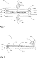
- a configuration similar to that of the heat exchanger 10 of Fig. 1 is illustrated, but with two stages 11. Accordingly, a first fluid circulates in stage 11A, whereas a second fluid circulates in stage 11B.
- stage 11A For clarity purposes, the components of the stage 11A have been affixed with the letter A, whereas the components of stage 11B have been affixed with the letter B. Therefore, in the case of Fig. 2 , two fluids are in heat exchange using the heat-exchanger configuration 10 of Fig. 1 , through common disk 12A/B. One of the fluid absorbs heat released by the other fluid.
- the disk 12A/B is made of a material preferably having high heat conductivity, such as metal (e.g., aluminum).
- the heat exchanger 10 is shown having a multi-disk configuration having five different stages, namely stages 11A, 11B, 11C, 11D and 11E. Accordingly, five different fluids may flow in the separate stages of the heat exchanger 10. Alternatively, some of the stages are combined as different passes for a same fluid, or parallel stages for a same fluid. As an example, a first fluid may circulate in stages 11A, 11C and 11E, while a second fluid circulates in stages 11B and 11C. As another example, the fluid collected at the outlets 14A may be subsequently circulated in stages 11C and 11E, amongst other possibilities. It is observed that stage 11A may have a pair of central outlets 14A, as illustrated. Moreover, the outlets of stages 11B, 11C, 11D and 11E are concentrically positioned with respect to the central outlet 14A, with the outlets 14 of stages 11B-11D forming annular geometries.
- outlets 14B and 14C may comprise outlet pipes projecting radially from the annular central outlets 14B and 14C, although various other configurations may be used as well.
- vanes 15 provided in the gap between disks 12 (i.e., vanes 15A-15C for stages 11A-11C in Fig. 5 ). More specifically, the vanes 15 are provided adjacent to the peripheral wall and thus adjacent to the inlets 13.
- the vanes 15 are narrow rigid plates used to guide the flow of fluid in adopting a swirling pattern in the gap. A leading edge of each vane 15 is closer to the periphery than the trailing edge of the adjacent vane 15. Other devices or deflectors may be used to guide the flow of fluid into the swirling pattern.
- the vanes 15 are radially arranged, and may be equidistantly spaced from a center of the gap and from one another.
- the vanes 15 are provided on a ring plate (i.e., annular plate) coplanar disposed on one of the disks, as shown in Figs. 5 and 6 . Accordingly, all vanes 15 are installed/removed by the simple manipulation of the ring plate (e.g., plexiglass).
- a ring plate i.e., annular plate
- Another similar ring plate with vanes 15 may be provided with a smaller diameter and hence be closer to the center of the heat exchanger 10.
- the vanes are at an 80 degree angle from a radius of the gap between the disks 12. Other materials may be used as well (e.g., mesh).
- vanes 15 Despite the presence of vanes 15, a major portion of the gap is free of obstructions, whereby the fluid adopts a swirling pattern without a spiral-type conduit in the gaps, resulting in relatively low friction.
- the heat exchanger 10 of Figs. 1 to 6 is also relatively simple to maintain, as the disks 12 may readily be separated from one another for maintenance. As is shown in Figs. 4 and 5 , the inlets 13 and peripheral wall may be one integral piece interconnecting the disks 12.
- the applications using the heat exchanger 10 may range from domestic heating systems, to steam power plants, to refineries, amongst numerous possibilities.
Landscapes
- Engineering & Computer Science (AREA)
- Physics & Mathematics (AREA)
- Thermal Sciences (AREA)
- Mechanical Engineering (AREA)
- General Engineering & Computer Science (AREA)
- Heat-Exchange Devices With Radiators And Conduit Assemblies (AREA)
Applications Claiming Priority (2)
| Application Number | Priority Date | Filing Date | Title |
|---|---|---|---|
| US21980109P | 2009-06-24 | 2009-06-24 | |
| PCT/CA2010/000990 WO2010148515A1 (en) | 2009-06-24 | 2010-06-23 | Heat-exchanger configuration |
Publications (3)
| Publication Number | Publication Date |
|---|---|
| EP2446210A1 EP2446210A1 (en) | 2012-05-02 |
| EP2446210A4 EP2446210A4 (en) | 2014-12-31 |
| EP2446210B1 true EP2446210B1 (en) | 2018-05-30 |
Family
ID=43385839
Family Applications (1)
| Application Number | Title | Priority Date | Filing Date |
|---|---|---|---|
| EP10791123.2A Not-in-force EP2446210B1 (en) | 2009-06-24 | 2010-06-23 | Heat-exchanger configuration |
Country Status (5)
| Country | Link |
|---|---|
| US (1) | US9222736B2 (cg-RX-API-DMAC7.html) |
| EP (1) | EP2446210B1 (cg-RX-API-DMAC7.html) |
| CA (1) | CA2766466C (cg-RX-API-DMAC7.html) |
| IN (1) | IN2012DN00274A (cg-RX-API-DMAC7.html) |
| WO (1) | WO2010148515A1 (cg-RX-API-DMAC7.html) |
Families Citing this family (2)
| Publication number | Priority date | Publication date | Assignee | Title |
|---|---|---|---|---|
| CN110410897B (zh) * | 2018-04-29 | 2024-11-15 | 北京世纪天创智业系统集成技术有限公司 | 一种新风换气墙体 |
| US11247177B1 (en) | 2021-09-29 | 2022-02-15 | King Abdulaziz University | Swirling flow generator for membrane distillation |
Citations (3)
| Publication number | Priority date | Publication date | Assignee | Title |
|---|---|---|---|---|
| JPS62155495A (ja) * | 1985-12-27 | 1987-07-10 | Saamobonitsuku:Kk | 熱交換用フイン |
| US20050255420A1 (en) * | 2004-05-15 | 2005-11-17 | Swee Keng Lim | Direct Thermal Transport (DTT) |
| EP1600720A2 (en) * | 2004-05-25 | 2005-11-30 | Worgas Bruciatori S.R.L. | Combustion apparatus |
Family Cites Families (34)
| Publication number | Priority date | Publication date | Assignee | Title |
|---|---|---|---|---|
| US840667A (en) * | 1906-10-13 | 1907-01-08 | John Herbert Wallace | Heat-interchanger. |
| US2677942A (en) * | 1951-03-30 | 1954-05-11 | Separator Ab | Cooling machine for oleaginous substances |
| US3099315A (en) * | 1959-05-27 | 1963-07-30 | Joseph H Loehr | Heat exchanger |
| US3854530A (en) | 1969-12-29 | 1974-12-17 | E Jouet | Heat exchanger |
| US3602298A (en) * | 1969-04-25 | 1971-08-31 | Mecislaus Joseph Ciesielski | Heat exchanger |
| US3788393A (en) * | 1972-05-01 | 1974-01-29 | Us Navy | Heat exchange system |
| US3882934A (en) | 1972-06-02 | 1975-05-13 | Aga Ab | Heat exchanger |
| SE417457B (sv) | 1975-08-28 | 1981-03-16 | Alfa Laval Ab | Spiralvermevexlare |
| US4200734A (en) * | 1977-11-21 | 1980-04-29 | Diamond Shamrock Corporation | Process for polymerization of polyvinyl chloride and VCM monomer removal |
| US4260015A (en) * | 1978-10-05 | 1981-04-07 | Organisation Europeenne De Recherches Spatiales | Surface condenser |
| US4291681A (en) | 1980-02-19 | 1981-09-29 | Berringer Robert T | Flat plate heat exchangers |
| DE3137034A1 (de) * | 1981-09-17 | 1983-03-24 | Siemens AG, 1000 Berlin und 8000 München | Verfahren und vorrichtung zum waermetausch an festen oberflaechen |
| SE467321B (sv) | 1982-02-08 | 1992-06-29 | Elge Ab | Spiralvaermevaexlare daer roeren har aatminstone delvis plana sidoytor |
| FI75664C (fi) | 1985-10-14 | 1990-01-30 | Outokumpu Oy | Dubbelspiralvaermeoeverfoerare. |
| US4997034A (en) | 1987-12-23 | 1991-03-05 | Minnesota Mining And Manufacturing Company | Heat exchanger |
| US4883117A (en) | 1988-07-20 | 1989-11-28 | Sundstrand Corporation | Swirl flow heat exchanger with reverse spiral configuration |
| US5365400A (en) | 1988-09-09 | 1994-11-15 | Hitachi, Ltd. | Heat sinks and semiconductor cooling device using the heat sinks |
| US4993487A (en) | 1989-03-29 | 1991-02-19 | Sundstrand Corporation | Spiral heat exchanger |
| GB8918446D0 (en) | 1989-08-12 | 1989-09-20 | Stokes Keith H | Heat exchange apparatus |
| JPH07310998A (ja) * | 1994-05-17 | 1995-11-28 | Kankyo Kagaku Kogyo Kk | 熱交換器 |
| DE19510847C2 (de) | 1995-03-17 | 2002-11-21 | Michael Rehberg | Plattenwärmetauscher |
| US5787974A (en) | 1995-06-07 | 1998-08-04 | Pennington; Robert L. | Spiral heat exchanger and method of manufacture |
| US5838880A (en) * | 1996-01-16 | 1998-11-17 | Ground Heaters, Inc. | Ground heating system |
| JP3574727B2 (ja) | 1997-03-31 | 2004-10-06 | 国際技術開発株式会社 | 熱交換装置 |
| DE19854204C2 (de) * | 1998-11-24 | 2000-06-15 | Sollich Gmbh & Co Kg | Vorrichtung zum kontinuierlichen Aufbereiten von zu verarbeitenden kakaobutterhaltigen oder ähnlichen fetthaltigen Massen |
| US6152215A (en) | 1998-12-23 | 2000-11-28 | Sundstrand Corporation | High intensity cooler |
| SE9903367D0 (sv) * | 1999-09-20 | 1999-09-20 | Alfa Laval Ab | A spiral heat exchanger |
| HK1052382B (en) | 2000-08-10 | 2008-06-20 | Kankyo Co., Ltd. | Heat exchanger, method of manufacturing the heat exchanger, and dehumidification machine including the heat exchanger |
| US6796370B1 (en) * | 2000-11-03 | 2004-09-28 | Cray Inc. | Semiconductor circular and radial flow cooler |
| EP1431694B1 (en) * | 2001-09-25 | 2014-09-10 | Honda Giken Kogyo Kabushiki Kaisha | Heat accumulation unit and method of manufacturing the unit |
| FR2872269B1 (fr) * | 2004-06-29 | 2006-10-20 | Lgl France Sa | Dispositif d'echange de chaleur pour machine de production de froid |
| US7269011B2 (en) * | 2005-08-04 | 2007-09-11 | Delphi Technologies, Inc. | Impingement cooled heat sink with uniformly spaced curved channels |
| SE529808C2 (sv) * | 2006-04-06 | 2007-11-27 | Alfa Laval Corp Ab | Plattvärmeväxlare |
| US7987900B2 (en) * | 2008-04-21 | 2011-08-02 | Mikutay Corporation | Heat exchanger with heat exchange chambers utilizing respective medium directing members |
-
2010
- 2010-06-23 US US13/380,157 patent/US9222736B2/en not_active Expired - Fee Related
- 2010-06-23 WO PCT/CA2010/000990 patent/WO2010148515A1/en not_active Ceased
- 2010-06-23 IN IN274DEN2012 patent/IN2012DN00274A/en unknown
- 2010-06-23 CA CA2766466A patent/CA2766466C/en not_active Expired - Fee Related
- 2010-06-23 EP EP10791123.2A patent/EP2446210B1/en not_active Not-in-force
Patent Citations (3)
| Publication number | Priority date | Publication date | Assignee | Title |
|---|---|---|---|---|
| JPS62155495A (ja) * | 1985-12-27 | 1987-07-10 | Saamobonitsuku:Kk | 熱交換用フイン |
| US20050255420A1 (en) * | 2004-05-15 | 2005-11-17 | Swee Keng Lim | Direct Thermal Transport (DTT) |
| EP1600720A2 (en) * | 2004-05-25 | 2005-11-30 | Worgas Bruciatori S.R.L. | Combustion apparatus |
Also Published As
| Publication number | Publication date |
|---|---|
| US9222736B2 (en) | 2015-12-29 |
| WO2010148515A1 (en) | 2010-12-29 |
| IN2012DN00274A (cg-RX-API-DMAC7.html) | 2015-05-08 |
| EP2446210A1 (en) | 2012-05-02 |
| CA2766466A1 (en) | 2010-12-29 |
| US20120186794A1 (en) | 2012-07-26 |
| CA2766466C (en) | 2016-10-18 |
| EP2446210A4 (en) | 2014-12-31 |
Similar Documents
| Publication | Publication Date | Title |
|---|---|---|
| US10119765B2 (en) | Arc-shaped plate heat exchanger | |
| CN104040256B (zh) | 包括旋流器的分离装置 | |
| RU2717176C1 (ru) | Трубчатый теплообменник | |
| MXPA04003653A (es) | Unidad de intercambio de calor para reactores quimicos isotermicos. | |
| KR20220111248A (ko) | 열교환기 | |
| EP3394522B1 (en) | Fired heat exchanger | |
| CN110088555B (zh) | 进料流出物热交换器 | |
| EP3467420A1 (en) | Arc-shaped plate heat exchanger | |
| EP2446210B1 (en) | Heat-exchanger configuration | |
| CN104285117B (zh) | 具有旁路和混合器的废热锅炉 | |
| CN106767040A (zh) | 柱状环形式水冷换热器 | |
| US12000661B2 (en) | Flow reactor | |
| KR20180060262A (ko) | 판형 열교환기 | |
| WO2020112033A8 (en) | A microchannel heat exchanger | |
| KR102859714B1 (ko) | 열교환기 | |
| WO2015145204A1 (en) | Hydromechanical heat generator | |
| CN111595190B (zh) | 一种强化传热传质管插件及传热传质管道 | |
| KR102163029B1 (ko) | 관체형 열교환기 | |
| KR101572113B1 (ko) | 복수기 | |
| CN110779356B (zh) | 一种高效螺旋管换热器 | |
| SK272019A3 (sk) | Výmenník tepla s koaxiálnymi skrutkovito stočenými rúrami | |
| JP2012200662A (ja) | 流体混合装置および蒸気タービンプラント | |
| SK302019U1 (sk) | Výmenník tepla s koaxiálnymi skrutkovito stočenými rúrami | |
| CZ17671U1 (cs) | Výměník tepla | |
| JP2012207898A (ja) | 多管式熱交換器 |
Legal Events
| Date | Code | Title | Description |
|---|---|---|---|
| PUAI | Public reference made under article 153(3) epc to a published international application that has entered the european phase |
Free format text: ORIGINAL CODE: 0009012 |
|
| 17P | Request for examination filed |
Effective date: 20120123 |
|
| AK | Designated contracting states |
Kind code of ref document: A1 Designated state(s): AL AT BE BG CH CY CZ DE DK EE ES FI FR GB GR HR HU IE IS IT LI LT LU LV MC MK MT NL NO PL PT RO SE SI SK SM TR |
|
| DAX | Request for extension of the european patent (deleted) | ||
| REG | Reference to a national code |
Ref country code: HK Ref legal event code: DE Ref document number: 1169853 Country of ref document: HK |
|
| A4 | Supplementary search report drawn up and despatched |
Effective date: 20141202 |
|
| RIC1 | Information provided on ipc code assigned before grant |
Ipc: F28F 9/02 20060101ALI20141126BHEP Ipc: F28F 3/04 20060101ALI20141126BHEP Ipc: F28F 3/08 20060101ALI20141126BHEP Ipc: F28D 1/03 20060101ALI20141126BHEP Ipc: F28D 9/00 20060101AFI20141126BHEP Ipc: F28F 13/06 20060101ALI20141126BHEP Ipc: F28D 7/10 20060101ALI20141126BHEP |
|
| 17Q | First examination report despatched |
Effective date: 20160419 |
|
| GRAP | Despatch of communication of intention to grant a patent |
Free format text: ORIGINAL CODE: EPIDOSNIGR1 |
|
| INTG | Intention to grant announced |
Effective date: 20171220 |
|
| GRAS | Grant fee paid |
Free format text: ORIGINAL CODE: EPIDOSNIGR3 |
|
| GRAA | (expected) grant |
Free format text: ORIGINAL CODE: 0009210 |
|
| AK | Designated contracting states |
Kind code of ref document: B1 Designated state(s): AL AT BE BG CH CY CZ DE DK EE ES FI FR GB GR HR HU IE IS IT LI LT LU LV MC MK MT NL NO PL PT RO SE SI SK SM TR |
|
| REG | Reference to a national code |
Ref country code: GB Ref legal event code: FG4D |
|
| REG | Reference to a national code |
Ref country code: CH Ref legal event code: EP |
|
| REG | Reference to a national code |
Ref country code: AT Ref legal event code: REF Ref document number: 1004046 Country of ref document: AT Kind code of ref document: T Effective date: 20180615 |
|
| REG | Reference to a national code |
Ref country code: DE Ref legal event code: R096 Ref document number: 602010050992 Country of ref document: DE |
|
| REG | Reference to a national code |
Ref country code: IE Ref legal event code: FG4D |
|
| REG | Reference to a national code |
Ref country code: FR Ref legal event code: PLFP Year of fee payment: 9 |
|
| PGFP | Annual fee paid to national office [announced via postgrant information from national office to epo] |
Ref country code: FR Payment date: 20180629 Year of fee payment: 9 |
|
| REG | Reference to a national code |
Ref country code: NL Ref legal event code: MP Effective date: 20180530 |
|
| REG | Reference to a national code |
Ref country code: LT Ref legal event code: MG4D |
|
| PG25 | Lapsed in a contracting state [announced via postgrant information from national office to epo] |
Ref country code: BG Free format text: LAPSE BECAUSE OF FAILURE TO SUBMIT A TRANSLATION OF THE DESCRIPTION OR TO PAY THE FEE WITHIN THE PRESCRIBED TIME-LIMIT Effective date: 20180830 Ref country code: NO Free format text: LAPSE BECAUSE OF FAILURE TO SUBMIT A TRANSLATION OF THE DESCRIPTION OR TO PAY THE FEE WITHIN THE PRESCRIBED TIME-LIMIT Effective date: 20180830 Ref country code: FI Free format text: LAPSE BECAUSE OF FAILURE TO SUBMIT A TRANSLATION OF THE DESCRIPTION OR TO PAY THE FEE WITHIN THE PRESCRIBED TIME-LIMIT Effective date: 20180530 Ref country code: SE Free format text: LAPSE BECAUSE OF FAILURE TO SUBMIT A TRANSLATION OF THE DESCRIPTION OR TO PAY THE FEE WITHIN THE PRESCRIBED TIME-LIMIT Effective date: 20180530 Ref country code: LT Free format text: LAPSE BECAUSE OF FAILURE TO SUBMIT A TRANSLATION OF THE DESCRIPTION OR TO PAY THE FEE WITHIN THE PRESCRIBED TIME-LIMIT Effective date: 20180530 Ref country code: CY Free format text: LAPSE BECAUSE OF FAILURE TO SUBMIT A TRANSLATION OF THE DESCRIPTION OR TO PAY THE FEE WITHIN THE PRESCRIBED TIME-LIMIT Effective date: 20180530 Ref country code: ES Free format text: LAPSE BECAUSE OF FAILURE TO SUBMIT A TRANSLATION OF THE DESCRIPTION OR TO PAY THE FEE WITHIN THE PRESCRIBED TIME-LIMIT Effective date: 20180530 |
|
| PGFP | Annual fee paid to national office [announced via postgrant information from national office to epo] |
Ref country code: DE Payment date: 20180629 Year of fee payment: 9 |
|
| PG25 | Lapsed in a contracting state [announced via postgrant information from national office to epo] |
Ref country code: HR Free format text: LAPSE BECAUSE OF FAILURE TO SUBMIT A TRANSLATION OF THE DESCRIPTION OR TO PAY THE FEE WITHIN THE PRESCRIBED TIME-LIMIT Effective date: 20180530 Ref country code: LV Free format text: LAPSE BECAUSE OF FAILURE TO SUBMIT A TRANSLATION OF THE DESCRIPTION OR TO PAY THE FEE WITHIN THE PRESCRIBED TIME-LIMIT Effective date: 20180530 Ref country code: GR Free format text: LAPSE BECAUSE OF FAILURE TO SUBMIT A TRANSLATION OF THE DESCRIPTION OR TO PAY THE FEE WITHIN THE PRESCRIBED TIME-LIMIT Effective date: 20180831 |
|
| REG | Reference to a national code |
Ref country code: AT Ref legal event code: MK05 Ref document number: 1004046 Country of ref document: AT Kind code of ref document: T Effective date: 20180530 |
|
| PG25 | Lapsed in a contracting state [announced via postgrant information from national office to epo] |
Ref country code: NL Free format text: LAPSE BECAUSE OF FAILURE TO SUBMIT A TRANSLATION OF THE DESCRIPTION OR TO PAY THE FEE WITHIN THE PRESCRIBED TIME-LIMIT Effective date: 20180530 |
|
| REG | Reference to a national code |
Ref country code: HK Ref legal event code: WD Ref document number: 1169853 Country of ref document: HK |
|
| PG25 | Lapsed in a contracting state [announced via postgrant information from national office to epo] |
Ref country code: SK Free format text: LAPSE BECAUSE OF FAILURE TO SUBMIT A TRANSLATION OF THE DESCRIPTION OR TO PAY THE FEE WITHIN THE PRESCRIBED TIME-LIMIT Effective date: 20180530 Ref country code: RO Free format text: LAPSE BECAUSE OF FAILURE TO SUBMIT A TRANSLATION OF THE DESCRIPTION OR TO PAY THE FEE WITHIN THE PRESCRIBED TIME-LIMIT Effective date: 20180530 Ref country code: CZ Free format text: LAPSE BECAUSE OF FAILURE TO SUBMIT A TRANSLATION OF THE DESCRIPTION OR TO PAY THE FEE WITHIN THE PRESCRIBED TIME-LIMIT Effective date: 20180530 Ref country code: DK Free format text: LAPSE BECAUSE OF FAILURE TO SUBMIT A TRANSLATION OF THE DESCRIPTION OR TO PAY THE FEE WITHIN THE PRESCRIBED TIME-LIMIT Effective date: 20180530 Ref country code: EE Free format text: LAPSE BECAUSE OF FAILURE TO SUBMIT A TRANSLATION OF THE DESCRIPTION OR TO PAY THE FEE WITHIN THE PRESCRIBED TIME-LIMIT Effective date: 20180530 Ref country code: AT Free format text: LAPSE BECAUSE OF FAILURE TO SUBMIT A TRANSLATION OF THE DESCRIPTION OR TO PAY THE FEE WITHIN THE PRESCRIBED TIME-LIMIT Effective date: 20180530 Ref country code: PL Free format text: LAPSE BECAUSE OF FAILURE TO SUBMIT A TRANSLATION OF THE DESCRIPTION OR TO PAY THE FEE WITHIN THE PRESCRIBED TIME-LIMIT Effective date: 20180530 |
|
| REG | Reference to a national code |
Ref country code: CH Ref legal event code: PL |
|
| PG25 | Lapsed in a contracting state [announced via postgrant information from national office to epo] |
Ref country code: SM Free format text: LAPSE BECAUSE OF FAILURE TO SUBMIT A TRANSLATION OF THE DESCRIPTION OR TO PAY THE FEE WITHIN THE PRESCRIBED TIME-LIMIT Effective date: 20180530 Ref country code: IT Free format text: LAPSE BECAUSE OF FAILURE TO SUBMIT A TRANSLATION OF THE DESCRIPTION OR TO PAY THE FEE WITHIN THE PRESCRIBED TIME-LIMIT Effective date: 20180530 |
|
| REG | Reference to a national code |
Ref country code: DE Ref legal event code: R097 Ref document number: 602010050992 Country of ref document: DE |
|
| REG | Reference to a national code |
Ref country code: BE Ref legal event code: MM Effective date: 20180630 |
|
| REG | Reference to a national code |
Ref country code: IE Ref legal event code: MM4A |
|
| PG25 | Lapsed in a contracting state [announced via postgrant information from national office to epo] |
Ref country code: LU Free format text: LAPSE BECAUSE OF NON-PAYMENT OF DUE FEES Effective date: 20180623 Ref country code: MC Free format text: LAPSE BECAUSE OF FAILURE TO SUBMIT A TRANSLATION OF THE DESCRIPTION OR TO PAY THE FEE WITHIN THE PRESCRIBED TIME-LIMIT Effective date: 20180530 |
|
| PLBE | No opposition filed within time limit |
Free format text: ORIGINAL CODE: 0009261 |
|
| STAA | Information on the status of an ep patent application or granted ep patent |
Free format text: STATUS: NO OPPOSITION FILED WITHIN TIME LIMIT |
|
| GBPC | Gb: european patent ceased through non-payment of renewal fee |
Effective date: 20180830 |
|
| PG25 | Lapsed in a contracting state [announced via postgrant information from national office to epo] |
Ref country code: CH Free format text: LAPSE BECAUSE OF NON-PAYMENT OF DUE FEES Effective date: 20180630 Ref country code: IE Free format text: LAPSE BECAUSE OF NON-PAYMENT OF DUE FEES Effective date: 20180623 Ref country code: LI Free format text: LAPSE BECAUSE OF NON-PAYMENT OF DUE FEES Effective date: 20180630 |
|
| 26N | No opposition filed |
Effective date: 20190301 |
|
| PG25 | Lapsed in a contracting state [announced via postgrant information from national office to epo] |
Ref country code: SI Free format text: LAPSE BECAUSE OF FAILURE TO SUBMIT A TRANSLATION OF THE DESCRIPTION OR TO PAY THE FEE WITHIN THE PRESCRIBED TIME-LIMIT Effective date: 20180530 Ref country code: BE Free format text: LAPSE BECAUSE OF NON-PAYMENT OF DUE FEES Effective date: 20180630 |
|
| PG25 | Lapsed in a contracting state [announced via postgrant information from national office to epo] |
Ref country code: GB Free format text: LAPSE BECAUSE OF NON-PAYMENT OF DUE FEES Effective date: 20180830 |
|
| PG25 | Lapsed in a contracting state [announced via postgrant information from national office to epo] |
Ref country code: AL Free format text: LAPSE BECAUSE OF FAILURE TO SUBMIT A TRANSLATION OF THE DESCRIPTION OR TO PAY THE FEE WITHIN THE PRESCRIBED TIME-LIMIT Effective date: 20180530 |
|
| REG | Reference to a national code |
Ref country code: DE Ref legal event code: R119 Ref document number: 602010050992 Country of ref document: DE |
|
| PG25 | Lapsed in a contracting state [announced via postgrant information from national office to epo] |
Ref country code: MT Free format text: LAPSE BECAUSE OF NON-PAYMENT OF DUE FEES Effective date: 20180623 |
|
| PG25 | Lapsed in a contracting state [announced via postgrant information from national office to epo] |
Ref country code: TR Free format text: LAPSE BECAUSE OF FAILURE TO SUBMIT A TRANSLATION OF THE DESCRIPTION OR TO PAY THE FEE WITHIN THE PRESCRIBED TIME-LIMIT Effective date: 20180530 |
|
| PG25 | Lapsed in a contracting state [announced via postgrant information from national office to epo] |
Ref country code: DE Free format text: LAPSE BECAUSE OF NON-PAYMENT OF DUE FEES Effective date: 20200101 |
|
| PG25 | Lapsed in a contracting state [announced via postgrant information from national office to epo] |
Ref country code: HU Free format text: LAPSE BECAUSE OF FAILURE TO SUBMIT A TRANSLATION OF THE DESCRIPTION OR TO PAY THE FEE WITHIN THE PRESCRIBED TIME-LIMIT; INVALID AB INITIO Effective date: 20100623 Ref country code: PT Free format text: LAPSE BECAUSE OF FAILURE TO SUBMIT A TRANSLATION OF THE DESCRIPTION OR TO PAY THE FEE WITHIN THE PRESCRIBED TIME-LIMIT Effective date: 20180530 |
|
| PG25 | Lapsed in a contracting state [announced via postgrant information from national office to epo] |
Ref country code: FR Free format text: LAPSE BECAUSE OF NON-PAYMENT OF DUE FEES Effective date: 20190630 Ref country code: MK Free format text: LAPSE BECAUSE OF NON-PAYMENT OF DUE FEES Effective date: 20180530 |
|
| PG25 | Lapsed in a contracting state [announced via postgrant information from national office to epo] |
Ref country code: IS Free format text: LAPSE BECAUSE OF FAILURE TO SUBMIT A TRANSLATION OF THE DESCRIPTION OR TO PAY THE FEE WITHIN THE PRESCRIBED TIME-LIMIT Effective date: 20180930 |