EP2445683B1 - Befestiungswerkzeug zur befestigung von elementen mit einem kraftstoffinjektor - Google Patents
Befestiungswerkzeug zur befestigung von elementen mit einem kraftstoffinjektor Download PDFInfo
- Publication number
- EP2445683B1 EP2445683B1 EP10732449.3A EP10732449A EP2445683B1 EP 2445683 B1 EP2445683 B1 EP 2445683B1 EP 10732449 A EP10732449 A EP 10732449A EP 2445683 B1 EP2445683 B1 EP 2445683B1
- Authority
- EP
- European Patent Office
- Prior art keywords
- fuel
- tool
- injector
- combustion chamber
- fastening
- Prior art date
- Legal status (The legal status is an assumption and is not a legal conclusion. Google has not performed a legal analysis and makes no representation as to the accuracy of the status listed.)
- Active
Links
Images
Classifications
-
- B—PERFORMING OPERATIONS; TRANSPORTING
- B25—HAND TOOLS; PORTABLE POWER-DRIVEN TOOLS; MANIPULATORS
- B25C—HAND-HELD NAILING OR STAPLING TOOLS; MANUALLY OPERATED PORTABLE STAPLING TOOLS
- B25C1/00—Hand-held nailing tools; Nail feeding devices
- B25C1/08—Hand-held nailing tools; Nail feeding devices operated by combustion pressure
Definitions
- This invention relates to a fastening tool for fastening members, having an internal combustion engine, with a system for controlling the intake of a fuel into a combustion chamber in said tool, said tool further comprising a fuel source, a means for igniting said fuel in said combustion chamber, said system comprising a means including a normally closed valve, with an intake port arranged for communicating with said fuel source, and an exhaust port arranged for communicating with said combustion chamber.
- Patent EP 0,597,241 discloses such a fastening tool according to the preamble of claim 1, wherein the intake control system further comprises an electromagnet able to be energized for opening the valve and a means including an electronic circuit arranged for, under the control of the switch, controlling the electromagnet for opening said valve, in response to said switch being closed, so as to allow said fuel to flow from said source into said combustion chamber.
- the fuel to be used was a liquefied and pressurized gas which, in the cartridge and the valve inlet, is in a liquid phase and, at the outlet of the valve and in the combustion chamber, in a vapour phase.
- the valve With an electromagnet, the valve, a so-called solenoid valve, functions in all or nothing mode, that is either it is closed or opened. Otherwise stated, the solenoid valve delivers the dose of fuel in one shot, which is not necessarily an accuracy guarantee. Such accuracy is all the more difficult to be controlled as the response of the solenoid valve to the control of the switch occurs by means of a transient, adding more inaccuracy to its opening time. It results that operators, in order to be sure that the necessary amount of fuel is available, tend to unnecessarily increase the fuel dose, which makes that the fuel benefit is lost, which is with a same source of fuel, a cartridge, to drive a large number of fastening members.
- this invention relates to a fastening tool for fastening members of the above described type, characterized in that the valve is a fuel injector arranged for pressurizing the fuel at the outlet thereof and thereby micronizing the latter.
- the injector of this invention is a piezoelectric injector, with a stack of piezoelectric quartz discs constituting an electromechanical transducer.
- a fastening tool for fastening members is a direct or indirect fastening tool.
- a direct fastening tool includes a nailing machine, a stapler and an indirect fastening tool includes an anchoring or fixing resin injection gun.
- the fastening tool of this invention works well both with a liquefied and pressurized gas as with a non pressurized liquid such as an alcohol, for example methanol, having the advantage of being able to used as well as a source of energy for a fuel cell.
- a piezoelectric injector is very short, accurate and constant. Dosing the fuel in the combustion chamber could thus be very accurate. As a result of the speed of such an injector, injecting some fuel into the combustion chamber could occur in several operations.
- a piezoelectric injector tool is obviously less polluting.
- the tool of this invention could be small and light.
- an electronic circuit is provided, arranged so as, under the control of a switch, to open the injector for at least a predetermined time interval in order to allow for said fuel to flow from said source into said combustion chamber.
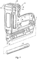
- the fastening tool 10 for internal combustion fastening members comprises a battery 12, an ignition system comprising, amongst other members, a leading switch or interrupter 14 and a triggering switch 16.
- a fuel supply system cooperates with the ignition system so that fuel could flow into a combustion chamber C of the tool 10 during a predetermined time interval after the leading switch 14 has been actuated.
- the fuel supply system cooperates with the ignition system for causing the fuel to flow, into the combustion chamber C, for a predetermined time interval after the triggering switch 16 has been triggered.
- the ignition system is similar to the ignition system described in Patent US no. 5,133,329 .
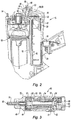
- the leading switch 14 is normally opened and is arranged so as to be closed, as known, by a mobile member 18 of a known type, such as illustrated on Fig. 2 , when a contact member 20 of the sensor, of a known type, is abutting against a support adapted to receive the fastening member.
- the mobile member 18 closes the combustion chamber C, wherein a fan 22 of a known type can be actuated.
- the leading switch 14 is a photoelectric switch.
- the fuel is here a hydrocarbon coming out in a liquid state from a pressurized cartridge 30 of a known type.
- the cartridge 30 has an outlet nosepiece 32, which should be pushed for allowing for the fuel to flow out of the cartridge 30 through the outlet nosepiece 32.
- the tool 10 is arranged for causing the outlet nose piece 32 to be pressed when the cartridge 30 is inserted into the tool 10.
- the tool 10 comprises a shell 40, wherein the cartridge 30 is inserted, and having a cavity 46, the shape of which allows to provide therein a fuel injector 60, that will be described hereinunder.
- the shell 40 comprises a network of passage ducts 42, 44 through which the fuel hydrocarbon flows, getting out of the cartridge 30 through the outlet nosepiece 32.
- the outlet nosepiece 32 opens into the passage duct 42 when the cartridge 30 is inserted into the tool 10.
- the passage duct 44 actually extends the passage duct 42 of the shell 40 in the injector 60.
- the injector 60 comprises a retaining chamber 48, into the passage ducts 44 opens, being an intake port, said chamber 48 ending with a nozzle 50, either plugged or not by a needle 51, as will be now described, the nozzle 50 constituting an exhaust port.
- the nozzle 50 communicates with the combustion chamber C.
- the fuel supply system comprises the fuel injector 60 provided in the cavity 46.
- the fuel injector 60 is arranged so as to inject fuel into the combustion chamber C during a predetermined time interval for thereby controlling the volume of injected fuel.
- the time interval varies with the room temperature and the room pressure.
- the piezoelectric injector 60 illustrated on Fig. 3 in a particular embodiment, thus comprises an inlet duct 44, an outlet nozzle 50, a retaining chamber 48, wherein the duct 44 opens into also communicating with a chamber 52 separating the top of the needle, or punch, of the injector 51 from the top of a plunger 53 arranged in the central well 54 of the stack of piezoelectric discs (quartz) 55 lying on a base 56.
- An annular gasket 57 surrounds the plunger 53.
- Electric wires 58, 59 connected to the battery 12 and to the ground, respectively, allow for a longitudinal electrical potential to be applied to both axial ends of the stack 55. Under a voltage, the stack expands in the longitudinal (axial) dimension.
- a washer 61 with an annular rim 62, is provided on top of the stack 55 and moves with the latter.
- the plunger 53 comprises a head 63 arranged between the rim washer 61 and a second arched spring washer 64 here fixed to the shell 40 of the tool.
- a third washer 65 is arranged between the second arched washer 64 and a fourth Belleville washer 66, the function of which is to bring the punch 51 back to the nozzle 50 in the absence of a voltage across the piezoelectric stack 55.
- the arched spring washer 64 is concave towards the Belleville washer 66.
- it When it is pushed back towards said Belleville washer, by the plunger 53, on its convex face looking at the plunger 53, it meets, at one time, an instability point and the arch thereof is inverted so as to become concave towards the plunger.
- the arched washer 64 is defined to cause the possible move of the central position thereof to be substantially equal or slightly higher than the length along which the punch 51 is to be moved between its plugging position and its opening position of the nozzle 50.
- a control screw 67 for controlling the voltage of the Belleville washer 66.
- the moving length of the punch is bigger than that of the expansion of the piezoelectric stack 55 and of the motion of the plunger 53.
- the fuel is advantageously introduced into the combustion chamber in a time controlled way, rather than in a volume controlled way. Moreover, some components are not necessary for various fuels, various conditions of room temperature or various altitudes. No mechanical force is required for fuel supply.
- the system could moreover comprise a means for varying the time interval in response to variations of the room temperature.
- the system could moreover comprise a means for varying the time interval in response to variations of the room pressure.
Landscapes
- Engineering & Computer Science (AREA)
- Chemical & Material Sciences (AREA)
- Combustion & Propulsion (AREA)
- Mechanical Engineering (AREA)
- Portable Nailing Machines And Staplers (AREA)
- Fuel-Injection Apparatus (AREA)
Claims (4)
- Befestigungswerkzeug (10) zur Befestigung von Elementen, mit einer Brennkraftmaschine, mit einem System zum Steuern des Einlassens eines Kraftstoffs in eine Brennkammer (C) des Werkzeugs, wobei das Werkzeug ferner eine Kraftstoffquelle (30), ein Mittel (14, 16) zum Zünden des Kraftstoffs in der Brennkammer (C) umfasst, wobei das System ein Mittel umfasst, das ein normalerweise geschlossenes Ventil (60), mit einem Einlasskanal (44), der dahingehend angeordnet ist, mit der Kraftstoffquelle (30) in Verbindung zu stehen, und einem Auslasskanal (50), der dahingehend angeordnet ist, mit der Brennkammer (C) in Verbindung zu stehen, umfasst, dadurch gekennzeichnet, dass das Ventil (60) ein Kraftstoffeinspritzventil ist, das dahingehend angeordnet ist, den Kraftstoff an dem Auslass davon mit Druck zu beaufschlagen und dadurch zu mikronisieren.
- Werkzeug nach Anspruch 1, wobei das Einspritzventil ein piezoelektrisches Einspritzventil (60) ist.
- Werkzeug nach Anspruch 1, wobei eine elektronische Schaltung vorgesehen ist, die dahingehend angeordnet ist, unter der Steuerung eines Schalters (14, 16), das Einspritzventil (60) während mindestens eines vorbestimmten Zeitintervalls zu öffnen, um zu gestatten, dass der Kraftstoff von der Quelle (30) in die Brennkammer (C) strömt.
- Werkzeug nach Anspruch 1, bei dem es sich um ein Werkzeug handelt, das aus der Gruppe ausgewählt ist, die eine Nagelmaschine, eine Heftmaschine, eine Verankerungsharzeinspritzpistole umfasst.
Applications Claiming Priority (2)
| Application Number | Priority Date | Filing Date | Title |
|---|---|---|---|
| FR0903095A FR2947200B1 (fr) | 2009-06-25 | 2009-06-25 | Outil de pose d'elements de fixation a injecteur de combustible |
| PCT/IB2010/052871 WO2010150215A1 (en) | 2009-06-25 | 2010-06-23 | A fastening tool for fastening members with a fuel injector |
Publications (2)
| Publication Number | Publication Date |
|---|---|
| EP2445683A1 EP2445683A1 (de) | 2012-05-02 |
| EP2445683B1 true EP2445683B1 (de) | 2017-04-12 |
Family
ID=41217684
Family Applications (1)
| Application Number | Title | Priority Date | Filing Date |
|---|---|---|---|
| EP10732449.3A Active EP2445683B1 (de) | 2009-06-25 | 2010-06-23 | Befestiungswerkzeug zur befestigung von elementen mit einem kraftstoffinjektor |
Country Status (8)
| Country | Link |
|---|---|
| US (1) | US20120097727A1 (de) |
| EP (1) | EP2445683B1 (de) |
| CN (1) | CN102458774B (de) |
| AU (1) | AU2010264118B2 (de) |
| CA (1) | CA2763975C (de) |
| FR (1) | FR2947200B1 (de) |
| NZ (1) | NZ596835A (de) |
| WO (1) | WO2010150215A1 (de) |
Families Citing this family (4)
| Publication number | Priority date | Publication date | Assignee | Title |
|---|---|---|---|---|
| FR2957833B1 (fr) * | 2010-03-23 | 2012-06-01 | Prospection & Inventions | Appareil de fixation a thermistances moteur et cartouche |
| FR2988634B1 (fr) * | 2012-04-03 | 2014-03-21 | Illinois Tool Works | Adaptateur amovible d'admission et de melange d'air et de combustible pour outil a combustion |
| FR3001172B1 (fr) * | 2013-01-18 | 2015-06-05 | Illinois Tool Works | Appareil de fixation electropneumatique a gaz |
| US20260027686A1 (en) * | 2024-06-06 | 2026-01-29 | Illinois Tool Works Inc. | Fastener-driving tool with chamber member retaining assembly |
Family Cites Families (31)
| Publication number | Priority date | Publication date | Assignee | Title |
|---|---|---|---|---|
| US3194162A (en) * | 1962-11-15 | 1965-07-13 | Clevite Corp | Piezoelectric fuel injector |
| US3391680A (en) * | 1965-09-01 | 1968-07-09 | Physics Internat Company | Fuel injector-ignitor system for internal combustion engines |
| US4022166A (en) * | 1975-04-03 | 1977-05-10 | Teledyne Industries, Inc. | Piezoelectric fuel injector valve |
| US4403722A (en) * | 1981-01-22 | 1983-09-13 | Signode Corporation | Combustion gas powered fastener driving tool |
| US4635849A (en) * | 1984-05-03 | 1987-01-13 | Nippon Soken, Inc. | Piezoelectric low-pressure fuel injector |
| US5133329A (en) * | 1991-11-25 | 1992-07-28 | Illinois Tool Works Inc. | Ignition system for combustion-powered tool |
| US5263439A (en) * | 1992-11-13 | 1993-11-23 | Illinois Tool Works Inc. | Fuel system for combustion-powered, fastener-driving tool |
| US5680980A (en) * | 1995-11-27 | 1997-10-28 | Illinois Tool Works Inc. | Fuel injection system for combustion-powered tool |
| DE19712923A1 (de) * | 1997-03-27 | 1998-10-01 | Bosch Gmbh Robert | Piezoelektrischer Aktor |
| DE19827287A1 (de) * | 1998-06-19 | 1999-12-23 | Bosch Gmbh Robert | Brennstoffeinspritzventil-Drucksensor- Kombination |
| DE19931238A1 (de) * | 1999-07-07 | 2001-01-18 | Siemens Ag | Verfahren zum Ansteuern eines kapazitiven Stellgliedes eines Kraftstoffeinspritzventils einer Brennkraftmaschine |
| DE19947779A1 (de) * | 1999-10-02 | 2001-04-12 | Bosch Gmbh Robert | Brennstoffeinspritzventil |
| DE19950760A1 (de) * | 1999-10-21 | 2001-04-26 | Bosch Gmbh Robert | Brennstoffeinspritzventil |
| DE19954537A1 (de) * | 1999-11-12 | 2001-05-17 | Bosch Gmbh Robert | Brennstoffeinspritzventil |
| DE10037388A1 (de) * | 2000-08-01 | 2002-02-21 | Bosch Gmbh Robert | Ventilanordnung, insbesondere für ein Kraftstoffeinspritzsystem einer Verbrennungsmaschine |
| ITBO20010280A1 (it) * | 2001-05-08 | 2002-11-08 | Magneti Marelli Spa | Iniettore di carburante con attuatore piezoelettrico |
| DE10148217C1 (de) * | 2001-09-28 | 2003-04-24 | Bosch Gmbh Robert | Verfahren, Computerprogramm und Steuer- und/oder Regelgerät zum Betreiben einer Brennkraftmaschine, sowie Brennkraftmaschine |
| DE10222338A1 (de) * | 2002-05-21 | 2003-12-04 | Hilti Ag | Brennkraftbetriebenes Setzgerät |
| JP3832401B2 (ja) * | 2002-08-07 | 2006-10-11 | トヨタ自動車株式会社 | 燃料噴射装置 |
| DE10250917B3 (de) * | 2002-10-31 | 2004-06-03 | Siemens Ag | Verfahren zum Betrieb eines Einspritzventils mit einem piezoelektrischen Aktor sowie Steuergerät |
| DE10259567A1 (de) * | 2002-12-19 | 2004-07-01 | Hilti Ag | Brennkraftbetriebenes Setzgerät |
| DE10318554B4 (de) * | 2003-04-24 | 2005-03-24 | Hilti Ag | Brennkraftbetriebenes Setzgerät |
| DE102004005456A1 (de) * | 2004-02-04 | 2005-08-25 | Robert Bosch Gmbh | Kraftstoffinjektor mit direktgesteuertem Einspritzventilglied |
| DE102004039612A1 (de) * | 2004-08-16 | 2006-03-09 | Hilti Ag | Brennkraftbetriebenes Setzgerät |
| JP4372722B2 (ja) * | 2005-04-15 | 2009-11-25 | 株式会社デンソー | 燃料噴射装置 |
| DE102005059169A1 (de) * | 2005-12-12 | 2007-06-14 | Robert Bosch Gmbh | Kraftstoffinjektor mit direkt betätigbarem Einspritzventilglied |
| JP4535032B2 (ja) * | 2006-07-04 | 2010-09-01 | 株式会社デンソー | 燃料噴射制御装置 |
| DE102006036780A1 (de) * | 2006-08-07 | 2008-02-21 | Robert Bosch Gmbh | Krafstoffinjektor mit direkter Nadelsteuerung und Servoventil-Unterstützung |
| JP4407731B2 (ja) * | 2007-08-31 | 2010-02-03 | 株式会社デンソー | 燃料噴射制御装置 |
| JP2009062910A (ja) * | 2007-09-07 | 2009-03-26 | Denso Corp | 燃料噴射弁 |
| JP5067110B2 (ja) * | 2007-10-17 | 2012-11-07 | マックス株式会社 | ガス燃焼式打込み工具 |
-
2009
- 2009-06-25 FR FR0903095A patent/FR2947200B1/fr not_active Expired - Fee Related
-
2010
- 2010-06-23 EP EP10732449.3A patent/EP2445683B1/de active Active
- 2010-06-23 NZ NZ596835A patent/NZ596835A/xx not_active IP Right Cessation
- 2010-06-23 AU AU2010264118A patent/AU2010264118B2/en not_active Ceased
- 2010-06-23 CN CN201080027048.1A patent/CN102458774B/zh not_active Expired - Fee Related
- 2010-06-23 CA CA2763975A patent/CA2763975C/en not_active Expired - Fee Related
- 2010-06-23 US US13/380,613 patent/US20120097727A1/en not_active Abandoned
- 2010-06-23 WO PCT/IB2010/052871 patent/WO2010150215A1/en not_active Ceased
Non-Patent Citations (1)
| Title |
|---|
| None * |
Also Published As
| Publication number | Publication date |
|---|---|
| WO2010150215A1 (en) | 2010-12-29 |
| US20120097727A1 (en) | 2012-04-26 |
| CA2763975C (en) | 2015-08-04 |
| CN102458774B (zh) | 2016-01-27 |
| NZ596835A (en) | 2013-05-31 |
| AU2010264118A1 (en) | 2011-12-22 |
| FR2947200B1 (fr) | 2011-08-19 |
| AU2010264118B2 (en) | 2016-09-29 |
| CA2763975A1 (en) | 2010-12-29 |
| FR2947200A1 (fr) | 2010-12-31 |
| CN102458774A (zh) | 2012-05-16 |
| EP2445683A1 (de) | 2012-05-02 |
Similar Documents
| Publication | Publication Date | Title |
|---|---|---|
| CN101827687B (zh) | 气体燃烧式打入工具 | |
| AU2011362301B2 (en) | Combustion fastening tool having lock features | |
| AU2010264118B2 (en) | A fastening tool for fastening members with a fuel injector | |
| AU2011362301A1 (en) | Combustion fastening tool having lock features | |
| EP2412481B1 (de) | Fluidzufuhrregelungsvorrichtung und gasbrennkraftbetriebenes Nagelgerät | |
| US20150247468A1 (en) | Method to operate a dual-nozzle fuel injector | |
| NZ250184A (en) | Fastener driving tool: valve controlled fuel inlet system for combustion chamber | |
| EP4017684B1 (de) | Werkzeug zum eintreiben von befestigungselementen | |
| US10486294B2 (en) | Gas-powered fixing tool and method for operating same | |
| CN104884208A (zh) | 电控气动的气体紧固装置 | |
| US2813752A (en) | Two stage fuel injection nozzle | |
| JPH1018915A (ja) | ガスエンジンの燃料遮断装置 | |
| AU2006300880A1 (en) | Internal-combustion gas-powered hand tool | |
| CA2514874A1 (en) | Needleless hypodermic injection device with non-electric primer ignition means | |
| KR100654412B1 (ko) | 액체 추진제 로켓엔진 | |
| EP3234341B1 (de) | Brennstoffeinspritzvorrichtung für einen hubkolbenmotor | |
| EP3860807B1 (de) | Gasbetriebenes fixierwerkzeug und verfahren zu dessen betrieb | |
| WO2022123369A1 (en) | Gas operating system for bump-fired fastener-driving tool | |
| US20120132687A1 (en) | Fastener driving tool | |
| JPH0385367A (ja) | 燃料注入装置 |
Legal Events
| Date | Code | Title | Description |
|---|---|---|---|
| PUAI | Public reference made under article 153(3) epc to a published international application that has entered the european phase |
Free format text: ORIGINAL CODE: 0009012 |
|
| 17P | Request for examination filed |
Effective date: 20120124 |
|
| AK | Designated contracting states |
Kind code of ref document: A1 Designated state(s): AL AT BE BG CH CY CZ DE DK EE ES FI FR GB GR HR HU IE IS IT LI LT LU LV MC MK MT NL NO PL PT RO SE SI SK SM TR |
|
| DAX | Request for extension of the european patent (deleted) | ||
| 17Q | First examination report despatched |
Effective date: 20130710 |
|
| GRAP | Despatch of communication of intention to grant a patent |
Free format text: ORIGINAL CODE: EPIDOSNIGR1 |
|
| INTG | Intention to grant announced |
Effective date: 20161111 |
|
| GRAS | Grant fee paid |
Free format text: ORIGINAL CODE: EPIDOSNIGR3 |
|
| GRAA | (expected) grant |
Free format text: ORIGINAL CODE: 0009210 |
|
| AK | Designated contracting states |
Kind code of ref document: B1 Designated state(s): AL AT BE BG CH CY CZ DE DK EE ES FI FR GB GR HR HU IE IS IT LI LT LU LV MC MK MT NL NO PL PT RO SE SI SK SM TR |
|
| REG | Reference to a national code |
Ref country code: GB Ref legal event code: FG4D |
|
| REG | Reference to a national code |
Ref country code: CH Ref legal event code: EP |
|
| REG | Reference to a national code |
Ref country code: IE Ref legal event code: FG4D |
|
| REG | Reference to a national code |
Ref country code: AT Ref legal event code: REF Ref document number: 883382 Country of ref document: AT Kind code of ref document: T Effective date: 20170515 |
|
| REG | Reference to a national code |
Ref country code: DE Ref legal event code: R096 Ref document number: 602010041479 Country of ref document: DE |
|
| REG | Reference to a national code |
Ref country code: FR Ref legal event code: PLFP Year of fee payment: 8 |
|
| REG | Reference to a national code |
Ref country code: NL Ref legal event code: MP Effective date: 20170412 |
|
| REG | Reference to a national code |
Ref country code: LT Ref legal event code: MG4D |
|
| REG | Reference to a national code |
Ref country code: AT Ref legal event code: MK05 Ref document number: 883382 Country of ref document: AT Kind code of ref document: T Effective date: 20170412 |
|
| PG25 | Lapsed in a contracting state [announced via postgrant information from national office to epo] |
Ref country code: NL Free format text: LAPSE BECAUSE OF FAILURE TO SUBMIT A TRANSLATION OF THE DESCRIPTION OR TO PAY THE FEE WITHIN THE PRESCRIBED TIME-LIMIT Effective date: 20170412 |
|
| PG25 | Lapsed in a contracting state [announced via postgrant information from national office to epo] |
Ref country code: GR Free format text: LAPSE BECAUSE OF FAILURE TO SUBMIT A TRANSLATION OF THE DESCRIPTION OR TO PAY THE FEE WITHIN THE PRESCRIBED TIME-LIMIT Effective date: 20170713 Ref country code: FI Free format text: LAPSE BECAUSE OF FAILURE TO SUBMIT A TRANSLATION OF THE DESCRIPTION OR TO PAY THE FEE WITHIN THE PRESCRIBED TIME-LIMIT Effective date: 20170412 Ref country code: LT Free format text: LAPSE BECAUSE OF FAILURE TO SUBMIT A TRANSLATION OF THE DESCRIPTION OR TO PAY THE FEE WITHIN THE PRESCRIBED TIME-LIMIT Effective date: 20170412 Ref country code: NO Free format text: LAPSE BECAUSE OF FAILURE TO SUBMIT A TRANSLATION OF THE DESCRIPTION OR TO PAY THE FEE WITHIN THE PRESCRIBED TIME-LIMIT Effective date: 20170712 Ref country code: ES Free format text: LAPSE BECAUSE OF FAILURE TO SUBMIT A TRANSLATION OF THE DESCRIPTION OR TO PAY THE FEE WITHIN THE PRESCRIBED TIME-LIMIT Effective date: 20170412 Ref country code: HR Free format text: LAPSE BECAUSE OF FAILURE TO SUBMIT A TRANSLATION OF THE DESCRIPTION OR TO PAY THE FEE WITHIN THE PRESCRIBED TIME-LIMIT Effective date: 20170412 Ref country code: AT Free format text: LAPSE BECAUSE OF FAILURE TO SUBMIT A TRANSLATION OF THE DESCRIPTION OR TO PAY THE FEE WITHIN THE PRESCRIBED TIME-LIMIT Effective date: 20170412 |
|
| PG25 | Lapsed in a contracting state [announced via postgrant information from national office to epo] |
Ref country code: PL Free format text: LAPSE BECAUSE OF FAILURE TO SUBMIT A TRANSLATION OF THE DESCRIPTION OR TO PAY THE FEE WITHIN THE PRESCRIBED TIME-LIMIT Effective date: 20170412 Ref country code: LV Free format text: LAPSE BECAUSE OF FAILURE TO SUBMIT A TRANSLATION OF THE DESCRIPTION OR TO PAY THE FEE WITHIN THE PRESCRIBED TIME-LIMIT Effective date: 20170412 Ref country code: IS Free format text: LAPSE BECAUSE OF FAILURE TO SUBMIT A TRANSLATION OF THE DESCRIPTION OR TO PAY THE FEE WITHIN THE PRESCRIBED TIME-LIMIT Effective date: 20170812 Ref country code: SE Free format text: LAPSE BECAUSE OF FAILURE TO SUBMIT A TRANSLATION OF THE DESCRIPTION OR TO PAY THE FEE WITHIN THE PRESCRIBED TIME-LIMIT Effective date: 20170412 Ref country code: BG Free format text: LAPSE BECAUSE OF FAILURE TO SUBMIT A TRANSLATION OF THE DESCRIPTION OR TO PAY THE FEE WITHIN THE PRESCRIBED TIME-LIMIT Effective date: 20170712 |
|
| REG | Reference to a national code |
Ref country code: DE Ref legal event code: R097 Ref document number: 602010041479 Country of ref document: DE |
|
| PG25 | Lapsed in a contracting state [announced via postgrant information from national office to epo] |
Ref country code: EE Free format text: LAPSE BECAUSE OF FAILURE TO SUBMIT A TRANSLATION OF THE DESCRIPTION OR TO PAY THE FEE WITHIN THE PRESCRIBED TIME-LIMIT Effective date: 20170412 Ref country code: MC Free format text: LAPSE BECAUSE OF FAILURE TO SUBMIT A TRANSLATION OF THE DESCRIPTION OR TO PAY THE FEE WITHIN THE PRESCRIBED TIME-LIMIT Effective date: 20170412 Ref country code: CZ Free format text: LAPSE BECAUSE OF FAILURE TO SUBMIT A TRANSLATION OF THE DESCRIPTION OR TO PAY THE FEE WITHIN THE PRESCRIBED TIME-LIMIT Effective date: 20170412 Ref country code: SK Free format text: LAPSE BECAUSE OF FAILURE TO SUBMIT A TRANSLATION OF THE DESCRIPTION OR TO PAY THE FEE WITHIN THE PRESCRIBED TIME-LIMIT Effective date: 20170412 Ref country code: DK Free format text: LAPSE BECAUSE OF FAILURE TO SUBMIT A TRANSLATION OF THE DESCRIPTION OR TO PAY THE FEE WITHIN THE PRESCRIBED TIME-LIMIT Effective date: 20170412 Ref country code: RO Free format text: LAPSE BECAUSE OF FAILURE TO SUBMIT A TRANSLATION OF THE DESCRIPTION OR TO PAY THE FEE WITHIN THE PRESCRIBED TIME-LIMIT Effective date: 20170412 |
|
| REG | Reference to a national code |
Ref country code: CH Ref legal event code: PL |
|
| PLBE | No opposition filed within time limit |
Free format text: ORIGINAL CODE: 0009261 |
|
| STAA | Information on the status of an ep patent application or granted ep patent |
Free format text: STATUS: NO OPPOSITION FILED WITHIN TIME LIMIT |
|
| PG25 | Lapsed in a contracting state [announced via postgrant information from national office to epo] |
Ref country code: IT Free format text: LAPSE BECAUSE OF FAILURE TO SUBMIT A TRANSLATION OF THE DESCRIPTION OR TO PAY THE FEE WITHIN THE PRESCRIBED TIME-LIMIT Effective date: 20170412 Ref country code: SM Free format text: LAPSE BECAUSE OF FAILURE TO SUBMIT A TRANSLATION OF THE DESCRIPTION OR TO PAY THE FEE WITHIN THE PRESCRIBED TIME-LIMIT Effective date: 20170412 |
|
| 26N | No opposition filed |
Effective date: 20180115 |
|
| REG | Reference to a national code |
Ref country code: IE Ref legal event code: MM4A |
|
| PG25 | Lapsed in a contracting state [announced via postgrant information from national office to epo] |
Ref country code: IE Free format text: LAPSE BECAUSE OF NON-PAYMENT OF DUE FEES Effective date: 20170623 Ref country code: LI Free format text: LAPSE BECAUSE OF NON-PAYMENT OF DUE FEES Effective date: 20170630 Ref country code: LU Free format text: LAPSE BECAUSE OF NON-PAYMENT OF DUE FEES Effective date: 20170623 Ref country code: CH Free format text: LAPSE BECAUSE OF NON-PAYMENT OF DUE FEES Effective date: 20170630 |
|
| PG25 | Lapsed in a contracting state [announced via postgrant information from national office to epo] |
Ref country code: SI Free format text: LAPSE BECAUSE OF FAILURE TO SUBMIT A TRANSLATION OF THE DESCRIPTION OR TO PAY THE FEE WITHIN THE PRESCRIBED TIME-LIMIT Effective date: 20170412 |
|
| REG | Reference to a national code |
Ref country code: BE Ref legal event code: MM Effective date: 20170630 |
|
| REG | Reference to a national code |
Ref country code: FR Ref legal event code: PLFP Year of fee payment: 9 |
|
| PG25 | Lapsed in a contracting state [announced via postgrant information from national office to epo] |
Ref country code: BE Free format text: LAPSE BECAUSE OF NON-PAYMENT OF DUE FEES Effective date: 20170630 |
|
| PG25 | Lapsed in a contracting state [announced via postgrant information from national office to epo] |
Ref country code: MT Free format text: LAPSE BECAUSE OF NON-PAYMENT OF DUE FEES Effective date: 20170623 |
|
| PG25 | Lapsed in a contracting state [announced via postgrant information from national office to epo] |
Ref country code: HU Free format text: LAPSE BECAUSE OF FAILURE TO SUBMIT A TRANSLATION OF THE DESCRIPTION OR TO PAY THE FEE WITHIN THE PRESCRIBED TIME-LIMIT; INVALID AB INITIO Effective date: 20100623 |
|
| PG25 | Lapsed in a contracting state [announced via postgrant information from national office to epo] |
Ref country code: CY Free format text: LAPSE BECAUSE OF NON-PAYMENT OF DUE FEES Effective date: 20170412 |
|
| PG25 | Lapsed in a contracting state [announced via postgrant information from national office to epo] |
Ref country code: MK Free format text: LAPSE BECAUSE OF FAILURE TO SUBMIT A TRANSLATION OF THE DESCRIPTION OR TO PAY THE FEE WITHIN THE PRESCRIBED TIME-LIMIT Effective date: 20170412 |
|
| PG25 | Lapsed in a contracting state [announced via postgrant information from national office to epo] |
Ref country code: TR Free format text: LAPSE BECAUSE OF FAILURE TO SUBMIT A TRANSLATION OF THE DESCRIPTION OR TO PAY THE FEE WITHIN THE PRESCRIBED TIME-LIMIT Effective date: 20170412 |
|
| PG25 | Lapsed in a contracting state [announced via postgrant information from national office to epo] |
Ref country code: PT Free format text: LAPSE BECAUSE OF FAILURE TO SUBMIT A TRANSLATION OF THE DESCRIPTION OR TO PAY THE FEE WITHIN THE PRESCRIBED TIME-LIMIT Effective date: 20170412 |
|
| PG25 | Lapsed in a contracting state [announced via postgrant information from national office to epo] |
Ref country code: AL Free format text: LAPSE BECAUSE OF FAILURE TO SUBMIT A TRANSLATION OF THE DESCRIPTION OR TO PAY THE FEE WITHIN THE PRESCRIBED TIME-LIMIT Effective date: 20170412 |
|
| P01 | Opt-out of the competence of the unified patent court (upc) registered |
Effective date: 20231101 |
|
| PGFP | Annual fee paid to national office [announced via postgrant information from national office to epo] |
Ref country code: DE Payment date: 20250627 Year of fee payment: 16 |
|
| PGFP | Annual fee paid to national office [announced via postgrant information from national office to epo] |
Ref country code: GB Payment date: 20250627 Year of fee payment: 16 |
|
| PGFP | Annual fee paid to national office [announced via postgrant information from national office to epo] |
Ref country code: FR Payment date: 20250625 Year of fee payment: 16 |