EP2445156A2 - Frame synchronisation in an OFDM communication system - Google Patents
Frame synchronisation in an OFDM communication system Download PDFInfo
- Publication number
- EP2445156A2 EP2445156A2 EP12151473A EP12151473A EP2445156A2 EP 2445156 A2 EP2445156 A2 EP 2445156A2 EP 12151473 A EP12151473 A EP 12151473A EP 12151473 A EP12151473 A EP 12151473A EP 2445156 A2 EP2445156 A2 EP 2445156A2
- Authority
- EP
- European Patent Office
- Prior art keywords
- symbols
- signal
- time
- block
- phase
- Prior art date
- Legal status (The legal status is an assumption and is not a legal conclusion. Google has not performed a legal analysis and makes no representation as to the accuracy of the status listed.)
- Withdrawn
Links
Images


Classifications
-
- H—ELECTRICITY
- H04—ELECTRIC COMMUNICATION TECHNIQUE
- H04L—TRANSMISSION OF DIGITAL INFORMATION, e.g. TELEGRAPHIC COMMUNICATION
- H04L27/00—Modulated-carrier systems
- H04L27/26—Systems using multi-frequency codes
- H04L27/2601—Multicarrier modulation systems
- H04L27/2602—Signal structure
- H04L27/261—Details of reference signals
-
- H—ELECTRICITY
- H04—ELECTRIC COMMUNICATION TECHNIQUE
- H04L—TRANSMISSION OF DIGITAL INFORMATION, e.g. TELEGRAPHIC COMMUNICATION
- H04L27/00—Modulated-carrier systems
- H04L27/26—Systems using multi-frequency codes
- H04L27/2601—Multicarrier modulation systems
- H04L27/2647—Arrangements specific to the receiver only
- H04L27/2655—Synchronisation arrangements
- H04L27/2656—Frame synchronisation, e.g. packet synchronisation, time division duplex [TDD] switching point detection or subframe synchronisation
Definitions
- the present invention relates to transmissions of multicarrier digital signals, and in particular the synchronization of the receiver of such a signal.
- OFDM Orthogonal Frequency Division Multiplexing
- the transmission of an OFDM signal usually comprises an inverse fast Fourier transform (FFT -1 ) carried out by the transmitter on a group of symbols to be transmitted.
- FFT -1 inverse fast Fourier transform
- the result of the transform possibly formatted by filtering, is transposed on a frequency carrier to be transmitted on a channel.
- the receiver performs a Fast Fourier Transform (FFT) after transposing the received baseband signal to evaluate the transmitted symbols.
- FFT Fast Fourier Transform
- the symbols transmitted by OFDM multiplexing can be modulated according to various types of modulation.
- Quadrature Amplitude Modulation Quadrature Amplitude Modulation
- QPSK quadrature Phase Shift Keying
- OFAM offset QAM modulations
- the OFDM / QAM and OFDM / OQAM modulations are well known. See for example: B. Floch, et al., Orthogonal Frequency Division Multiplex, Proceedings of the IEEE, Vol. 83, No. 6, June 1995, pages 982-996 . It should be noted that the techniques described in this document are applicable to any type of modulation coupled to the OFDM technique.
- the conventional OFDM signals comprise a succession of time intervals corresponding to symbols transmitted and separated from each other by guard intervals serving to limit intersymbol interference.
- the signal of the symbol intervals is extended cyclically in the guard intervals.
- the known techniques for synchronizing an OFDM signal include several steps. First a coarse time synchronization is obtained based on the presence of the guard intervals. Then a finer synchronization is performed based on the information provided by the channel estimate after the FFT operation. The frame synchronization can finally be implemented by exploiting the correlation between a particular symbol that is inserted in the transmission frame and that is known by the receiver.
- This document relates in particular to a frame synchronization technique less affected by the above limitations.
- the pilot symbols inside the blocks allow the receiver to locate these blocks and the symbols they contain in time.
- the modulation of the phase of the pilot symbols, from one block to another at the frame scale, then makes it possible to locate the frames so that the decoding of the transmitted data can take place.
- This method applies in all OFDM systems, in particular those using QAM or OQAM modulation, with reference pilots inserted in the symbols to be transmitted to allow estimation of the propagation channel at the receiver.
- the proposed solution uses the correlation functions between a reference pattern that is stored in the receiver's memory and the received OFDM signal.
- the reference pattern corresponds to the OFDM signal in the time domain with only the reference drivers whose characteristics are known by the receiver.
- the proposed synchronization is based on correlations calculations in the time domain before Fourier transform (FFT). It does not require a guard interval or additional information dedicated to synchronization. It can be performed with a very moderate hardware complexity of implementation.
- FFT Fourier transform
- the transmitter comprises: a digital symbol frame construction unit to be transmitted, distributed over several sub-carriers and over time, pilot symbols distributed in time and in frequency being incorporated among the symbols to be transmitted; and an OFDM modulator for generating an OFDM signal from the symbol frames.
- Each frame comprises several successive blocks of symbols, the phase of the pilot symbols being modulated from one block to another with the periodicity of the frames.
- the receiver has a synchronization unit comprising: a circuit for calculating complex correlations between a received signal and a reference pattern corresponding to the pilot symbols distributed in time and in frequency; circuitry for time-tracking blocks received by maximizing module estimates of computed complex correlations; and circuitry for analyzing phase variations of complex correlations calculated from one received block to another for tracking received frames in time.
- the synchronization unit may be placed upstream of a Fourier transform demultiplexer provided by the receiver for extracting frequency components of the OFDM signal.
- An OFDM receiver is described below in the particular case of an OQAM type modulation. The technique described is however applicable to any type of modulation in an OFDM system.
- t represents the continuous time
- the integer n is the temporal index of the symbols
- the integer m indexes the OFDM sub-carriers whose maximum number is 2M
- a n m is a real symbol with amplitude modulation
- ⁇ 0 is the duration of a symbol
- ⁇ 0 is the frequency interval between subcarriers.
- OQAM modulations use actual symbols a n, m with a symbol duration ⁇ 0 which is twice as short as in the case of non-shifted OFDM / QAM modulation (where the symbols are complex and the term of phase rotation j n + m is not present).
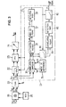
- the figure 1 shows an OFDM system with the modem of the transmitter 1 and that of the receiver 2 separated by a transmission channel 3.
- the modem On the transmitter 1 side, the modem has a unit 11 for building blocks and successive frames of real symbols a n, m .
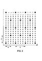
- the block has a duration Q of four OFDM / OQAM / IOTA symbols (an OFDM / OQAM / IOTA symbol consists of at most 2M real symbols a n, m ).
- Large black dots denote pilot symbols inserted at particular locations in the block, divided into time and frequency.
- the pilot symbols have real values that are known or determinable by the different modems of the system, as well as their positions in time and frequency.
- the small black dots denote useful data symbols and the rectangles of the null values on unallocated subcarriers.
- the number P designates the frequency spacing of the pilot symbols, in units of ⁇ 0 .
- the number Q denotes the time spacing of the pilot symbols, in units of ⁇ 0 .
- the number R denotes the time spacing between OFDM / OQAM / IOTA symbols containing pilot symbols, in units of ⁇ 0 .
- the blocks constructed by the unit 11 are supplied to an OFDM modulator comprising the units 12-14 shown on the figure 1 .
- the unit 12 applies to the symbols a n, m the term of phase rotation j n + m of the expression (1).
- FFT -1 inverse fast Fourier transform
- These quantities are filtered by the IOTA waveform in the filter 14.
- the resulting OFDM signal E (t) is then converted into analog (digital-to-analog converter 15) and then transposed on a transmission carrier of frequency fp in the radio stage 16 before being transmitted on channel 3.
- the receiver 2 shown schematically on the figure 1 a synchronization unit 21 located upstream of the demodulator comprising the IOTA filter 22 corresponding to that 14 of the transmitter, the Fast Fourier Transform (FFT) unit 23 and the phase rotation unit 24 which multiplies the values Complexes from the FFT by j -nm to recover, after projection on the real axis, the estimate of n, m of the symbols transmitted to n, m .
- FFT Fast Fourier Transform
- the nominal value of the sampling frequency F e may be 3.84 MHz.
- the synchronization unit 21 shown in more detail on the figure 3 , operates on the digital output of the converter 29.
- a numerically controlled oscillator (NCO, "numerically controlled oscillator”) 26 outputs the waveform c (t) at a frequency f c as close as possible to the carrier frequency fp used by the transmitter in order to optimize receiver performance .
- NCO numerically controlled oscillator
- the synchronization unit can tolerate a certain difference between the frequencies f c and f p .
- the complex function (2 I , 2 Q ) has the property of being invariant by static phase rotation resulting from a delay or a residual carrier frequency difference between transmission and reception. This is not the case in the presence of significant frequency differences vis-à-vis the period T (of the order of kHz in our example). In this case, the signal-to-noise ratio of the correlation function decreases sharply and the time synchronization depends to a large extent on the prior operation of frequency synchronization, which itself also depends on the time synchronization.
- One way to solve this problem is to split the correlation operation into several operations performed on sections of the reference pattern corresponding to the pilot symbols.
- the computation of the correlations then comprises, for each time position p, the estimation of a partial correlation between the baseband complex signal and each of the sections of the reference pattern.
- K 16 real terms
- K 16 imaginary terms
- the registers 33 I , 33 Q , 31 I and 31 Q are shown twice to facilitate the reading of the drawing, but they are naturally present in one copy each.
- the shape of the correlation signal C ** (p) is represented as a function of time on the figure 5 .
- This signal comprises a fundamental peak, which is statistically the one of higher level, as well as parasitic peaks spaced from T / 16 due to the time-frequency distribution of the pilot symbols.
- the signal is affected by a noise N **, represented in thick line, due to the data associated with the pilot sequence, as well as the channel disturbances. It is not always easy to directly discriminate the fundamental peak, which may be affected by an amplitude variation that may place it below the neighboring parasite peaks. To avoid this problem, formatting can be performed in circuit 37.
- the shaping circuit 37 comprises six elements 50-55, represented on the figure 6 , in order to increase the signal-to-noise ratio of the correlation signal and thus the amplitude difference between the main peak and the parasitic peaks.
- SFN Single Frequency Network
- hysteresis function allows the receiver to lock on one of the two paths and not to change any more.
- the second element 51 performs an infinite impulse response filtering (RII) by weighted average, with a forgetting factor ⁇ , samples of the signal, of 4 symbols in 4 symbols.
- This operation increases the signal-to-noise ratio of the correlation signal, and provides confidence information on the detection of the peak of the highest level.
- the input signal of the element 51 is added together with the delayed version of the output of a period T, weighted by a factor ⁇ . Due to the independence of correlation noise at the 1024 sample level, the signal-to-noise (S / N) gain increases when applies a factor ⁇ close to 1.
- S / N Due to the independence of correlation noise at the 1024 sample level, the signal-to-noise (S / N) gain increases when applies a factor ⁇ close to 1.
- a too large memory effect can be a disadvantage in the acquisition phase or to switch to a reception signal of higher level.
- the elements 52 and 54 perform a non-linear amplification of the signal which particularly amplifies the highest levels of the signal. This increases the difference in level between the main peak and the neighboring peaks, and reduces the noise at low amplitudes. This improves the level combining operations performed in the elements 53 and 55.
- the elements 53 and 55 take advantage of the symmetry of the correlation response with respect to the central peak to attenuate the adjacent peaks.
- the function of the element 53 has for example for expression: VS p + min ⁇ VS ⁇ p - 64 , VS ⁇ p + 64 + min ⁇ VS ⁇ p - 128 , VS ⁇ p + 128 while that of element 55 has for example for expression: VS p - VS ⁇ p - 64 + VS ⁇ p - 128 - VS ⁇ p + 64 - VS ⁇ p + 128
- the signal C "'(p) obtained after the various operations performed in the shaping circuit 37 is illustrated by the figure 7 .
- the ratio between the lowest level of the central peak and the highest level of adjacent spurious peaks is at least 6 dB, regardless of the channel, Gaussian or variable, with high noise levels and high frequency deviation. This 6dB margin is largely sufficient to ensure the robustness of the synchronization throughout the operating range of the transceiver system.
- the last operation of extraction of the symbol synchronization detects the fundamental peak over a period of four OFDM / OQAM symbols which corresponds to 1024 samples in the example under consideration, and restores a synchronization peak in the period following of 1024 samples.
- the circuit 38 can operate according to the algorithm represented on the figure 8 , clocked by a modulo counter 1024, which is the number of samples C "'(p) in a period of four symbols.
- the detection of the maximum is carried out on the correlation signal C "'(p) shaped by the circuit 37.
- the indexes p and q are set to zero and the variable MAX receives the value C". (0) the correlation signal.
- the index p is incremented by one unit in step 61, then the value C "'(p) of the correlation signal is compared to MAX (test 62) If C"' (p)> MAX, the index q receives the value of the index p in step 63 and the variable MAX is updated with the value C "'(p) After step 63, or when C"' (p)> MAX at In test 62, the algorithm examines in test 64 whether the index p and the POSITION variable have the same value.
- step 65 If so, a timing peak is produced in step 65.
- the POSITION variable receives the value of the index q in step 67, then the algorithm returns to the initialization step 60 to start the symbol synchronization on the next period T.
- the frame synchronization occurs after the temporal synchronization of the symbols. It makes it possible to identify the received symbols and thus to carry out, downstream of the demodulator 22-24, the important stripping operations which condition, among other things, the decoding of the data.
- the frame synchronization also takes advantage of the computation of the complex correlation between the input signal and the reference pattern of the pilots by exploiting the phase of the correlation.
- the frame lasts for 60 OFDM / OQAM / IOTA symbols. All four symbols a phase law is applied to the pilot symbols on transmission. The application of this phase law recursively every 15 blocks of 4 symbols gives a particular structure to the sequence. At the reception, an additional correlation operation on this particular structure sequence, when the correlation peaks are well localized thanks to the time synchronization, then makes it possible to ensure the frame synchronization.
- the frame synchronization sequence has good autocorrelation properties.
- the unit 11 inserts pilot symbols modulated in phase, in blocks of 4 symbols, by a simple change of sign (so that the pilot symbols remain real in the example considered), with the following PN sequence: [0,0,0,1,0,0,1,1,0,1,0,1,1,1].
- the first three blocks of 4 OFDM / OQAM symbols have pilot symbols issued without a sign change, those of the fourth block have their sign reversed, and so on.
- the inverse operation is applied on the distributed pilots to compensate this phase law before the channel estimation.
- This method has the advantage of not requiring additional information to be included in the signal for frame synchronization purposes. In addition, it does not disturb clock and symbol synchronizations that take into account the module of the correlation function but not its phase.
- the phase of the correlation signal is mainly exploitable at the time of the main peak.
- a sampler 80 ( figure 3 ) samples each main peak from the delayed symbol synchronization peak obtained at the output of the detection circuit 38, in order to make it possible to analyze the phase variations of the maximized complex correlations. So that the symbol synchronization can work in the presence of a possible difference in frequency, a peak provides 16 complex values all 1024 samples output of the correlation calculation circuit 30.
- the sampler 80 delivers during the k-th period T 1024 samples, that is to say for the k-th block received, an information C * (k) corresponding to the sum of the 16 complex values.
- the actual parts I VS * k and imaginary Q VS * k of this information C * (k) are those of the expression (2 I , 2 Q ) above, at the instant p of the principal peak detected by the circuit 38 during the kth period. This is the result of a global correlation operation performed on 1024 samples.
- the unit 81 for calculating the frame correlation intervenes after the sampler 80 and has, for example, the structure represented on the FIG. figure 9 .
- Block 130 of unit 81 takes into account the phase changes of a correlation peak at the next correlation peak.
- the PN sequence remains invariant and the frame synchronization can take place even in the presence of a moderate residual frequency deviation.
- block 130 does not make a hard decision. Its output signal is subjected to an RII filter 140 before proceeding to calculate the frame correlation in the block 150.
- the unit 81 obtains an amount representative of the phase variation between the complex correlations C * (k). New correlations are then calculated between these quantities and a sequence corresponding to the phase modulation of the pilot symbols from one block to another. A maximization of these correlations will make it possible to locate the received frames in time.
- the phase modulation of the pilot symbols from one block to another is a sign change modulation
- the representative amount of the phase variation is binary. It can represent the sign of a real signal obtained by filtering a signal obtained by combining the real and imaginary parts of the complex correlations C * (k-1), C * (k) for two consecutive blocks k-1, k .
- C * (k) A (k) .ej. ⁇ (k) with A (k) real positive
- C Tr (k) [A (k) .A (k-1)]. cos [ ⁇ (k) - ⁇ (k-1)].
- a phase shift of ⁇ ⁇ in the calculated correlation C * (k) (due to the time modulation of the pilot symbols) reverses the sign of cos [ ⁇ (k) - ⁇ (k-1)] and results in a sign change of C Tr (k).
- the confidence in the detection of the phase change of ⁇ ⁇ is all the greater as the modules A (k-1) and A (k) are of large amplitude. It will be observed that other expressions can be used for the sign change detection.
- the filtering RII produced by the filter 140 is similar to that carried out in the element 51 of the figure 6 , with a shift register 141 of only 15 positions, the output of which is supplied to a multiplier 142 which applies a coefficient ⁇ to it.
- An adder 143 has its two inputs connected to the output of the sign change detection block 130 and that of the multiplier 142.
- the gain in signal-to-noise ratio is of the order of 15 dB.
- the sign bits of the coefficients C Tr * (i + k-15) can be taken at the corresponding positions of the shift register 141 of the RII filter 140.
- the bits P Tr (i) are the binary values of the frame synchronization PN sequence.
- the frame synchronization is not lost when switching from one path to another in the receive configuration of a multi-path channel, and one can keep a important memory effect in continuous operation.
- the detection circuit of maximum 82 ( figure 3 ) analyze the signal C Tr * (k) produced by the unit 81.
- This circuit 82 is similar to the circuit 38 described above, with the only difference being controlled by a modulo counter 15 at the rate of the blocks.
- This block provides a frame synchronization top of duration 1024 samples every 15 blocks of 4 symbols, as well as the value of the maximum obtained at the end of the count.
- This frame synchronization top undergoes an AND logic operation with the symbol synchronization top delivered by the circuit 38 (block 83) to be reduced to a duration of a sample at F e so that it can be directly exploited by the receiver.
- the value of the correlation maximum detected by the circuit 82 can also be used to provide the receiver with information on the state of synchronization.
- the different synchronizations are established in the following order: symbol synchronization, then clock and frequency synchronizations and finally frame synchronization. Regardless of the channel, Gaussian or variable, and even with high noise levels, the maximum value of 15 of the frame correlation product is reached.
- Exceeding a detection threshold (for example 13) on the maximum detected by the circuit 82 may therefore constitute reliable information on the overall state of the synchronization and serve to reset other functions of the receiver.
- the exemplary embodiment of the synchronization described above has a very moderate hardware implementation complexity compared to the other signal processing operations performed in a digital receiver.
- Another advantage is the maintenance of the frame synchronization in case of switching from one path to another in the reception configuration of a multi-path channel.
Abstract
Description
La présente invention concerne les transmissions de signaux numériques multiporteuse, et notamment la synchronisation du récepteur d'un tel signal.The present invention relates to transmissions of multicarrier digital signals, and in particular the synchronization of the receiver of such a signal.
La synchronisation d'un récepteur numérique est un problème important, qui présente plusieurs aspects:
- synchronisation symbole, consistant à délimiter dans le temps les symboles numériques transmis en délivrant des tops symbole alignés sur ceux de l'émetteur;
- synchronisation d'horloge (ou récupération de rythme), consistant à régler la fréquence d'échantillonnage du récepteur afin d'échantillonner le signal reçu aux meilleurs instants;
- synchronisation trame, consistant à repérer les structures de données utilisées par l'émetteur parmi l'ensemble des symboles reçus, afin de détramer les données et permettre leur décodage;
- synchronisation fréquentielle (ou récupération de porteuse), consistant à corriger la haute fréquence utilisée par le récepteur pour ramener le signal reçu en bande de base en éliminant les écarts de fréquence avec la porteuse utilisée par l'émetteur.
- symbol synchronization, consisting in delimiting in time the digital symbols transmitted by delivering symbol tops aligned with those of the transmitter;
- clock synchronization (or clock recovery), of setting the sampling frequency of the receiver to sample the received signal at the best times;
- frame synchronization, consisting in locating the data structures used by the transmitter among the set of received symbols, in order to destroy the data and enable their decoding;
- frequency synchronization (or carrier recovery), of correcting the high frequency used by the receiver to bring the received baseband signal back by eliminating frequency differences with the carrier used by the transmitter.
On s'intéresse ici aux signaux multiporteuse de type OFDM ("Orthogonal Frequency Division Multiplexing", multiplexage par répartition orthogonale de fréquence). Les techniques OFDM sont bien connues et utilisées dans de nombreux systèmes de communication numérique (ADSL, WIFI, etc.) et dans des systèmes de diffusion numérique (DAB, DVB-T, DRM, etc.).We are interested here in OFDM (Orthogonal Frequency Division Multiplexing) multi-carrier signals. OFDM techniques are well known and used in many digital communication systems (ADSL, WIFI, etc.) and in digital broadcasting systems (DAB, DVB-T, DRM, etc.).
La transmission d'un signal OFDM comporte habituellement une transformée de Fourier rapide inverse (FFT-1) effectuée par l'émetteur sur un groupe de symboles à transmettre. Le résultat de la transformée, éventuellement mis en forme par filtrage, est transposé sur une fréquence porteuse pour être émis sur un canal. Le récepteur effectue une transformée de Fourier rapide (FFT, "Fast Fourier Transform") après transposition du signal reçu en bande de base pour évaluer les symboles transmis.The transmission of an OFDM signal usually comprises an inverse fast Fourier transform (FFT -1 ) carried out by the transmitter on a group of symbols to be transmitted. The result of the transform, possibly formatted by filtering, is transposed on a frequency carrier to be transmitted on a channel. The receiver performs a Fast Fourier Transform (FFT) after transposing the received baseband signal to evaluate the transmitted symbols.
Les symboles transmis par multiplexage OFDM peuvent être modulés selon divers types de modulation. On considérera ci-après des modulations par déplacement d'amplitude en quadrature, ou QAM ("Quadrature Amplitude Modulation"), dont la modulation par déplacement de phase en quadrature (QPSK, "Quadrature Phase Shift Keying") est un cas particulier, et notamment des modulations QAM décalées (OQAM, "Offset Quadrature Amplitude Modulation"). Les modulations OFDM/QAM et OFDM/OQAM sont bien connues. Voir par exemple:
Les signaux OFDM classiques comportent une succession d'intervalles de temps correspondant à des symboles transmis et séparés les uns des autres par des intervalles de garde servant à limiter les interférences entre symboles. En général, le signal des intervalles de symboles est étendu de manière cyclique dans les intervalles de garde. Un intérêt des modulations OFDM/OQAM est d'avoir permis de se dispenser des intervalles de garde, ce qui apporte un gain en efficacité spectrale.The conventional OFDM signals comprise a succession of time intervals corresponding to symbols transmitted and separated from each other by guard intervals serving to limit intersymbol interference. In general, the signal of the symbol intervals is extended cyclically in the guard intervals. An advantage of OFDM / OQAM modulations is to have been able to dispense with guard intervals, which brings a gain in spectral efficiency.
Les techniques connues de synchronisation d'un signal OFDM, par exemple selon
Ces techniques de synchronisation connues sont mises en défaut lorsque le signal OFDM ne présente pas d'intervalles de garde, comme c'est le cas avec les modulations OFDM/OQAM.These known synchronization techniques are faulted when the OFDM signal has no guard intervals, as is the case with OFDM / OQAM modulations.
En outre, elles ne donnent pas accès à une bonne synchronisation avant que l'opération de FFT soit effectuée dans le récepteur.In addition, they do not give access to good synchronization before the FFT operation is performed in the receiver.
Le présent document concerne notamment une technique de synchronisation trame moins affectée par les limitations ci-dessus.This document relates in particular to a frame synchronization technique less affected by the above limitations.
Il est présenté un procédé d'émission d'un signal OFDM, comprenant les étapes suivantes:
- distribuer sur plusieurs sous-porteuses et dans le temps un ensemble de symboles numériques à transmettre pour former des trames successives, chaque trame comprenant plusieurs blocs successifs de symboles;
- incorporer des symboles pilotes répartis en temps et en fréquence parmi les symboles à transmettre;
- moduler la phase des symboles pilotes d'un bloc à un autre avec la périodicité des trames; et
- appliquer aux dits symboles un schéma de modulation OFDM.
- distributing over a plurality of sub-carriers and over time a set of digital symbols to be transmitted to form successive frames, each frame comprising several successive blocks of symbols;
- incorporating pilot symbols distributed in time and frequency among the symbols to be transmitted;
- modulating the phase of the pilot symbols from one block to another with the periodicity of the frames; and
- apply to said symbols an OFDM modulation scheme.
Les symboles pilotes à l'intérieur des blocs permettent au récepteur de repérer dans le temps ces blocs et les symboles qu'ils contiennent. La modulation de la phase des symboles pilotes, d'un bloc à un autre à l'échelle des trames, permet ensuite de repérer les trames pour que le décodage des données transmises puisse s'opérer.The pilot symbols inside the blocks allow the receiver to locate these blocks and the symbols they contain in time. The modulation of the phase of the pilot symbols, from one block to another at the frame scale, then makes it possible to locate the frames so that the decoding of the transmitted data can take place.
Un autre aspect de la présente invention se rapporte à un procédé de réception d'un signal OFDM émis de cette manière. Le procédé de réception comporte une opération de synchronisation qui comprend les étapes suivantes:
- calculer des corrélations complexes, pour différentes positions temporelles, entre un signal reçu et un motif de référence correspondant aux symboles pilotes répartis en temps et en fréquence;
- repérer dans le temps des blocs reçus par maximisation d'estimations en module des corrélations complexes calculées; et
- analyser des variations de phase des corrélations complexes calculées d'un bloc reçu à un autre pour repérer dans le temps des trames reçues.
- calculating complex correlations, for different temporal positions, between a received signal and a reference pattern corresponding to the pilot symbols distributed in time and in frequency;
- locating blocks received over time by maximizing estimates in modulus of calculated complex correlations; and
- analyzing phase variations of the complex correlations calculated from one received block to another for tracking received frames in time.
Ce procédé s'applique dans tous les systèmes OFDM, notamment ceux qui utilisent une modulation QAM ou OQAM, avec des pilotes de référence insérés dans les symboles à transmettre pour permettre l'estimation du canal de propagation au niveau du récepteur. La solution proposée utilise les fonctions de corrélation entre un motif de référence qui est stocké dans la mémoire du récepteur et le signal OFDM reçu. Le motif de référence correspond au signal OFDM dans le domaine temporel avec uniquement les pilotes de référence dont les caractéristiques sont connues par le récepteur.This method applies in all OFDM systems, in particular those using QAM or OQAM modulation, with reference pilots inserted in the symbols to be transmitted to allow estimation of the propagation channel at the receiver. The proposed solution uses the correlation functions between a reference pattern that is stored in the receiver's memory and the received OFDM signal. The reference pattern corresponds to the OFDM signal in the time domain with only the reference drivers whose characteristics are known by the receiver.
La synchronisation proposée repose sur des calculs de corrélations dans le domaine temporel avant transformée de Fourrier (FFT). Elle ne nécessite pas d'intervalle de garde, ni d'informations supplémentaires dédiées à la synchronisation. Elle peut être réalisée avec une complexité matérielle d'implantation très modérée.The proposed synchronization is based on correlations calculations in the time domain before Fourier transform (FFT). It does not require a guard interval or additional information dedicated to synchronization. It can be performed with a very moderate hardware complexity of implementation.
D'autres aspects de l'invention se rapportent à un émetteur et à un récepteur de signal OFDM mettant en oeuvre les procédés ci-dessus. L'émetteur comprend: une unité de construction de trames de symboles numériques à transmettre, distribués sur plusieurs sous-porteuses et dans le temps, des symboles pilotes répartis en temps et en fréquence étant incorporés parmi les symboles à transmettre; et un modulateur OFDM pour générer un signal OFDM à partir des trames de symboles. Chaque trame comprend plusieurs blocs successifs de symboles, la phase des symboles pilotes étant modulée d'un bloc à un autre avec la périodicité des trames.Other aspects of the invention relate to an OFDM transmitter and signal receiver embodying the above methods. The transmitter comprises: a digital symbol frame construction unit to be transmitted, distributed over several sub-carriers and over time, pilot symbols distributed in time and in frequency being incorporated among the symbols to be transmitted; and an OFDM modulator for generating an OFDM signal from the symbol frames. Each frame comprises several successive blocks of symbols, the phase of the pilot symbols being modulated from one block to another with the periodicity of the frames.
Le récepteur a une unité de synchronisation comprenant: un circuit de calcul de corrélations complexes entre un signal reçu et un motif de référence correspondant aux symboles pilotes répartis en temps et en fréquence; des circuits pour repérer dans le temps des blocs reçus par maximisation d'estimations en module des corrélations complexes calculées; et des circuits pour analyser des variations de phase des corrélations complexes calculées d'un bloc reçu à un autre pour repérer dans le temps des trames reçues. L'unité de synchronisation peut être placée en amont d'un démultiplexeur à transformée de Fourier dont est muni le récepteur pour extraire des composantes fréquentielles du signal OFDM.The receiver has a synchronization unit comprising: a circuit for calculating complex correlations between a received signal and a reference pattern corresponding to the pilot symbols distributed in time and in frequency; circuitry for time-tracking blocks received by maximizing module estimates of computed complex correlations; and circuitry for analyzing phase variations of complex correlations calculated from one received block to another for tracking received frames in time. The synchronization unit may be placed upstream of a Fourier transform demultiplexer provided by the receiver for extracting frequency components of the OFDM signal.
D'autres particularités et avantages de la présente invention apparaîtront dans la description ci-après d'exemples de réalisation non limitatifs, en référence aux dessins annexés, dans lesquels :
- la
figure 1 est un schéma synoptique d'un système de transmission OFDM selon un mode de réalisation; - la
figure 2 est un diagramme illustrant une structure possible pour des blocs OFDM dans le système de lafigure 1 , - la
figure 3 est un schéma synoptique d'une unité de synchronisation utilisable dans un récepteur du système de lafigure 1 ; - la
figure 4 est un schéma synoptique d'une réalisation possible d'un circuit de calcul de corrélations; - la
figure 5 est un graphique montrant la forme d'un signal de corrélation dans un mode de réalisation de l'unité de synchronisation; - la
figure 6 est un schéma synoptique d'un circuit de mise en forme utilisable dans une réalisation de l'unité de synchronisation; - la
figure 7 est un graphique montrant la forme du signal de corrélation après mise en forme; - la
figure 8 est un organigramme d'un algorithme de détection de maximum de corrélation utilisable dans une réalisation de l'unité de synchronisation; - la
figure 9 est un schéma synoptique d'une unité de calcul de corrélation trame utilisable dans une réalisation de l'unité de synchronisation; - la
figure 10 est un graphique illustrant l'autocorrélation d'un exemple de séquence PN de synchronisation trame.
- the
figure 1 is a block diagram of an OFDM transmission system according to one embodiment; - the
figure 2 is a diagram illustrating a possible structure for OFDM blocks in the system of thefigure 1 , - the
figure 3 is a synoptic diagram of a synchronization unit usable in a receiver of the system of thefigure 1 ; - the
figure 4 is a block diagram of a possible realization of a correlation calculation circuit; - the
figure 5 is a graph showing the form of a correlation signal in one embodiment of the synchronization unit; - the
figure 6 is a block diagram of a shaping circuit that can be used in one embodiment of the synchronization unit; - the
figure 7 is a graph showing the shape of the correlation signal after shaping; - the
figure 8 is a flowchart of a maximum correlation detection algorithm usable in one embodiment of the synchronization unit; - the
figure 9 is a block diagram of a frame correlation calculation unit usable in one embodiment of the synchronization unit; - the
figure 10 is a graph illustrating the autocorrelation of an exemplary frame sync PN.
Un récepteur OFDM est décrit ci-après dans le cas particulier d'une modulation de type OQAM. La technique décrite est cependant applicable à tout type de modulation dans un système OFDM. Un signal OFDM/OQAM a pour expression, en bande de base: 
où t représente le temps continu, l'entier n est l'index temporel des symboles, l'entier m indexe les sous-porteuses OFDM dont le nombre maximum est 2M, an,m est un symbole réel à modulation d'amplitude, τ0 est la durée d'un symbole et ν0 est l'intervalle fréquentiel entre sous-porteuses. Les modulations OQAM utilisent des symboles an,m réels avec une durée de symbole τ0 deux fois plus courte que dans le cas d'une modulation OFDM/QAM non décalée (où les symboles sont complexes et le terme de rotation de phase jn+m n'est pas présent).An OFDM receiver is described below in the particular case of an OQAM type modulation. The technique described is however applicable to any type of modulation in an OFDM system. An OFDM / OQAM signal is expressed in baseband as:
where t represents the continuous time, the integer n is the temporal index of the symbols, the integer m indexes the OFDM sub-carriers whose maximum number is 2M, a n, m is a real symbol with amplitude modulation, τ 0 is the duration of a symbol and ν 0 is the frequency interval between subcarriers. OQAM modulations use actual symbols a n, m with a symbol duration τ 0 which is twice as short as in the case of non-shifted OFDM / QAM modulation (where the symbols are complex and the term of phase rotation j n + m is not present).
Dans l'expression (1) du signal OFDM en bande de base, g(t-nτ0) est une fonction de mise en forme dont un exemple est la fonction IOTA "Isotropic Orthogonal Transform Algorithm") décrite notamment dans l'article "
- la forme d'onde IOTA et sa transformée de Fourier sont identiques;
- les lobes secondaires de la fonction IOTA s'amortissent plus rapidement que ceux d'une fonction rectangulaire, ce qui permet de tronquer la forme d'onde sur une durée plus courte;
- la mise en forme spectrale des sous-porteuses qui sont localisées de façon optimale dans les domaines temps-fréquence offre une bonne résistance aux effets d'un canal multi-trajets ainsi qu'aux effets Doppler sans intervalle de garde. On a donc un gain en efficacité spectrale par rapport à l'OFDM classique car il n'y a plus de redondance. On peut ainsi prendre τ0.ν0 = 1/2.
- the IOTA waveform and its Fourier transform are identical;
- the secondary lobes of the IOTA function are amortized faster than those of a rectangular function, which makes it possible to truncate the waveform for a shorter duration;
- the spectral shaping of the sub-carriers which are optimally localized in the time-frequency domains offers good resistance to the effects of a multipath channel as well as Doppler effects without guard interval. We therefore have a gain in spectral efficiency compared to conventional OFDM because there is no more redundancy. We can thus take τ 0 .ν 0 = 1/2.
La
La
Les blocs construits par l'unité 11 sont fournis à un modulateur OFDM comprenant les unités 12-14 représentées sur la 
Le récepteur 2 représenté schématiquement sur la
Le signal S(t) reçu en entrée du récepteur 2, supposé sans bruit additif, est proportionnel à E(t).p(t), où p(t) = e2jπfpt = eφ(t) est la porteuse d'émission. Le circuit mélangeur 28 combine le signal OFDM reçu à une onde c(t) = ej.(2πf
L'unité de synchronisation 21, représentée de façon plus détaillée sur la 
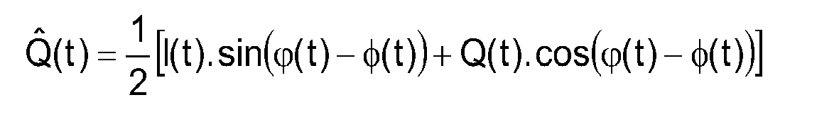
où I(t) et Q(t) désignent les parties réelle et imaginaire du signal OFDM/OQAM en bande de base E(t). Un écart de fréquence entre l'émetteur et le récepteur est complètement corrigé lorsque fp = fc, c'est-à-dire lorsque ϕ(t)-φ(t) est constant. Sinon, l'écart de fréquence résiduel laisse subsister une rotation de phase de 2π.(fc-fp).t dans le signal reçu en bande de base. Un oscillateur à commande numérique (NCO, "numerically controlled oscillator") 26 délivre l'onde c(t) à une fréquence fc aussi proche que possible de la fréquence porteuse fp utilisée par l'émetteur afin d'optimiser les performances du récepteur. Cependant, on verra que l'unité de synchronisation peut tolérer un certain écart entre les fréquences fc et fp.The
where I (t) and Q (t) denote the real and imaginary parts of the baseband OFDM / OQAM signal E (t). Frequency difference between transmitter and receiver is completely corrected when f p = f c , that is, when φ (t) -φ (t) is constant. Otherwise, the residual frequency deviation leaves a 2π phase rotation. (F c -f p) .t in the received signal to baseband. A numerically controlled oscillator (NCO, "numerically controlled oscillator") 26 outputs the waveform c (t) at a frequency f c as close as possible to the carrier frequency fp used by the transmitter in order to optimize receiver performance . However, it will be seen that the synchronization unit can tolerate a certain difference between the frequencies f c and f p .
L'unité de synchronisation 21 (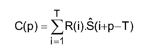
soit: 

is:
En termes de complexité matérielle, et en supposant un niveau de quantification volontairement réduit sur 6 bits signés par exemple, on constate qu'implanter directement cette opération présente encore un degré de complexité non négligeable puisqu'elle requiert notamment 4×1024 = 4096 multiplications sur 6 bits ainsi qu'une addition portant sur 4096 mots de 11 bits. Il est possible de réduire cette complexité en remplaçant les produits de corrélation par des produits binaires (XNOR) sur les bits de signe sI(i+p-T)=sgn{Î(i+p-T)} et sQ(i+p-T)=sgn{Q̂(i+p-T)} des composantes du signal reçu et sur les bits de signe rI(i)=sgn{IR(i)} et rQ(i)=sgn{QR(i)} des composantes du motif de référence, soit: 

Du fait des opérations de filtrage et de mise en forme qui suivent, les performances du système ne sont pas dégradées par cette simplification. Les parties réelle et imaginaire des motifs de référence, calculées une fois pour toutes (avec des zéros aux positions de tous les petits points noirs et les rectangles sur la
La fonction complexe (2I, 2Q) possède la propriété d'être invariante par rotation de phase statique résultant d'un retard ou d'un écart de fréquence porteuse résiduel entre émission et réception. Il n'en est pas de même en présence d'écarts de fréquence importants vis-à-vis de la période T (de l'ordre du kHz dans notre exemple). Dans ce cas, le rapport signal-à-bruit de la fonction de corrélation diminue fortement et la synchronisation temporelle dépend dans une large mesure de l'opération préalable de synchronisation fréquentielle, qui elle-même dépend aussi de la synchronisation temporelle.The complex function (2 I , 2 Q ) has the property of being invariant by static phase rotation resulting from a delay or a residual carrier frequency difference between transmission and reception. This is not the case in the presence of significant frequency differences vis-à-vis the period T (of the order of kHz in our example). In this case, the signal-to-noise ratio of the correlation function decreases sharply and the time synchronization depends to a large extent on the prior operation of frequency synchronization, which itself also depends on the time synchronization.
Une façon de résoudre ce problème consiste à scinder l'opération de corrélation en plusieurs opérations effectuées sur des tronçons du motif de référence correspondant aux symboles pilotes. A titre d'exemple, le motif de référence de 1024 échantillons est divisé en K = 16 tronçons de 64 échantillons chacun. Cet exemple permet d'assurer le fonctionnement de la synchronisation temporelle sur plusieurs dizaines de kHz, et en fait de l'ordre de +/-100 KHz pour des débits correspondant à une occupation spectrale d'environ 8 MHz.One way to solve this problem is to split the correlation operation into several operations performed on sections of the reference pattern corresponding to the pilot symbols. By way of example, the reference pattern of 1024 samples is divided into K = 16 sections of 64 samples each. This example ensures the operation of synchronization over several tens of kHz, and in fact of the order of +/- 100 KHz for rates corresponding to a spectral occupation of about 8 MHz.
Le calcul des corrélations comporte alors, pour chaque position temporelle p, l'estimation d'une corrélation partielle entre le signal complexe en bande de base et chacun des tronçons du motif de référence. En sortie du circuit 30, on compte donc K = 16 termes réels et K = 16 termes imaginaires, résultats de la corrélation partielle ![]()


![]()
Le circuit 30 peut alors avoir la constitution illustrée par la
- la référence 33I désigne un registre à décalage de 64 bits, scindé en K = 16 sous-registres montés en série 33I,1, 33I,2, ..., 33I,15, recevant les bits de signe des parties réelles échantillonnées Î(i) du signal reçu;
- la référence 33Q désigne un registre à décalage de 64 bits, scindé en K = 16 sous-registres montés en série 33Q,1, 33Q,2, ..., 33Q,15, recevant les bits de signe des parties imaginaires échantillonnées Q̂(i) du signal reçu;
la référence 31I désigne un registre de mémoire ROM de 64 bits scindé en K = 16 sous-registres la référence 31Q désigne un registre de mémoire ROM de 64 bits scindé en K = 16 sous-registres - chaque opérateur noté ⊗ réalise un produit binaire à chaque temps d'échantillon; et
- chaque additionneur noté ⊗ réalise l'une des sommes (3I) ou (3Q).
- 33 I denotes a 64-bit shift register, split into K = 16 subregisters connected in series 33 I, 1 , 33 I, 2 , ..., 33 I, 15 , receiving the sign bits of the parts actual sampled Î (i) of the received signal;
- 33 Q designates a 64-bit shift register, divided into K = 16 serially mounted sub-registers 33 Q, 1 , 33 Q, 2 , ..., 33 Q, 15 , receiving the sign bits of the parts imaginary sampled Q (i) of the received signal;
-
reference 31 I designates a 64-bit ROM memory register divided into K = 16sub-registers register 31 I, k containing the bits r I (i) representing the real part of the reference pattern for 64.k <i ≤ 64. (k + 1); -
reference 31 Q designates a 64-bit ROM memory register divided into K = 16sub-registers register 31 Q, k containing the bits r Q (i) representing the imaginary part of the reference pattern for 64.k <i ≤ 64. (k + 1); - each operator noted ⊗ realizes a binary product at each sample time; and
- each adder noted ⊗ realizes one of the sums (3 I ) or (3 Q ).
Sur la
La détection des pics de corrélation s'effectue ensuite, en principe, sur la base du module de C(p), estimé par le circuit 36 de l'unité de synchronisation 21 (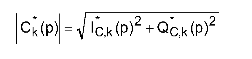
Une approximation de cette fonction de corrélation partielle peut être employée: 

Compte tenu de la corrélation fractionnée effectuée afin de rester indépendant d'un éventuel écart de fréquence porteuse, l'estimation en module C**(p) produite par le circuit 36 pour la détection de pics de corrélation consiste en la somme des K = 16 corrélations partielles estimées Dk(p): 
En sortie du circuit 36, l'allure du signal de corrélation C**(p) est représentée en fonction du temps sur la
Le circuit de mise en forme 37 comprend six éléments 50-55, représentés sur la
A partir de la détection d'un top symbole précédent, retardé de 1024 échantillons, l'élément 50 commute le gain du signal d'entrée C**(p) d'un facteur initial de 1 à un facteur 1+β de manière à créer de l'hystérésis sur la détection d'un maximum. A titre d'exemple, on peut prendre β = 1/4, ce qui produit une augmentation du gain d'environ 2 dB, le basculement d'un pic à un autre ne se produisant que si le nouveau pic présente un niveau supérieur de 2 dB par rapport au pic précédent. Après basculement, l'écart de niveau entre les deux pics en sortie est de 4 dB, ce qui évite une instabilité de commutation entre deux pics de niveaux assez proches. Une application ou cette fonction est très utile est la réception d'un signal SFN ("Single Frequency Network") comportant deux trajets de même puissance; dans ce cas la fonction d'hystérésis permet au récepteur de se caler sur un des deux trajets et de ne plus en changer.From the detection of a previous symbol top delayed by 1024 samples, the
Le deuxième élément 51 effectue un filtrage à réponse impulsionnelle infinie (RII) par moyenne pondérée, avec un facteur d'oubli α, des échantillons du signal, de 4 symboles en 4 symboles. Cette opération augmente le rapport signal à bruit du signal de corrélation, et apporte une information de confiance sur la détection du pic de plus fort niveau. Dans l'exemple de la
Les éléments 52 et 54 effectuent une amplification non linéaire du signal qui amplifie particulièrement les niveaux les plus élevés du signal. On augmente ainsi la différence de niveau entre le pic principal et les pics voisins, et on réduit le bruit aux faibles amplitudes. Ceci améliore les opérations de combinaison de niveau effectuées dans les éléments 53 et 55. Une opération d'amplification non-linéaire aisément implantable matériellement avec des valeurs quantifiées sur N bits fait correspondre à l'échantillon d'entrée Ee, l'échantillon de sortie Es tel que: 
où INT(x) désigne l'entier égal ou immédiatement inférieur à x. Il est possible d'augmenter l'effet d'expansion du signal en appliquant plusieurs fois cette opération. Dans l'exemple représenté, deux opérations d'expansion successives sont appliquées par les éléments 52 et 54.The
where INT (x) denotes the integer equal to or immediately smaller than x. It is possible to increase the signal expansion effect by applying this operation several times. In the example shown, two successive expansion operations are applied by
Les éléments 53 et 55 tirent parti de la symétrie de la réponse de corrélation par rapport au pic central pour atténuer les pics adjacents. La fonction de l'élément 53 a par exemple pour expression: ![]()
tandis que celle de l'élément 55 a par exemple pour expression: ![]()
![]()
while that of ![]()
Ces deux fonctions accentuent fortement l'atténuation par rapport au pic central. Le signal C"'(p) obtenu après les différentes opérations effectuées dans le circuit de mise en forme 37 est illustré par la
La dernière opération d'extraction de la synchronisation symbole, réalisée par le circuit 38, détecte le pic fondamental sur une période de quatre symboles OFDM/OQAM qui correspond à 1024 échantillons dans l'exemple considéré, et restitue un top de synchronisation dans la période suivante de 1024 échantillons. Le circuit 38 peut fonctionner suivant l'algorithme représenté sur la
La détection du maximum est effectué sur le signal de corrélation C"'(p) mis en forme par le circuit 37. A l'initialisation 60, les index p et q sont mis à zéro et la variable MAX reçoit la valeur C"'(0) du signal de corrélation. L'index p est incrémenté d'une unité à l'étape 61, puis la valeur C"'(p) du signal de corrélation est comparée à MAX (test 62). Si C"'(p) > MAX, l'index q reçoit la valeur de l'index p à l'étape 63 et la variable MAX est mise à jour avec la valeur C"'(p). Après l'étape 63, ou lorsque C"'(p) > MAX au test 62, l'algorithme examine au test 64 si l'index p et la variable POSITION ont la même valeur. Dans l'affirmative, un top de synchronisation est produit à l'étape 65. La valeur de l'index p est ensuite comparée à T-1 = 1023 (test 66). Tant que p < 1023, l'algorithme revient à l'étape 61 pour le prochain cycle de l'horloge d'échantillonnage. Lorsque p = 1023 au test 66, la variable POSITION reçoit la valeur de l'index q à l'étape 67 puis l'algorithme revient à l'étape d'initialisation 60 pour démarrer la synchronisation symbole sur la prochaine période T.The detection of the maximum is carried out on the correlation signal C "'(p) shaped by the
La synchronisation trame intervient après la synchronisation temporelle des symboles. Elle permet d'identifier les symboles reçus et ainsi d'effectuer, en aval du démodulateur 22-24, les opérations importantes de détramage qui conditionnent entre autres le décodage des données. Dans la réalisation décrite, la synchronisation trame tire également parti du calcul de la corrélation complexe entre le signal d'entrée et le motif de référence des pilotes en exploitant la phase de la corrélation.The frame synchronization occurs after the temporal synchronization of the symbols. It makes it possible to identify the received symbols and thus to carry out, downstream of the demodulator 22-24, the important stripping operations which condition, among other things, the decoding of the data. In the embodiment described, the frame synchronization also takes advantage of the computation of the complex correlation between the input signal and the reference pattern of the pilots by exploiting the phase of the correlation.
Dans l'exemple considéré, la trame dure 60 symboles OFDM/OQAM/IOTA. Tous les quatre symboles une loi de phase est appliquée aux symboles pilotes à l'émission. L'application de cette loi de phase de façon récurrente tous les 15 blocs de 4 symboles confère une structure particulière à la séquence. A la réception, une opération supplémentaire de corrélation sur cette séquence de structure particulière, lorsque les pics de corrélation sont bien localisés grâce à la synchronisation temporelle, permet alors d'assurer la synchronisation trame.In the example considered, the frame lasts for 60 OFDM / OQAM / IOTA symbols. All four symbols a phase law is applied to the pilot symbols on transmission. The application of this phase law recursively every 15 blocks of 4 symbols gives a particular structure to the sequence. At the reception, an additional correlation operation on this particular structure sequence, when the correlation peaks are well localized thanks to the time synchronization, then makes it possible to ensure the frame synchronization.
La séquence de synchronisation trame présente de bonnes propriétés d'auto-corrélation. Un exemple est constitué par la séquence de pseudo-bruit (PN, "pseudo-noise") utilisée, entre autres, dans les communications à étalement de spectre par séquence directe (DSSS, "direct sequence spread spectrum") et générée par le polynôme C15(x) = 1 + x3 + x4. A l'émission, l'unité 11 insère des symboles pilotes modulés en phase, par blocs de 4 symboles, par un simple changement de signe (pour que les symboles pilotes restent réels dans l'exemple considéré), avec la séquence PN suivante: [0,0,0,1,0,0,1,1,0,1,0,1,1,1,1]. Dans cet exemple, les trois premiers blocs de 4 symboles OFDM/OQAM ont des symboles pilotes émis sans changement de signe, ceux du quatrième bloc ont leur signe inversé, et ainsi de suite. A la réception, l'opération inverse est appliquée sur les pilotes répartis pour compenser cette loi de phase avant l'estimation de canal.The frame synchronization sequence has good autocorrelation properties. An example is the pseudo-noise (PN) sequence used, inter alia, in direct sequence spread spectrum (DSSS) communications generated by the polynomial C 15 (x) = 1 + x 3 + x 4 . On transmission, the unit 11 inserts pilot symbols modulated in phase, in blocks of 4 symbols, by a simple change of sign (so that the pilot symbols remain real in the example considered), with the following PN sequence: [0,0,0,1,0,0,1,1,0,1,0,1,1,1,1]. In this example, the first three blocks of 4 OFDM / OQAM symbols have pilot symbols issued without a sign change, those of the fourth block have their sign reversed, and so on. At the reception, the inverse operation is applied on the distributed pilots to compensate this phase law before the channel estimation.
Cette méthode a pour avantage de ne pas nécessiter d'information supplémentaire à inclure dans le signal aux fins de la synchronisation trame. En outre, elle ne perturbe pas les synchronisations horloge et symbole qui prennent en compte le module de la fonction de corrélation mais non sa phase.This method has the advantage of not requiring additional information to be included in the signal for frame synchronization purposes. In addition, it does not disturb clock and symbol synchronizations that take into account the module of the correlation function but not its phase.
La phase du signal de corrélation est principalement exploitable à l'instant du pic principal. En vue de réaliser la synchronisation trame, un échantillonneur 80 (
L'échantillonneur 80 délivre au cours de la k-ième période T de 1024 échantillons, c'est-à-dire pour le k-ième bloc reçu, une information C*(k) correspondant à la somme des 16 valeurs complexes. Les parties réelle ![]()
![]()
![]()
![]()
L'unité 81 de calcul de la corrélation trame intervient après l'échantillonneur 80 et présente par exemple la structure représentée sur la
Si la synchronisation trame peut intervenir après la synchronisation fréquentielle, il est utile que la synchronisation trame puisse être effectuée en présence d'un écart de phase statique entre émission et réception, et également en présence d'un écart de fréquence résiduel, de façon à accélérer l'acquisition de la synchronisation globale. Le bloc 130 de l'unité 81 prend en compte les changements de phase d'un pic de corrélation au pic de corrélation suivant. La séquence PN reste invariante et la synchronisation trame peut avoir lieu même en présence d'un écart de fréquence résiduel modéré. Pour éviter qu'une erreur de prise en compte entraîne deux erreurs de décision d'un changement de signe et augmenter le rapport signal à bruit, le bloc 130 ne prend pas de décision dure. Son signal de sortie est soumis à un filtre RII 140 avant de procéder au calcul de la corrélation trame dans le bloc 150.If the frame synchronization can occur after the frequency synchronization, it is useful that the frame synchronization can be performed in the presence of a static phase difference between transmission and reception, and also in the presence of a residual frequency difference, so as to accelerate the acquisition of global synchronization.
Pour chaque paire de blocs consécutifs, l'unité 81 obtient une quantité représentative de la variation de phase entre les corrélations complexes C*(k). De nouvelles corrélations sont ensuite calculées entre ces quantités et une séquence correspondant à la modulation de phase des symboles pilotes d'un bloc à un autre. Une maximisation de ces corrélations permettra de repérer dans le temps les trames reçues. Dans le cas décrit ici, la modulation de phase des symboles pilotes d'un bloc à un autre est une modulation par changement de signe, et la quantité représentative de la variation de phase est binaire. Elle peut représenter le signe d'un signal réel obtenu par filtrage d'un signal obtenu par combinaison des parties réelle et imaginaire des corrélations complexes C*(k-1), C*(k) pour deux blocs consécutifs k-1, k.For each pair of consecutive blocks, the
La détection de changement de signe à décision douce opérée par le bloc 130 peut notamment être régie par l'expression: 
Si on note C*(k) = A(k).ej.θ(k) avec A(k) réel positif, alors CTr(k) = [A(k).A(k-1)].cos[θ(k) - θ(k-1)]. En conséquence, un changement de phase de ±π dans la corrélation calculée C*(k) (due à la modulation dans le temps des symboles pilotes) inverse le signe de cos[θ(k) - θ(k-1)] et se traduit par un changement de signe de CTr(k). La confiance dans la détection du changement de phase de ±π est d'autant plus grande que les modules A(k-1) et A(k) sont de grande amplitude. On observera que d'autres expressions sont utilisables pour la détection de changement de signe.If we denote C * (k) = A (k) .ej.θ (k) with A (k) real positive, then C Tr (k) = [A (k) .A (k-1)]. cos [θ (k) - θ (k-1)]. As a result, a phase shift of ± π in the calculated correlation C * (k) (due to the time modulation of the pilot symbols) reverses the sign of cos [θ (k) - θ (k-1)] and results in a sign change of C Tr (k). The confidence in the detection of the phase change of ± π is all the greater as the modules A (k-1) and A (k) are of large amplitude. It will be observed that other expressions can be used for the sign change detection.
Dans l'exemple représenté sur la 
Le filtrage RII réalisé par le filtre 140 est analogue à celui effectué dans l'élément 51 de la 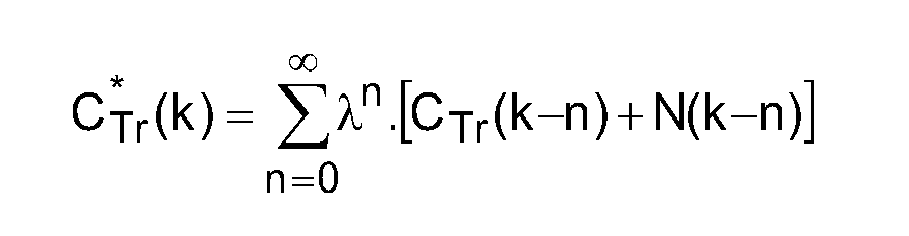
On a déterminé dans cet exemple qu'un facteur λ tel que 1-λ = 1/16 représente un bon compromis entre le gain vis-à-vis du bruit et un effet mémoire limité. Dans ce cas, le gain en rapport signal-à-bruit est de l'ordre de 15 dB.In this example, it has been determined that a factor λ such that 1-λ = 1/16 represents a good compromise between the gain with respect to the noise and a limited memory effect. In this case, the gain in signal-to-noise ratio is of the order of 15 dB.
En sortie du filtrage RII, une décision dure sur le changement de signe est prise, ce qui donne lieu à la quantité binaire précitée représentative de la variation de phase entre les corrélations complexes successives. Le produit de corrélation est calculé par le bloc 150 selon: 
où × représente le produit binaire effectué par une porte XNOR notée ⊗, la somme étant obtenue par l'élément noté ⊗. Les bits de signe des coefficients CTr*(i+k-15) peuvent être prélevés aux positions correspondantes du registre à décalage 141 du filtre RII 140. Les bits PTr(i) sont les valeurs binaires de la séquence PN de synchronisation trame, qui est invariante par différence de polarité. Dans l'exemple précédent, [PTr(1), ..., PTr(15)]= [0,0,0,1,0,0,1,1,0,1,0,1,1,1,1], ces quinze bits étant stockés dans un registre de mémoire 151. La fonction d'auto-corrélation R(PTr) de cette séquence est représentée sur la
where × represents the binary product carried out by an XNOR gate denoted ⊗, the sum being obtained by the element noted ⊗. The sign bits of the coefficients C Tr * (i + k-15) can be taken at the corresponding positions of the
Grâce au principe de détection de changement de signe et au filtrage RII, la synchronisation trame n'est pas perdue lors du basculement d'un trajet à un autre dans la configuration de réception d'un canal multi-trajet, et on peut conserver un effet mémoire important en fonctionnement continu.Thanks to the sign change detection principle and the RII filtering, the frame synchronization is not lost when switching from one path to another in the receive configuration of a multi-path channel, and one can keep a important memory effect in continuous operation.
Le circuit de détection de maximum 82 (
La valeur du maximum de corrélation détectée par le circuit 82, peut également être employée pour délivrer au récepteur une information sur l'état de la synchronisation. En phase d'acquisition, les différentes synchronisations s'établissent dans l'ordre suivant: synchronisation symbole, puis synchronisations horloge et fréquentielle et enfin synchronisation trame. Quel que soit le canal, gaussien ou variable, et même avec des niveaux de bruit élevés, la valeur maximale de 15 du produit de corrélation trame est atteinte. Le dépassement d'un seuil de détection (par exemple de 13) sur le maximum détecté par le circuit 82 peut donc constituer une information fiable sur l'état global de la synchronisation et servir pour réinitialiser d'autres fonctions du récepteur.The value of the correlation maximum detected by the
L'exemple de réalisation de la synchronisation décrit ci-dessus présente une complexité d'implantation matérielle très modérée au regard des autres opérations de traitement du signal effectuées dans un récepteur numérique.The exemplary embodiment of the synchronization described above has a very moderate hardware implementation complexity compared to the other signal processing operations performed in a digital receiver.
On a observé un seuil élevé d'apparition de fausses détections en présence de bruit de l'ordre de -6dB de rapport signal-à-bruit dans la bande passante du signal utile. Ceci excède largement les limites de fonctionnement des autres fonctions de traitement du signal du récepteur numérique.A high threshold of occurrence of false detections in the presence of noise of the order of -6 dB of signal-to-noise ratio in the bandwidth of the wanted signal has been observed. This greatly exceeds the operating limits of the other digital receiver signal processing functions.
Un autre avantage est le maintien de la synchronisation trame en cas de basculement d'un trajet à un autre dans la configuration de réception d'un canal multi-trajet.Another advantage is the maintenance of the frame synchronization in case of switching from one path to another in the reception configuration of a multi-path channel.
Claims (10)
dans lequel chaque trame comprend plusieurs blocs successifs de symboles, la phase des symboles pilotes étant modulée d'un bloc à un autre avec la périodicité des trames.
wherein each frame comprises several successive blocks of symbols, the phase of the pilot symbols being modulated from one block to another with the periodicity of the frames.

Applications Claiming Priority (2)
| Application Number | Priority Date | Filing Date | Title |
|---|---|---|---|
| FR0706485 | 2007-09-14 | ||
| EP08838067A EP2201735B1 (en) | 2007-09-14 | 2008-09-12 | Frame synchronisation in an ofdm communication system |
Related Parent Applications (1)
| Application Number | Title | Priority Date | Filing Date |
|---|---|---|---|
| EP08838067.0 Division | 2008-09-12 |
Publications (2)
| Publication Number | Publication Date |
|---|---|
| EP2445156A2 true EP2445156A2 (en) | 2012-04-25 |
| EP2445156A3 EP2445156A3 (en) | 2012-10-24 |
Family
ID=39493306
Family Applications (2)
| Application Number | Title | Priority Date | Filing Date |
|---|---|---|---|
| EP08838067A Active EP2201735B1 (en) | 2007-09-14 | 2008-09-12 | Frame synchronisation in an ofdm communication system |
| EP12151473A Withdrawn EP2445156A3 (en) | 2007-09-14 | 2008-09-12 | Frame synchronisation in an OFDM communication system |
Family Applications Before (1)
| Application Number | Title | Priority Date | Filing Date |
|---|---|---|---|
| EP08838067A Active EP2201735B1 (en) | 2007-09-14 | 2008-09-12 | Frame synchronisation in an ofdm communication system |
Country Status (3)
| Country | Link |
|---|---|
| EP (2) | EP2201735B1 (en) |
| AT (1) | ATE543313T1 (en) |
| WO (1) | WO2009047427A1 (en) |
Cited By (1)
| Publication number | Priority date | Publication date | Assignee | Title |
|---|---|---|---|---|
| CN106612163A (en) * | 2015-10-23 | 2017-05-03 | 中兴通讯股份有限公司 | Pilot signal transmission method, device and transmitting end |
Citations (2)
| Publication number | Priority date | Publication date | Assignee | Title |
|---|---|---|---|---|
| US20040146003A1 (en) | 2001-03-28 | 2004-07-29 | Wolfgang Schaefer | Method for frame and frequency synchronization of an ofdm signal and method for transmitting an ofdm signal |
| US20050036564A1 (en) | 2003-08-14 | 2005-02-17 | Stefan Peter | Method for processing an OFDM signal |
Family Cites Families (3)
| Publication number | Priority date | Publication date | Assignee | Title |
|---|---|---|---|---|
| DE60016074T2 (en) * | 1999-03-30 | 2005-11-24 | Nec Corp. | OFDM demodulator |
| US6711221B1 (en) * | 2000-02-16 | 2004-03-23 | Thomson Licensing S.A. | Sampling offset correction in an orthogonal frequency division multiplexing system |
| BRPI0516734A (en) * | 2004-10-01 | 2008-09-23 | Toshiba Kk Toshiba Corp | radio signal time measuring apparatus, transmission apparatus and relay apparatus using it, and time delay measuring apparatus |
-
2008
- 2008-09-12 AT AT08838067T patent/ATE543313T1/en active
- 2008-09-12 WO PCT/FR2008/051641 patent/WO2009047427A1/en active Application Filing
- 2008-09-12 EP EP08838067A patent/EP2201735B1/en active Active
- 2008-09-12 EP EP12151473A patent/EP2445156A3/en not_active Withdrawn
Patent Citations (2)
| Publication number | Priority date | Publication date | Assignee | Title |
|---|---|---|---|---|
| US20040146003A1 (en) | 2001-03-28 | 2004-07-29 | Wolfgang Schaefer | Method for frame and frequency synchronization of an ofdm signal and method for transmitting an ofdm signal |
| US20050036564A1 (en) | 2003-08-14 | 2005-02-17 | Stefan Peter | Method for processing an OFDM signal |
Non-Patent Citations (2)
| Title |
|---|
| B. LE FLOCH ET AL.: "Orthogonal frequency division multiplex", PROCEEDINGS OF THE IEEE, vol. 83, no. 6, June 1995 (1995-06-01), pages 982 - 996, XP000518747, DOI: doi:10.1109/5.387096 |
| D. LACROIX ET AL.: "OFDM with guard interval versus OFDM/offsetQAM for high data rate UMTS downlink transmission", VEHICULAR TECHNOLOGY CONFERENCE, OCTOBRE 2001, IEEE VTS 54TH, vol. 4, 2001, pages 2682 - 2686, XP002212791, DOI: doi:10.1109/VTC.2001.957247 |
Cited By (4)
| Publication number | Priority date | Publication date | Assignee | Title |
|---|---|---|---|---|
| CN106612163A (en) * | 2015-10-23 | 2017-05-03 | 中兴通讯股份有限公司 | Pilot signal transmission method, device and transmitting end |
| EP3382970A4 (en) * | 2015-10-23 | 2019-07-24 | ZTE Corporation | Pilot signal transmission method and apparatus, and transmitting terminal |
| US10574414B2 (en) | 2015-10-23 | 2020-02-25 | Zte Corporation | Pilot signal transmission method and apparatus, and transmitting terminal |
| CN106612163B (en) * | 2015-10-23 | 2020-05-01 | 中兴通讯股份有限公司 | Pilot signal transmission method and device and transmitting terminal |
Also Published As
| Publication number | Publication date |
|---|---|
| EP2201735B1 (en) | 2012-01-25 |
| WO2009047427A1 (en) | 2009-04-16 |
| EP2445156A3 (en) | 2012-10-24 |
| EP2201735A1 (en) | 2010-06-30 |
| ATE543313T1 (en) | 2012-02-15 |
Similar Documents
| Publication | Publication Date | Title |
|---|---|---|
| EP2503750B1 (en) | Method for processing a multicarrier signal with arrays of filters for synchronisation by preamble | |
| EP0879523B1 (en) | Method and apparatus for time synchronisation in a multi-carrier signal receiver | |
| EP2879341B1 (en) | Channel-estimation method for FBMC telecommunication system | |
| EP2499796B1 (en) | Method for transmitting pre-equalized digital data, and transmitting base implementing such a method | |
| EP0499560B1 (en) | Channel estimation system and method for COFDM transmission system | |
| EP1941547B1 (en) | Method for transmitting a multi-carrier signal designed for limiting interference, signal, emitting device, receiving method and device, and corresponding computer programs | |
| EP1969792B1 (en) | Dynamic interleaving method and device | |
| EP0441730A1 (en) | Method of data broadcasting with time-frequency interleaving, using frequency reference signals | |
| WO2016124841A1 (en) | Method and device for phase modulation of a carrier wave and application to the detection of multi-level phase-encoded digital signals | |
| WO2010029225A1 (en) | System for the multicarrier digital transmission of a signal using banks of filters and the preloading of memories for initialization | |
| EP2732592B1 (en) | Method and module for frequency bias estimation in a system for digital telecommunications | |
| EP1810470A1 (en) | Method for receiving a multicarrier signal using at least two estimations of a propagation channel and corresponding reception device | |
| EP1391095B1 (en) | Method for estimating the transfer function of a multicarrier signal transmission channel and corresponding receiver | |
| EP3232626A1 (en) | Transmitter for fbmc system with alamouti space-time block coding | |
| EP3202077B1 (en) | Method of sending a multicarrier signal, method of reception, devices, and computer programs associated therewith implementing an oqam type modulation | |
| FR2885471A1 (en) | METHOD FOR ITERATIVE DECODING OF OFDM / OQAM SIGNAL USING COMPLEX VALUE SYMBOLS, CORRESPONDING COMPUTER DEVICE AND PROGRAM | |
| EP2201735B1 (en) | Frame synchronisation in an ofdm communication system | |
| EP1081855B1 (en) | Synchronization method and apparatus of a communication receiver | |
| EP2146457A1 (en) | Method for temporal synchronisation of a digital signal, corresponding device and computer program product. | |
| EP2351305A2 (en) | Multi state with continuous phase modulation process and transmitter for this procces | |
| EP2153601B1 (en) | Method of synchronizing a multicarrier signal, corresponding emission method, devices and computer programs | |
| FR2702110A1 (en) | Method of automatic frequency control for receiving multi-carrier signals, and corresponding receiver | |
| WO2021053137A1 (en) | Method for marking a broadcast signal, method for identifying a marking signal, corresponding computer program products and corresponding devices | |
| FR2973617A1 (en) | Method for processing terrestrial digital TV signal carrying preamble symbol in digital video broadcasting-second generation terrestrial system, involves performing double-detection of prefixes and suffixes carried on digital TV signal |
Legal Events
| Date | Code | Title | Description |
|---|---|---|---|
| 17P | Request for examination filed |
Effective date: 20120117 |
|
| AC | Divisional application: reference to earlier application |
Ref document number: 2201735 Country of ref document: EP Kind code of ref document: P |
|
| AK | Designated contracting states |
Kind code of ref document: A2 Designated state(s): AT BE BG CH CY CZ DE DK EE ES FI FR GB GR HR HU IE IS IT LI LT LU LV MC MT NL NO PL PT RO SE SI SK TR |
|
| PUAI | Public reference made under article 153(3) epc to a published international application that has entered the european phase |
Free format text: ORIGINAL CODE: 0009012 |
|
| PUAL | Search report despatched |
Free format text: ORIGINAL CODE: 0009013 |
|
| AK | Designated contracting states |
Kind code of ref document: A3 Designated state(s): AT BE BG CH CY CZ DE DK EE ES FI FR GB GR HR HU IE IS IT LI LT LU LV MC MT NL NO PL PT RO SE SI SK TR |
|
| RIC1 | Information provided on ipc code assigned before grant |
Ipc: H04L 27/26 20060101AFI20120914BHEP |
|
| 17Q | First examination report despatched |
Effective date: 20121219 |
|
| RAP1 | Party data changed (applicant data changed or rights of an application transferred) |
Owner name: ORANGE |
|
| GRAP | Despatch of communication of intention to grant a patent |
Free format text: ORIGINAL CODE: EPIDOSNIGR1 |
|
| INTG | Intention to grant announced |
Effective date: 20131111 |
|
| STAA | Information on the status of an ep patent application or granted ep patent |
Free format text: STATUS: THE APPLICATION IS DEEMED TO BE WITHDRAWN |
|
| 18D | Application deemed to be withdrawn |
Effective date: 20140322 |