EP2445156A2 - Synchronisationsraster in einem OFDM-Kommunikationssystem - Google Patents
Synchronisationsraster in einem OFDM-Kommunikationssystem Download PDFInfo
- Publication number
- EP2445156A2 EP2445156A2 EP12151473A EP12151473A EP2445156A2 EP 2445156 A2 EP2445156 A2 EP 2445156A2 EP 12151473 A EP12151473 A EP 12151473A EP 12151473 A EP12151473 A EP 12151473A EP 2445156 A2 EP2445156 A2 EP 2445156A2
- Authority
- EP
- European Patent Office
- Prior art keywords
- symbols
- signal
- time
- received
- block
- Prior art date
- Legal status (The legal status is an assumption and is not a legal conclusion. Google has not performed a legal analysis and makes no representation as to the accuracy of the status listed.)
- Withdrawn
Links
- 238000004891 communication Methods 0.000 title description 3
- 238000000034 method Methods 0.000 claims abstract description 23
- 230000005540 biological transmission Effects 0.000 claims description 14
- 238000001914 filtration Methods 0.000 claims description 9
- 230000002123 temporal effect Effects 0.000 claims description 4
- 238000011144 upstream manufacturing Methods 0.000 claims description 3
- 238000004364 calculation method Methods 0.000 abstract description 5
- 238000001514 detection method Methods 0.000 description 16
- 230000006870 function Effects 0.000 description 14
- 230000014509 gene expression Effects 0.000 description 11
- 238000010586 diagram Methods 0.000 description 6
- 238000005070 sampling Methods 0.000 description 5
- 238000007493 shaping process Methods 0.000 description 5
- 238000012360 testing method Methods 0.000 description 5
- 239000000969 carrier Substances 0.000 description 4
- 238000005314 correlation function Methods 0.000 description 4
- 230000000694 effects Effects 0.000 description 4
- 230000010363 phase shift Effects 0.000 description 4
- 230000003595 spectral effect Effects 0.000 description 4
- 230000003111 delayed effect Effects 0.000 description 3
- 230000003446 memory effect Effects 0.000 description 3
- 241001632004 Tetrahymena sp. SIN Species 0.000 description 2
- 230000003321 amplification Effects 0.000 description 2
- 238000003199 nucleic acid amplification method Methods 0.000 description 2
- 230000003071 parasitic effect Effects 0.000 description 2
- 238000012545 processing Methods 0.000 description 2
- 238000011084 recovery Methods 0.000 description 2
- 230000004044 response Effects 0.000 description 2
- 230000003068 static effect Effects 0.000 description 2
- 101150012579 ADSL gene Proteins 0.000 description 1
- 102100020775 Adenylosuccinate lyase Human genes 0.000 description 1
- 108700040193 Adenylosuccinate lyases Proteins 0.000 description 1
- 101000860173 Myxococcus xanthus C-factor Proteins 0.000 description 1
- 239000000654 additive Substances 0.000 description 1
- 230000000996 additive effect Effects 0.000 description 1
- 238000005311 autocorrelation function Methods 0.000 description 1
- 238000010276 construction Methods 0.000 description 1
- 230000007423 decrease Effects 0.000 description 1
- 238000005516 engineering process Methods 0.000 description 1
- 238000000605 extraction Methods 0.000 description 1
- 238000005194 fractionation Methods 0.000 description 1
- 238000012423 maintenance Methods 0.000 description 1
- 239000000463 material Substances 0.000 description 1
- 244000045947 parasite Species 0.000 description 1
- 238000013139 quantization Methods 0.000 description 1
- 238000001228 spectrum Methods 0.000 description 1
Images


Classifications
-
- H—ELECTRICITY
- H04—ELECTRIC COMMUNICATION TECHNIQUE
- H04L—TRANSMISSION OF DIGITAL INFORMATION, e.g. TELEGRAPHIC COMMUNICATION
- H04L27/00—Modulated-carrier systems
- H04L27/26—Systems using multi-frequency codes
- H04L27/2601—Multicarrier modulation systems
- H04L27/2602—Signal structure
- H04L27/261—Details of reference signals
-
- H—ELECTRICITY
- H04—ELECTRIC COMMUNICATION TECHNIQUE
- H04L—TRANSMISSION OF DIGITAL INFORMATION, e.g. TELEGRAPHIC COMMUNICATION
- H04L27/00—Modulated-carrier systems
- H04L27/26—Systems using multi-frequency codes
- H04L27/2601—Multicarrier modulation systems
- H04L27/2647—Arrangements specific to the receiver only
- H04L27/2655—Synchronisation arrangements
- H04L27/2656—Frame synchronisation, e.g. packet synchronisation, time division duplex [TDD] switching point detection or subframe synchronisation
Definitions
- the present invention relates to transmissions of multicarrier digital signals, and in particular the synchronization of the receiver of such a signal.
- OFDM Orthogonal Frequency Division Multiplexing
- the transmission of an OFDM signal usually comprises an inverse fast Fourier transform (FFT -1 ) carried out by the transmitter on a group of symbols to be transmitted.
- FFT -1 inverse fast Fourier transform
- the result of the transform possibly formatted by filtering, is transposed on a frequency carrier to be transmitted on a channel.
- the receiver performs a Fast Fourier Transform (FFT) after transposing the received baseband signal to evaluate the transmitted symbols.
- FFT Fast Fourier Transform
- the symbols transmitted by OFDM multiplexing can be modulated according to various types of modulation.
- Quadrature Amplitude Modulation Quadrature Amplitude Modulation
- QPSK quadrature Phase Shift Keying
- OFAM offset QAM modulations
- the OFDM / QAM and OFDM / OQAM modulations are well known. See for example: B. Floch, et al., Orthogonal Frequency Division Multiplex, Proceedings of the IEEE, Vol. 83, No. 6, June 1995, pages 982-996 . It should be noted that the techniques described in this document are applicable to any type of modulation coupled to the OFDM technique.
- the conventional OFDM signals comprise a succession of time intervals corresponding to symbols transmitted and separated from each other by guard intervals serving to limit intersymbol interference.
- the signal of the symbol intervals is extended cyclically in the guard intervals.
- the known techniques for synchronizing an OFDM signal include several steps. First a coarse time synchronization is obtained based on the presence of the guard intervals. Then a finer synchronization is performed based on the information provided by the channel estimate after the FFT operation. The frame synchronization can finally be implemented by exploiting the correlation between a particular symbol that is inserted in the transmission frame and that is known by the receiver.
- This document relates in particular to a frame synchronization technique less affected by the above limitations.
- the pilot symbols inside the blocks allow the receiver to locate these blocks and the symbols they contain in time.
- the modulation of the phase of the pilot symbols, from one block to another at the frame scale, then makes it possible to locate the frames so that the decoding of the transmitted data can take place.
- This method applies in all OFDM systems, in particular those using QAM or OQAM modulation, with reference pilots inserted in the symbols to be transmitted to allow estimation of the propagation channel at the receiver.
- the proposed solution uses the correlation functions between a reference pattern that is stored in the receiver's memory and the received OFDM signal.
- the reference pattern corresponds to the OFDM signal in the time domain with only the reference drivers whose characteristics are known by the receiver.
- the proposed synchronization is based on correlations calculations in the time domain before Fourier transform (FFT). It does not require a guard interval or additional information dedicated to synchronization. It can be performed with a very moderate hardware complexity of implementation.
- FFT Fourier transform
- the transmitter comprises: a digital symbol frame construction unit to be transmitted, distributed over several sub-carriers and over time, pilot symbols distributed in time and in frequency being incorporated among the symbols to be transmitted; and an OFDM modulator for generating an OFDM signal from the symbol frames.
- Each frame comprises several successive blocks of symbols, the phase of the pilot symbols being modulated from one block to another with the periodicity of the frames.
- the receiver has a synchronization unit comprising: a circuit for calculating complex correlations between a received signal and a reference pattern corresponding to the pilot symbols distributed in time and in frequency; circuitry for time-tracking blocks received by maximizing module estimates of computed complex correlations; and circuitry for analyzing phase variations of complex correlations calculated from one received block to another for tracking received frames in time.
- the synchronization unit may be placed upstream of a Fourier transform demultiplexer provided by the receiver for extracting frequency components of the OFDM signal.
- An OFDM receiver is described below in the particular case of an OQAM type modulation. The technique described is however applicable to any type of modulation in an OFDM system.
- t represents the continuous time
- the integer n is the temporal index of the symbols
- the integer m indexes the OFDM sub-carriers whose maximum number is 2M
- a n m is a real symbol with amplitude modulation
- ⁇ 0 is the duration of a symbol
- ⁇ 0 is the frequency interval between subcarriers.
- OQAM modulations use actual symbols a n, m with a symbol duration ⁇ 0 which is twice as short as in the case of non-shifted OFDM / QAM modulation (where the symbols are complex and the term of phase rotation j n + m is not present).
- the figure 1 shows an OFDM system with the modem of the transmitter 1 and that of the receiver 2 separated by a transmission channel 3.
- the modem On the transmitter 1 side, the modem has a unit 11 for building blocks and successive frames of real symbols a n, m .
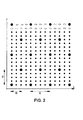
- the block has a duration Q of four OFDM / OQAM / IOTA symbols (an OFDM / OQAM / IOTA symbol consists of at most 2M real symbols a n, m ).
- Large black dots denote pilot symbols inserted at particular locations in the block, divided into time and frequency.
- the pilot symbols have real values that are known or determinable by the different modems of the system, as well as their positions in time and frequency.
- the small black dots denote useful data symbols and the rectangles of the null values on unallocated subcarriers.
- the number P designates the frequency spacing of the pilot symbols, in units of ⁇ 0 .
- the number Q denotes the time spacing of the pilot symbols, in units of ⁇ 0 .
- the number R denotes the time spacing between OFDM / OQAM / IOTA symbols containing pilot symbols, in units of ⁇ 0 .
- the blocks constructed by the unit 11 are supplied to an OFDM modulator comprising the units 12-14 shown on the figure 1 .
- the unit 12 applies to the symbols a n, m the term of phase rotation j n + m of the expression (1).
- FFT -1 inverse fast Fourier transform
- These quantities are filtered by the IOTA waveform in the filter 14.
- the resulting OFDM signal E (t) is then converted into analog (digital-to-analog converter 15) and then transposed on a transmission carrier of frequency fp in the radio stage 16 before being transmitted on channel 3.
- the receiver 2 shown schematically on the figure 1 a synchronization unit 21 located upstream of the demodulator comprising the IOTA filter 22 corresponding to that 14 of the transmitter, the Fast Fourier Transform (FFT) unit 23 and the phase rotation unit 24 which multiplies the values Complexes from the FFT by j -nm to recover, after projection on the real axis, the estimate of n, m of the symbols transmitted to n, m .
- FFT Fast Fourier Transform
- the nominal value of the sampling frequency F e may be 3.84 MHz.
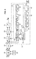
- the synchronization unit 21 shown in more detail on the figure 3 , operates on the digital output of the converter 29.
- a numerically controlled oscillator (NCO, "numerically controlled oscillator”) 26 outputs the waveform c (t) at a frequency f c as close as possible to the carrier frequency fp used by the transmitter in order to optimize receiver performance .
- NCO numerically controlled oscillator
- the synchronization unit can tolerate a certain difference between the frequencies f c and f p .
- the complex function (2 I , 2 Q ) has the property of being invariant by static phase rotation resulting from a delay or a residual carrier frequency difference between transmission and reception. This is not the case in the presence of significant frequency differences vis-à-vis the period T (of the order of kHz in our example). In this case, the signal-to-noise ratio of the correlation function decreases sharply and the time synchronization depends to a large extent on the prior operation of frequency synchronization, which itself also depends on the time synchronization.
- One way to solve this problem is to split the correlation operation into several operations performed on sections of the reference pattern corresponding to the pilot symbols.
- the computation of the correlations then comprises, for each time position p, the estimation of a partial correlation between the baseband complex signal and each of the sections of the reference pattern.
- K 16 real terms
- K 16 imaginary terms
- the registers 33 I , 33 Q , 31 I and 31 Q are shown twice to facilitate the reading of the drawing, but they are naturally present in one copy each.
- the shape of the correlation signal C ** (p) is represented as a function of time on the figure 5 .
- This signal comprises a fundamental peak, which is statistically the one of higher level, as well as parasitic peaks spaced from T / 16 due to the time-frequency distribution of the pilot symbols.
- the signal is affected by a noise N **, represented in thick line, due to the data associated with the pilot sequence, as well as the channel disturbances. It is not always easy to directly discriminate the fundamental peak, which may be affected by an amplitude variation that may place it below the neighboring parasite peaks. To avoid this problem, formatting can be performed in circuit 37.
- the shaping circuit 37 comprises six elements 50-55, represented on the figure 6 , in order to increase the signal-to-noise ratio of the correlation signal and thus the amplitude difference between the main peak and the parasitic peaks.
- SFN Single Frequency Network
- hysteresis function allows the receiver to lock on one of the two paths and not to change any more.
- the second element 51 performs an infinite impulse response filtering (RII) by weighted average, with a forgetting factor ⁇ , samples of the signal, of 4 symbols in 4 symbols.
- This operation increases the signal-to-noise ratio of the correlation signal, and provides confidence information on the detection of the peak of the highest level.
- the input signal of the element 51 is added together with the delayed version of the output of a period T, weighted by a factor ⁇ . Due to the independence of correlation noise at the 1024 sample level, the signal-to-noise (S / N) gain increases when applies a factor ⁇ close to 1.
- S / N Due to the independence of correlation noise at the 1024 sample level, the signal-to-noise (S / N) gain increases when applies a factor ⁇ close to 1.
- a too large memory effect can be a disadvantage in the acquisition phase or to switch to a reception signal of higher level.
- the elements 52 and 54 perform a non-linear amplification of the signal which particularly amplifies the highest levels of the signal. This increases the difference in level between the main peak and the neighboring peaks, and reduces the noise at low amplitudes. This improves the level combining operations performed in the elements 53 and 55.
- the elements 53 and 55 take advantage of the symmetry of the correlation response with respect to the central peak to attenuate the adjacent peaks.
- the function of the element 53 has for example for expression: VS p + min ⁇ VS ⁇ p - 64 , VS ⁇ p + 64 + min ⁇ VS ⁇ p - 128 , VS ⁇ p + 128 while that of element 55 has for example for expression: VS p - VS ⁇ p - 64 + VS ⁇ p - 128 - VS ⁇ p + 64 - VS ⁇ p + 128
- the signal C "'(p) obtained after the various operations performed in the shaping circuit 37 is illustrated by the figure 7 .
- the ratio between the lowest level of the central peak and the highest level of adjacent spurious peaks is at least 6 dB, regardless of the channel, Gaussian or variable, with high noise levels and high frequency deviation. This 6dB margin is largely sufficient to ensure the robustness of the synchronization throughout the operating range of the transceiver system.
- the last operation of extraction of the symbol synchronization detects the fundamental peak over a period of four OFDM / OQAM symbols which corresponds to 1024 samples in the example under consideration, and restores a synchronization peak in the period following of 1024 samples.
- the circuit 38 can operate according to the algorithm represented on the figure 8 , clocked by a modulo counter 1024, which is the number of samples C "'(p) in a period of four symbols.
- the detection of the maximum is carried out on the correlation signal C "'(p) shaped by the circuit 37.
- the indexes p and q are set to zero and the variable MAX receives the value C". (0) the correlation signal.
- the index p is incremented by one unit in step 61, then the value C "'(p) of the correlation signal is compared to MAX (test 62) If C"' (p)> MAX, the index q receives the value of the index p in step 63 and the variable MAX is updated with the value C "'(p) After step 63, or when C"' (p)> MAX at In test 62, the algorithm examines in test 64 whether the index p and the POSITION variable have the same value.
- step 65 If so, a timing peak is produced in step 65.
- the POSITION variable receives the value of the index q in step 67, then the algorithm returns to the initialization step 60 to start the symbol synchronization on the next period T.
- the frame synchronization occurs after the temporal synchronization of the symbols. It makes it possible to identify the received symbols and thus to carry out, downstream of the demodulator 22-24, the important stripping operations which condition, among other things, the decoding of the data.
- the frame synchronization also takes advantage of the computation of the complex correlation between the input signal and the reference pattern of the pilots by exploiting the phase of the correlation.
- the frame lasts for 60 OFDM / OQAM / IOTA symbols. All four symbols a phase law is applied to the pilot symbols on transmission. The application of this phase law recursively every 15 blocks of 4 symbols gives a particular structure to the sequence. At the reception, an additional correlation operation on this particular structure sequence, when the correlation peaks are well localized thanks to the time synchronization, then makes it possible to ensure the frame synchronization.
- the frame synchronization sequence has good autocorrelation properties.
- the unit 11 inserts pilot symbols modulated in phase, in blocks of 4 symbols, by a simple change of sign (so that the pilot symbols remain real in the example considered), with the following PN sequence: [0,0,0,1,0,0,1,1,0,1,0,1,1,1].
- the first three blocks of 4 OFDM / OQAM symbols have pilot symbols issued without a sign change, those of the fourth block have their sign reversed, and so on.
- the inverse operation is applied on the distributed pilots to compensate this phase law before the channel estimation.
- This method has the advantage of not requiring additional information to be included in the signal for frame synchronization purposes. In addition, it does not disturb clock and symbol synchronizations that take into account the module of the correlation function but not its phase.
- the phase of the correlation signal is mainly exploitable at the time of the main peak.
- a sampler 80 ( figure 3 ) samples each main peak from the delayed symbol synchronization peak obtained at the output of the detection circuit 38, in order to make it possible to analyze the phase variations of the maximized complex correlations. So that the symbol synchronization can work in the presence of a possible difference in frequency, a peak provides 16 complex values all 1024 samples output of the correlation calculation circuit 30.
- the sampler 80 delivers during the k-th period T 1024 samples, that is to say for the k-th block received, an information C * (k) corresponding to the sum of the 16 complex values.
- the actual parts I VS * k and imaginary Q VS * k of this information C * (k) are those of the expression (2 I , 2 Q ) above, at the instant p of the principal peak detected by the circuit 38 during the kth period. This is the result of a global correlation operation performed on 1024 samples.
- the unit 81 for calculating the frame correlation intervenes after the sampler 80 and has, for example, the structure represented on the FIG. figure 9 .
- Block 130 of unit 81 takes into account the phase changes of a correlation peak at the next correlation peak.
- the PN sequence remains invariant and the frame synchronization can take place even in the presence of a moderate residual frequency deviation.
- block 130 does not make a hard decision. Its output signal is subjected to an RII filter 140 before proceeding to calculate the frame correlation in the block 150.
- the unit 81 obtains an amount representative of the phase variation between the complex correlations C * (k). New correlations are then calculated between these quantities and a sequence corresponding to the phase modulation of the pilot symbols from one block to another. A maximization of these correlations will make it possible to locate the received frames in time.
- the phase modulation of the pilot symbols from one block to another is a sign change modulation
- the representative amount of the phase variation is binary. It can represent the sign of a real signal obtained by filtering a signal obtained by combining the real and imaginary parts of the complex correlations C * (k-1), C * (k) for two consecutive blocks k-1, k .
- C * (k) A (k) .ej. ⁇ (k) with A (k) real positive
- C Tr (k) [A (k) .A (k-1)]. cos [ ⁇ (k) - ⁇ (k-1)].
- a phase shift of ⁇ ⁇ in the calculated correlation C * (k) (due to the time modulation of the pilot symbols) reverses the sign of cos [ ⁇ (k) - ⁇ (k-1)] and results in a sign change of C Tr (k).
- the confidence in the detection of the phase change of ⁇ ⁇ is all the greater as the modules A (k-1) and A (k) are of large amplitude. It will be observed that other expressions can be used for the sign change detection.
- the filtering RII produced by the filter 140 is similar to that carried out in the element 51 of the figure 6 , with a shift register 141 of only 15 positions, the output of which is supplied to a multiplier 142 which applies a coefficient ⁇ to it.
- An adder 143 has its two inputs connected to the output of the sign change detection block 130 and that of the multiplier 142.
- the gain in signal-to-noise ratio is of the order of 15 dB.
- the sign bits of the coefficients C Tr * (i + k-15) can be taken at the corresponding positions of the shift register 141 of the RII filter 140.
- the bits P Tr (i) are the binary values of the frame synchronization PN sequence.
- the frame synchronization is not lost when switching from one path to another in the receive configuration of a multi-path channel, and one can keep a important memory effect in continuous operation.
- the detection circuit of maximum 82 ( figure 3 ) analyze the signal C Tr * (k) produced by the unit 81.
- This circuit 82 is similar to the circuit 38 described above, with the only difference being controlled by a modulo counter 15 at the rate of the blocks.
- This block provides a frame synchronization top of duration 1024 samples every 15 blocks of 4 symbols, as well as the value of the maximum obtained at the end of the count.
- This frame synchronization top undergoes an AND logic operation with the symbol synchronization top delivered by the circuit 38 (block 83) to be reduced to a duration of a sample at F e so that it can be directly exploited by the receiver.
- the value of the correlation maximum detected by the circuit 82 can also be used to provide the receiver with information on the state of synchronization.
- the different synchronizations are established in the following order: symbol synchronization, then clock and frequency synchronizations and finally frame synchronization. Regardless of the channel, Gaussian or variable, and even with high noise levels, the maximum value of 15 of the frame correlation product is reached.
- Exceeding a detection threshold (for example 13) on the maximum detected by the circuit 82 may therefore constitute reliable information on the overall state of the synchronization and serve to reset other functions of the receiver.
- the exemplary embodiment of the synchronization described above has a very moderate hardware implementation complexity compared to the other signal processing operations performed in a digital receiver.
- Another advantage is the maintenance of the frame synchronization in case of switching from one path to another in the reception configuration of a multi-path channel.
Landscapes
- Engineering & Computer Science (AREA)
- Computer Networks & Wireless Communication (AREA)
- Signal Processing (AREA)
- Synchronisation In Digital Transmission Systems (AREA)
- Mobile Radio Communication Systems (AREA)
Applications Claiming Priority (2)
| Application Number | Priority Date | Filing Date | Title |
|---|---|---|---|
| FR0706485 | 2007-09-14 | ||
| EP08838067A EP2201735B1 (de) | 2007-09-14 | 2008-09-12 | Synchronisierung von datenübertragungsrahmen in einem ofdm-kommunikationssystem |
Related Parent Applications (1)
| Application Number | Title | Priority Date | Filing Date |
|---|---|---|---|
| EP08838067.0 Division | 2008-09-12 |
Publications (2)
| Publication Number | Publication Date |
|---|---|
| EP2445156A2 true EP2445156A2 (de) | 2012-04-25 |
| EP2445156A3 EP2445156A3 (de) | 2012-10-24 |
Family
ID=39493306
Family Applications (2)
| Application Number | Title | Priority Date | Filing Date |
|---|---|---|---|
| EP08838067A Active EP2201735B1 (de) | 2007-09-14 | 2008-09-12 | Synchronisierung von datenübertragungsrahmen in einem ofdm-kommunikationssystem |
| EP12151473A Withdrawn EP2445156A3 (de) | 2007-09-14 | 2008-09-12 | Synchronisationsraster in einem OFDM-Kommunikationssystem |
Family Applications Before (1)
| Application Number | Title | Priority Date | Filing Date |
|---|---|---|---|
| EP08838067A Active EP2201735B1 (de) | 2007-09-14 | 2008-09-12 | Synchronisierung von datenübertragungsrahmen in einem ofdm-kommunikationssystem |
Country Status (3)
| Country | Link |
|---|---|
| EP (2) | EP2201735B1 (de) |
| AT (1) | ATE543313T1 (de) |
| WO (1) | WO2009047427A1 (de) |
Cited By (1)
| Publication number | Priority date | Publication date | Assignee | Title |
|---|---|---|---|---|
| CN106612163A (zh) * | 2015-10-23 | 2017-05-03 | 中兴通讯股份有限公司 | 一种导频信号传输方法和装置、以及发射端 |
Citations (2)
| Publication number | Priority date | Publication date | Assignee | Title |
|---|---|---|---|---|
| US20040146003A1 (en) | 2001-03-28 | 2004-07-29 | Wolfgang Schaefer | Method for frame and frequency synchronization of an ofdm signal and method for transmitting an ofdm signal |
| US20050036564A1 (en) | 2003-08-14 | 2005-02-17 | Stefan Peter | Method for processing an OFDM signal |
Family Cites Families (3)
| Publication number | Priority date | Publication date | Assignee | Title |
|---|---|---|---|---|
| DE60016074T2 (de) * | 1999-03-30 | 2005-11-24 | Nec Corp. | OFDM-Demodulator |
| US6711221B1 (en) * | 2000-02-16 | 2004-03-23 | Thomson Licensing S.A. | Sampling offset correction in an orthogonal frequency division multiplexing system |
| JP4374023B2 (ja) * | 2004-10-01 | 2009-12-02 | 株式会社東芝 | 放送信号の時刻測定装置、この時刻測定装置を用いた送信装置及び中継装置、及び遅延時間測定装置 |
-
2008
- 2008-09-12 EP EP08838067A patent/EP2201735B1/de active Active
- 2008-09-12 AT AT08838067T patent/ATE543313T1/de active
- 2008-09-12 EP EP12151473A patent/EP2445156A3/de not_active Withdrawn
- 2008-09-12 WO PCT/FR2008/051641 patent/WO2009047427A1/fr active Application Filing
Patent Citations (2)
| Publication number | Priority date | Publication date | Assignee | Title |
|---|---|---|---|---|
| US20040146003A1 (en) | 2001-03-28 | 2004-07-29 | Wolfgang Schaefer | Method for frame and frequency synchronization of an ofdm signal and method for transmitting an ofdm signal |
| US20050036564A1 (en) | 2003-08-14 | 2005-02-17 | Stefan Peter | Method for processing an OFDM signal |
Non-Patent Citations (2)
| Title |
|---|
| B. LE FLOCH ET AL.: "Orthogonal frequency division multiplex", PROCEEDINGS OF THE IEEE, vol. 83, no. 6, June 1995 (1995-06-01), pages 982 - 996, XP000518747, DOI: doi:10.1109/5.387096 |
| D. LACROIX ET AL.: "OFDM with guard interval versus OFDM/offsetQAM for high data rate UMTS downlink transmission", VEHICULAR TECHNOLOGY CONFERENCE, OCTOBRE 2001, IEEE VTS 54TH, vol. 4, 2001, pages 2682 - 2686, XP002212791, DOI: doi:10.1109/VTC.2001.957247 |
Cited By (4)
| Publication number | Priority date | Publication date | Assignee | Title |
|---|---|---|---|---|
| CN106612163A (zh) * | 2015-10-23 | 2017-05-03 | 中兴通讯股份有限公司 | 一种导频信号传输方法和装置、以及发射端 |
| EP3382970A4 (de) * | 2015-10-23 | 2019-07-24 | ZTE Corporation | Pilotsignalübertragungsverfahren und -vorrichtung sowie übertragungsendgerät |
| US10574414B2 (en) | 2015-10-23 | 2020-02-25 | Zte Corporation | Pilot signal transmission method and apparatus, and transmitting terminal |
| CN106612163B (zh) * | 2015-10-23 | 2020-05-01 | 中兴通讯股份有限公司 | 一种导频信号传输方法和装置、以及发射端 |
Also Published As
| Publication number | Publication date |
|---|---|
| EP2201735B1 (de) | 2012-01-25 |
| WO2009047427A1 (fr) | 2009-04-16 |
| EP2445156A3 (de) | 2012-10-24 |
| EP2201735A1 (de) | 2010-06-30 |
| ATE543313T1 (de) | 2012-02-15 |
Similar Documents
| Publication | Publication Date | Title |
|---|---|---|
| EP2503750B1 (de) | Verarbeitungsverfahren eines Multicarrier-Signals mit Filterbänken für die Präambelsynchronisation | |
| EP0879523B1 (de) | Verfahren und Apparat für Zeitsynchronisierung in einem Empfänger für ein Mehrträgersignal | |
| EP2879341B1 (de) | Methode zur Kanalabschätzung für FBMC-Telekommunikationssystem | |
| EP0499560B1 (de) | Anordnung und Verfahren zur Kanalschätzung für COFDM-Übertragungssystem | |
| EP1941547B1 (de) | Verfahren zum Senden eines Mehrträgersignals, das für die Begrenzung von störungen ausgelegt ist, Signal, Emssionseinrichtung, Empfangsverfahren und Einrichtung und entsprechende Computerprogramme | |
| EP2499796B1 (de) | Verfahren zur Übertragung von vorentzerrten Daten sowie Übertragungsbasis dafür | |
| EP0441730B2 (de) | Verfahren zur Datenverbreitung mit Zeit-Frequenzverschachtelung mit Verwendung von Bezugsfrequenzsignalen | |
| EP2484075B1 (de) | Systeme für die Mehrträger-Übertragung von digitalen Daten und Übertragungsverfahren mit derartigen Systemen | |
| EP1969792B1 (de) | Verfahren und vorrichtung zur dynamischen verwürfelung | |
| EP2156590B1 (de) | Senden und empfangen von mehrträger-spreizspektrumsignalen | |
| WO2016124841A1 (fr) | Procédé et dispositif de modulation de phase d'une onde porteuse et application à la détection de signaux numériques multi-niveaux codés en phase | |
| WO2010029225A1 (fr) | Systeme de transmission numerique multiporteuse d'un signal utilisant des bancs de filtres et le prechargement de memoires pour l'initialisation | |
| WO2013007613A1 (fr) | Procédé et module d'estimation de bias fréquentiel dans un système télécommunications numériques | |
| EP3202077B1 (de) | Verfahren zum senden eines mehrträgersignals, verfahren zum empfang, vorrichtungen und computerprogramme im zusammenhang damit zur implementierung einer modulation vom oqam-typ | |
| EP3232626A1 (de) | Sender für fbmc-system mit raum-zeit-blockkodierverfahren vom typ alamouti | |
| FR2825551A1 (fr) | Procede d'estimation de la fonction de transfert d'un canal de transmission d'un signal multiporteuse, procede de reception d'un signal numerique, et recepteur d'un signal multiporteuse correspondants | |
| EP2201735B1 (de) | Synchronisierung von datenübertragungsrahmen in einem ofdm-kommunikationssystem | |
| EP1081855B1 (de) | Verfahren und vorrichtung zur synchronisation eines kommunikationsempfängers | |
| WO2006051036A1 (fr) | Procede de reception d'un signal multiporteuse mettant en oeuvre au moins deux estimations d'un canal de propagation et dispositif de reception correspondant | |
| EP2146457A1 (de) | Zeitliches Synchronisierungsverfahren eines digitalen Signals, sowie entsprechende Vorrichtung und entsprechendes Computerprogrammprodukt. | |
| FR2938988A1 (fr) | Procede de modulation multi-etats a phase continue et emetteur mettant en oeuvre le procede. | |
| EP2153601B1 (de) | Verfahren zur synchronisation eines mehrträgersignals, sendeverfahren, sowie entsprechende einrichtungen und computerprogramme | |
| FR2702110A1 (fr) | Procédé de contrôle automatique de fréquence pour la réception de signaux multiporteuses, et récepteur correspondant. | |
| WO2021053137A1 (fr) | Procédé de marquage d'un signal de diffusion, procédé d'identification d'un signal de marquage, produits programme d'ordinateur et dispositifs correspondants | |
| WO2005125138A1 (fr) | Procede pour estimer des symboles d’un signal numerique et recepteur pour la mise en oeuvre du procede |
Legal Events
| Date | Code | Title | Description |
|---|---|---|---|
| 17P | Request for examination filed |
Effective date: 20120117 |
|
| AC | Divisional application: reference to earlier application |
Ref document number: 2201735 Country of ref document: EP Kind code of ref document: P |
|
| AK | Designated contracting states |
Kind code of ref document: A2 Designated state(s): AT BE BG CH CY CZ DE DK EE ES FI FR GB GR HR HU IE IS IT LI LT LU LV MC MT NL NO PL PT RO SE SI SK TR |
|
| PUAI | Public reference made under article 153(3) epc to a published international application that has entered the european phase |
Free format text: ORIGINAL CODE: 0009012 |
|
| PUAL | Search report despatched |
Free format text: ORIGINAL CODE: 0009013 |
|
| AK | Designated contracting states |
Kind code of ref document: A3 Designated state(s): AT BE BG CH CY CZ DE DK EE ES FI FR GB GR HR HU IE IS IT LI LT LU LV MC MT NL NO PL PT RO SE SI SK TR |
|
| RIC1 | Information provided on ipc code assigned before grant |
Ipc: H04L 27/26 20060101AFI20120914BHEP |
|
| 17Q | First examination report despatched |
Effective date: 20121219 |
|
| RAP1 | Party data changed (applicant data changed or rights of an application transferred) |
Owner name: ORANGE |
|
| GRAP | Despatch of communication of intention to grant a patent |
Free format text: ORIGINAL CODE: EPIDOSNIGR1 |
|
| INTG | Intention to grant announced |
Effective date: 20131111 |
|
| STAA | Information on the status of an ep patent application or granted ep patent |
Free format text: STATUS: THE APPLICATION IS DEEMED TO BE WITHDRAWN |
|
| 18D | Application deemed to be withdrawn |
Effective date: 20140322 |