EP2146457A1 - Method for temporal synchronisation of a digital signal, corresponding device and computer program product. - Google Patents
Method for temporal synchronisation of a digital signal, corresponding device and computer program product. Download PDFInfo
- Publication number
- EP2146457A1 EP2146457A1 EP09164950A EP09164950A EP2146457A1 EP 2146457 A1 EP2146457 A1 EP 2146457A1 EP 09164950 A EP09164950 A EP 09164950A EP 09164950 A EP09164950 A EP 09164950A EP 2146457 A1 EP2146457 A1 EP 2146457A1
- Authority
- EP
- European Patent Office
- Prior art keywords
- synchronization
- sample
- time
- symbols
- nte
- Prior art date
- Legal status (The legal status is an assumption and is not a legal conclusion. Google has not performed a legal analysis and makes no representation as to the accuracy of the status listed.)
- Withdrawn
Links
Images

Classifications
-
- H—ELECTRICITY
- H04—ELECTRIC COMMUNICATION TECHNIQUE
- H04L—TRANSMISSION OF DIGITAL INFORMATION, e.g. TELEGRAPHIC COMMUNICATION
- H04L7/00—Arrangements for synchronising receiver with transmitter
- H04L7/04—Speed or phase control by synchronisation signals
- H04L7/041—Speed or phase control by synchronisation signals using special codes as synchronising signal
- H04L7/042—Detectors therefor, e.g. correlators, state machines
-
- H—ELECTRICITY
- H04—ELECTRIC COMMUNICATION TECHNIQUE
- H04L—TRANSMISSION OF DIGITAL INFORMATION, e.g. TELEGRAPHIC COMMUNICATION
- H04L7/00—Arrangements for synchronising receiver with transmitter
- H04L7/04—Speed or phase control by synchronisation signals
- H04L7/08—Speed or phase control by synchronisation signals the synchronisation signals recurring cyclically
-
- H—ELECTRICITY
- H04—ELECTRIC COMMUNICATION TECHNIQUE
- H04L—TRANSMISSION OF DIGITAL INFORMATION, e.g. TELEGRAPHIC COMMUNICATION
- H04L7/00—Arrangements for synchronising receiver with transmitter
- H04L7/04—Speed or phase control by synchronisation signals
- H04L7/10—Arrangements for initial synchronisation
Definitions
- the present invention relates to the field of synchronization of digital data signals.
- the present invention relates to a method for time synchronization and start detection of time blocks for frame transmissions.
- the method of the invention may in particular be implemented during transmission by frames or packets for telecommunication and satellite broadcasting applications and by radio-relay links or fixed or mobile radio links.
- Time synchronization or start-of-frame detection in a signal is a delicate point in frame or packet mode data transmission, especially for new high-speed multimedia communications applications.
- the time synchronization operation must be able to operate under conditions that are increasingly difficult in terms, in particular, of the power of the signal received, and the accuracy of the frequency setting of the carrier frequency.
- New broadcast or telecommunication standards for example, incorporate QPSK (Quadrature Phase Shift Keying) constellations, but also higher dimensions: 8 PSK, 16 PSK, 16 APSK, 32 APSK, to increase number of useful information transmitted, with turbo error correcting codes, thus requiring the receiver to operate in coherent reception, at low operating points, that is, signal to noise (SNR) ratios of the signal to noise ratio.
- pilots To speed up synchronization, these new standards use frame communications comprising known symbols known as pilots. Synchronization algorithms are then implemented within the receiver based on the principle of the maximum likelihood criterion to identify pilot symbols and accelerate synchronization.
- the frames sent to the receivers are then constructed by inserting one or more pilot sequences between data, and then repeating these sequences with a rule of known periodicity.
- the pilot sequence (s) are known to the receiver since they are defined by the standard itself.
- the known sequences have good cross-correlation properties, in particular a limited number of secondary peaks making it possible to decide without being mistaken. They can be constructed for example by multiplying each known complex symbol fixed by a symbol deduced from a random complex sequence created from a sequence of "Gold".
- Gardner's algorithm uses the zero-passes of the received signal while Meyr's algorithm retrieves the time gap by creating a nonlinearity that provides a periodic signal providing the time gap information.
- PA techniques use known pilot sequences in the frame.
- the algorithm used at the receiver is an algorithm that makes a estimation in the sense of maximum likelihood of the sequence of the desired reference pattern.
- PA techniques are used for time synchronization in cellular radio systems such as GSM or WiMax. They work with known symbols grouped according to a certain rule which define a known sequence with good intercorrelation properties, this one is emitted and repeated according to a certain rhythm. For these applications, a frequency synchronization is performed firstly by means of a particular frame "FCH" (of the English “Frequency Correction Channel” for “Frequency Correlation Channel”) which in principle sends a pure frequency, then a synchronization time is achieved through a special frame called "SCH".
- FCH of the English “Frequency Correction Channel” for "Frequency Correlation Channel”
- DVB S2 DVB S2
- DVB SH TDM mode a sequence of pilots is repeated to facilitate the estimation of the phase. This sequence is coded differential to the transmitter. This is not the case for the DVB SH standard.
- DVB SH the frame has two pilot sequences which are distributed regularly between blocks of data. These sequences are longer than in the case DVB S2 and are not coded differentially to the transmitter.
- the latter techniques PA use pilot sequences with good cross-correlation properties, that is to say with minor secondary peaks. They belong to the PA techniques that work from received frames comprising data interspersed with pilot sequences defined by the standard and repeated temporally periodically or not.
- the two repeated complex pilot sequences are constructed from a complex binary sequence derived from a Gold sequence with a cross-correlation function with a very pronounced principal peak, and peaks secondary to the low number, and very attenuated.
- the Gardner algorithm used in blind techniques works well for a reasonable signal-to-noise ratio but requires a significant acquisition time and, in the same way as the Meyr algorithm, is sensitive to offsets. frequency. Also these last algorithms require a coarse frequency synchronization downstream.
- a loopback between these last two operations is commonly performed and requires a convergence time, so a fairly high acquisition time. In addition, it is even higher than the signal-to-noise ratio becomes negative. This time becomes too important for some applications.
- Gardner's algorithm and Meyr's algorithm are blind, they can not provide any information on the frame, especially the beginning of a repetitive block of the frame, for example the beginning of the sequence. known synchronization driver.
- the blind techniques do not provide information about the frame, including the beginning of a repetitive block of the frame such as the beginning of the known synchronization pilot sequence.
- PA techniques also have disadvantages.
- these PA techniques used for example GSM or WiMax, a known (pilot) sequence is transmitted on a particular frame. The receiver then uses a PA technique.
- a frequency blocking module assisted by a frame reserved on the Synchronization Channel (“SCH") is necessary downstream since the algorithm can operate only with a lower frequency difference approximately 10- 3 / Ts, with "Ts" is the frequency of reception of the symbols of the signal, a set of symbols forming a frame. PA techniques therefore require the implementation of additional frequency calibration, which is not practical.
- the objective of the invention is to allow rapid temporal synchronization. Another object of the invention is to rapidly achieve an acquisition of the beginnings of the frames. Another object of the invention is to allow synchronization and acquisition at a very low operating point in terms of signal-to-noise ratio, for example of the order of -3 dB.
- Another object of the invention is to provide a temporal synchronization method which does not depend on the accuracy of a frequency synchronization method.
- the invention does not have the drawbacks of the prior art. Indeed, the invention relates to a time synchronization method of a digital signal in a frame communication system, each of said frames comprising information symbols and at least two periodic synchronization pilot symbol sequences.
- the invention proposes a time synchronization method for frame or packet communications which operates at low signal-to-noise ratio, which resists frequency offsets, and has a regular behavior for any frequency offset, and is therefore well adapted to applications with mobility, (that is, with Doppler, with signals at sufficiently high rates).
- the invention also makes it possible to detect at the same time as the sampling instant for the synchronization, the beginnings of the pilot sequences repeated temporally even in the presence of strong frequency offsets because the sequence is self-sufficient to synchronize itself. Thus, a frequency offset has no effect.
- the invention also makes it possible to avoid a loopback between frequency synchronization and time synchronization algorithms for applications with much higher bandwidths than Doppler, and thus allows very low acquisition times.
- the invention still allows great flexibility in the choice of the architecture of the receiver, since it avoids in certain situations a frequency synchronization module downstream of a synchronization module temporal, and thus makes it possible to place a frequency synchronization module upstream of the temporal synchronization module.
- the invention also makes it possible to have a speed of response of the temporal synchronization.
- said synchronization phase further comprises a step of aggregating said correlations corresponding to at least two successive symbol times, within a correlation accumulation data structure storing RT quantities. cumulative correlations for each sample, and in that said selecting step takes said RT amounts into account.
- said delay value x is equal to 1.
- said correlation is a correlation envelope of one complex number.
- the frame comprises a field P1 then a field I1 then a field P2 and a field I2 then the calculation function of the Correlation envelope is as follows:
- said method further comprises a continuous synchronization control phase by estimation using said information symbols and said previously determined sampling time.
- the invention makes it possible to reduce the time necessary to monitor the synchronization. Indeed, rather than calculating multiple correlations, the invention makes it possible to calculate only the correlations which are situated around a point of the symbol sequence which corresponds to the synchronization point previously determined during the initial synchronization and not to repeat all calculations to ensure that synchronization is maintained.
- the invention also relates to a digital signal intended to be transmitted by at least one transmitter and received by at least one receiver implementing the synchronization method as described above, in a frame communication system, each of said frames comprising symbols. of information and at least two sequences of pilot synchronization symbols P0 and P1.
- said synchronous pilot symbol sequences P0 and P1 are chosen so that they maximize a result of a correlation calculation between samples of said pilot symbols and a known reference pattern Mo using a predetermined function.
- the invention also relates to a method for constructing a digital signal as described above, in a frame communication system, each of said frames comprising information symbols and to minus two synchronous pilot symbol sequences P0 and P1 ,
- such a construction method comprises a step of determining said synchronization pilot symbol sequences P0 and P1 so that they maximize a result of a correlation calculation between samples of said pilot symbols and a pattern of known reference Mo using a predetermined function.
- the invention also relates to a time synchronization device of a digital signal in a frame communication system, each of said frames comprising information symbols and at least two synchronization pilot symbol sequences.
- the invention also relates to a computer program product downloadable from a communication network and / or stored on a computer-readable medium and / or executable by a microprocessor, and comprising program code instructions for the computer. execution of the synchronization method as described above.
- the invention proposes to carry out a time synchronization which does not necessarily require prior frequency synchronization and which reduces the time required for the processing in the form of a time synchronization method which performs transformations and calculations on the received symbol sequences.
- the temporal synchronization method proposed by the invention makes it possible to synchronize a receiver temporally by supporting any high frequency deviations and this even at a very low signal-to-noise ratio (SNR or SNR) in a frame-based communications system consisting of a sequence information symbols interspersed with periodically distributed pilot sequences.
- SNR signal-to-noise ratio
- the method of the invention is particularly adapted to the implementation of demanding real-time applications, all in mobility conditions.
- the invention also relates to a device that comprises means for implementing the time synchronization according to the invention.
- the general principle of the invention is based on the use of one or more prior temporal hypotheses and on the use of information on the periodic presence of a pattern previously known to the receiver and which has good correlation properties. .
- the invention also relates, in its own right, to this pattern which has good correlation properties because of its construction directly deduced from the work carried out by the inventors. Indeed, this particular pattern according to the invention has good cross-correlation properties, with in particular a cross-correlation function which has few secondary peaks.
- the principle of the invention thus consists in searching for sampling instants from a transformation that is applied to received symbols and correlation calculations with a previously constituted pattern.
- the invention makes it possible to obtain a very low acquisition and synchronization time, operating at negative signal-to-noise ratios, without having to work in association with a synchronization algorithm. frequency for some applications such as satellite multimedia applications.
- the invention makes it possible to determine at the same time the sampling time and makes it possible to determine the frame, that is to say the beginning of the repeated patterns for applications with a frame comprising a repeated pattern.
- the solution proposed here does not need either a reserved frame, a preamble at the beginning of communication, or a frequency synchronization module. downstream for a frequency difference up to 10 -1 / Ts ("Ts" being the reception frequency of the symbols that make up the signal, for example 1 symbol every microsecond and said symbols being included in the frames).
- Ts being the reception frequency of the symbols that make up the signal, for example 1 symbol every microsecond and said symbols being included in the frames.
- the invention is suitable for communication with a single type of frame comprising both information symbols and both a known repeated pattern, as presented in FIG. figure 4 .
- the exposed method also makes it possible to directly supply the beginning of the elementary blocks of the frame, and even the beginning of the frame, by authorizing a high residual frequency difference.
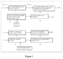
- the method includes an initial synchronization phase and a continuous synchronization phase.
- Te is 1 ⁇ 4 microsecond and we has four samples for a received symbol.
- the previously described steps aim to identify a known pattern from the samples (which have undergone the transformation) and thus achieve the time synchronization.
- the cumulation parameter "NRep” varies depending on the reception conditions. In the case where the conditions of reception are good, “NRep” is worth 0 because it is not necessary to make a cumulation to obtain the beginning of the frame. Even at low SNR, the peak can be detected, but the principle of accumulation of values makes the peak detection reliable. This does not mean, however, that the first peak detected is not the right one.
- the continuous synchronization phase comprises substantially the same steps as those of the initial synchronization, with the difference that it is not necessary to accumulate the quantities R as many times as for the initial synchronization.
- the number of accumulations "NRep” is then replaced by a lower value "NDmotif".
- quantities R are examined: these are the quantities that are located substantially at the sampling instants, that is to say at the time of sampling or just before or just after.
- the invention relates to a method adapted in particular to a transmission frame consisting of pilot fields and information symbol fields.
- the frame is defined by the communication standard and the invention does not change the definition of this frame. Indeed, the time synchronization is carried out at the reception of the signal and the frames have already been composed by the transmitter according to the broadcast standard implemented.
- the frame can be seen by a regular succession or not of pilot fields and information fields.
- the regularity of the succession makes the plot more optimum.
- the information data are of lengths I interspersed by the pilot sequences of length P.
- the N pilot sequences are repeated regularly at course of time.
- a synchronization pilot sequence can be multiplied symbol by symbol by a predetermined sequence of length preferably N * P in order to obtain a sequence of pilot symbols with good intercorrelation properties.
- the method of the invention realizes a transformation on the symbols received at the rate Te after an oversampling has been performed on the received symbols.
- the transformation consists of a multiplication of the received symbol r (nTe) at the rate Te current by the conjugate the symbol delayed by an integer of Ts , preferably Ts, to obtain a new sequence of symbols X () at the rate Te.
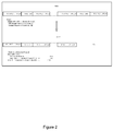
- the invention defines the construction of a pattern used at the receiver. This reason is built from the definition of the issuer. An example of such a pattern is presented in relation to the figure 2 .
- the pattern preferably begins at the position corresponding to the first symbol of the first synchronization pilot sequence (i.e., the pattern starts at the first symbol of P1).
- the symbol of the pattern is constructed by applying the same transformation applied to the received signal (transformation step of the method of the invention, see 7.2.2).
- the complex number resulting from the transformation is equal to the product of the pilot symbol by the conjugate of the preceding symbol of the synchronization pilot sequence. If the preceding symbol is an information symbol, in this situation, the symbol of the pattern is preferably "0". On the positions corresponding to the data field, the symbols of the pattern are preferably null values.
- this pattern has good cross-correlation properties.
- we present in relation to the figure 3 the cross-correlation function of the pattern when the synchronization pilot sequence complex is constructed from a gold sequence of length 2 18 -1 (as previously presented).
- the method comprises a so-called initial time synchronization phase, and a so-called time synchronization phase followed.
- the method makes it possible to correct the selected sample instant in a progressive manner by taking a sample close to the current sample chosen.
- the method of the invention can be implemented behind a digital reception filter when the ratio between the frequency deviation accepted at the receiver, due to the offset between the transceiver oscillators and the offset caused by the maximum Doppler, and the bandwidth of the transmitted signal is less than 1/10. This is generally the case for signal bands between 5 MHz and 8 MHz, at carrier frequencies of about 2 GHz.
- the frequency matching algorithm can then take advantage of the output information from the time synchronization method of the invention and in particular the position of the start of the pattern. It is then possible to use a frequency synchronization algorithm that will use the data derived from the maximum likelihood criterion.
- the method of the invention can be implemented upstream of a coarse frequency estimation module when the frequency offset is of the order of the bandwidth of the transmitted signal. if not, more.
Abstract
Description
La présente invention se rapporte au domaine de la synchronisation de signaux de données numériques.The present invention relates to the field of synchronization of digital data signals.
Plus particulièrement, la présente invention concerne un procédé permettant la synchronisation temporelle et la détection de début de blocs temporels pour des transmissions par trame.More particularly, the present invention relates to a method for time synchronization and start detection of time blocks for frame transmissions.
Le procédé de l'invention peut notamment être mis en oeuvre lors de transmissions par trames ou paquets pour des applications de télécommunication et de diffusion par satellite et par des liaisons faisceaux hertziens ou des liaisons radio fixes ou mobiles.The method of the invention may in particular be implemented during transmission by frames or packets for telecommunication and satellite broadcasting applications and by radio-relay links or fixed or mobile radio links.
La synchronisation temporelle ou la détection de début de trame dans un signal est un point délicat de la transmission de données en mode trame ou paquet, surtout pour les nouvelles applications de communications multimédia à débit élevé. Ainsi, l'opération de synchronisation temporelle doit pouvoir fonctionner dans des conditions de plus en plus difficiles en terme notamment de puissance du signal reçue, et de précision de calage fréquentiel de la fréquence porteuse.Time synchronization or start-of-frame detection in a signal is a delicate point in frame or packet mode data transmission, especially for new high-speed multimedia communications applications. Thus, the time synchronization operation must be able to operate under conditions that are increasingly difficult in terms, in particular, of the power of the signal received, and the accuracy of the frequency setting of the carrier frequency.
De plus, en règle générale, l'opération de synchronisation temporelle d'un signal prend place après une opération de synchronisation fréquentielle grossière. Ces deux opérations se rebouclent l'une avec l'autre, apportant par voie de conséquence un temps de synchronisation assez élevé et donc pénalisant pour des applications demandant des temps de réaction très brefs.In addition, as a general rule, the temporal synchronization operation of a signal takes place after a coarse frequency synchronization operation. These two operations are looping with each other, bringing consequently a relatively high synchronization time and therefore penalizing for applications requiring very short reaction times.
Les nouveaux standards de diffusion ou de télécommunication par exemple, incorporent des constellations QPSK (de l'anglais « Quadrature Phase Shift Keying »), mais aussi de dimensions plus élevées : 8 PSK, 16 PSK, 16 APSK, 32 APSK, pour augmenter le nombre d'informations utiles transmises, avec des codes correcteurs d'erreurs turbo, exigeant ainsi de la part du récepteur de fonctionner en réception cohérente, à des points de fonctionnement faibles, c'est-à-dire à des rapports signal à bruit SNR (de l'anglais « Signal to Noise Ratio ») faibles. De tels rapport SNR se situent à des niveaux de l'ordre de SNR=-3 dB pour une constellation QPSK, SNR=5 dB pour une 8 PSK, avec des décalages fréquentiels liés à la désynchronisation entre les oscillateurs locaux et le Doppler créés par des communications mobiles.New broadcast or telecommunication standards, for example, incorporate QPSK (Quadrature Phase Shift Keying) constellations, but also higher dimensions: 8 PSK, 16 PSK, 16 APSK, 32 APSK, to increase number of useful information transmitted, with turbo error correcting codes, thus requiring the receiver to operate in coherent reception, at low operating points, that is, signal to noise (SNR) ratios of the signal to noise ratio. Such SNR ratios are at levels of the order of SNR = -3 dB for a QPSK constellation, SNR = 5 dB for a PSK, with frequency shifts related to the desynchronization between the local oscillators and the Doppler created by mobile communications.
Ces mêmes standards permettent de plus l'émission de différents programmes répartis temporellement dans le signal et demandant au récepteur qui souhaite les mettre en oeuvre de basculer rapidement d'un programme à un autre.These same standards allow moreover the emission of different programs temporally distributed in the signal and asking the receiver who wishes to implement them to quickly switch from one program to another.
Il donc nécessaire d'avoir des temps de synchronisation très rapides lorsque le récepteur bascule d'un programme à un autre, et ce même dans des conditions de point de fonctionnement faibles.It is therefore necessary to have very fast synchronization times when the receiver switches from one program to another, even under low operating point conditions.
Pour accélérer la synchronisation, ces nouveaux standards utilisent des communications par trame comprenant des symboles connus dits pilotes. Des algorithmes de synchronisation sont alors mis en oeuvre au sein du récepteur en se basant sur le principe du critère du maximum de vraisemblance pour repérer les symboles pilotes et accélérer la synchronisation.To speed up synchronization, these new standards use frame communications comprising known symbols known as pilots. Synchronization algorithms are then implemented within the receiver based on the principle of the maximum likelihood criterion to identify pilot symbols and accelerate synchronization.
Les trames émises à destination des récepteurs sont alors construites en insérant une ou plusieurs séquences pilotes entre des données, puis en répétant ces séquences avec une règle de périodicité connue. La ou les séquences pilotes sont connues du récepteur puisqu'elles sont définies par le standard lui même.The frames sent to the receivers are then constructed by inserting one or more pilot sequences between data, and then repeating these sequences with a rule of known periodicity. The pilot sequence (s) are known to the receiver since they are defined by the standard itself.
Les séquences connues ont de bonnes propriétés d'intercorrélation, notamment un nombre de pics secondaires limités permettant de se décider sans se tromper. Elles peuvent être construites par exemple en multipliant chaque symbole complexe connu fixé par un symbole déduit d'une séquence complexe aléatoire crée à partir d'une séquence de « Gold ».The known sequences have good cross-correlation properties, in particular a limited number of secondary peaks making it possible to decide without being mistaken. They can be constructed for example by multiplying each known complex symbol fixed by a symbol deduced from a random complex sequence created from a sequence of "Gold".
Comme cela a déjà été évoqué, il est de plus en plus important de pouvoir réaliser une synchronisation ou une détection de blocs rapide à des points de fonctionnement faibles en termes de rapport signal à bruit SNR, même dans le cas de mobilité (par exemple réception multimédia dans un véhicule). Ces besoins s'expriment tant en transmission par satellite qu'en transmission par l'intermédiaire de faisceaux hertziens ou de liaison radios.As has already been mentioned, it is increasingly important to be able to synchronize or detect fast blocks at points of interest. operation in terms of SNR signal-to-noise ratio, even in the case of mobility (eg multimedia reception in a vehicle). These needs are expressed in both satellite transmission and transmission via radio links or radio links.
Ainsi, par exemple, en satellite, un récepteur doit pouvoir fonctionner autour d'un SNR=-3 dB pour des communications par paquets avec une constellation QPSK.Thus, for example, in satellite, a receiver must be able to operate around an SNR = -3 dB for packet communications with a QPSK constellation.
Pour faciliter ce fonctionnement à des SNR faibles, une solution communément admise est de choisir une communication par trames avec une ou plusieurs séquences pilotes connues et répétées pour diminuer le temps de convergence et à la synchronisation temporelle à faible rapport signal à bruit. Ces techniques dites PA (de l'anglais «Pilot Aided » pour «Aidée par Pilotage ») se différentient des techniques à l'aveugle NDA (Non Data Aided).To facilitate this operation at low SNRs, a commonly accepted solution is to choose a frame communication with one or more known and repeated pilot sequences to reduce convergence time and time synchronization at low signal-to-noise ratio. These so-called "Pilot Aided" (PA) techniques are different from the NDA (Non Data Aided) techniques.
Pour les techniques dites à l'aveugle, par exemple pour les applications satellite, l'algorithme de Gardner et l'algorithme de Meyr sont utilisés. L'algorithme de Gardner utilise les passages à zéros du signal reçu tandis que l'algorithme de Meyr récupère l'écart temporel en créant une non linéarité qui apporte un signal périodique fournissant l'information d'écart temporel.For so-called blind techniques, for example for satellite applications, Gardner's algorithm and Meyr's algorithm are used. Gardner's algorithm uses the zero-passes of the received signal while Meyr's algorithm retrieves the time gap by creating a nonlinearity that provides a periodic signal providing the time gap information.
De tels algorithmes fonctionnent toujours en association avec des algorithmes de calage fréquentiels, la précision de l'algorithme fréquentiel impactant directement sur le fonctionnement et la précision de l'algorithme de synchronisation temporelle. Dans la plupart des cas, notamment pour des communications multimédia par satellite, un rebouclage entre les deux algorithmes est mis en oeuvre pour avoir au bout d'un certain temps une convergence suffisante qui permet de prendre une décision sur le calage temporel et sur le calage fréquentiel.Such algorithms always work in association with frequency matching algorithms, the accuracy of the frequency algorithm directly impacting the operation and accuracy of the time synchronization algorithm. In most cases, in particular for multimedia communications by satellite, a looping between the two algorithms is implemented to have, after a certain time, a sufficient convergence which makes it possible to take a decision on timing and timing frequency.
Les techniques PA utilisent des séquences pilotes connues mises dans la trame. L'algorithme utilisé au niveau du récepteur est un algorithme qui fait une estimation au sens du maximum de vraisemblance de la séquence du motif de référence recherché.PA techniques use known pilot sequences in the frame. The algorithm used at the receiver is an algorithm that makes a estimation in the sense of maximum likelihood of the sequence of the desired reference pattern.
Ces techniques permettent au récepteur de diminuer son temps d'accrochage, et de travailler à plus faible rapport signal à bruit lorsque le nombre de symboles dans le motif est suffisant, et lorsque la répétition des séquences pilotes est convenablement choisie pour l'application visée de part le canal de propagation que subira le signal émis.These techniques allow the receiver to decrease its latching time, and work at a lower signal-to-noise ratio when the number of symbols in the pattern is sufficient, and when the repetition of the pilot sequences is suitably chosen for the intended application of part of the propagation channel that the transmitted signal will undergo.
Des techniques PA sont utilisées pour de la synchronisation temporelle dans les systèmes de radio cellulaire comme le GSM ou le WiMax. Elles travaillent avec des symboles connus regroupés selon une certaine règle qui définissent une séquence connue avec de bonnes propriétés d'intercorrélation, celle-ci est émise et répétée suivant un certain rythme. Pour ces applications, une synchronisation fréquentielle est effectuée en premier lieu grâce à une trame particulière « FCH » (de l'anglais « Fréquency Correction Channel » pour « Canal de Corrélation Fréquentiel ») qui dans le principe envoie une fréquence pure, puis une synchronisation temporelle est réalisée grâce à une trame particulière dite « SCH ».PA techniques are used for time synchronization in cellular radio systems such as GSM or WiMax. They work with known symbols grouped according to a certain rule which define a known sequence with good intercorrelation properties, this one is emitted and repeated according to a certain rhythm. For these applications, a frequency synchronization is performed firstly by means of a particular frame "FCH" (of the English "Frequency Correction Channel" for "Frequency Correlation Channel") which in principle sends a pure frequency, then a synchronization time is achieved through a special frame called "SCH".
D'autres techniques PA sont aussi utilisées dans des standards comme dans le DVB S2 ou le DVB SH mode TDM. Pour le standard DVB S2, une séquence de pilotes est répétée afin de faciliter l'estimation de la phase. Cette séquence est codée différentielle à l'émetteur. Ce n'est pas le cas pour le standard DVB SH. Pour le DVB SH la trame a deux séquences pilotes qui se répartissent régulièrement entre des blocs de données. Ces séquences sont plus longues que dans le cas DVB S2 et ne sont pas codées différentiellement à l'émetteur.Other PA techniques are also used in standards such as DVB S2 or DVB SH TDM mode. For the DVB S2 standard, a sequence of pilots is repeated to facilitate the estimation of the phase. This sequence is coded differential to the transmitter. This is not the case for the DVB SH standard. For the DVB SH the frame has two pilot sequences which are distributed regularly between blocks of data. These sequences are longer than in the case DVB S2 and are not coded differentially to the transmitter.
Ces dernières techniques PA, utilisent des séquences pilotes avec de bonnes propriétés d'intercorrélation, c'est-à-dire avec des pics secondaires peu importants. Elles appartiennent aux techniques PA qui travaillent à partir de trames reçues comprenant des données entrecoupées de séquences pilotes définies par le standard et répétées temporellement périodiquement ou non.The latter techniques PA, use pilot sequences with good cross-correlation properties, that is to say with minor secondary peaks. They belong to the PA techniques that work from received frames comprising data interspersed with pilot sequences defined by the standard and repeated temporally periodically or not.
Par exemple, dans le standard DVB SH mode TDM, les deux séquences pilotes complexe répétées sont construites à partir d'une séquence binaire complexe déduite d'une séquence de Gold avec une fonction d'intercorrélation avec un pic principal très prononcé, et des pics secondaires au nombre faible, et très atténués.For example, in the DVB SH mode TDM standard, the two repeated complex pilot sequences are constructed from a complex binary sequence derived from a Gold sequence with a cross-correlation function with a very pronounced principal peak, and peaks secondary to the low number, and very attenuated.
Les techniques à l'aveugle et les techniques PA présentent des inconvénients.Blind techniques and PA techniques have disadvantages.
Par exemple, l'algorithme de Gardner utilisé dans les techniques à l'aveugle fonctionne bien pour un rapport signal à bruit raisonnable mais nécessite un temps d'acquisition important et, de la même façon que l'algorithme de Meyr, est sensible aux décalages fréquentiels. Aussi ces derniers algorithmes nécessitent une synchronisation fréquentielle grossière en aval.For example, the Gardner algorithm used in blind techniques works well for a reasonable signal-to-noise ratio but requires a significant acquisition time and, in the same way as the Meyr algorithm, is sensitive to offsets. frequency. Also these last algorithms require a coarse frequency synchronization downstream.
Un rebouclage entre ces deux dernières opérations (synchronisation temporelle et synchronisation fréquentielle) est couramment réalisé et demande un temps de convergence, donc un temps d'acquisition assez élevé. De plus, il est d'autant plus élevé que le rapport signal à bruit devient négatif. Ce temps devient donc trop important pour certaines applications.A loopback between these last two operations (time synchronization and frequency synchronization) is commonly performed and requires a convergence time, so a fairly high acquisition time. In addition, it is even higher than the signal-to-noise ratio becomes negative. This time becomes too important for some applications.
De plus, l'algorithme de Gardner et l'algorithme de Meyr étant à l'aveugle, ils ne peuvent donc apporter aucune information sur la trame, notamment le début d'un bloc répétitif de la trame comme par exemple le début de la séquence pilote de synchronisation connue.In addition, since Gardner's algorithm and Meyr's algorithm are blind, they can not provide any information on the frame, especially the beginning of a repetitive block of the frame, for example the beginning of the sequence. known synchronization driver.
D'une manière générale, les techniques à l'aveugle ne permettent pas d'apporter des informations quant à la trame, notamment le début d'un bloc répétitif de la trame comme par exemple le début de la séquence pilote de synchronisation connue.In general, the blind techniques do not provide information about the frame, including the beginning of a repetitive block of the frame such as the beginning of the known synchronization pilot sequence.
Les techniques PA présentent elles aussi des inconvénients. En effet, dans ces techniques PA, utilisée par exemple GSM ou WiMax, une séquence connue (pilote) est émise sur une trame particulière. Le récepteur utilise alors une technique PA.PA techniques also have disadvantages. In fact, in these PA techniques, used for example GSM or WiMax, a known (pilot) sequence is transmitted on a particular frame. The receiver then uses a PA technique.
Un module de calage fréquentiel aidé par une trame réservée sur le canal de synchronisation (« SCH », de l'anglais « Synchronization Channel ») est nécessaire en aval puisque l'algorithme n'arrive à fonctionner qu'avec un écart fréquentiel inférieur environ à 10-3/Ts, avec « Ts » étant la fréquence de réception des symboles du signal, un ensemble de symboles formant une trame. Les techniques PA nécessitent donc la mise en oeuvre d'un calage fréquentiel supplémentaire, ce qui n'est pas pratique.A frequency blocking module assisted by a frame reserved on the Synchronization Channel ("SCH") is necessary downstream since the algorithm can operate only with a lower frequency difference approximately 10- 3 / Ts, with "Ts" is the frequency of reception of the symbols of the signal, a set of symbols forming a frame. PA techniques therefore require the implementation of additional frequency calibration, which is not practical.
L'objectif de l'invention est de permettre une synchronisation temporelle rapide. Un autre objet de l'invention est de réaliser rapidement une acquisition des débuts des trames. Un autre objet de l'invention est de permettre la synchronisation et l'acquisition à un point de fonctionnement très faible en terme de rapport signal à bruit, par exemple de l'ordre de -3dB.The objective of the invention is to allow rapid temporal synchronization. Another object of the invention is to rapidly achieve an acquisition of the beginnings of the frames. Another object of the invention is to allow synchronization and acquisition at a very low operating point in terms of signal-to-noise ratio, for example of the order of -3 dB.
Un autre objet de l'invention est de disposer d'un procédé de synchronisation temporelle qui ne dépende pas de la précision d'un procédé de synchronisation fréquentielle.Another object of the invention is to provide a temporal synchronization method which does not depend on the accuracy of a frequency synchronization method.
L'invention ne présente pas les inconvénients de l'art antérieur. En effet, l'invention concerne un procédé de synchronisation temporelle d'un signal numérique dans un système de communication par trames, chacune desdites trames comprenant des symboles d'information et au moins deux séquences de symboles de pilotes de synchronisation périodique.The invention does not have the drawbacks of the prior art. Indeed, the invention relates to a time synchronization method of a digital signal in a frame communication system, each of said frames comprising information symbols and at least two periodic synchronization pilot symbol sequences.
Selon l'invention, un tel procédé comprend une phase de synchronisation comprenant les étapes suivantes :
- suréchantillonnage d'un signal reçu, suivant un facteur de suréchantillonage K, délivrant K échantillons de durée Te pour un temps symbole Ts ;
- obtention d'une information de sélection pour chaque échantillon, à l'aide d'une fonction prédéterminée X() tenant compte dudit échantillon et d'au moins un échantillon reçu précédemment ;
- comparaison desdites informations de sélection avec un motif de référence connu Mo et
- sélection de l'instant d'échantillonnage d'un desdits échantillons comme point de synchronisation, en fonction des résultats desdites comparaisons ;
- oversampling of a received signal, according to an oversampling factor K , delivering K samples of duration Te for a symbol time Ts ;
- obtaining a selection information for each sample, using a predetermined function X () taking into account said sample and at least one previously received sample;
- comparing said selection information with a known reference pattern Mo and
- selecting the sampling instant of one of said samples as synchronization point, according to the results of said comparisons;
Ainsi l'invention propose une méthode de synchronisation temporelle pour des communications par trame ou paquet qui fonctionne à faible rapport signal à bruit, qui résiste aux décalages fréquentiels, et a un comportement régulier pour tout décalage fréquentiel, et est donc bien adapté aux applications avec mobilité, (c'est-à-dire avec du Doppler, avec des signaux à des débits suffisamment élevés).Thus the invention proposes a time synchronization method for frame or packet communications which operates at low signal-to-noise ratio, which resists frequency offsets, and has a regular behavior for any frequency offset, and is therefore well adapted to applications with mobility, (that is, with Doppler, with signals at sufficiently high rates).
Un tel résultat est obtenu, selon l'invention, en combinant l'utilisation de deux séquences de symboles pilote de synchronisation qui sont présentes dans une trame et la comparaison d'information de sélection obtenues à partir de ces séquences de symboles pilote transformées avec un motif de référence connu.Such a result is obtained, according to the invention, by combining the use of two sequences of synchronization pilot symbols which are present in a frame and the comparison of selection information obtained from these pilot symbol sequences transformed with a known reference pattern.
L'invention permet également de détecter en même temps que l'instant d'échantillonnage pour la synchronisation, les débuts des séquences pilotes répétées temporellement même en présence de forts décalages fréquentiels car la séquence se suffit à elle-même pour se synchroniser. Ainsi, un décalage de fréquence n'a pas d'effet.The invention also makes it possible to detect at the same time as the sampling instant for the synchronization, the beginnings of the pilot sequences repeated temporally even in the presence of strong frequency offsets because the sequence is self-sufficient to synchronize itself. Thus, a frequency offset has no effect.
L'invention permet également d'éviter un rebouclage entre les algorithmes de synchronisation fréquentielle et de synchronisation temporelle pour des applications avec des bandes passantes largement plus élevées que le Doppler, et donc permet des temps d'acquisition très faibles.The invention also makes it possible to avoid a loopback between frequency synchronization and time synchronization algorithms for applications with much higher bandwidths than Doppler, and thus allows very low acquisition times.
L'invention permet encore une grande souplesse sur le choix de l'architecture du récepteur, puisqu'elle évite dans certaines situations un module de synchronisation fréquentielle en aval d'un module de synchronisation temporelle, et ainsi permet de placer un module de synchronisation fréquentielle en amont du module de synchronisation temporelle.The invention still allows great flexibility in the choice of the architecture of the receiver, since it avoids in certain situations a frequency synchronization module downstream of a synchronization module temporal, and thus makes it possible to place a frequency synchronization module upstream of the temporal synchronization module.
L'invention permet également d'avoir une rapidité de réponse de la synchronisation temporelle.The invention also makes it possible to have a speed of response of the temporal synchronization.
Selon une caractéristique particulière de l'invention, pour chaque échantillon :
- ladite fonction prédéterminée X() comprend une étape de multiplication dudit échantillon par le conjugué d'un échantillon précédent, délivrant un échantillon transformé ;
- ladite étape de comparaison comprend une étape de calcul d'une corrélation entre ledit échantillon transformé et ledit motif préalablement connu Mo.
- said predetermined function X () comprises a step of multiplying said sample by the conjugate of a preceding sample, delivering a transformed sample;
- said comparing step comprises a step of calculating a correlation between said processed sample and said previously known Mo ground.
Selon un mode de réalisation particulier de l'invention, ladite phase de synchronisation comprend en outre une étape de cumul de desdites corrélations correspondant à au moins deux temps symbole successifs, au sein d'une structure de données de cumul de corrélation stockant des quantités RT de corrélations cumulées pour chaque échantillon, et en ce que ladite étape de sélection tient compte desdites quantités RT.According to a particular embodiment of the invention, said synchronization phase further comprises a step of aggregating said correlations corresponding to at least two successive symbol times, within a correlation accumulation data structure storing RT quantities. cumulative correlations for each sample, and in that said selecting step takes said RT amounts into account.
Selon une caractéristique particulière de l'invention, pour chaque échantillon à un temps d'échantillonnage Te ladite fonction prédéterminée X() vaut : ![]()
où :
- r(nTe) est le nième échantillon reçu au temps Te ;
- r(nTe-xTs) est le nième échantillon reçu au temps Te retardé d'une valeur entière x fois le temps Ts.
or :
- r (nTe) is the nth sample received at time Te ;
- r (nTe-xTs) is the nth sample received at the time Te delayed by an integer value x times the time Ts.
Selon une caractéristique particulière de l'invention, ladite valeur de retard x vaut 1.According to one particular characteristic of the invention, said delay value x is equal to 1.
Selon un mode de réalisation particulier de l'invention, pour un échantillon donné, ladite corrélation est une enveloppe de corrélation d'un nombre complexe.According to a particular embodiment of the invention, for a given sample, said correlation is a correlation envelope of one complex number.
Ainsi, le calcul de l'enveloppe de corrélation peut être réalisé à l'aide de la fonction générale suivante : 
dans laquelle :
- i varie de 0 à K-1 ;
- j varie de 0 à P1+I1+P2+....Pn-1 et dans lequel :
- Le premier champ pilote est de longueur P1 ;
- Le deuxième champ pilote est de longueur P2 ;
- Le troisième champ pilote est de longueur P3 ;
- Le premier champ d'information entre le premier champ pilote et le second est de longueur I1 ;
- Le deuxième champ d'information entre le deuxième champ pilote et le troisième est de longueur I2 ;
- etc.
in which :
- i varies from 0 to K-1;
- j varies from 0 to P1 + I1 + P2 + .... Pn-1 and wherein:
- The first pilot field is of length P1;
- The second pilot field is of length P2;
- The third pilot field is of length P3;
- The first information field between the first pilot field and the second one is of length I1;
- The second information field between the second pilot field and the third field is of length I2;
- etc.
Selon cette précédente fonction, le motif Mo est étalé sur ![]()
![]()
De manière plus précise, lorsque P1 et P2 ont une longueur de 80 symboles et I1 à une longueur de 1008 symboles, la trame comprend un champ P1 puis un champ I1 puis un champ P2 puis un champ I2 alors la fonction de calcul de l'enveloppe de corrélation est la suivante : 
Selon un mode de réalisation particulier de l'invention, ledit procédé comprend en outre une phase de contrôle de synchronisation en continu par estimation en utilisant lesdits symboles d'information et ledit instant d'échantillonnage préalablement déterminé.According to a particular embodiment of the invention, said method further comprises a continuous synchronization control phase by estimation using said information symbols and said previously determined sampling time.
Selon une caractéristique particulière de l'invention, ladite phase de contrôle de synchronisation par estimation comprend les étapes suivantes :
- suréchantillonnage d'un signal reçu, suivant un facteur de suréchantillonage K, délivrant au moins deux échantillons à un temps d'échantillonnage Te pour une durée correspondant à un temps symbole Ts ;
- obtention d'une information de sélection pour chaque échantillon, à l'aide d'une fonction prédéterminée X() tenant compte dudit échantillon et d'au moins un échantillon reçu précédemment ;
- comparaison desdites informations de sélection avec un motif de référence connu Mo et
- sélection de l'instant d'échantillonnage d'un desdits échantillons comme point de synchronisation, en fonction des résultats desdites comparaisons et dudit instant d'échantillonnage préalablement déterminé.
- oversampling of a received signal, according to a factor of oversampling K, delivering at least two samples at a sampling time Te for a period corresponding to one symbol time Ts;
- obtaining a selection information for each sample, using a predetermined function X () taking into account said sample and at least one previously received sample;
- comparing said selection information with a known reference pattern Mo and
- selecting the sampling instant of one of said samples as synchronization point, as a function of the results of said comparisons and of said previously determined sampling time.
Ainsi, l'invention permet de réduire le temps nécessaire au suivi de la synchronisation. En effet, plutôt que de calculer de multiples corrélations, l'invention permet de ne calculer que les corrélations qui se situent autour d'un point de la séquence de symbole qui correspondre au point de synchronisation préalablement déterminé lors de la synchronisation initiale et non pas de recommencer tous les calculs pour s'assurer du maintien de la synchronisation.Thus, the invention makes it possible to reduce the time necessary to monitor the synchronization. Indeed, rather than calculating multiple correlations, the invention makes it possible to calculate only the correlations which are situated around a point of the symbol sequence which corresponds to the synchronization point previously determined during the initial synchronization and not to repeat all calculations to ensure that synchronization is maintained.
L'invention concerne également un signal numérique destiné à être émis par au moins un émetteur et reçu par au moins un récepteur mettant en oeuvre le procédé de synchronisation tel que décrit précédemment, dans un système de communication par trames, chacune desdites trames comprenant des symboles d'information et au moins deux séquences de symboles pilotes de synchronisation P0 et P1.The invention also relates to a digital signal intended to be transmitted by at least one transmitter and received by at least one receiver implementing the synchronization method as described above, in a frame communication system, each of said frames comprising symbols. of information and at least two sequences of pilot synchronization symbols P0 and P1.
Selon l'invention, un dans un tel signal lesdites séquences de symboles pilotes de synchronisation P0 et P1 sont choisies de façon qu'elles maximisent un résultat d'un calcul de corrélation entre des échantillons desdits symboles de pilotes et un motif de référence connu Mo à l'aide d'une fonction prédéterminée.According to the invention, in one such signal, said synchronous pilot symbol sequences P0 and P1 are chosen so that they maximize a result of a correlation calculation between samples of said pilot symbols and a known reference pattern Mo using a predetermined function.
L'invention concerne également un procédé de construction d'un signal numérique tel que décrit précédemment, dans un système de communication par trames, chacune desdites trames comprenant des symboles d'information et au moins deux séquences de symboles de pilotes de synchronisation P0 et P1,The invention also relates to a method for constructing a digital signal as described above, in a frame communication system, each of said frames comprising information symbols and to minus two synchronous pilot symbol sequences P0 and P1 ,
Selon l'invention, un tel procédé de construction comprend une étape de détermination desdites séquences de symboles pilotes de synchronisation P0 et P1 de façon qu'elles maximisent un résultat d'un calcul de corrélation entre des échantillons desdits symboles de pilotes et un motif de référence connu Mo à l'aide d'une fonction prédéterminée.According to the invention, such a construction method comprises a step of determining said synchronization pilot symbol sequences P0 and P1 so that they maximize a result of a correlation calculation between samples of said pilot symbols and a pattern of known reference Mo using a predetermined function.
Selon une caractéristique particulière de l'invention, caractérisé en ce que ladite étape de détermination met en oeuvre le calcul suivant : ![]()
![]()
dans lequel :
- « P » est le nombre de symboles qui composent respectivement les symboles P0 et P1 ;
- « I » est le nombre de symboles de données d'information d'une trame ;
- « Cn » est le nième symbole complexe d'une séquence déduite d'une séquence de Gold de longueur 218-1 ;
- « j » étant la notation imaginaire d'un nombre complexe.
in which :
- "P" is the number of symbols that respectively make up the symbols P0 and P1 ;
- "I" is the number of information data symbols of a frame;
- " Cn " is the n th complex symbol of a sequence deduced from a Gold sequence of length 2 18 -1;
- "J" being the imaginary notation of a complex number.
L'invention concerne également un dispositif de synchronisation temporelle d'un signal numérique dans un système de communication par trames, chacune desdites trames comprenant des symboles d'information et au moins deux séquences de symboles de pilotes de synchronisation.The invention also relates to a time synchronization device of a digital signal in a frame communication system, each of said frames comprising information symbols and at least two synchronization pilot symbol sequences.
Selon l'invention, un tel dispositif comprend des moyens de synchronisation comprenant des moyens de :
- suréchantillonnage d'un signal reçu, suivant un facteur de suréchantillonage K, délivrant au moins deux échantillons à un temps d'échantillonnage Te pour une durée correspondant à un temps symbole Ts ;
- obtention d'une information de sélection pour chaque échantillon, à l'aide d'une fonction prédéterminée X() tenant compte dudit échantillon et d'au moins un échantillon reçu précédemment ;
- comparaison desdites informations de sélection avec un motif de référence connu Mo et
- sélection de l'instant d'échantillonnage d'un desdits échantillons comme point de synchronisation, en fonction des résultats desdites comparaisons.
- oversampling of a received signal, according to an oversampling factor K , delivering at least two samples at a sampling time Te for a duration corresponding to a symbol time Ts ;
- obtaining a selection information for each sample, using a predetermined function X () taking into account said sample and at least one previously received sample;
- comparing said selection information with a known reference pattern Mo and
- selecting the sampling instant of one of said samples as synchronization point, according to the results of said comparisons.
Selon un autre aspect, l'invention concerne également un produit programme d'ordinateur téléchargeable depuis un réseau de communication et/ou stocké sur un support lisible par ordinateur et/ou exécutable par un microprocesseur, et comprenant des instructions de code de programme pour l'exécution du procédé de synchronisation tel que décrit précédemment.According to another aspect, the invention also relates to a computer program product downloadable from a communication network and / or stored on a computer-readable medium and / or executable by a microprocessor, and comprising program code instructions for the computer. execution of the synchronization method as described above.
D'autres caractéristiques et avantages de l'invention apparaîtront plus clairement à la lecture de la description suivante d'un mode de réalisation préférentiel, donné à titre de simple exemple illustratif et non limitatif, et des dessins annexés, parmi lesquels :
- la
figure 1 présente un synoptique du procédé de l'invention ; - la
figure 2 présente le principe de construction d'un motif Mo ; - la
figure 3 présente l'intercorrélation du motif en fonction du retard ; - la
figure 4 est un exemple de définition de trame.
- the
figure 1 presents a block diagram of the method of the invention; - the
figure 2 presents the principle of construction of a Mo pattern; - the
figure 3 presents the intercorrelation of the pattern as a function of the delay; - the
figure 4 is an example of a frame definition.
- Ts : fréquence de réception des symboles du signal ;Ts: frequency of reception of the symbols of the signal;
- Trame : elle est constituée d'une suite de symboles d'informations entrecoupée de séquences de pilotes de synchronisation réparties périodiquement ;Frame: it consists of a sequence of information symbols interspersed with periodically distributed synchronization driver sequences;
- Séquences de pilotes de synchronisation : elles sont connues lors de la mise en oeuvre du procédé de l'invention car elles font parties de la norme mis en oeuvre. La séquence est composée d'une suite de symboles connus ;Sequences of synchronization drivers: they are known during the implementation of the method of the invention because they are part of the standard implemented. The sequence is composed of a series of known symbols;
L'invention propose de réaliser une synchronisation temporelle qui ne nécessite pas obligatoirement de synchronisation fréquentielle préalable et qui diminue le temps nécessaire au traitement sous la forme d'un procédé de synchronisation temporel qui effectue des transformations et des calculs sur les séquences de symboles reçues. Le procédé de synchronisation temporel proposé par l'invention permet de synchroniser temporellement un récepteur en supportant des écarts fréquentiels élevés quelconque et ceci même à très faible rapport signal à bruit (RSB ou SNR) dans un système de communications par trame constituée d'une suite de symboles d'informations entrecoupées de séquences pilotes réparties périodiquement. Le procédé de l'invention est particulièrement adapté à la mise en oeuvre d'applications temps réel exigeantes, le tout en conditions de mobilité.The invention proposes to carry out a time synchronization which does not necessarily require prior frequency synchronization and which reduces the time required for the processing in the form of a time synchronization method which performs transformations and calculations on the received symbol sequences. The temporal synchronization method proposed by the invention makes it possible to synchronize a receiver temporally by supporting any high frequency deviations and this even at a very low signal-to-noise ratio (SNR or SNR) in a frame-based communications system consisting of a sequence information symbols interspersed with periodically distributed pilot sequences. The method of the invention is particularly adapted to the implementation of demanding real-time applications, all in mobility conditions.
L'invention concerne également un dispositif qui comprend des moyens de mise en oeuvre de la synchronisation temporelle selon l'invention.The invention also relates to a device that comprises means for implementing the time synchronization according to the invention.
Le principe général de l'invention repose sur l'utilisation d'une ou plusieurs hypothèses temporelles préalables et sur l'utilisation d'une information sur la présence périodique d'un motif connu au préalable du récepteur et qui possède de bonnes propriétés de corrélation.The general principle of the invention is based on the use of one or more prior temporal hypotheses and on the use of information on the periodic presence of a pattern previously known to the receiver and which has good correlation properties. .
L'invention concerne également, à part entière, ce motif qui possède de bonnes propriétés de corrélation de part sa construction directement déduite des travaux réalisés par les inventeurs. En effet, ce motif particulier selon l'invention possède de bonnes propriétés d'intercorrélation, avec en particulier une fonction d'intercorrélation qui comporte peu de pics secondaires.The invention also relates, in its own right, to this pattern which has good correlation properties because of its construction directly deduced from the work carried out by the inventors. Indeed, this particular pattern according to the invention has good cross-correlation properties, with in particular a cross-correlation function which has few secondary peaks.
Le principe de l'invention consiste ainsi à rechercher des instants d'échantillonage à partir d'une transformation qui est appliquée à des symboles reçus et des calculs de corrélation avec un motif préalablement constitué.The principle of the invention thus consists in searching for sampling instants from a transformation that is applied to received symbols and correlation calculations with a previously constituted pattern.
L'invention permet d'obtenir un temps d'acquisition et de synchronisation très faible, fonctionnant à des rapports signal à bruit négatifs, sans besoin de travailler en association avec un algorithme de synchronisation fréquentielle pour certaines applications comme des applications satellite multimédia.The invention makes it possible to obtain a very low acquisition and synchronization time, operating at negative signal-to-noise ratios, without having to work in association with a synchronization algorithm. frequency for some applications such as satellite multimedia applications.
De plus, l'invention permet de déterminer en même temps l'instant d'échantillonnage et permet de déterminer de la trame, c'est-à-dire le début des motifs répétés pour des applications avec une trame comprenant un motif répété.In addition, the invention makes it possible to determine at the same time the sampling time and makes it possible to determine the frame, that is to say the beginning of the repeated patterns for applications with a frame comprising a repeated pattern.
De plus, à la différence des techniques PA de l'art antérieur, la solution ici proposée n'a pas besoin ni d'une trame réservée, ni d'un préambule en début de communication, ni d'un module de synchronisation fréquentielle en aval pour un écart fréquentiel jusqu'à 10-1/Ts (« Ts » étant la fréquence de réception des symboles qui composent le signal, par exemple 1 symbole toutes les microsecondes et lesdits symboles étant compris dans les trames). En effet, l'invention est adaptée à une communication avec un seul type de trames comprenant à la fois des symboles d'information et à la fois un motif répété connu, telle que présentée en
Cette solution permet d'envisager différentes articulations entre un module de synchronisation fréquentielle et un module de synchronisation temporelle qui met en oeuvre le procédé de l'invention, celui-ci pouvant se trouver en aval ou en amont de l'autre module, selon l'application visée. Il n'est cependant pas obligatoire, selon l'invention, de réaliser une quelconque synchronisation fréquentielle préalable.This solution makes it possible to envisage different articulations between a frequency synchronization module and a temporal synchronization module which implements the method of the invention, which can be downstream or upstream of the other module, according to the invention. intended application. However, it is not mandatory, according to the invention, to perform any prior frequency synchronization.
Le procédé exposé permet en outre de fournir directement le début des blocs élémentaires de la trame, et même le début de la trame, en autorisant un écart de fréquence résiduel élevé.The exposed method also makes it possible to directly supply the beginning of the elementary blocks of the frame, and even the beginning of the frame, by authorizing a high residual frequency difference.
On présente, en relation avec la
La phase de synchronisation initiale comprend :
- une étape de réception d'une suite de symboles. Cette suite de symbole constitue le signal et est reçue en continu. Cette suite de symbole, également appelée « train entrant » est reçue au rythme Ts ;
- une étape de transformation (par exemple un suréchantillonnage

- par fenêtre glissante de Te, une étape de calcul de corrélations partielles complexes entre la séquence X() et un motif Mo préalablement constitué, et une étape d'addition des enveloppes ou des modules desdites corrélations permettant d'obtenir des quantités R ;
- une pluralité d'étapes de cumul desdites quantités R, au sein de quantités cumulée RT pour chaque échantillon en fonction d'un paramètre de cumul « NRep » dépendant des conditions de réception ;
- une étape de décision, à l'aide des quantités RT par une règle de décision, par exemple en identifiant la valeur maximale de RT pour chaque échantillon. Lorsque cette valeur maximale dépasse un seuil, l'instant d'échantillonnage correspondant est retenu comme candidat potentiel d'instant d'échantillonnage, et l'indice de temps « indice_temps » auquel il est associé est mémorisé.
- a step of receiving a sequence of symbols. This symbol sequence constitutes the signal and is received continuously. This symbol sequence, also called "incoming train" is received at the rhythm Ts ;
- a transformation stage (for example oversampling
- by a sliding window of Te, a step of calculating complex partial correlations between the sequence X () and a previously constituted Mo pattern, and a step of adding the envelopes or modules of said correlations making it possible to obtain quantities R ;
- a plurality of steps of accumulating said quantities R , within cumulative quantities RT for each sample as a function of a cumulation parameter "NRep" depending on the reception conditions;
- a decision step, using the quantities RT by a decision rule, for example by identifying the maximum value of RT for each sample. When this maximum value exceeds a threshold, the corresponding sampling instant is retained as a potential candidate for a sampling instant, and the time index "time_index" with which it is associated is stored.
Par exemple, si Ts est égal à une microseconde, c'est-à-dire que l'on reçoit un symbole toute les microsecondes, et que l'on suréchantillonne Ts d'un facteur 4, alors Te vaut ¼ de microseconde et on a quatre échantillons pour un symbole reçu. Les étapes précédemment décrites visent à identifier un motif connu à partir des échantillons (qui ont subi la transformation) et réaliser ainsi la synchronisation temporelle.For example, if Ts is equal to a microsecond, that is to say that we receive a symbol every microsecond, and that we oversample Ts by a factor of 4, then Te is ¼ microsecond and we has four samples for a received symbol. The previously described steps aim to identify a known pattern from the samples (which have undergone the transformation) and thus achieve the time synchronization.
Le paramètre de cumul « NRep » varie en fonction des conditions de réception. Dans le cas où les conditions de réception sont bonnes, « NRep » vaut 0 car il n'est pas nécessaire de faire un cumul pour obtenir le début de la trame. Même à faible SNR, le pic peut être détecté, mais le principe d'accumulation de valeurs permet de fiabilisé la détection de pic. Cela ne veut pas dire cependant, que le premier pic détecté n'est pas le bon.The cumulation parameter "NRep" varies depending on the reception conditions. In the case where the conditions of reception are good, "NRep" is worth 0 because it is not necessary to make a cumulation to obtain the beginning of the frame. Even at low SNR, the peak can be detected, but the principle of accumulation of values makes the peak detection reliable. This does not mean, however, that the first peak detected is not the right one.
La phase de synchronisation en continu comprend sensiblement les mêmes étapes que celles de la synchronisation initiale, à la différence qu'il n'est pas nécessaire de cumuler les quantités R un nombre aussi important de fois que pour la synchronisation initiale. Le nombre de cumuls « NRep » est alors remplacé par une valeur inférieure « NDmotif ». De plus, seules quelques quantités R sont examinées : il s'agit des quantités qui se situent sensiblement aux instants d'échantillonnage, c'est-à-dire à l'instant d'échantillonnage ou juste avant ou juste après.The continuous synchronization phase comprises substantially the same steps as those of the initial synchronization, with the difference that it is not necessary to accumulate the quantities R as many times as for the initial synchronization. The number of accumulations "NRep" is then replaced by a lower value "NDmotif". In addition, only a few quantities R are examined: these are the quantities that are located substantially at the sampling instants, that is to say at the time of sampling or just before or just after.
On rappelle que l'invention se rapporte à un procédé adapté notamment à une transmission par trame composée de champs pilotes et de champs de symboles d'information. La trame est définie par le standard de communication et l'invention ne modifie en rien la définition de cette trame. En effet la synchronisation temporelle est réalisée à la réception du signal et les trames ont déjà été composées par l'émetteur en fonction de la norme de diffusion mis en oeuvre.It is recalled that the invention relates to a method adapted in particular to a transmission frame consisting of pilot fields and information symbol fields. The frame is defined by the communication standard and the invention does not change the definition of this frame. Indeed, the time synchronization is carried out at the reception of the signal and the frames have already been composed by the transmitter according to the broadcast standard implemented.
La trame peut être vue par une succession régulière ou non de champs pilotes et de champs d'information. La régularité de la succession rend cependant la trame plus optimum. Dans ce mode de réalisation particulier de l'invention, il y a N séquences pilotes et chacune est de longueur P. Les données d'informations sont de longueurs I entrecoupées par les séquences pilotes de longueur P. Les N séquences pilotes sont répétées régulièrement au cours du temps.The frame can be seen by a regular succession or not of pilot fields and information fields. The regularity of the succession, however, makes the plot more optimum. In this particular embodiment of the invention, there are N pilot sequences and each is of length P. The information data are of lengths I interspersed by the pilot sequences of length P. The N pilot sequences are repeated regularly at course of time.
Selon l'invention, une séquence pilote de synchronisation peut être multipliée symbole par symbole par une séquence déterminée de longueur de préférence N*P afin d'obtenir une séquence de symboles pilotes avec de bonnes propriétés d'intercorrélation.According to the invention, a synchronization pilot sequence can be multiplied symbol by symbol by a predetermined sequence of length preferably N * P in order to obtain a sequence of pilot symbols with good intercorrelation properties.
Dans ce mode de réalisation préférentiel, N a la valeur 2 et P a la valeur 80. La trame résultante est illustrée en
- Les champs P0 et P1 sont de même longueur P et chacun de ces champs P0 et P1 sont séparés par des symboles représentant les données d'information transmise de longueur I. Selon l'invention, les « P » symboles qui composent respectivement ces champs P0 et P1 sont les suivants :


- « Cn » est le nième symbole complexe d'une séquence déduite d'une séquence de Gold de longueur 218-1, bien connue de l'homme du métier. Dans ce mode de réalisation, les pilotes se présentent sous la forme de deux blocs P0 et P1. Ces deux blocs sont répétés dans la trame de manière régulière.
- P0(1) = exp (j R 0 (i-1) π/2+ j π/4) pour le bloc P0 avec i=[1,..., 80]
- P1(i)= exp (j R 0 (i-1) π/2+ j π/4) pour le bloc P1 avec i=[1089,..., 1168]
- Avec :
- R0(i) = 2 z0((i + 131 072) modulo (218-1)) + z0(i) i = 0, 1, ...,218-1
- z0 (i) = [x((i) modulo (218-1)) + y(i)] modulo 2, i = 0,..., 218-2 et :
- x(0) = 1, x(1) = x(2) = ... = x(16) = x(17) = 0.
- y(0) = y(1) = ... = y(16) = y(17) =1
- x(i+18) = x(i+7) + x(i) modulo 2, i = 0, ... , 218 - 20.
- y(i+18) = y(i+10) + y(i+7) + y(i+5) + y(i) modulo 2, i = 0, ..., 218-20.
- The fields P0 and P1 have the same length P and each of these fields P0 and P1 are separated by symbols representing the transmitted information data of length I. According to the invention, the "P" symbols which respectively compose these fields P0 and P1 are as follows:
- " Cn " is the n th complex symbol of a sequence deduced from a Gold sequence of length 2 18 -1, well known to those skilled in the art. In this embodiment, the drivers are in the form of two blocks P0 and P1. These two blocks are repeated in the frame in a regular manner.
- P0 (1) = exp (j R 0 (i-1) π / 2 + j π / 4) for the block P0 with i = [1, ..., 80]
- P1 (i) = exp (j R 0 (i-1) π / 2 + j π / 4) for the block P1 with i = [1089, ..., 1168]
- With:
- R0 (i) = 2 z 0 ((i + 131,072) modulo (2 18 -1)) + z 0 (i) i = 0, 1, ..., 2 18 -1
- z 0 (i) = [x ((i) modulo (2 18 -1)) + y (i)] modulo 2, i = 0, ..., 2 18 -2 and:
- x (0) = 1, x (1) = x (2) = ... = x (16) = x (17) = 0.
- y (0) = y (1) = ... = y (16) = y (17) = 1
- x (i + 18) = x (i + 7) + x (i) modulo 2, i = 0, ..., 18 to 20 February.
- y (i + 18) = y (i + 10) + y (i + 7) + y (i + 5) + y (i) modulo 2, i = 0, ..., 2-18 -20.
Comme cela a déjà été explicité, le procédé de l'invention réalise une transformation sur les symboles reçus au rythme Te après qu'un suréchantillonage ait été réalisé sur les symbole reçus.As already explained, the method of the invention realizes a transformation on the symbols received at the rate Te after an oversampling has been performed on the received symbols.
Dans ce mode de réalisation de l'invention, la transformation consiste en une multiplication du symbole reçu r(nTe) au rythme Te courant par le conjugué du symbole retardé d'un nombre entier de Ts, de préférence Ts, pour obtenir une nouvelle séquence de symboles X() au rythme Te. Cette transformation peut s'écrire comme suit : ![]()
![]()
L'invention définit la construction d'un motif utilisé au récepteur. Ce motif est construit à partir de la définition de l'émetteur. Un exemple d'un tel motif est présenté en relation avec la
Le motif créé est par exemple de longueur minimale M = N*P+(N-1)*I, avec I la longueur du champ de donnée, P la longueur d'un champ pilote P et N le nombre de séquences pilotes différentes dans la trame. Cette longueur correspond à la fenêtre temporelle minimale pour voir une séquence pilote de synchronisation complète non réinitialisée. Dans ce mode de réalisation de l'invention ou P=80 et N=2 et I=1008, le motif est de longueur minimale 1168.The pattern created is for example of minimum length M = N * P + (N-1) * I, with I the length of the data field, P the length of a pilot field P and N the number of different pilot sequences in the frame. This length corresponds to the minimum time window to see a non-reset full sync driver sequence. In this embodiment of the invention where P = 80 and N = 2 and I = 1008, the pattern is of minimum length 1168.
Le motif débute de préférence à la position correspondant au premier symbole de la première séquence pilote de synchronisation (c'est-à-dire que le motif débute au premier symbole de P1). Pour les positions correspondants aux positions des symboles pilotes, le symbole du motif est construit en appliquant la même transformation appliquée au signal reçu (étape de transformation du procédé de l'invention, voir 7.2.2).The pattern preferably begins at the position corresponding to the first symbol of the first synchronization pilot sequence (i.e., the pattern starts at the first symbol of P1). For the positions corresponding to the positions of the pilot symbols, the symbol of the pattern is constructed by applying the same transformation applied to the received signal (transformation step of the method of the invention, see 7.2.2).
De préférence le nombre complexe issu de la transformation est égal au produit du symbole pilote par le conjugué du symbole précédent de la séquence pilote de synchronisation. Si le symbole précédent est un symbole d'information, dans cette situation, le symbole du motif est de préférence « 0 ». Sur les positions correspondantes au champ de donnée, les symboles du motif sont de préférence de valeurs nulles.Preferably, the complex number resulting from the transformation is equal to the product of the pilot symbol by the conjugate of the preceding symbol of the synchronization pilot sequence. If the preceding symbol is an information symbol, in this situation, the symbol of the pattern is preferably "0". On the positions corresponding to the data field, the symbols of the pattern are preferably null values.
Selon l'invention, ce motif a de bonnes propriétés d'intercorrélation. A titre illustratif, on présente en relation avec la
Selon l'invention, le procédé comprend une phase de synchronisation temporelle dite initiale, et une phase de synchronisation temporelle dite suivie.According to the invention, the method comprises a so-called initial time synchronization phase, and a so-called time synchronization phase followed.
Le symbole reçu « r » est suréchantillonné d'un facteur K, de préférence K=4, apportant un rythme d'échantillonnage Te=Ts/K, et une séquence de symboles reçus au rythme Te, r(jTe), dans lequel j ![]()
![]()
Les étapes de la phase de synchronisation initiale selon l'invention sont alors les suivantes :
- 1. construction du motif. Le motif est créé en utilisant les équations de la
figure 4 avec des séquences pilotes P0, P1 définies préalablement (c.f. 7.2.1), P=80, N=2,1=1008. - 2. la transformation illustrée par l'équation de transformation (c.f. 7.2.2) fournit une nouvelle séquence X() construite en multipliant le symbole reçu « r » par le symbole conjugué retardé de Ts
- 1. construction of the pattern. The pattern is created using the equations of the
figure 4 with pilot sequences P0, P1 previously defined (see 7.2.1), P = 80, N = 2.1 = 1008. - 2. the transformation illustrated by the transformation equation (cf 7.2.2) provides a new sequence X () constructed by multiplying the received symbol "r" by the delayed conjugated symbol of Ts
Ensuite, à partir d'un temps T0 arbitraire, cette phase de synchronisation initiale comprend les étapes suivantes :
- 3. Pour chaque Te correspondant au temps T0+pTe, calcul d'une quantité R, sur une fenêtre des M symboles X(T0+pTe+jTs) avec M=N*P+(N-1)*I (soit 1168 quand N=2) de préférence, somme des modules des produits de M symboles de la séquence reçue pris tous les K symboles et les symboles conjugués du motif sur les longueurs des paquets de symboles pilotes, le module étant la norme ou la norme au carré complexe. Ce calcul est représenté par la formule suivante :


- 4. Pour chaque Te, sommer la quantité R précédemment calculée avec la valeur calculée N(P+I)*K Te précédente pour obtenir une quantité RT. Cette quantité est par exemple stockée dans une mémoire sous la forme d'un tableau de K lignes et N(P+I) colonnes à la position de la N(P+I)*K valeur précédente. Lorsque « Nrep » fois toutes les données mémorisées ont été modifiées, passer à l'étape suivante.
- 5. Pour chaque ligne du tableau précédent, déterminer la valeur maximale stockée. A chaque valeur maximale RT de chaque ligne correspondant à un candidat, est associée un seuil « Scand » égal à cette valeur maximale divisée par (P-1), une position égale au numéro de la colonne correspondant à la valeur maximale, et un numéro de lignes,
- 6. Recommencer les étapes 3 à 5 pour déterminer K*Nrep candidats. On ne retient que les candidats dont le seuil « Scand » est supérieur à une valeur fixée S0.
- 7. Parmi les candidats retenus, on effectue une règle dite de modulo en associant de préférence en sous ensembles les positions avec le même modulo N*(P+I). On retient alors de préférence les candidats dont les positions sont dans le sous-ensemble avec le plus d'éléments. S'il n'y a pas de sous ensemble avec plus de 1 élément, alors la phase de synchronisation temporelle est réinitialisée. On déterminer ensuite la quantité maximale parmi les quantités RT pour les candidats retenus. La position ligne associée à cette quantité maximale donne quel échantillon noté « numéro_echantillon » parmi les K échantillons du symbole reçu (numéro_echantillon € [0,k-1])il faut retenir pour démoduler. Les instants d'échantillonnage sont alors T0+ numéro_echantillon*Te+m*Ts. (m € [0,P-1]). A cette valeur maximale est automatiquement associée le début du motif DMOTIF fourni par la position de la colonne associée à cette valeur maximale.
- 3. For each Te corresponding to the time T0 + pTe , calculate a quantity R , on a window of the M symbols X (T0 + pTe + jTs) with M = N * P + (N-1) * I (ie 1168 when N = 2) preferably, sum of the modules of the products of M symbols of the received sequence take all K symbols and the conjugate symbols of the pattern on the lengths of the packets of pilot symbols, the module being the standard or the standard squared complex. This calculation is represented by the following formula:
- 4. For each Te, sum the previously calculated quantity R with the calculated value N (P + I) * K Te previous to obtain an amount RT . This quantity is for example stored in a memory in the form of an array of K rows and N (P + I) columns at the position of the N (P + I) * K previous value. When "Nrep" times all stored data has been changed, go to the next step.
- 5. For each row in the previous table, determine the maximum value stored. At each maximum value RT of each line corresponding to a candidate, is associated a threshold "Scand" equal to this maximum value divided by (P-1), a position equal to the number of the column corresponding to the maximum value, and a number lines,
- 6. Repeat steps 3 to 5 to determine K * Nrep candidates. We only retain candidates whose threshold "Scand" is higher than a fixed value S0.
- 7. Among the selected candidates, we carry out a so-called modulo rule by preferably associating in subassemblies the positions with the same modulus N * (P + I). Candidates whose positions are in the subset with the most elements are preferably retained. If there is no subset with more than 1 element, then the time synchronization phase is reset. The maximum quantity of the RT quantities for the selected candidates is then determined. The line position associated with this maximum quantity gives which sample noted "sample_number " among the K samples of the received symbol (sample_number € [0, k-1] ) must be retained to demodulate. The sampling times are then T0 + sample_number * Te + m * Ts. (m € [0, P-1]) . At this maximum value is automatically associated the beginning of the DMOTIF pattern provided by the position of the column associated with this maximum value.
Selon l'invention, lors de la phase de suivi de synchronisation temporelle, le procédé permet de corriger l'instant choisi d'échantillon de manière progressive en prenant un échantillon voisin de l'échantillon courant choisi.According to the invention, during the time synchronization tracking phase, the method makes it possible to correct the selected sample instant in a progressive manner by taking a sample close to the current sample chosen.
Cette phase de suivi de synchronisation temporelle débute par la création de trois compteurs compt(j) avec j=0, +1, -1 initialisés de préférence à 0 et comporte les étapes suivantes :
- 8. A partir du début du motif DMOTIF, trois calculs de la quantité R : R(0), R(+1) et R(-1), de préférence en parallèle, sont effectués tous les M*Ts (c'est-à-dire à intervalle régulier). Pour la quantité R(0), les M symboles de la séquence X() sont ceux pris à partir du début du motif au temps échantillonnage : X(DMOTIF+j*Ts), pour la quantité R(+1), les M symboles de la séquence X() sont ceux pris à partir du début du motif au temps échantillonnage mais décalé positivement d'un temps Te : X(DMOTIF+j*Ts+Te), pour la quantité R(-1), les M symboles de la séquence X() sont ceux pris à partir du début du motif au temps échantillonnage mais décalé négativement d'un temps Te : X(DMOTIF+j*Ts-Te).
Chaque quantité R(q), q=0, +1, -1 est calculée N_DMOTIF fois pour N_DMOTIF séquences X() dont le premier symbole de la séquence X débute à un multiple de M à partir de DMOTIF, de préférence tous les DMOTIF+ mult*N*(P+I), « mult » étant une variable prenant toutes les valeurs entières entre 0 et N_DMOTIF-1.
Pour chaque quantité R(q), les N_DMOTIF valeurs sont cumulées avec ou sans pondération, de préférence sans pondération, pour obtenir les quantités RT(q,max). - 9. Calculer le maximum entre les trois quantités RT(0), RT(+1) et RT(-1), augmenter de +1 le compteur correspondant à l'indice apportant le maximum, répéter les étapes 1 à 3 sur « N_fenêtre » fenêtres dont le début de la fenêtre est choisi à un temps T donné par T=DMOTIF+ nb*M avec « nb » à choisir en fonction des conditions, de préférence à nb=N_DMOTIF, et réinitialiser à 0 les trois quantités RT(0), RT(+1) et RT(-1).
- 10. Répéter « N_fenêtre » fois les étapes 8
et 9. Ensuite, examiner les 3 compteurs. Si la valeur de l'un des compteurs compt(j0) est supérieure ou égale à un seuil de préférence N_fenêtre/2 ou N_fenêtre*2/3, modifier l'instant d'échantillonnage par (instant_echantillonnage+j0) *Te, réinitialiser les compteurs. Sinon, on ne modifie pas l'instant d'échantillonnage. - 11. Les étapes 8, 9, 10 précédentes sont effectuées en continue pour assurer une synchronisation temporelle constante.
- 8. From the beginning of the DMOTIF pattern, three calculations of the quantity R: R (0), R ( + 1) and R (-1) , preferably in parallel, are performed every M * Ts (this is ie at regular intervals). For the quantity R (0) , the M symbols of the sequence X () are those taken from the beginning of the pattern at the sampling time: X (DMOTIF + j * Ts) , for the quantity R ( + 1) , the M symbols of the sequence X () are those taken from the beginning of the pattern at the sampling time but shifted positively by a time Te : X (DMOTIF + j * Ts + Te) , for the quantity R (-1) , the M symbols of the sequence X () are those taken from the beginning of the pattern at the sampling time but shifted negatively by a time Te : X (DMOTIF + j * Ts-Te) .
Each quantity R (q) , q = 0 , + 1, -1 is calculated N_DMOTIF times for N_DMOTIF sequences X () whose first symbol of the sequence X starts at a multiple of M from DMOTIF , preferably all the DMOTIF + mult * N * (P + I) , where "mult" is a variable taking all integer values between 0 and N_DMOTIF-1 .
For each quantity R (q) , the N_DMOTIF values are cumulated with or without weighting, preferably without weighting, to obtain the quantities RT (q, max) . - 9. Calculate the maximum between the three quantities RT (0) , RT (+1) and RT (-1) , increase by +1 the counter corresponding to the index bringing the maximum, repeat steps 1 to 3 on "N_window "windows whose beginning of the window is chosen at a time T given by T = dmotif + nb * M with" nb "to be chosen depending on conditions, preferably to nb = N_DMOTIF, and reset to 0 the three quantities RT ( 0), RT ( + 1) and RT (-1).
- 10. Repeat "N_Window" after
Steps - 11.
Steps
Dans un premier exemple de chaîne de démodulation, le procédé de l'invention peut être mis en oeuvre derrière un filtre numérique de réception lorsque le rapport entre l'écart fréquentiel accepté au récepteur, dû au décalage entre les oscillateurs émetteur récepteur et au décalage causé par le Doppler maximal, et la largeur de bande du signal émis est inférieur à 1/10. Ceci est généralement le cas pour des bandes de signal comprises entre 5 MHz et 8 MHz, à des fréquences porteuses d'environ 2 GHz.In a first example of a demodulation chain, the method of the invention can be implemented behind a digital reception filter when the ratio between the frequency deviation accepted at the receiver, due to the offset between the transceiver oscillators and the offset caused by the maximum Doppler, and the bandwidth of the transmitted signal is less than 1/10. This is generally the case for signal bands between 5 MHz and 8 MHz, at carrier frequencies of about 2 GHz.
L'algorithme de calage fréquentiel peut alors tirer partie des informations en sortie issues du procédé de synchronisation temporelle de l'invention et notamment la position du début de motif. Il est alors possible d'utiliser un algorithme de synchronisation fréquentielle qui utilisera les données déduites du critère du maximum de vraisemblance.The frequency matching algorithm can then take advantage of the output information from the time synchronization method of the invention and in particular the position of the start of the pattern. It is then possible to use a frequency synchronization algorithm that will use the data derived from the maximum likelihood criterion.
Dans un deuxième exemple de chaîne de démodulation, le procédé de l'invention peut être mis en oeuvre en amont d'un module d'estimation de fréquence grossière lorsque le décalage fréquentiel est de l'ordre de la largeur de bande du signal émis, sinon plus.In a second example of a demodulation chain, the method of the invention can be implemented upstream of a coarse frequency estimation module when the frequency offset is of the order of the bandwidth of the transmitted signal. if not, more.
Claims (13)
ledit procédé étant caractérisé en ce qu'il comprend une phase de synchronisation comprenant les étapes suivantes :
said method being characterized in that it comprises a synchronization phase comprising the following steps:
où :
or :
caractérisé en ce que lesdites séquences de symboles pilotes de synchronisation P0 et P1 sont choisies de façon qu'elles maximisent un résultat d'un calcul de corrélation entre des échantillons desdits symboles de pilotes et un motif de référence connu Mo à l'aide d'une fonction prédéterminée X() et en ce que pour chaque échantillon à un temps d'échantillonnage Te ladite fonction prédéterminée X() vaut :
où :
characterized in that said synchronous pilot symbol sequences P0 and P1 are selected to maximize a result of a correlation calculation between samples of said pilot symbols and a known reference pattern Mo using a predetermined function X () and in that for each sample at a sampling time Te said predetermined function X () is:
or :
ledit procédé étant caractérisé en ce qu'il comprend une étape de détermination desdites séquences de symboles pilotes de synchronisation P0 et P1 de façon qu'elles maximisent un résultat d'un calcul de corrélation entre des échantillons desdits symboles de pilotes et un motif de référence connu Mo à l'aide d'une fonction prédéterminée.A method of constructing a digital signal according to claim 9 in a frame communication system, each of said frames comprising information symbols and at least two synchronous pilot symbol sequences P0 and P1,
said method being characterized in that it comprises a step of determining said synchronization pilot symbol sequences P0 and P1 so that they maximize a result of a correlation calculation between samples of said pilot symbols and a reference pattern known Mo using a predetermined function.
dans lequel :
in which :
ledit dispositif étant caractérisé en ce qu'il comprend des moyens de synchronisation comprenant des moyens de :
said device being characterized in that it comprises synchronization means comprising means for:
Applications Claiming Priority (1)
| Application Number | Priority Date | Filing Date | Title |
|---|---|---|---|
| FR0854888A FR2934102B1 (en) | 2008-07-18 | 2008-07-18 | METHOD FOR TIME SYNCHRONIZATION OF DIGITAL SIGNAL, CORRESPONDING DEVICE AND COMPUTER PROGRAM PRODUCT |
Publications (1)
| Publication Number | Publication Date |
|---|---|
| EP2146457A1 true EP2146457A1 (en) | 2010-01-20 |
Family
ID=40419031
Family Applications (1)
| Application Number | Title | Priority Date | Filing Date |
|---|---|---|---|
| EP09164950A Withdrawn EP2146457A1 (en) | 2008-07-18 | 2009-07-08 | Method for temporal synchronisation of a digital signal, corresponding device and computer program product. |
Country Status (2)
| Country | Link |
|---|---|
| EP (1) | EP2146457A1 (en) |
| FR (1) | FR2934102B1 (en) |
Cited By (2)
| Publication number | Priority date | Publication date | Assignee | Title |
|---|---|---|---|---|
| CN109561040A (en) * | 2017-09-27 | 2019-04-02 | Jvc 建伍株式会社 | Synchronizing device, synchronous method |
| CN111740814A (en) * | 2020-06-30 | 2020-10-02 | 西安烽火电子科技有限责任公司 | Low-complexity folding product synchronization algorithm suitable for short-wave communication |
Citations (4)
| Publication number | Priority date | Publication date | Assignee | Title |
|---|---|---|---|---|
| US5555247A (en) * | 1993-02-23 | 1996-09-10 | Matsushita Electric Industrial Co., Ltd. | Frame synchronizing apparatus for quadrature modulation data communication radio receiver |
| WO2004030268A1 (en) * | 2002-09-26 | 2004-04-08 | Infineon Technologies Ag | Device and method for identifying a useful signal by detecting a periodic signal contained in the useful signal |
| US20060062335A1 (en) * | 2004-09-17 | 2006-03-23 | Samsung Electronics Co., Ltd. | Sync extraction apparatus in communication system and method thereof |
| US20070248195A1 (en) * | 2006-04-25 | 2007-10-25 | Texas Instruments Incorporated | Apparatus for and method of robust packet detection and frequency offset estimation |
-
2008
- 2008-07-18 FR FR0854888A patent/FR2934102B1/en not_active Expired - Fee Related
-
2009
- 2009-07-08 EP EP09164950A patent/EP2146457A1/en not_active Withdrawn
Patent Citations (4)
| Publication number | Priority date | Publication date | Assignee | Title |
|---|---|---|---|---|
| US5555247A (en) * | 1993-02-23 | 1996-09-10 | Matsushita Electric Industrial Co., Ltd. | Frame synchronizing apparatus for quadrature modulation data communication radio receiver |
| WO2004030268A1 (en) * | 2002-09-26 | 2004-04-08 | Infineon Technologies Ag | Device and method for identifying a useful signal by detecting a periodic signal contained in the useful signal |
| US20060062335A1 (en) * | 2004-09-17 | 2006-03-23 | Samsung Electronics Co., Ltd. | Sync extraction apparatus in communication system and method thereof |
| US20070248195A1 (en) * | 2006-04-25 | 2007-10-25 | Texas Instruments Incorporated | Apparatus for and method of robust packet detection and frequency offset estimation |
Cited By (3)
| Publication number | Priority date | Publication date | Assignee | Title |
|---|---|---|---|---|
| CN109561040A (en) * | 2017-09-27 | 2019-04-02 | Jvc 建伍株式会社 | Synchronizing device, synchronous method |
| CN111740814A (en) * | 2020-06-30 | 2020-10-02 | 西安烽火电子科技有限责任公司 | Low-complexity folding product synchronization algorithm suitable for short-wave communication |
| CN111740814B (en) * | 2020-06-30 | 2023-03-31 | 西安烽火电子科技有限责任公司 | Low-complexity folding product synchronization algorithm suitable for short-wave communication |
Also Published As
| Publication number | Publication date |
|---|---|
| FR2934102B1 (en) | 2012-07-20 |
| FR2934102A1 (en) | 2010-01-22 |
Similar Documents
| Publication | Publication Date | Title |
|---|---|---|
| EP0802656A2 (en) | Digital signal with several reference blocks, for channel estimation; methods of channel estimation and corresponding receivers | |
| FR2802371A1 (en) | METHOD FOR SIGNALING IN A RADIOCOMMUNICATION SYSTEM, TRANSMITTERS, RECEIVERS AND REPEATERS FOR IMPLEMENTING THE METHOD | |
| EP2732592B1 (en) | Method and module for frequency bias estimation in a system for digital telecommunications | |
| EP0709959B1 (en) | Correction of a frequency offset | |
| EP1260071B1 (en) | Method and device for estimating channel propagation | |
| EP2221981A1 (en) | Method for estimating a carrier frequency shift in a telecommunication signal receiver, especially a mobile device | |
| FR2748878A1 (en) | SYSTEM FOR DETECTION OF THE PRESENCE OF A WAVE CARRIER OF A DIGITAL SIGNAL AND RECEIVER INCLUDING SUCH A SYSTEM | |
| EP2909944A1 (en) | Uwb receiver with time drift correction | |
| EP0820157B1 (en) | Method for digital differential demodulation | |
| EP2146457A1 (en) | Method for temporal synchronisation of a digital signal, corresponding device and computer program product. | |
| EP1081855B1 (en) | Synchronization method and apparatus of a communication receiver | |
| EP1972068B1 (en) | Method for the detection of symbols and associated receiver | |
| EP1739825B1 (en) | Verfahren zur Demodulation unter Verwendung von automatischer Korrigierung einer spektralen Inversion sowie Vorrichtung | |
| EP1094631A1 (en) | Quest for the optimum sampling point in a TDMA packet transmission system | |
| EP2012438B1 (en) | Method and device for correlating a signal, in particular an ultra-wideband signal. | |
| EP1135855B1 (en) | Digital filter with parallel architecture and spread-spectrum signal receiver using same | |
| EP1184996B1 (en) | Non-coherent DP-MOK reception method with multipath combination, and receiver for carrying out the method | |
| EP1105982B1 (en) | Cdma digital communication methods with distributed reference symbols | |
| EP0648037B1 (en) | Baseband phase tracking | |
| EP2504963B1 (en) | System and method for transmitting and receiving a digital radio signal | |
| EP0998065A1 (en) | Channel module for acquisition and tracking used in a radio communication system | |
| EP2351305B1 (en) | Multi state continuous phase modulation process and transmitter for this process | |
| FR2743681A1 (en) | METHOD AND DEVICE FOR SYNCHRONIZING A RECEIVING STATION OF SIGNALS. | |
| EP2201735B1 (en) | Frame synchronisation in an ofdm communication system | |
| EP3963757B1 (en) | Method and receiver device for detecting the start of a frame of a satellite communications signal |
Legal Events
| Date | Code | Title | Description |
|---|---|---|---|
| PUAI | Public reference made under article 153(3) epc to a published international application that has entered the european phase |
Free format text: ORIGINAL CODE: 0009012 |
|
| AK | Designated contracting states |
Kind code of ref document: A1 Designated state(s): AT BE BG CH CY CZ DE DK EE ES FI FR GB GR HR HU IE IS IT LI LT LU LV MC MK MT NL NO PL PT RO SE SI SK SM TR |
|
| 17P | Request for examination filed |
Effective date: 20100628 |
|
| 17Q | First examination report despatched |
Effective date: 20100719 |
|
| STAA | Information on the status of an ep patent application or granted ep patent |
Free format text: STATUS: THE APPLICATION IS DEEMED TO BE WITHDRAWN |
|
| 18D | Application deemed to be withdrawn |
Effective date: 20120803 |