EP3232626A1 - Transmitter for fbmc system with alamouti space-time block coding - Google Patents
Transmitter for fbmc system with alamouti space-time block coding Download PDFInfo
- Publication number
- EP3232626A1 EP3232626A1 EP17166062.4A EP17166062A EP3232626A1 EP 3232626 A1 EP3232626 A1 EP 3232626A1 EP 17166062 A EP17166062 A EP 17166062A EP 3232626 A1 EP3232626 A1 EP 3232626A1
- Authority
- EP
- European Patent Office
- Prior art keywords
- vectors
- fbmc
- block
- channel
- modulation
- Prior art date
- Legal status (The legal status is an assumption and is not a legal conclusion. Google has not performed a legal analysis and makes no representation as to the accuracy of the status listed.)
- Granted
Links
Images


Classifications
-
- H—ELECTRICITY
- H04—ELECTRIC COMMUNICATION TECHNIQUE
- H04L—TRANSMISSION OF DIGITAL INFORMATION, e.g. TELEGRAPHIC COMMUNICATION
- H04L1/00—Arrangements for detecting or preventing errors in the information received
- H04L1/02—Arrangements for detecting or preventing errors in the information received by diversity reception
- H04L1/06—Arrangements for detecting or preventing errors in the information received by diversity reception using space diversity
- H04L1/0618—Space-time coding
- H04L1/0637—Properties of the code
- H04L1/0668—Orthogonal systems, e.g. using Alamouti codes
-
- H—ELECTRICITY
- H04—ELECTRIC COMMUNICATION TECHNIQUE
- H04L—TRANSMISSION OF DIGITAL INFORMATION, e.g. TELEGRAPHIC COMMUNICATION
- H04L1/00—Arrangements for detecting or preventing errors in the information received
- H04L1/02—Arrangements for detecting or preventing errors in the information received by diversity reception
- H04L1/06—Arrangements for detecting or preventing errors in the information received by diversity reception using space diversity
- H04L1/0618—Space-time coding
- H04L1/0625—Transmitter arrangements
-
- H—ELECTRICITY
- H04—ELECTRIC COMMUNICATION TECHNIQUE
- H04L—TRANSMISSION OF DIGITAL INFORMATION, e.g. TELEGRAPHIC COMMUNICATION
- H04L27/00—Modulated-carrier systems
- H04L27/26—Systems using multi-frequency codes
- H04L27/2601—Multicarrier modulation systems
- H04L27/2626—Arrangements specific to the transmitter only
- H04L27/2627—Modulators
- H04L27/264—Pulse-shaped multi-carrier, i.e. not using rectangular window
- H04L27/26416—Filtering per subcarrier, e.g. filterbank multicarrier [FBMC]
-
- H—ELECTRICITY
- H04—ELECTRIC COMMUNICATION TECHNIQUE
- H04L—TRANSMISSION OF DIGITAL INFORMATION, e.g. TELEGRAPHIC COMMUNICATION
- H04L27/00—Modulated-carrier systems
- H04L27/26—Systems using multi-frequency codes
- H04L27/2601—Multicarrier modulation systems
- H04L27/2697—Multicarrier modulation systems in combination with other modulation techniques
- H04L27/2698—Multicarrier modulation systems in combination with other modulation techniques double density OFDM/OQAM system, e.g. OFDM/OQAM-IOTA system
-
- H—ELECTRICITY
- H04—ELECTRIC COMMUNICATION TECHNIQUE
- H04L—TRANSMISSION OF DIGITAL INFORMATION, e.g. TELEGRAPHIC COMMUNICATION
- H04L27/00—Modulated-carrier systems
- H04L27/18—Phase-modulated carrier systems, i.e. using phase-shift keying
- H04L27/20—Modulator circuits; Transmitter circuits
- H04L27/2032—Modulator circuits; Transmitter circuits for discrete phase modulation, e.g. in which the phase of the carrier is modulated in a nominally instantaneous manner
- H04L27/2053—Modulator circuits; Transmitter circuits for discrete phase modulation, e.g. in which the phase of the carrier is modulated in a nominally instantaneous manner using more than one carrier, e.g. carriers with different phases
- H04L27/206—Modulator circuits; Transmitter circuits for discrete phase modulation, e.g. in which the phase of the carrier is modulated in a nominally instantaneous manner using more than one carrier, e.g. carriers with different phases using a pair of orthogonal carriers, e.g. quadrature carriers
-
- H—ELECTRICITY
- H04—ELECTRIC COMMUNICATION TECHNIQUE
- H04L—TRANSMISSION OF DIGITAL INFORMATION, e.g. TELEGRAPHIC COMMUNICATION
- H04L27/00—Modulated-carrier systems
- H04L27/26—Systems using multi-frequency codes
- H04L27/2601—Multicarrier modulation systems
- H04L27/2647—Arrangements specific to the receiver only
- H04L27/2649—Demodulators
- H04L27/26534—Pulse-shaped multi-carrier, i.e. not using rectangular window
- H04L27/2654—Filtering per subcarrier, e.g. filterbank multicarrier [FBMC]
Abstract
L'invention concerne une méthode d'émission et un émetteur FBMC pour transmettre au moins un premier et un second bloc de symboles ( X 0 , X 1 , chaque bloc de symboles comprenant une séquence temporelle de L vecteurs de taille N prédéterminée. Elle met en oeuvre une première et une seconde voie de modulation FBMC, chaque voie de modulation FBMC étant associée à une antenne. Lors d'une première utilisation du canal, les vecteurs du premier bloc et les vecteurs du second bloc sont respectivement fournis à la première et à la seconde voie de modulation FBMC, dans l'ordre de ladite séquence temporelle. Lors d'une seconde utilisation du canal, les vecteurs des premier et second blocs sont respectivement multipliés par un facteur j L -1 et -( j L -1 ) et respectivement fournis à la seconde voie et à la première voie de modulation FBMC, dans l'ordre inverse de ladite séquence temporelle.The invention relates to a transmission method and a transmitter FBMC for transmitting at least a first and a second block of symbols (X 0, X 1, each block of symbols comprising a temporal sequence of L vectors of predetermined size N. a first and a second FBMC modulation channel are used, each FBMC modulation channel being associated with an antenna, and during a first use of the channel, the vectors of the first block and the vectors of the second block are respectively supplied to the first and to the second FBMC modulation channel, in the order of said time sequence: during a second use of the channel, the vectors of the first and second blocks are respectively multiplied by a factor j L -1 and - (j L -1 ) and respectively supplied to the second channel and the first FBMC modulation channel, in the reverse order of said time sequence.
Description
La présente invention concerne de manière générale le domaine des systèmes de télécommunication utilisant une modulation multi-porteuse à banc de filtres, encore dénommés systèmes FBMC (Filter Bank Multi-Carrier). Il concerne également les systèmes de télécommunication MISO (Multiple Input Single Output) voire MIMO (Multiple Input Multiple Output) utilisant un codage spatio-temporel.The present invention generally relates to the field of telecommunications systems using a multi-carrier filterbank modulation, also called Filter Bank Multi-Carrier (FBMC) systems. It also concerns MISO (Multiple Input Single Output) or even Multiple Input Multiple Output (MIMO) telecommunication systems using spatio-temporal coding.
Les systèmes de télécommunication utilisant une modulation multi-porteuse sont bien connus dans l'état de la technique. Le principe d'une telle modulation consiste à diviser la bande de transmission en une pluralité de sous-canaux fréquentiels associés à des sous-porteuses et à moduler chacune de ces sous-porteuses par les données à transmettre.Telecommunication systems using a multi-carrier modulation are well known in the state of the art. The principle of such a modulation consists in dividing the transmission band into a plurality of sub-channels associated with sub-carriers and modulating each of these sub-carriers by the data to be transmitted.
La modulation multi-porteuse la plus répandue est sans aucun doute la modulation OFDM (Orthogonal Frequency Division Multiplexing). Toutefois, l'occupation spectrale d'un signal OFDM étant sensiblement plus importante que la bande de sous-porteuses qu'il utilise en raison de l'étalement des lobes secondaires, la modulation OFDM n'est pas une solution optimale pour des applications nécessitant de forts taux de réjection hors bande.The most widespread multi-carrier modulation is undoubtedly Orthogonal Frequency Division Multiplexing (OFDM) modulation. However, since the spectral occupation of an OFDM signal is substantially greater than the band of subcarriers that it uses due to the spread of the side lobes, the OFDM modulation is not an optimal solution for applications requiring high out-of-band rejection rates.
La modulation par banc de filtres ou FBMC (Filter Bank Multi Carrier) est une modulation multi-porteuse permettant d'obtenir une meilleure localisation spectrale dans la bande de sous-porteuses. Elle est en outre l'une des solutions possibles pour les systèmes de télécommunication de la cinquième génération.Filter Bank Multi Carrier (FBMC) is a multi-carrier modulation that provides better spectral localization in the subcarrier band. It is also one of the possible solutions for fifth-generation telecommunications systems.
Le principe de la modulation FBMC est basé sur une synthèse par banc de filtres à l'émission et une analyse par banc de filtres à la réception, le produit de la fonction de transfert d'un filtre à l'émission par la fonction de transfert du filtre correspondant à la réception étant égale à la fonction de transfert du filtre de Nyquist.The principle of FBMC modulation is based on a filter bank synthesis on transmission and a filter bank analysis on reception, the product of the function of transfer of a filter to the transmission by the transfer function of the filter corresponding to the reception being equal to the transfer function of the Nyquist filter.
Les systèmes FBMC sont classiquement implémentés dans le domaine temporel. La structure d'un système FBMC implémenté dans le domaine temporel a été décrite en détail dans l'article de
Plus récemment, il a été proposé d'implémenter un système FBMC dans le domaine fréquentiel comme décrit dans le document de
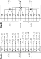
La structure d'un système FS-FBMC est représentée en
Au niveau de l'émetteur, les symboles de modulation QAM à transmettre avec une cadence Nf avec f = 1/T sont regroupés par blocs de taille N, x 0[n], .... x N-1[n] où n est l'indice temporel du bloc. Chaque bloc de N symboles est fourni en parallèle à N voies d'entrée d'un module de prétraitement, 110, dit prétraitement OQAM (Offset QAM). Ce module de prétraitement a pour fonction de démultiplexer la partie réelle et la partie imaginaire des symboles d'entrée avec une fréquence 2 f de sorte que deux échantillons transmis au même instant sur deux sous-canaux successifs ou deux échantillons transmis en deux instants successifs sur un même sous-canal sont l'un réel et l'autre imaginaire. Chacune des N voies de sortie du module de prétraitement 110 correspond à un sous-canal.At the transmitter, the QAM modulation symbols to be transmitted with a rate Nf with f = 1 / T are grouped in blocks of size N, x 0 [ n ] , .... x N -1 [ n ] where n is the time index of the block. Each block of N symbols is provided in parallel with N input channels of a preprocessing module, 110, called preprocessing OQAM (QAM Offset). This pretreatment module has the function of demultiplexing the real part and the imaginary part of the input symbols with a frequency f so that two samples transmitted at the same time on two successive subchannels or two samples transmitted in two successive instants on the same subchannel are one real and the other imaginary. Each of the N output channels of the
Chaque sous-canal est ensuite étalé sur un intervalle de 2K - 1 sous-porteuses adjacentes, centré sur une sous-porteuse centrale du sous-canal. Plus précisément, chaque donnée OQAM est étalée sur 2K -1 sous-porteuses adjacentes et pondérée par la valeur (réelle) prise par la fonction de transfert du filtre de synthèse à la fréquence correspondante.Each subchannel is then spread over an interval of 2 K - 1 adjacent subcarriers, centered on a central subcarrier of the subchannel. More specifically, each OQAM data is spread over 2 K -1 adjacent subcarriers and weighted by the value (actual) taken by the transfer function of the synthesis filter at the corresponding frequency.
On a désigné par 120 le module d'étalement en fréquence et de filtrage par le filtre prototype. Chaque donnée OQAM di [n] en entrée du module 120 est étalée sur 2K - 1 sous-porteuses adjacentes pour donner : ![]()
![]()
Les données de même parité i et i+2 sont séparées spectralement et celles de parités contraires i et i+1 se chevauchent comme représenté en
Les données étalées en fréquence et filtrées font ensuite l'objet d'une IFFT de taille KN en 130.The frequency-spread and filtered data are then subjected to an IFFT of size KN at 130.
Le bloc d'échantillons temporels en sortie de la IFFT est combiné au moyen du module de combinaison 140 comme indiqué en
Le signal ainsi obtenu est ensuite translaté sur une fréquence porteuse.The signal thus obtained is then translated on a carrier frequency.
Après transmission sur le canal 150, le signal reçu, démodulé en bande de base, est échantillonné par le récepteur à la cadence Nf puis converti en blocs de taille KN par le convertisseur série-parallèle 160.After transmission on the
Une FFT glissante (la fenêtre de la FFT glissant de N / 2 échantillons entre deux calculs de FFT) de taille KN est effectuée dans le module FFT, 170, sur des blocs de KN échantillons consécutifs en sortie du convertisseur série-parallèle 160.A sliding FFT (the sliding FFT window of N / 2 samples between two FFT calculations) of size KN is performed in the
Les sorties de la FFT sont ensuite soumises à un filtrage et un désétalement spectral dans le module 180. L'opération de désétalement a lieu dans le domaine fréquentiel comme représenté en ![]()

![]()
On notera que, comme en ![]()
![]()
![]()
![]()
![]()
![]()
![]()
![]()
![]()
![]()
Le désétalement de données réelles est représenté par des traits continus alors que celui des données imaginaires est représenté par des traits en pointillés.The despreading of real data is represented by continuous lines whereas that of the imaginary data is represented by dashed lines.
Les données ![]()
![]()
La technologie FBMC est l'une des technologies candidates à la cinquième génération des systèmes de télécommunication sans fil. En particulier, celle-ci devrait permettre de répondre aux besoins de fragmentation spectrale et d'asynchronisme de transmission des communications de type machine ou MTC (Machine Type Communication).FBMC technology is one of the fifth-generation candidate technologies for wireless telecommunication systems. In particular, this should make it possible to meet the needs of spectral fragmentation and transmission asynchrony of machine-type communications (MTC).
L'application de la technologie FBMC aux systèmes de télécommunication à diversité spatiale de type MIMO (Multiple Input Multiple Output) est toutefois beaucoup plus compliquée qu'en OFDM du fait que la transmission FBMC utilise intrinsèquement l'orthogonalité dans le plan complexe pour éliminer l'interférence entre symboles FBMC.However, the application of FBMC technology to MIMO (Multiple Input Multiple Output) spatial diversity telecommunication systems is much more complicated than in OFDM because FBMC inherently uses orthogonality in the complex plane to eliminate interference between FBMC symbols.
Un codage spatio-temporel par blocs ou STBC (Spatial Time Block Coding) de type Alamouti a été récemment proposé pour un système FBMC dans l'article de
On rappelle tout d'abord qu'un codage Alamouti est un codage STBC (Space Time Block Coding) s'appliquant à une configuration à deux antennes d'émission et une antenne de réception. Sa matrice de codage est donnée par : 
![]()
![]()
![]()
![]()
Les signaux reçus respectivement pendant la première et la seconde utilisation du canal, y 0, y 1 peuvent alors s'exprimer sous la forme : ![]()
![]()
![]()
![]()
En supposant le canal connu, le récepteur estime les symboles transmis à partir d'une combinaison des signaux reçus : 

L'article de Renfors précité fait appel à une technique de filtrage adapté, déjà utilisée pour le codage d'Alamouti en présence d'interférence intersymbole, présentée dans l'article de
Le codage d'Alamouti est effectué par blocs de vecteurs de données d'entrée, un bloc étant constitué d'une séquence de L vecteurs-colonnes et pouvant donc être représenté par une matrice
Si l'on note 
La
Une première séquence de blocs, 401, est formée par un premier bloc de garde 411, un premier bloc de L vecteurs de symboles, ![]()
![]()
Une seconde séquence de blocs, 402, est formé par un premier bloc de garde, 421, un second bloc constitué de L vecteurs de symboles, ![]()
![]()
Les blocs de garde sont constitués de symboles nuls et ont pour objet d'isoler les blocs successifs de l'interférence générée par les blocs adjacents.The guard blocks consist of null symbols and are intended to isolate the successive blocks of the interference generated by the adjacent blocks.
La première séquence de blocs est transmise par la première antenne 491 après modulation FBMC. Le signal obtenu en sortie du modulateur FBMC peut être considéré comme une séquence de symboles FBMC se chevauchant temporellement, comme expliqué en relation avec la
De même, la seconde séquence de blocs est transmise par la seconde antenne 492 après avoir été modulée par un second modulateur FBMC de structure identique au premier.Similarly, the second block sequence is transmitted by the
La
Le récepteur comprend un module d'échantillonnage 510 pour échantillonner le signal reçu en bande de base à la cadence Nf où N est le nombre de sous-porteuses et f est la fréquence des symboles FBMC. Les échantillons sont regroupés sous forme de blocs de taille N par un convertisseur série-parallèle 520.The receiver comprises a
Chaque bloc est filtré par un transmultiplexeur constitué par une batterie de N filtres polyphasés (PPN), 530, puis soumis une FFT de taille N, dans le module de FFT 540, opérant sur les N sorties de ces filtres.Each block is filtered by a transmultiplexer constituted by a battery of N polyphase filters (PPN), 530, then subjected to a FFT of size N , in the
Le récepteur est supposé être synchronisé sur les symboles FBMC, autrement dit le début d'une fenêtre FFT coïncide avec le premier échantillon d'un symbole FBMC (émis par l'une ou l'autre des antennes d'émission). En outre, le récepteur est supposé être synchronisé sur les instants d'utilisation du canal de sorte qu'il connaît les instants de réception des premier et second blocsThe receiver is supposed to be synchronized to the FBMC symbols, ie the beginning of an FFT window coincides with the first sample of an FBMC symbol (emitted by one or the other of the transmitting antennas). In addition, the receiver is supposed to be synchronized on the times of use of the channel so that it knows the times of reception of the first and second blocks
Un démultiplexeur 550 fournit les vecteurs en sortie de la FFT sur une première sortie 551 lors de la première utilisation du canal et sur une seconde sortie 552 lors de la seconde utilisation du canal. Les L vecteurs (de taille N) générés séquentiellement sur la première sortie sont stockés dans une première mémoire tampon 561 configurée sous la forme d'un buffer FIFO (First In First Out). Les L vecteurs générés séquentiellement sur la seconde sortie sont également stockés dans une seconde mémoire tampon 562, configurée sous la forme d'un buffer LIFO (Last In First Out). Le module de conjugaison 570 lit ainsi les L vecteurs dans l'ordre inverse de leur ordre de stockage, de sorte à effectuer un retournement temporel, et effectue une conjugaison complexe de chacun de ces vecteurs.A
Chaque élément d'un vecteur généré sur la première sortie est multiplié en 581 par le conjugué complexe du coefficient du premier canal élémentaire entre la première antenne d'émission et l'antenne de réception, à la fréquence de la sous-porteuse portant l'élément en question (l'opération est symbolisée ici par une multiplication du vecteur en sortie de la mémoire tampon par la matrice ![]()
![]()
![]()
![]()
De manière similaire, chaque élément d'un vecteur généré sur la seconde sortie est multiplié en 582 par le coefficient du canal entre la première antenne d'émission et l'antenne de réception à la fréquence de la sous-porteuse portant l'élément en question (opération symbolisée par une multiplication du vecteur en sortie de la FFT par la matrice H 0) et en 584 par le coefficient du canal entre la seconde antenne d'émission et l'antenne de réception à la fréquence de la même sous-porteuse (opération symbolisée par une multiplication du vecteur en sortie de la FFT par la matrice H 1).Similarly, each element of a vector generated on the second output is multiplied by the
Les vecteurs en sortie du multiplieur 581 sont sommés, élément à élément, avec ceux en sortie du multiplieur 584, dans le sommateur, 591. Les vecteurs successifs en sortie du sommateur 591 sont ensuite fournis à un premier démodulateur OQAM (non représenté).The vectors at the output of the
De manière similaire, les vecteurs en sortie du multiplieur 583 sont soustraits, élément à élément, à ceux en sortie du multiplieur 582, dans le sommateur 592. Les vecteurs successifs en sortie du sommateur 592 sont ensuite fournis à un second démodulateur OQAM (non représenté).Similarly, the vectors at the output of the
Autrement dit, si l'on note 

La méthode de réception décrite ci-dessus fonctionne pour un récepteur FBMC implémenté au moyen d'une batterie de filtres polyphasés. Elle n'est pas applicable à un récepteur FS-FBMC comme décrit en relation avec la partie droite de la
Le but de la présente invention est de proposer une méthode d'émission d'une séquence de blocs de symboles FBMC codée au moyen d'un codage Alamouti par blocs, qui permette une réception très simple par un récepteur FS-FBMC.The object of the present invention is to propose a method of transmitting an encoded FBMC symbol block sequence by means of an Alamouti block coding, which allows a very simple reception by an FS-FBMC receiver.
La présente invention est définie par une méthode de transmission FBMC d'au moins un premier et un second blocs de symboles (
- lors d'une première utilisation du canal de transmission, les vecteurs du premier bloc et les vecteurs du second bloc sont respectivement fournis à la première voie de modulation FBMC et à la seconde voie de modulation FBMC, dans l'ordre de ladite séquence temporelle ;
- le premier bloc est transformé en multipliant les vecteurs de ce bloc par un facteur j L-1 où L est un nombre pair et en inversant l'ordre temporel de la séquence de vecteurs ainsi obtenus, et le second bloc est transformé en multipliant les vecteurs de ce bloc par un facteur -(j L-1) et en inversant l'ordre temporel de la séquence de vecteurs ainsi obtenus;
- lors d'une seconde utilisation du canal de transmission, les vecteurs des premier et second blocs ainsi transformés sont respectivement fournis à la seconde voie de modulation et à la première voie de modulation FBMC.
- during a first use of the transmission channel, the vectors of the first block and the vectors of the second block are respectively provided to the first modulation channel FBMC and the second modulation channel FBMC, in the order of said time sequence;
- the first block is transformed by multiplying the vectors of this block by a factor j L -1 where L is an even number and inverting the temporal order of the sequence of vectors thus obtained, and the second block is transformed by multiplying the vectors of this block by a factor - ( j L -1 ) and by reversing the temporal order of the sequence of vectors thus obtained;
- during a second use of the transmission channel, the vectors of the first and second blocks thus transformed are respectively provided to the second modulation channel and the first modulation channel FBMC.
Selon une première variante, chaque voie de modulation FBMC comprend avantageusement une étape de prétraitement OQAM fournissant des données alternativement réelles et imaginaires, chaque donnée ainsi obtenue étant étalée sur une pluralité 2K - 1 de sous-porteuses adjacentes et filtrée dans le domaine spectral par un filtre prototype pour fournir un vecteur de KN composantes, le vecteur de KN composantes étant soumis à une IFFT de taille KN pour générer un symbole FBMC de KN échantillons, les symboles FBMC consécutifs étant décalés de N / 2 échantillons, chaque symbole FBMC étant combiné avec les K -1 symboles FBMC précédents et les K -1 symboles FBMC suivants pour fournir, après translation en bande RF, un signal d'antenne émis par une antenne associée à ladite voie.According to a first variant, each FBMC modulation channel advantageously comprises an OQAM preprocessing step providing alternately real and imaginary data, each data thus obtained being spread over a plurality 2 K - 1 of adjacent subcarriers and filtered in the spectral domain by a prototype filter for providing a vector of KN components, the vector of KN components being subjected to an IFFT of size KN to generate a symbol FBMC of KN samples, the consecutive symbols FBMC being shifted by N / 2 samples, each symbol FBMC being combined with the K -1 previous FBMC symbols and the following K -1 FBMC symbols to provide, after RF band translation, an antenna signal transmitted by an antenna associated with said channel.
Selon une seconde variante, chaque voie de modulation FBMC comprend une étape de prétraitement OQAM fournissant un vecteur de N composantes alternativement réelles et imaginaires, le vecteur de N composantes étant soumis à une IFFT de taille N pour générer une pluralité sous-canaux, chaque sous-canal étant filtré par un filtre polyphasé, les filtres polyphasés étant des versions translatées en fréquence de 2k/T d'un filtre prototype dont la réponse impulsionnelle est de durée KT où T est la période d'échantillonnage, les sorties des filtres polyphasés étant sur-échantillonnées d'un facteur N/2 et retardées de 0 à N-1 périodes d'échantillonnage avant d'être sommées pour fournir, après translation en bande RF, un signal d'antenne émis par une antenne associée à ladite voie.According to a second variant, each FBMC modulation channel comprises an OQAM preprocessing step providing a vector of N alternately real and imaginary components, the vector of N components being subjected to an IFFT of size N to generate a plurality of sub-channels, each sub-channel. -channel being filtered by a polyphase filter, the polyphase filters being translated versions in frequency of 2 k / T of a prototype filter whose impulse response is of duration KT where T is the sampling period, the outputs of the polyphase filters being oversampled by a factor N / 2 and delayed from 0 to N -1 sampling periods before being summed to provide, after translation in an RF band, an antenna signal transmitted by an antenna associated with said channel.
Selon un premier exemple avantageux de réalisation, lors de la première utilisation du canal, on fournit un bloc de garde constitué par un nombre prédéterminé de vecteurs nuls aux première et seconde voies de modulation avant de leur fournir respectivement les vecteurs du premier bloc et les vecteurs du second bloc, et
lors de la seconde utilisation du canal, on fournit un bloc de garde constitué par ledit nombre prédéterminé de vecteurs nuls aux première et seconde voies de modulation avant de leur fournir respectivement les vecteurs du second bloc transformé et les vecteurs du premier bloc transformé.According to a first advantageous example of embodiment, during the first use of the channel, a guard block constituted by a predetermined number of zero vectors is provided to the first and second modulation channels before supplying them respectively with the vectors of the first block and the vectors. the second block, and
during the second use of the channel, a guard block constituted by said predetermined number of zero vectors is provided to the first and second modulation channels before supplying them respectively the vectors of the second transformed block and the vectors of the first transformed block.
De préférence, le nombre prédéterminé de vecteurs nuls est choisi égal à K + E où E est l'étalement temporel du canal de transmission exprimée en nombre d'échantillons.Preferably, the predetermined number of null vectors is chosen equal to K + E where E is the time spread of the transmission channel expressed in number of samples.
Selon un second exemple avantageux de réalisation, lors de la première utilisation du canal, on fournit des premier et second préambules, constitués par un nombre prédéterminé de vecteurs connus du récepteur, aux première et seconde voies de modulation avant de leur fournir respectivement les vecteurs du premier bloc et les vecteurs du second bloc, et
lors de la seconde utilisation du canal, on fournit un bloc de garde constitué par ledit nombre prédéterminé de vecteurs nuls aux première et seconde voies de modulation avant de leur fournir respectivement les vecteurs du second bloc transformé et les vecteurs du premier bloc transformé.According to a second advantageous example of embodiment, during the first use of the channel, first and second preambles, constituted by a predetermined number of vectors known to the receiver, are provided to the first and second modulation channels before supplying them respectively with the vectors of the first block and the vectors of the second block, and
during the second use of the channel, a guard block constituted by said predetermined number of zero vectors is provided to the first and second modulation channels before supplying them respectively the vectors of the second transformed block and the vectors of the first transformed block.
De préférence, ledit nombre prédéterminé est égal à K + E où E est l'étalement temporel du canal de transmission exprimée en nombre d'échantillons.Preferably, said predetermined number is equal to K + E where E is the time spread of the transmission channel expressed in number of samples.
Le nombre L peut être typiquement une puissance de 2.The number L can be typically a power of 2.
L'invention concerne également un émetteur FBMC adapté à transmettre au moins un premier et un second blocs de symboles (
- lors d'une première utilisation du canal de transmission, les vecteurs du premier bloc et les vecteurs du second bloc sont respectivement fournis à la première voie de modulation FBMC et à la seconde voie de modulation FBMC, dans l'ordre de ladite séquence temporelle, et que ledit émetteur comprend :
- des premiers moyens de transformation adaptés à transformer le premier bloc en multipliant les vecteurs de ce bloc par un facteur j L-1, où L est un nombre pair, et en inversant l'ordre temporel de la séquence de vecteurs ainsi obtenus, et
- des seconds moyens de transformation adaptés à transformer le second bloc en multipliant les vecteurs de ce bloc par un facteur -(j L-1) et en inversant l'ordre temporel de la séquence de vecteurs ainsi obtenus ;
- l'émetteur FBMC étant configuré de manière à ce que, lors d'une seconde utilisation du canal de transmission, les premiers et seconds moyens de transformation fournissent les vecteurs des premier et second blocs ainsi transformés à la seconde voie de modulation et à la première voie de modulation FBMC.
- during a first use of the transmission channel, the vectors of the first block and the vectors of the second block are respectively provided to the first modulation channel FBMC and the second modulation channel FBMC, in the order of said time sequence, and that said transmitter comprises:
- first transformation means adapted to transform the first block by multiplying the vectors of this block by a factor j L -1 , where L is an even number, and inverting the temporal order of the sequence of vectors thus obtained, and
- second transforming means adapted to transform the second block by multiplying the vectors of this block by a factor - ( j L -1 ) and inverting the temporal order of the sequence of vectors thus obtained;
- the transmitter FBMC being configured so that, during a second use of the transmission channel, the first and second transformation means provide the vectors of the first and second blocks thus transformed to the second modulation channel and to the first FBMC modulation channel.
D'autres caractéristiques et avantages de l'invention apparaîtront à la lecture de modes de réalisation préférentiels de l'invention faite en référence aux figures jointes parmi lesquelles :
- La
Fig. 1 représente de manière schématique un système de télécommunication FS-FBMC connu de l'état de la technique ; - La
Fig. 2A illustre l'étalement spectral réalisé en amont du module IFFT de laFig. 1 ; - La
Fig. 2B illustre le désétalement spectral réalisé en aval du module FFT dans laFig. 1 ; - La
Fig. 3 illustre la combinaison des symboles FBMC dans laFig. 1 ; - La
Fig. 4 représente schématiquement l'émission de deux séquences de blocs de symboles par un émetteur FBMC utilisant un codage d'Alamouti par blocs connu de l'état de la technique ; - La
Fig. 5 représente schématiquement l'architecture d'un récepteur FBMC permettant de recevoir les séquences de blocs de symboles émises par l'émetteur de laFig. 4 ; - La
Fig. 6 représente schématiquement l'architecture d'un récepteur FS-FBMC, permettant de recevoir des séquences de blocs de symboles codés par un codage d'Alamouti par blocs ; - La
Fig. 7A représente schématiquement l'émission de deux séquences de blocs de symboles par un émetteur FBMC utilisant un premier codage d'Alamouti par blocs, selon un premier exemple de réalisation de l'invention ; - La
Fig. 7B représente schématiquement l'émission de deux séquences de blocs de symboles par un émetteur FBMC utilisant un second codage d'Alamouti par blocs, selon un second exemple de réalisation de l'invention; - La
Fig. 8 représente schématiquement l'architecture d'un émetteur FS-FBMC, permettant d'émettre des séquences de blocs de symboles selon lesFigs. 7A et7B .
- The
Fig. 1 schematically shows a FS-FBMC telecommunication system known from the state of the art; - The
Fig. 2A illustrates the spectral spread made upstream of the IFFT module of theFig. 1 ; - The
Fig. 2B illustrates the spectral despreading performed downstream of the FFT module in theFig. 1 ; - The
Fig. 3 illustrates the combination of FBMC symbols in theFig. 1 ; - The
Fig. 4 schematically represents the transmission of two symbol block sequences by a transmitter FBMC using a block Alamouti coding known from the state of the art; - The
Fig. 5 schematically represents the architecture of a receiver FBMC for receiving the symbol block sequences transmitted by the transmitter of theFig. 4 ; - The
Fig. 6 schematically shows the architecture of an FS-FBMC receiver, for receiving symbol block sequences encoded by block Alamouti encoding; - The
Fig. 7A schematically shows the transmission of two symbol block sequences by a transmitter FBMC using a first block Alamouti encoding, according to a first embodiment of the invention; - The
Fig. 7B schematically shows the transmission of two symbol block sequences by a transmitter FBMC using a second block Alamouti encoding, according to a second embodiment of the invention; - The
Fig. 8 schematically represents the architecture of an FS-FBMC transmitter, making it possible to transmit symbol block sequences according to theFigs. 7A and7B .
Pour faciliter la compréhension des notations, nous considérerons d'abord un émetteur FS-FBMC, tel que décrit en relation avec la
A la différence des notations précédentes, les vecteurs-colonnes X m , m = 0,...,L-1, de taille N, représenteront dans la suite des vecteurs de données d'entrée, autrement dit des données à l'entrée du modulateur OQAM. Les éléments de ces vecteurs sont donc à valeurs réelles.Unlike the previous notations, the vector-columns X m , m = 0, ..., L- 1 , of size N, will represent in the following vectors of input data, in other words data at the input the OQAM modulator. The elements of these vectors are therefore real values.
Le signal émis par l'émetteur à l'instant m peut être représenté par un vecteur-colonne Z m de taille KN dont les éléments sont des échantillons à la fréquence Nf. Le vecteur Z m peut s'exprimer en fonction des vecteurs X m-(K-1),...,X m ,...,X m+(K-1) de données d'entrée, soit : 
- où ⊙ est le produit de Hadamard, F est la matrice de transformée de Fourier discrète de taille KN×KN, G est une matrice de taille KN×N représentant l'étalement spectral et la fonction de transfert du filtre prototype dans le domaine fréquentiel, soit :

- M m est un vecteur-colonne de taille N qui traduit la modulation OQAM, à savoir un vecteur dont les éléments sont donnés par :

- et Q ℓ est une matrice de décalage de ℓ échantillons, de taille KN×KN définie par :

- where ⊙ is the product of Hadamard, F is the discrete Fourier transform matrix of size KN × KN, G is a matrix of size KN × N representing the spectral spread and the transfer function of the prototype filter in the frequency domain, is :
- M m is a vector-column of size N which translates the OQAM modulation, namely a vector whose elements are given by:
- and Q ℓ is an offset matrix of ℓ samples of size KN × KN defined by:
On comprendra que les termes sous le signe somme dans l'expression (8) représentent les 2K - 1 symboles FBMC qui sont combinés en
Le signal reçu par le récepteur FBMC à l'instant m peut de manière similaire s'exprimer sous la forme d'un vecteur de données en sortie du démodulateur OQAM, noté ici Y m , de taille KN. Le vecteur Y m peut s'exprimer en fonction du vecteur Z m représentant le signal émis, soit en faisant abstraction du terme de bruit: ![]()

![]()
![]()
![]()
On notera que G H = G T étant donné que les coefficients de la matrice de transfert du filtre sont réels.Note that G H = G T given that the coefficients of the transfer matrix of the filter are real.
On suppose maintenant que l'on effectue un codage d'Alamouti par blocs, avec une matrice de codage définie par : 
Comme décrit ci-après, on peut utiliser un récepteur implémenté dans le domaine fréquentiel (récepteur FS-FBMC) et combiner les deux blocs en sortie du module de FFT (module 170 de la
On note ![]()
![]()
![]()
![]()
![]()
![]()
![]()
![]()
Lors de la première utilisation du canal, le vecteur ![]()

![]()
![]()
![]()
De même, lors de la seconde utilisation du canal, le vecteur ![]()

On notera que les matrices de transfert des canaux élémentaire, H 0 et H 1 sont ici de taille KN×KN en raison de l'étalement spectral.Likewise, during the second use of the channel, the vector ![]()
It will be noted that the transfer matrices of the elementary channels H 0 and H 1 here are of size KN × KN because of the spectral spreading.
Si l'on transforme le bloc de vecteurs ![]()

![]()
![]()
![]()

![]()
![]()
![]()
![]()
On peut alors estimer les vecteurs de données transmis ![]()
![]()
![]()
![]()
![]()
![]()

![]()
![]()
![]()
![]()
![]()
![]()
![]()
![]()
![]()
![]()
La
Le récepteur comprend un module d'échantillonnage 610 pour échantillonner le signal reçu en bande de base à la cadence Nf où N est le nombre de sous-porteuses et f est la fréquence des symboles FBMC. Les échantillons sont regroupés sous forme de blocs de taille KN par un convertisseur série-parallèle 620.The receiver comprises a
Le récepteur est supposé être synchronisé sur les symboles FBMC, autrement dit le début d'une fenêtre FFT coïncide avec le premier échantillon d'un symbole FBMC (émis par l'une ou l'autre des antennes d'émission). En outre, le récepteur est supposé être synchronisé sur les instants d'utilisation du canal de sorte qu'il connaît les instants de réception des premier et second blocs.The receiver is supposed to be synchronized to the FBMC symbols, ie the beginning of an FFT window coincides with the first sample of an FBMC symbol (emitted by one or the other of the transmitting antennas). In addition, the receiver is supposed to be synchronized on the times of use of the channel so that it knows the times of reception of the first and second blocks.
Les blocs d'échantillons sont soumis à une FFT de taille KN dans le module de FFT 630.The sample blocks are subjected to a FFT of size KN in the
Un démultiplexeur 640 fournit les vecteurs en sortie de la FFT sur une première sortie 641 lors de la première utilisation du canal et sur une seconde sortie 642 lors de la seconde utilisation du canal. Les L vecteurs (de taille KN) générés séquentiellement sur la première sortie sont stockés dans une première mémoire tampon 651 configurée sous forme de FIFO. Les L vecteurs générés séquentiellement sur la seconde sortie sont également stockés dans une seconde mémoire tampon 652 configurée sous forme de LIFO. Le module 660 lit ainsi les L vecteurs dans l'ordre inverse de l'ordre de stockage (LIFO), de sorte à effectuer un retournement temporel, et effectue en outre une conjugaison complexe de chacun de ces vecteurs. Un multiplieur 670 multiplie les éléments des vecteurs en sortie du module 660 par (i) L-1, autrement dit par j si L est un nombre pair. On pourra notamment choisir L égal à une puissance de 2 : L = 2ℓ avec ℓ entier strictement supérieur à 1.A
Chaque élément d'un vecteur généré sur la première sortie est multiplié en 681 par le conjugué complexe du coefficient du premier canal élémentaire entre la première antenne d'émission et l'antenne de réception, à la fréquence de la sous-porteuse portant l'élément en question (l'opération est symbolisée ici par une multiplication du vecteur en sortie de la mémoire tampon par la matrice ![]()
![]()
![]()
![]()
De manière similaire, chaque élément d'un vecteur généré sur la seconde sortie est multiplié en 682 par le coefficient du canal entre la première antenne d'émission et l'antenne de réception à la fréquence de la sous-porteuse portant l'élément en question (opération symbolisée par une multiplication du vecteur en sortie de la FFT par la matrice H 0) et en 684 par le coefficient du canal entre la seconde antenne d'émission et l'antenne de réception à la fréquence de la même sous-porteuse (opération symbolisée par une multiplication du vecteur en sortie de la FFT par la matrice H 1).Similarly, each element of a vector generated on the second output is multiplied by 682 by the coefficient of the channel between the first transmitting antenna and the receiving antenna at the frequency of the subcarrier carrying the element. question (operation symbolized by a multiplication of the vector at the output of the FFT by the matrix H 0 ) and at 684 by the channel coefficient between the second transmitting antenna and the receiving antenna at the frequency of the same subcarrier (Operation symbolized by a multiplication of the vector at the output of the FFT by the matrix H 1 ).
Les vecteurs en sortie du multiplieur 681 sont sommés, élément à élément, avec ceux en sortie du multiplieur 684, dans le sommateur 691. Les vecteurs successifs, de taille N, en sortie du sommateur 691 sont ensuite fournis à un premier module de désétalement spectral et de filtrage 695.The vectors at the output of the
De même, les vecteurs en sortie du multiplieur 682 sont soustraits, élément à élément, avec ceux en sortie du multiplieur 683 dans le sommateur 692. Les vecteurs successifs, de taille N, en sortie du sommateur 692 sont ensuite fournis à un second module de désétalement spectral et de filtrage 696.Likewise, the vectors at the output of the
Les vecteurs obtenus par les premier et second modules 695 et 696 font ensuite l'objet d'une démodulation OQAM (non représentée) pour obtenir les vecteurs de données estimées ![]()
![]()
![]()
![]()
La présente invention repose sur le constat que la structure du récepteur de la 
Dans ce cas, la multiplication par le facteur (j L-1) peut être supprimée à la réception et par conséquent le multiplieur 670 peut être omis.In this case, the multiplication by the factor ( j L -1 ) can be suppressed on reception and therefore the
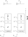
La
Les blocs de données à émettre sont considérés ici en amont de la modulation OQAM.The blocks of data to be transmitted are considered here upstream of the OQAM modulation.
Une première séquence de blocs, 701, est formée par un premier bloc de garde 711, un premier bloc de L vecteurs de données d'entrée,
Une seconde séquence de blocs, 702, est formée par un premier bloc de garde, 712, un second bloc de L vecteurs de données d'entrée,
La taille L des blocs de données est supposée paire, autrement dit (j L-1) = j ou (j L-1) = -j. The size L of the data blocks is assumed to be even, ie ( j L -1 ) = j or ( j L -1 ) = -j.
Les blocs de garde sont constitués de vecteurs nuls pour prévenir une interférence entre les blocs de données et les blocs transformés. Le nombre de vecteurs nuls dans les blocs de garde est avantageusement égal à K + E où K est la longueur du filtre prototype et E est l'étalement temporel du canal exprimé en nombre d'échantillons à la fréquence d'échantillonnage (Nf).The guard blocks consist of null vectors to prevent interference between the data blocks and the transformed blocks. The number of null vectors in the guard blocks is advantageously equal to K + E where K is the length of the prototype filter and E is the time delay of the channel expressed in number of samples at the sampling frequency ( Nf ).
Les première et seconde séquences sont respectivement transmises par les première et seconde antennes, 791 et 792, après modulation FBMC.The first and second sequences are respectively transmitted by the first and second antennas, 791 and 792, after FBMC modulation.
La
Le second exemple est identique au premier à la différence près que le premier bloc de garde est remplacé dans la première séquence par un premier préambule 711' et dans la seconde séquence par un second préambule, 712'. Les autres blocs restent inchangés et ne sont donc pas décrits à nouveau.The second example is identical to the first, with the difference that the first block of guard is replaced in the first sequence by a first preamble 711 'and in the second sequence by a second preamble, 712'. The other blocks remain unchanged and are therefore not described again.
Les premier et second préambules génèrent une interférence affectant les premiers symboles des blocs ![]()
![]()
![]()
![]()
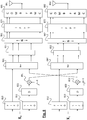
La
Les blocs de symboles à transmettre sont notés comme précédemment ![]()
![]()
![]()
![]()
Les modules 861-862,871-872,881-882 sont respectivement identiques aux modules 820, 830, 840 et leur description ne sera donc pas reprise ici. Les signaux en sortie des modules de combinaison 881 et 882 sont translatés en bande RF avant d'être transmis respectivement par les antennes 891 et 892.The modules 861-862,871-872,881-882 are respectively identical to the modules 820, 830 and 840 and their description will therefore not be repeated here. The signals at the output of the
La
Les éléments référencés 910 à 952 sont respectivement identiques aux éléments 810 à 852.The elements referenced 910 to 952 are respectively identical to the
Plus précisément, l'émetteur comprend deux voies de modulation FBMC. Pour chacune de ces voies, à la différence du premier mode de réalisation, le vecteur de données en sortie du module OQAM est fourni à un banc de filtres de synthèse, constitué par un module IFFT de taille N (961, 962), une pluralité N de filtres polyphasés (971, 972) et une pluralité N de sur-échantillonneurs (981, 982) de facteur N / 2, en sortie des différents filtres polyphasés et enfin une pluralité de retards arrangés en parallèle et variant de 0 à N - 1 périodes d'échantillonnage. Les filtres polyphasés sont des versions translatées en fréquence de 2k/T du filtre prototype dont la réponse impulsionnelle est de durée KT. More precisely, the transmitter comprises two FBMC modulation channels. For each of these channels, unlike the first embodiment, the output data vector of the OQAM module is provided to a synthesis filter bank consisting of an IFFT module of size N (961, 962), a plurality N of polyphase filters (971, 972) and a plurality N of oversamplers (981, 982) of factor N / 2, at the output of the different polyphase filters and finally a plurality of delays arranged in parallel and varying from 0 to N - 1 sampling periods. Polyphase filters are frequency-shifted versions of 2 k / T of the prototype filter whose impulse response is of duration KT.
Les sous-canaux en sortie de la IFFT sont chacun filtrés par un filtre polyphasé. Les sorties des N filtres polyphasés, sur-échantillonnées et retardées, sont sommées par un additionneur (981, 982). Le signal en sortie de l'additionneur est translaté en bande RF pour fournir un signal d'antenne qui est ensuite émis par l'antenne associée à la voie (991, 992).The subchannels at the output of the IFFT are each filtered by a polyphase filter. The outputs of the N polyphase filters, oversampled and delayed, are summed by a adder (981, 982). The output signal of the adder is translated in RF band to provide an antenna signal which is then transmitted by the antenna associated with the channel (991, 992).
Claims (9)
lors de la première utilisation du canal, on fournit un bloc de garde constitué par un nombre prédéterminé de vecteurs nuls aux première et seconde voies de modulation avant de leur fournir respectivement les vecteurs du premier bloc et les vecteurs du second bloc, et que
lors de la seconde utilisation du canal, on fournit un bloc de garde constitué par ledit nombre prédéterminé de vecteurs nuls aux première et seconde voies de modulation avant de leur fournir respectivement les vecteurs du second bloc transformé et les vecteurs du premier bloc transformé.FBMC transmission method according to one of the preceding claims, characterized in that
during the first use of the channel, a guard block consisting of a predetermined number of zero vectors is provided to the first and second modulation channels before supplying them respectively with the vectors of the first block and the vectors of the second block, and
during the second use of the channel, a guard block constituted by said predetermined number of zero vectors is provided to the first and second modulation channels before supplying them respectively the vectors of the second transformed block and the vectors of the first transformed block.
lors de la première utilisation du canal, on fournit des premier et second préambules, constitués par un nombre prédéterminé de vecteurs connus du récepteur, aux première et seconde voies de modulation avant de leur fournir respectivement les vecteurs du premier bloc et les vecteurs du second bloc, et que
lors de la seconde utilisation du canal, on fournit un bloc de garde constitué par ledit nombre prédéterminé de vecteurs nuls aux première et seconde voies de modulation avant de leur fournir respectivement les vecteurs du second bloc transformé et les vecteurs du premier bloc transformé.FBMC transmission method according to one of claims 1 to 3, characterized in that
during the first use of the channel, first and second preambles, constituted by a predetermined number of vectors known to the receiver, are provided to the first and second modulation channels before supplying them respectively the vectors of the first block and the vectors of the second block , and
during the second use of the channel, a guard block constituted by said predetermined number of zero vectors is provided to the first and second modulation channels before supplying them respectively the vectors of the second transformed block and the vectors of the first transformed block.
Applications Claiming Priority (1)
| Application Number | Priority Date | Filing Date | Title |
|---|---|---|---|
| FR1653276A FR3050344B1 (en) | 2016-04-13 | 2016-04-13 | TRANSMITTER FOR FBMC SYSTEM WITH SPATIO-TEMPORAL CODING OF BLOCKED ALAMOUTI TYPE |
Publications (2)
| Publication Number | Publication Date |
|---|---|
| EP3232626A1 true EP3232626A1 (en) | 2017-10-18 |
| EP3232626B1 EP3232626B1 (en) | 2021-03-03 |
Family
ID=56611342
Family Applications (1)
| Application Number | Title | Priority Date | Filing Date |
|---|---|---|---|
| EP17166062.4A Active EP3232626B1 (en) | 2016-04-13 | 2017-04-11 | Transmitter for fbmc system with alamouti space-time block coding |
Country Status (3)
| Country | Link |
|---|---|
| US (1) | US9967060B2 (en) |
| EP (1) | EP3232626B1 (en) |
| FR (1) | FR3050344B1 (en) |
Cited By (1)
| Publication number | Priority date | Publication date | Assignee | Title |
|---|---|---|---|---|
| CN109547181A (en) * | 2018-10-08 | 2019-03-29 | 华中科技大学 | A kind of short filter, single-carrier system and multicarrier system |
Families Citing this family (4)
| Publication number | Priority date | Publication date | Assignee | Title |
|---|---|---|---|---|
| EP3206353B1 (en) * | 2016-02-09 | 2020-02-05 | Technische Universität München | Filter banks and methods for operating filter banks |
| WO2017184035A1 (en) * | 2016-04-19 | 2017-10-26 | Telefonaktiebolaget Lm Ericsson (Publ) | Faster-than-nyquist signaling for fbmc burst transmissions |
| CN108540271A (en) * | 2018-03-27 | 2018-09-14 | 西安电子科技大学 | A kind of Alamouti transmission methods, wireless communication system suitable for FBMC/OQAM |
| CN115412207B (en) * | 2022-08-29 | 2024-02-23 | 上海金卓科技有限公司 | Encoding method and device and decoding method and device for space-time-frequency block code |
Citations (1)
| Publication number | Priority date | Publication date | Assignee | Title |
|---|---|---|---|---|
| US20140348252A1 (en) * | 2011-12-23 | 2014-11-27 | Orange | Method for transmitting at least one multi-carrier signal consisting of ofdm-oqam symbols |
-
2016
- 2016-04-13 FR FR1653276A patent/FR3050344B1/en not_active Expired - Fee Related
-
2017
- 2017-04-11 EP EP17166062.4A patent/EP3232626B1/en active Active
- 2017-04-12 US US15/485,700 patent/US9967060B2/en active Active
Patent Citations (1)
| Publication number | Priority date | Publication date | Assignee | Title |
|---|---|---|---|---|
| US20140348252A1 (en) * | 2011-12-23 | 2014-11-27 | Orange | Method for transmitting at least one multi-carrier signal consisting of ofdm-oqam symbols |
Non-Patent Citations (7)
| Title |
|---|
| B. HIROSAKI: "An orthogonally multiplexed QAM system using the discrète Fourier transform", IEEE TRANS ON COMM., vol. 29, no. 7, July 1981 (1981-07-01), pages 982 - 989, XP000568062, DOI: doi:10.1109/TCOM.1981.1095093 |
| E. LINDSKOG ET AL.: "A transmit scheme for channels with intersymbol interference", PROC. IEEE OF INT'L CONF. ON COMMUNICATIONS, June 2000 (2000-06-01), pages 307 - 311 |
| M. BELLANGER ET AL., FBMC PHYSICAL LAYER : A PRIMER, Retrieved from the Internet <URL:www.ict-phydyas.org> |
| M. RENFORS ET AL.: "A block-Alamouti scheme for filter bank based multicarrier transmission", PROCEEDINGS OF EUROPEAN WIRELESS CONFÉRENCE EW 2010, 12 April 2010 (2010-04-12), pages 1031 - 1037, XP031688570 |
| MARKKU RENFORS ET AL: "A block-Alamouti scheme for filter bank based multicarrier transmission", WIRELESS CONFERENCE (EW), 2010 EUROPEAN, IEEE, PISCATAWAY, NJ, USA, 12 April 2010 (2010-04-12), pages 1031 - 1037, XP031688570, ISBN: 978-1-4244-5999-5 * |
| P. SIOHAN ET AL.: "Analysis and design of OFDM/OQAM systems based on filterbank theory", IEEE TRANS. ON SIGNAL PROCESSING, vol. 50, no. 5, May 2002 (2002-05-01), pages 1170 - 1183, XP002681222, DOI: doi:10.1109/78.995073 |
| R ZAKARIA ET AL: "On interference cancellation in Alamouti coding scheme for filter bank based multicarrier systems", 27 August 2013 (2013-08-27), XP055324856, Retrieved from the Internet <URL:http://ieeexplore.ieee.org/iel7/6629682/6629683/06629689.pdf> [retrieved on 20161130] * |
Cited By (1)
| Publication number | Priority date | Publication date | Assignee | Title |
|---|---|---|---|---|
| CN109547181A (en) * | 2018-10-08 | 2019-03-29 | 华中科技大学 | A kind of short filter, single-carrier system and multicarrier system |
Also Published As
| Publication number | Publication date |
|---|---|
| FR3050344B1 (en) | 2019-05-03 |
| FR3050344A1 (en) | 2017-10-20 |
| EP3232626B1 (en) | 2021-03-03 |
| US20170302408A1 (en) | 2017-10-19 |
| US9967060B2 (en) | 2018-05-08 |
Similar Documents
| Publication | Publication Date | Title |
|---|---|---|
| EP3232626B1 (en) | Transmitter for fbmc system with alamouti space-time block coding | |
| EP2846506B1 (en) | Fbmc receiver with carrier frequency offset compensation | |
| EP2484075B1 (en) | Systems for the multicarrier transmission of digital data and transmission methods using such systems | |
| EP2879341B1 (en) | Channel-estimation method for FBMC telecommunication system | |
| EP2156590B1 (en) | Transmission and reception of multicarrier spread-spectrum signals | |
| EP0610988B1 (en) | Multi-user spread spectrum communication system | |
| EP1035699B1 (en) | Method for isolating a block frequency from a block formatted signal | |
| EP2253114B1 (en) | Methods for transmitting and receiving a multiple carrier signal including a hold interval, and corresponding computer software products, transmission and reception devices, and signal | |
| EP3300325B1 (en) | Ofdm transmitter with block filtering and corresponding transceiver system | |
| EP3042480B1 (en) | Method and apparatus for transmission of complex data symbol blocks, method and apparatus for reception and corresponding computer programs | |
| FR2935856A1 (en) | DIGITAL MULTI-CHANNEL SIGNAL TRANSMISSION SYSTEM USING FILTER BENCHES AND MEMORY PRELOADING FOR INITIALIZATION | |
| EP3220592B1 (en) | Method of synchronising an fbmc system by means of an rach channel | |
| EP3370381B1 (en) | System for transmitting/receiving fbmc-mimo with ml detection | |
| EP3244547B1 (en) | Mimo-fbmc transmitter/receiver with linear precoding implemented in the frequency domain | |
| EP3232627B1 (en) | Receiver for fbmc system with alamouti space-time block coding | |
| EP1244242B1 (en) | Global MMSE equalisation | |
| EP1244243A1 (en) | Global MMSE equalisation | |
| Nadal | Filtered multicarrier waveforms in the context of 5G: novel algorithms and architecture optimizations | |
| WO2002084934A1 (en) | Predistortion of multicarrier signals in a two-way transmission system | |
| FR2800954A1 (en) | MULTI-CARRIER DIGITAL TRANSMISSION SYSTEM USING OQAM TRANSMULTIPLEXER | |
| FR2830389A1 (en) | Channel estimation and time synchronization system for HiperLan2 combines functions | |
| FR3030965A1 (en) | METHOD AND DEVICE FOR TRANSMITTING, METHOD AND DEVICE FOR RECEIVING | |
| FR2897494A1 (en) | METHOD FOR RECEIVING A SIGNAL IMPLEMENTING IMPROVED ESTIMATION OF A PROPAGATION CHANNEL, RECEIVING DEVICE AND CORRESPONDING COMPUTER PROGRAM PRODUCT. |
Legal Events
| Date | Code | Title | Description |
|---|---|---|---|
| PUAI | Public reference made under article 153(3) epc to a published international application that has entered the european phase |
Free format text: ORIGINAL CODE: 0009012 |
|
| STAA | Information on the status of an ep patent application or granted ep patent |
Free format text: STATUS: REQUEST FOR EXAMINATION WAS MADE |
|
| 17P | Request for examination filed |
Effective date: 20170411 |
|
| AK | Designated contracting states |
Kind code of ref document: A1 Designated state(s): AL AT BE BG CH CY CZ DE DK EE ES FI FR GB GR HR HU IE IS IT LI LT LU LV MC MK MT NL NO PL PT RO RS SE SI SK SM TR |
|
| AX | Request for extension of the european patent |
Extension state: BA ME |
|
| GRAP | Despatch of communication of intention to grant a patent |
Free format text: ORIGINAL CODE: EPIDOSNIGR1 |
|
| STAA | Information on the status of an ep patent application or granted ep patent |
Free format text: STATUS: GRANT OF PATENT IS INTENDED |
|
| INTG | Intention to grant announced |
Effective date: 20200924 |
|
| RIN1 | Information on inventor provided before grant (corrected) |
Inventor name: DORE, JEAN-BAPTISTE |
|
| GRAS | Grant fee paid |
Free format text: ORIGINAL CODE: EPIDOSNIGR3 |
|
| STAA | Information on the status of an ep patent application or granted ep patent |
Free format text: STATUS: GRANT OF PATENT IS INTENDED |
|
| GRAA | (expected) grant |
Free format text: ORIGINAL CODE: 0009210 |
|
| STAA | Information on the status of an ep patent application or granted ep patent |
Free format text: STATUS: THE PATENT HAS BEEN GRANTED |
|
| AK | Designated contracting states |
Kind code of ref document: B1 Designated state(s): AL AT BE BG CH CY CZ DE DK EE ES FI FR GB GR HR HU IE IS IT LI LT LU LV MC MK MT NL NO PL PT RO RS SE SI SK SM TR |
|
| REG | Reference to a national code |
Ref country code: GB Ref legal event code: FG4D Free format text: NOT ENGLISH |
|
| REG | Reference to a national code |
Ref country code: AT Ref legal event code: REF Ref document number: 1368469 Country of ref document: AT Kind code of ref document: T Effective date: 20210315 Ref country code: CH Ref legal event code: EP |
|
| REG | Reference to a national code |
Ref country code: DE Ref legal event code: R096 Ref document number: 602017033639 Country of ref document: DE |
|
| REG | Reference to a national code |
Ref country code: IE Ref legal event code: FG4D Free format text: LANGUAGE OF EP DOCUMENT: FRENCH |
|
| REG | Reference to a national code |
Ref country code: LT Ref legal event code: MG9D |
|
| PG25 | Lapsed in a contracting state [announced via postgrant information from national office to epo] |
Ref country code: FI Free format text: LAPSE BECAUSE OF FAILURE TO SUBMIT A TRANSLATION OF THE DESCRIPTION OR TO PAY THE FEE WITHIN THE PRESCRIBED TIME-LIMIT Effective date: 20210303 Ref country code: HR Free format text: LAPSE BECAUSE OF FAILURE TO SUBMIT A TRANSLATION OF THE DESCRIPTION OR TO PAY THE FEE WITHIN THE PRESCRIBED TIME-LIMIT Effective date: 20210303 Ref country code: GR Free format text: LAPSE BECAUSE OF FAILURE TO SUBMIT A TRANSLATION OF THE DESCRIPTION OR TO PAY THE FEE WITHIN THE PRESCRIBED TIME-LIMIT Effective date: 20210604 Ref country code: NO Free format text: LAPSE BECAUSE OF FAILURE TO SUBMIT A TRANSLATION OF THE DESCRIPTION OR TO PAY THE FEE WITHIN THE PRESCRIBED TIME-LIMIT Effective date: 20210603 Ref country code: LT Free format text: LAPSE BECAUSE OF FAILURE TO SUBMIT A TRANSLATION OF THE DESCRIPTION OR TO PAY THE FEE WITHIN THE PRESCRIBED TIME-LIMIT Effective date: 20210303 Ref country code: BG Free format text: LAPSE BECAUSE OF FAILURE TO SUBMIT A TRANSLATION OF THE DESCRIPTION OR TO PAY THE FEE WITHIN THE PRESCRIBED TIME-LIMIT Effective date: 20210603 |
|
| REG | Reference to a national code |
Ref country code: NL Ref legal event code: MP Effective date: 20210303 |
|
| REG | Reference to a national code |
Ref country code: AT Ref legal event code: MK05 Ref document number: 1368469 Country of ref document: AT Kind code of ref document: T Effective date: 20210303 |
|
| PG25 | Lapsed in a contracting state [announced via postgrant information from national office to epo] |
Ref country code: RS Free format text: LAPSE BECAUSE OF FAILURE TO SUBMIT A TRANSLATION OF THE DESCRIPTION OR TO PAY THE FEE WITHIN THE PRESCRIBED TIME-LIMIT Effective date: 20210303 Ref country code: PL Free format text: LAPSE BECAUSE OF FAILURE TO SUBMIT A TRANSLATION OF THE DESCRIPTION OR TO PAY THE FEE WITHIN THE PRESCRIBED TIME-LIMIT Effective date: 20210303 Ref country code: LV Free format text: LAPSE BECAUSE OF FAILURE TO SUBMIT A TRANSLATION OF THE DESCRIPTION OR TO PAY THE FEE WITHIN THE PRESCRIBED TIME-LIMIT Effective date: 20210303 Ref country code: SE Free format text: LAPSE BECAUSE OF FAILURE TO SUBMIT A TRANSLATION OF THE DESCRIPTION OR TO PAY THE FEE WITHIN THE PRESCRIBED TIME-LIMIT Effective date: 20210303 |
|
| PG25 | Lapsed in a contracting state [announced via postgrant information from national office to epo] |
Ref country code: NL Free format text: LAPSE BECAUSE OF FAILURE TO SUBMIT A TRANSLATION OF THE DESCRIPTION OR TO PAY THE FEE WITHIN THE PRESCRIBED TIME-LIMIT Effective date: 20210303 |
|
| PG25 | Lapsed in a contracting state [announced via postgrant information from national office to epo] |
Ref country code: CZ Free format text: LAPSE BECAUSE OF FAILURE TO SUBMIT A TRANSLATION OF THE DESCRIPTION OR TO PAY THE FEE WITHIN THE PRESCRIBED TIME-LIMIT Effective date: 20210303 Ref country code: EE Free format text: LAPSE BECAUSE OF FAILURE TO SUBMIT A TRANSLATION OF THE DESCRIPTION OR TO PAY THE FEE WITHIN THE PRESCRIBED TIME-LIMIT Effective date: 20210303 Ref country code: SM Free format text: LAPSE BECAUSE OF FAILURE TO SUBMIT A TRANSLATION OF THE DESCRIPTION OR TO PAY THE FEE WITHIN THE PRESCRIBED TIME-LIMIT Effective date: 20210303 Ref country code: AT Free format text: LAPSE BECAUSE OF FAILURE TO SUBMIT A TRANSLATION OF THE DESCRIPTION OR TO PAY THE FEE WITHIN THE PRESCRIBED TIME-LIMIT Effective date: 20210303 |
|
| PG25 | Lapsed in a contracting state [announced via postgrant information from national office to epo] |
Ref country code: IS Free format text: LAPSE BECAUSE OF FAILURE TO SUBMIT A TRANSLATION OF THE DESCRIPTION OR TO PAY THE FEE WITHIN THE PRESCRIBED TIME-LIMIT Effective date: 20210703 Ref country code: PT Free format text: LAPSE BECAUSE OF FAILURE TO SUBMIT A TRANSLATION OF THE DESCRIPTION OR TO PAY THE FEE WITHIN THE PRESCRIBED TIME-LIMIT Effective date: 20210705 Ref country code: RO Free format text: LAPSE BECAUSE OF FAILURE TO SUBMIT A TRANSLATION OF THE DESCRIPTION OR TO PAY THE FEE WITHIN THE PRESCRIBED TIME-LIMIT Effective date: 20210303 Ref country code: SK Free format text: LAPSE BECAUSE OF FAILURE TO SUBMIT A TRANSLATION OF THE DESCRIPTION OR TO PAY THE FEE WITHIN THE PRESCRIBED TIME-LIMIT Effective date: 20210303 |
|
| REG | Reference to a national code |
Ref country code: DE Ref legal event code: R097 Ref document number: 602017033639 Country of ref document: DE |
|
| PG25 | Lapsed in a contracting state [announced via postgrant information from national office to epo] |
Ref country code: LU Free format text: LAPSE BECAUSE OF NON-PAYMENT OF DUE FEES Effective date: 20210411 |
|
| PLBE | No opposition filed within time limit |
Free format text: ORIGINAL CODE: 0009261 |
|
| STAA | Information on the status of an ep patent application or granted ep patent |
Free format text: STATUS: NO OPPOSITION FILED WITHIN TIME LIMIT |
|
| REG | Reference to a national code |
Ref country code: BE Ref legal event code: MM Effective date: 20210430 |
|
| PG25 | Lapsed in a contracting state [announced via postgrant information from national office to epo] |
Ref country code: ES Free format text: LAPSE BECAUSE OF FAILURE TO SUBMIT A TRANSLATION OF THE DESCRIPTION OR TO PAY THE FEE WITHIN THE PRESCRIBED TIME-LIMIT Effective date: 20210303 Ref country code: MC Free format text: LAPSE BECAUSE OF FAILURE TO SUBMIT A TRANSLATION OF THE DESCRIPTION OR TO PAY THE FEE WITHIN THE PRESCRIBED TIME-LIMIT Effective date: 20210303 Ref country code: LI Free format text: LAPSE BECAUSE OF NON-PAYMENT OF DUE FEES Effective date: 20210430 Ref country code: DK Free format text: LAPSE BECAUSE OF FAILURE TO SUBMIT A TRANSLATION OF THE DESCRIPTION OR TO PAY THE FEE WITHIN THE PRESCRIBED TIME-LIMIT Effective date: 20210303 Ref country code: CH Free format text: LAPSE BECAUSE OF NON-PAYMENT OF DUE FEES Effective date: 20210430 Ref country code: AL Free format text: LAPSE BECAUSE OF FAILURE TO SUBMIT A TRANSLATION OF THE DESCRIPTION OR TO PAY THE FEE WITHIN THE PRESCRIBED TIME-LIMIT Effective date: 20210303 |
|
| 26N | No opposition filed |
Effective date: 20211206 |
|
| PG25 | Lapsed in a contracting state [announced via postgrant information from national office to epo] |
Ref country code: SI Free format text: LAPSE BECAUSE OF FAILURE TO SUBMIT A TRANSLATION OF THE DESCRIPTION OR TO PAY THE FEE WITHIN THE PRESCRIBED TIME-LIMIT Effective date: 20210303 |
|
| PG25 | Lapsed in a contracting state [announced via postgrant information from national office to epo] |
Ref country code: IT Free format text: LAPSE BECAUSE OF FAILURE TO SUBMIT A TRANSLATION OF THE DESCRIPTION OR TO PAY THE FEE WITHIN THE PRESCRIBED TIME-LIMIT Effective date: 20210303 Ref country code: IE Free format text: LAPSE BECAUSE OF NON-PAYMENT OF DUE FEES Effective date: 20210411 |
|
| PG25 | Lapsed in a contracting state [announced via postgrant information from national office to epo] |
Ref country code: IS Free format text: LAPSE BECAUSE OF FAILURE TO SUBMIT A TRANSLATION OF THE DESCRIPTION OR TO PAY THE FEE WITHIN THE PRESCRIBED TIME-LIMIT Effective date: 20210703 |
|
| PG25 | Lapsed in a contracting state [announced via postgrant information from national office to epo] |
Ref country code: BE Free format text: LAPSE BECAUSE OF NON-PAYMENT OF DUE FEES Effective date: 20210430 |
|
| PG25 | Lapsed in a contracting state [announced via postgrant information from national office to epo] |
Ref country code: HU Free format text: LAPSE BECAUSE OF FAILURE TO SUBMIT A TRANSLATION OF THE DESCRIPTION OR TO PAY THE FEE WITHIN THE PRESCRIBED TIME-LIMIT; INVALID AB INITIO Effective date: 20170411 |
|
| PG25 | Lapsed in a contracting state [announced via postgrant information from national office to epo] |
Ref country code: CY Free format text: LAPSE BECAUSE OF FAILURE TO SUBMIT A TRANSLATION OF THE DESCRIPTION OR TO PAY THE FEE WITHIN THE PRESCRIBED TIME-LIMIT Effective date: 20210303 |
|
| PGFP | Annual fee paid to national office [announced via postgrant information from national office to epo] |
Ref country code: FR Payment date: 20230424 Year of fee payment: 7 Ref country code: DE Payment date: 20230418 Year of fee payment: 7 |
|
| PGFP | Annual fee paid to national office [announced via postgrant information from national office to epo] |
Ref country code: GB Payment date: 20230421 Year of fee payment: 7 |