EP2444649A2 - Kraftstoffinjektor, insbesondere Common-Rail-Injektor - Google Patents
Kraftstoffinjektor, insbesondere Common-Rail-Injektor Download PDFInfo
- Publication number
- EP2444649A2 EP2444649A2 EP11181816A EP11181816A EP2444649A2 EP 2444649 A2 EP2444649 A2 EP 2444649A2 EP 11181816 A EP11181816 A EP 11181816A EP 11181816 A EP11181816 A EP 11181816A EP 2444649 A2 EP2444649 A2 EP 2444649A2
- Authority
- EP
- European Patent Office
- Prior art keywords
- fuel injector
- region
- fuel
- injector according
- compressible
- Prior art date
- Legal status (The legal status is an assumption and is not a legal conclusion. Google has not performed a legal analysis and makes no representation as to the accuracy of the status listed.)
- Granted
Links
- 239000000446 fuel Substances 0.000 title claims abstract description 42
- 238000002347 injection Methods 0.000 title description 9
- 239000007924 injection Substances 0.000 title description 9
- 238000013016 damping Methods 0.000 claims abstract description 25
- 238000002485 combustion reaction Methods 0.000 description 8
- 230000006835 compression Effects 0.000 description 4
- 238000007906 compression Methods 0.000 description 4
- 239000000463 material Substances 0.000 description 3
- 230000003213 activating effect Effects 0.000 description 1
- 238000004026 adhesive bonding Methods 0.000 description 1
- 230000004323 axial length Effects 0.000 description 1
- 230000007423 decrease Effects 0.000 description 1
- 238000011161 development Methods 0.000 description 1
- 230000018109 developmental process Effects 0.000 description 1
- 238000007599 discharging Methods 0.000 description 1
- 230000000694 effects Effects 0.000 description 1
- 238000004519 manufacturing process Methods 0.000 description 1
- 238000003466 welding Methods 0.000 description 1
Images

Classifications
-
- F—MECHANICAL ENGINEERING; LIGHTING; HEATING; WEAPONS; BLASTING
- F02—COMBUSTION ENGINES; HOT-GAS OR COMBUSTION-PRODUCT ENGINE PLANTS
- F02M—SUPPLYING COMBUSTION ENGINES IN GENERAL WITH COMBUSTIBLE MIXTURES OR CONSTITUENTS THEREOF
- F02M47/00—Fuel-injection apparatus operated cyclically with fuel-injection valves actuated by fluid pressure
- F02M47/02—Fuel-injection apparatus operated cyclically with fuel-injection valves actuated by fluid pressure of accumulator-injector type, i.e. having fuel pressure of accumulator tending to open, and fuel pressure in other chamber tending to close, injection valves and having means for periodically releasing that closing pressure
- F02M47/027—Electrically actuated valves draining the chamber to release the closing pressure
-
- F—MECHANICAL ENGINEERING; LIGHTING; HEATING; WEAPONS; BLASTING
- F02—COMBUSTION ENGINES; HOT-GAS OR COMBUSTION-PRODUCT ENGINE PLANTS
- F02M—SUPPLYING COMBUSTION ENGINES IN GENERAL WITH COMBUSTIBLE MIXTURES OR CONSTITUENTS THEREOF
- F02M63/00—Other fuel-injection apparatus having pertinent characteristics not provided for in groups F02M39/00 - F02M57/00 or F02M67/00; Details, component parts, or accessories of fuel-injection apparatus, not provided for in, or of interest apart from, the apparatus of groups F02M39/00 - F02M61/00 or F02M67/00; Combination of fuel pump with other devices, e.g. lubricating oil pump
- F02M63/0012—Valves
- F02M63/0014—Valves characterised by the valve actuating means
- F02M63/0015—Valves characterised by the valve actuating means electrical, e.g. using solenoid
- F02M63/0026—Valves characterised by the valve actuating means electrical, e.g. using solenoid using piezoelectric or magnetostrictive actuators
-
- F—MECHANICAL ENGINEERING; LIGHTING; HEATING; WEAPONS; BLASTING
- F02—COMBUSTION ENGINES; HOT-GAS OR COMBUSTION-PRODUCT ENGINE PLANTS
- F02M—SUPPLYING COMBUSTION ENGINES IN GENERAL WITH COMBUSTIBLE MIXTURES OR CONSTITUENTS THEREOF
- F02M63/00—Other fuel-injection apparatus having pertinent characteristics not provided for in groups F02M39/00 - F02M57/00 or F02M67/00; Details, component parts, or accessories of fuel-injection apparatus, not provided for in, or of interest apart from, the apparatus of groups F02M39/00 - F02M61/00 or F02M67/00; Combination of fuel pump with other devices, e.g. lubricating oil pump
- F02M63/0012—Valves
- F02M63/0031—Valves characterized by the type of valves, e.g. special valve member details, valve seat details, valve housing details
- F02M63/0033—Lift valves, i.e. having a valve member that moves perpendicularly to the plane of the valve seat
- F02M63/0035—Poppet valves, i.e. having a mushroom-shaped valve member that moves perpendicularly to the plane of the valve seat
-
- F—MECHANICAL ENGINEERING; LIGHTING; HEATING; WEAPONS; BLASTING
- F02—COMBUSTION ENGINES; HOT-GAS OR COMBUSTION-PRODUCT ENGINE PLANTS
- F02M—SUPPLYING COMBUSTION ENGINES IN GENERAL WITH COMBUSTIBLE MIXTURES OR CONSTITUENTS THEREOF
- F02M2200/00—Details of fuel-injection apparatus, not otherwise provided for
- F02M2200/31—Fuel-injection apparatus having hydraulic pressure fluctuations damping elements
Definitions
- the invention relates to a fuel injector, in particular common-rail injector, according to the preamble of claim 1.
- Such a fuel injector is from the DE 10 2006 026 381 A1
- the applicant is known and used for injecting fuel into the combustion chamber of a self-igniting internal combustion engine.
- an upwardly and downwardly movable valve needle for injecting the fuel into the combustion chamber is actuated by means of a piezoelectric actuator, which is usually coupled via a pressure booster with the valve needle.
- the piezoelectric actuator is arranged in an actuator module space, which is connected via a return connection to a fuel return line of the injection system. In particular, leakage losses in the fuel injector are returned to the injection system via the fuel return line.
- the invention has the object, a fuel injector, in particular a common rail injector, according to the preamble of claim 1 such that the negative effects of pressure fluctuations are minimized to the piezoelectric actuator module, i. in other words, that the pressure peaks in the actuator module space are reduced.
- a fuel injector in particular a common rail injector, with the features of claim 1.
- the invention is based on the idea to arrange a compressible damping element in the actuator module space, which reduces or dampens the hydraulic pressure peaks, caused by the switching operations of the piezoelectric actuator.
- the load on the components of the piezoelectric actuator module thus decreases, so that it has a particularly high level of operational reliability over its entire service life or can be designed for lower pressure peaks, as a result of which its manufacturing costs can be reduced.
- the damping element between the piezoelectric actuator and the valve housing is arranged on the side facing away from the valve needle of the piezoelectric actuator. This allows a special space-saving, the axial length of the fuel injector not enlarging arrangement of the damping element.
- the damping element is part of an adjusting piece for adjusting the axial position of the piezoelectric actuator in the actuator module space.
- the adjusting piece has a compressive region and a rigid region is particularly preferred.
- the rigid area for transmitting the spring force of the mentioned compression spring (in the form of a Bourdon tube) serve to the injector, while the compressive area is responsible for the damping of the hydraulic pressure peaks. In particular, this can be avoided with simultaneous unrestricted function of the setting that an increased space requirement for the fuel injector is needed.
- the compressible region concentrically surrounds the rigid region in the form of, in particular, a ring. Since the ring is thus arranged in the radially outer region of the adjusting piece, a relatively large damping volume can be achieved with a relatively small radial extent of the compressible region.
- the compressible damping element with its compressible region has at least one chamber filled with gas or air.
- the gas or the air acts as a damping element, wherein the gas or the air can be compressed by the wall of the compressible region.
- the compressible region may be a foamed region having gas or air inclusions.
- Such a damping element can be produced particularly simply or relatively inexpensively.
- the damping element is essentially compressible only at a pressure which is greater than the return pressure in the injection system. As a result, the damping properties of the damping element come into play only when pressure peaks are generated, which are above the return pressure in the injection system.
- a fuel injector 10 in the Fig. 1 the upper, combustion chamber remote area of a fuel injector 10 according to the invention is shown, as it serves as a common-rail injector for injecting fuel into a combustion chamber, not shown, of an internal combustion engine.
- each cylinder of the internal combustion engine is assigned a separate fuel injector 10, and the system pressure in the fuel injection system is more than 1,500 bar, preferably more than 2,000 bar.
- fuel injector 10 Since such prior art fuel injectors are well known in the art, fuel injector 10 will be described below only to the extent that is essential to the understanding of the invention.
- the fuel injector 10 has an overall sleeve-shaped valve housing 11, which may be formed in particular in several parts, wherein housing parts 12, 13 of the valve housing 11, for example via a threaded connection 14 are connected to each other pressure-tight or screwed.
- an actuator module space 15 is formed, which serves to receive a piezoelectric actuator 18.
- the trained in the form of a piezoelectric stack piezoelectric actuator 18 can be controlled via electrical lines, not shown, such that its length expands during energization of the piezoelectric actuator 18.
- the piezoelectric actuator 18 serves in a manner known per se for at least indirectly actuating a valve needle 20, which can be moved up and down on the side of the fuel injector 10 facing the combustion chamber in the valve housing 11 in accordance with the double arrow 21 is arranged.
- the movement of the piezoelectric actuator 18 is transmitted via a pressure booster 22 to the valve needle 20, which is pressed by a compression spring 23 in de-energized piezoelectric actuator 18 in a closed position in which closes this formed in the valve housing 11 and not shown injection ports.
- the valve needle 20 is arranged in a high-pressure chamber 25 in which the system pressure mentioned prevails.
- the actuator module chamber 15 is hydraulically coupled via a connection 26 to a return line 27, which serves for discharging, in particular, leakage losses of the fuel injector 10 into a fuel return system of the injection system.
- a return pressure of approximately 10 bar prevails in the return line 27 or the actuator module space 15 when the piezoelectric actuator 18 is not actuated.
- the valve needle 20 facing the end of the piezoelectric actuator 18 is coupled via a component 28 with a valve piston 29, wherein the component 28 is pressed by a compression spring 30 in the direction of the valve needle 20.
- the piezoactuator 18 On the side of the piezoelectric actuator 18 opposite the component 28, the piezoactuator 18 has an actuator base 31.
- the annular actuator base 31 is in this case subjected to a force of the spring force of a piezoelectric actuator 18 concentrically surrounding tube spring 33, wherein the tube spring 33 is supported on the actuator foot 31 opposite side to an intermediate plate 34.
- the tubular spring 33 By means of the tubular spring 33, the piezoelectric actuator 18 and the actuator base 31 is pushed away from the valve needle 20, that is, subjected to a force in the direction away from the valve needle 20.
- a setting piece 35 is provided for axial positioning of the actuator base 31 and thus of the piezoelectric actuator 18 in the valve housing 11.
- the adjusting piece 35 is arranged between the piezoelectric actuator 18 and the actuator base 31 and a stationary housing part in the form of a pin 36 and formed annular in the embodiment.
- About the height or thickness of the adjusting piece 35 can thus be the axial position of the Aktorfußes 31, which in turn is subjected to force from the tube spring 33 set.
- a damping element 40 is arranged to reduce the hydraulic pressure peaks. Specifically, it is proposed that the damping element 40 is formed as part of the adjusting piece 35.
- the annular adjusting piece 35 has a first, radially inner portion 41 which is rigid.
- the first region 41 is concentrically surrounded by a second region 42 which has compressible properties. It is essential here that the (mechanical) compressive force originating from the tubular spring 33 is transmitted to the actuator base 31 via the adjusting piece 35 only via the rigid region 41 to the injector housing 11.
- the second, compressible region 42 in the actuator module space 15 in the longitudinal direction of the Aktormodulraums 15 is arranged freely, that is, at least on the valve needle 20 facing end face, but preferably also on the valve needle 20 facing away from the end and radially flows around fuel.
- the embodiment shown is that with the first portion 41 by a suitable connection, such as gluing, welding, shrinking o.ä. connected second region 42 formed such that the second region 42 forms an annular chamber 45.
- a suitable connection such as gluing, welding, shrinking o.ä. connected second region 42 formed such that the second region 42 forms an annular chamber 45.
- the chamber 45 is located under a certain pressure air or gas, wherein the wall 46 of the second region 42 in turn has a certain flexibility to transmit pressure fluctuations on the chamber 45.
- compression of the second region 42 substantially only occurs when the pressure prevailing in the actuator module chamber 15 pressure is greater in particular, the return pressure in the injection system.
- the compressible properties of the second region 42 can be utilized for damping the addressed pressure peaks.
- Fig. 3 it is also possible, instead of a single chamber 45, to form or arrange a plurality of mutually separate chambers 45.
- the second region 42a is formed in the form of a foamed material in which air or gas inclusions 47 are formed.
- the air or gas inclusions 47 cause a compressibility of the second region 42 for receiving hydraulic pressure peaks.
- damping element 40 can also be embodied in the form of a so-called Wills Ring®.
- a metal-made ring also has compressible properties.
- the fuel injector 10 described so far can be modified or modified in many ways, without departing from the spirit of the invention.
Landscapes
- Engineering & Computer Science (AREA)
- Chemical & Material Sciences (AREA)
- Combustion & Propulsion (AREA)
- Mechanical Engineering (AREA)
- General Engineering & Computer Science (AREA)
- Physics & Mathematics (AREA)
- Fluid Mechanics (AREA)
- Fuel-Injection Apparatus (AREA)
Abstract
Description
- Die Erfindung betrifft einen Kraftstoffinjektor, insbesondere Common-Rail-Injektor, nach dem Oberbegriff des Anspruchs 1.
- Ein derartiger Kraftstoffinjektor ist aus der
DE 10 2006 026 381 A1 der Anmelderin bekannt und wird zum Einspritzen von Kraftstoff in den Brennraum einer selbstzündenden Brennkraftmaschine verwendet. Hierbei wird eine auf- und abbewegliche Ventilnadel zum Einspritzen des Kraftstoffs in den Brennraum mittels eines Piezoaktors betätigt, der üblicherweise über einen Druckübersetzer mit der Ventilnadel gekoppelt ist. Der Piezoaktor ist in einem Aktormodulraum angeordnet, der über einen Rücklaufanschluss mit einer Kraftstoffrücklaufleitung des Einspritzsystems verbunden ist. Über die Kraftstoffrücklaufleitung werden insbesondere Leckageverluste im Kraftstoffinjektor in das Einspritzsystem rückgeführt. Bei den Schaltvorgängen des Piezoaktors, bei denen dieser mit einer sehr hohen Frequenz bewegt wird, entstehen im Aktormodulraum hydraulische Druckspitzen, die sich über den Aktormodulraum bis in das gesamte Rücklaufsystem übertragen. Das begrenzende Bauteil für den maximalen Spitzendruck im Rücklaufsystem ist hierbei das Aktormodul, da alle anderen Bauteile ausschließlich aus steifen Materialien bestehen, die dadurch die Druckwellenausbreitung im Rücklaufsystem zusätzlich fördern bzw. unterstützen. - Ausgehend von dem dargestellten Stand der Technik liegt der Erfindung die Aufgabe zugrunde, einen Kraftstoffinjektor, insbesondere einen Common-Rail-Injektor, nach dem Oberbegriff des Anspruchs 1 derart weiterzubilden, dass die negativen Auswirkungen der Druckschwankungen auf das Piezoaktormodul minimiert werden, d.h. mit anderen Worten gesagt, dass die Druckspitzen im Aktormodulraum reduziert werden. Diese Aufgabe wird bei einem Kraftstoffinjektor, insbesondere einem Common-Rail-Injektor, mit den Merkmalen des Anspruchs 1 gelöst. Der Erfindung liegt dabei die Idee zugrunde, in dem Aktormodulraum ein kompressibles Dämpfungselement anzuordnen, das die hydraulischen Druckspitzen, verursacht durch die Schaltvorgänge des Piezoaktors, reduziert bzw. abdämpft. Durch die Reduzierung der Druckspitzen nimmt somit die Belastung auf die Bauteile des Piezoaktormoduls ab, so dass dieses eine besonders hohe Betriebssicherheit über dessen gesamte Lebensdauer besitzt bzw. für geringere Druckspitzen ausgelegt werden kann, wodurch sich dessen Herstellkosten verringern lassen.
- Vorteilhafte Weiterbildungen des erfindungsgemäßen Kraftstoffinjektors sind in den Unteransprüchen angegeben. In den Rahmen der Erfindung fallen sämtliche Kombinationen aus zumindest zwei von in den Ansprüchen, der Beschreibung und/oder den Figuren offenbarten Merkmalen.
- In einer bevorzugten konstruktiven Ausführungsform der Erfindung ist es vorgesehen, dass das Dämpfungselement zwischen dem Piezoaktor und dem Ventilgehäuse auf der der Ventilnadel abgewandten Seite des Piezoaktors angeordnet ist. Dies ermöglicht eine besondere raumsparende, die axiale Länge des Kraftstoffinjektors nicht vergrößernde Anordnung des Dämpfungselements.
- In einer besonders bevorzugten Variante wird daher vorgeschlagen, dass das Dämpfungselement Teil eines Einstellstückes zur Einstellung der axialen Position des Piezoaktors im Aktormodulraum ist.
- Besonders bevorzugt ist dabei eine Ausführungsform, bei der das Einstellstück einen kompressiven Bereich und einen starren Bereich aufweist. Hierbei kann der starre Bereich zur Übertragung der Federkraft der angesprochenen Druckfeder (in Form einer Rohrfeder) auf das Injektorgehäuse dienen, während der kompressive Bereich für die Dämpfung der hydraulischen Druckspitzen verantwortlich ist. Insbesondere lässt sich dadurch bei gleichzeitig uneingeschränkter Funktion des Einstellstücks vermeiden, dass ein erhöhter Bauraumbedarf für den Kraftstoffinjektor benötigt wird.
- Konkret wird vorgeschlagen, dass der kompressible Bereich den starren Bereich in Form insbesondere eines Ringes konzentrisch umgibt. Da der Ring somit im radial äußeren Bereich des Einstellstücks angeordnet ist, kann ein relativ großes Dämpfungsvolumen mit relativ geringer radialer Erstreckung des kompressiblen Bereichs erzielt werden.
- In einer ersten Ausführungsform der Erfindung wird vorgeschlagen, dass das kompressible Dämpfungselement mit seinem kompressiblen Bereich wenigstens eine mit Gas oder Luft befüllte Kammer aufweist. Dadurch wirkt das Gas bzw. die Luft als Dämpfungselement, wobei das Gas bzw. die Luft durch die Wand des kompressiblen Bereichs komprimiert werden kann.
- Alternativ ist es jedoch auch möglich, dass der kompressible Bereich als ein Gas-oder Lufteinschlüsse aufweisender, geschäumter Bereich ist. Ein derartiges Dämpfungselement lässt sich besonders einfach bzw. relativ preiswert herstellen.
- In wiederum einer weiteren alternativen Ausgestaltung kann als Dämpfungselement auch ein Wills Ring ® sein.
- Wesentlich ist weiterhin, dass das Dämpfungselement im Wesentlichen erst bei einem Druck, der größer ist als der Rücklaufdruck im Einspritzsystem, kompressibel ist. Dadurch kommen die Dämpfungseigenschaften des Dämpfungselements erst zum Tragen, wenn Druckspitzen erzeugt werden, die oberhalb des Rücklaufdrucks im Einspritzsystem liegen.
- Weitere Vorteile, Merkmale und Einzelheiten der Erfindung ergeben sich aus der nachfolgenden Beschreibung bevorzugter Ausführungsbeispiele sowie anhand der Zeichnung.
- Diese zeigt in:
- Fig. 1
- einen Längsschnitt durch einen erfindungsgemäßen Kraftstoffinjektor im Bereich seines Aktormodulraums,
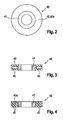
- Fig. 2
- ein als Dämpfungselement modifiziertes Einstellstück, wie es bei dem Kraftstoffinjektor gemäß
Fig. 1 verwendet wird, in Draufsicht und - Fig. 3 und 4
- Querschnitte durch das Einstellstück gemäß
Fig. 2 , bei denen das Dämpfungselement jeweils unterschiedlich ausgebildet ist. - Gleiche Bauteile bzw. Bauteile mit gleicher Funktion sind in den Figuren mit denselben Bezugsziffern versehen.
- In der
Fig. 1 ist der obere, brennraumferne Bereich eines erfindungsgemäßen Kraftstoffinjektors 10 dargestellt, wie er als Common-Rail-Injektor zum Einspritzen von Kraftstoff in einen nicht dargestellten Brennraum einer Brennkraftmaschine dient. Hierbei ist jedem Zylinder der Brennkraftmaschine ein separater Kraftstoffinjektor 10 zugeordnet, und der Systemdruck in dem Kraftstoffeinspritzsystem beträgt mehr als 1.500bar, vorzugsweise mehr als 2.000bar. - Da derartige Kraftstoffinjektoren aus dem Stand der Technik allgemein bekannt sind, wird im Folgenden der Kraftstoffinjektor 10 nur in soweit beschrieben, als dies für das Verständnis der Erfindung wesentlich ist.
- Der Kraftstoffinjektor 10 weist ein insgesamt hülsenförmiges Ventilgehäuse 11 auf, das insbesondere mehrteilig ausgebildet sein kann, wobei Gehäuseteile 12, 13 des Ventilgehäuses 11 beispielsweise über eine Gewindeverbindung 14 miteinander druckfest verbunden bzw. verschraubt sind. In dem Ventilgehäuse 11 ist ein Aktormodulraum 15 ausgebildet, der der Aufnahme eines Piezoaktors 18 dient. Der in Form eines Piezostapels ausgebildete Piezoaktor 18 ist über nicht dargestellte elektrische Leitungen ansteuerbar, derart, dass sich dessen Länge bei einer Bestromung des Piezoaktors 18 ausdehnt. Der Piezoaktor 18 dient in an sich bekannter Art und Weise zum zumindest mittelbaren betätigen einer Ventilnadel 20, die auf der dem Brennraum zugewandten Seite des Kraftstoffinjektors 10 in dem Ventilgehäuse 11 entsprechend des Doppelpfeils 21 auf- und abbeweglich angeordnet ist. Hierbei wird die Bewegung des Piezoaktors 18 über einen Druckübersetzer 22 auf die Ventilnadel 20 übertragen, die mittels einer Druckfeder 23 bei unbestromtem Piezoaktor 18 in eine Schließstellung gedrückt wird, bei der diese im Ventilgehäuse 11 ausgebildete und nicht dargestellte Einspritzöffnungen verschließt. Die Ventilnadel 20 ist in einem Hochdruckraum 25 angeordnet, in dem der angesprochene Systemdruck herrscht.
- Der Aktormodulraum 15 ist über eine Verbindung 26 mit einer Rücklaufleitung 27 hydraulisch gekoppelt, die zum Abführen insbesondere von Leckageverlusten des Kraftstoffinjektors 10 in ein Kraftstoffrücklaufsystem des Einspritzsystems dient. Hierbei herrscht in der Rücklaufleitung 27 bzw. dem Aktormodulraum 15 bei nicht betätigtem Piezoaktor 18 beispielsweise ein Rücklaufdruck von ungefähr 10bar.
- Das der Ventilnadel 20 zugewandte Ende des Piezoaktors 18 ist über ein Bauteil 28 mit einem Ventilkolben 29 gekoppelt, wobei das Bauteil 28 mittels einer Druckfeder 30 in Richtung der Ventilnadel 20 gedrückt wird. Auf der dem Bauteil 28 gegenüberliegenden Seite des Piezoaktors 18 weist der Piezoaktor 18 einen Aktorfuß 31 auf. Der ringförmige Aktorfuß 31 ist hierbei von der Federkraft einer dem Piezoaktor 18 konzentrisch umgebenden Rohrfeder 33 kraftbeaufschlagt, wobei sich die Rohrfeder 33 auf der dem Aktorfuß 31 gegenüberliegenden Seite an einer Zwischenplatte 34 abstützt. Mittels der Rohrfeder 33 wird der Piezoaktor 18 bzw. der Aktorfuß 31 von der Ventilnadel 20 weggedrückt, das heißt in die der Ventilnadel 20 abgewandten Richtung kraftbeaufschlagt.
- Zur axialen Positionierung des Aktorfußes 31 und somit des Piezoaktors 18 im Ventilgehäuse 11 ist ein Einstellstück 35 vorgesehen. Das Einstellstück 35 ist zwischen dem Piezoaktor 18 bzw. dessen Aktorfuß 31 und einem ortsfesten Gehäuseteil in Form eines Zapfens 36 angeordnet und im Ausführungsbeispiel ringförmig ausgebildet. Über die Höhe bzw. Dicke des Einstellstücks 35 lässt sich somit die axiale Position des Aktorfußes 31, der seinerseits von der Rohrfeder 33 kraftbeaufschlagt ist, einstellen.
- Beim Betätigen bzw. Ansteuern des Piezoaktors 18 zum Auf- und Abbewegen der Ventilnadel 20 verkürzt und dehnt sich der Piezoaktor 18 mit hoher Frequenz. Dies führt zu Druckschwankungen mit Druckspitzen innerhalb des Aktormodulraums 15, die für die Bauteile des Piezoaktor 18 kritisch werden können. Daher ist es erfindungsgemäß vorgesehen, dass innerhalb des Aktormodulraums 15 ein Dämpfungselement 40 zur Reduzierung der hydraulischen Druckspitzen angeordnet ist. Konkret wird vorgeschlagen, dass das Dämpfungselement 40 als Teil des Einstellstücks 35 ausgebildet ist.
- Wie insbesondere aus einer Zusammenschau der
Fig. 1 und2 erkennbar ist, weist das ringförmige Einstellstück 35 einen ersten, radial inneren Bereich 41 auf, der starr ausgebildet ist. Der erste Bereich 41 ist konzentrisch von einem zweiten Bereich 42 umgeben, der kompressible Eigenschaften aufweist. Wesentlich hierbei ist, dass die von der Rohrfeder 33 herrührende (mechanische) Druckkraft auf den Aktorfuß 31 über das Einstellstück 35 lediglich über den starren Bereich 41 auf das Injektorgehäuse 11 übertragen wird. Somit ist der zweite, kompressible Bereich 42 im Aktormodulraum 15 in Längsrichtung des Aktormodulraums 15 frei angeordnet, das heißt, zumindest auf der der Ventilnadel 20 zugewandten Stirnseite, vorzugsweise aber auch auf der der Ventilnadel 20 abgewandten Stirnseite sowie radial von Kraftstoff umspült. - Bei dem in der
Fig. 3 dargestellten Ausführungsbeispiel ist der mit dem ersten Bereich 41 durch eine geeignete Verbindungsart, wie Kleben, Schweißen, Schrumpfen o.ä. verbundene zweite Bereich 42 derart ausgebildet, dass der zweite Bereich 42 eine ringförmige Kammer 45 ausbildet. In der Kammer 45 ist unter einem bestimmten Druck befindliche Luft bzw. Gas angeordnet, wobei die Wand 46 des zweiten Bereichs 42 ihrerseits eine gewisse Flexibilität aufweist, um Druckschwankungen auf die Kammer 45 zu übertragen. Wesentlich ist auch, dass durch eine entsprechende Ausbildung der Wand 46 (Material/Wandstärke) bzw. der Höhe des Drucks in der Kammer 45 eine Kompression des zweiten Bereichs 42 im wesentlichen Ausmaß erst dann auftritt, wenn der in dem Aktormodulraum 15 herrschende Druck größer ist als insbesondere der Rücklaufdruck im Einspritzsystem. Dadurch können die kompressiblen Eigenschaften des zweiten Bereichs 42 zur Dämpfung der angesprochenen Druckspitzen ausgenutzt werden. - In einer nicht dargestellten Variante der
Fig. 3 ist es selbstverständlich auch möglich, anstelle einer einzigen Kammer 45 mehrere, voneinander getrennte Kammern 45 auszubilden bzw. anzuordnen. - Bei dem in der
Fig. 4 dargestellten Ausführungsbeispiel ist der zweite Bereich 42a in Form eines geschäumten Materials ausgebildet, in dem Luft- bzw. Gaseinschlüsse 47 ausgebildet sind. Auch die Luft- bzw. Gaseinschlüsse 47 bewirken eine Kompressibilität des zweiten Bereichs 42 zur Aufnahme von hydraulischen Druckspitzen. - Ergänzend wird erwähnt, dass das Dämpfungselement 40 auch in Form eines sogenannten Wills Rings ® ausgebildet sein kann. Ein derartiger, aus Metall gefertigter Ring weist ebenfalls kompressible Eigenschaften aus.
- Der soweit beschriebene Kraftstoffinjektor 10 kann in vielfältiger Art und Weise abgewandelt bzw. modifiziert werden, ohne vom Erfindungsgedanken abzuweichen. So ist es beispielsweise denkbar, das Dämpfungselement 40 an einer anderen Stelle im Aktormodulraum 15 anzuordnen. Dadurch wird gegebenenfalls jedoch ein gegenüber den Ausführungsbeispielen erhöhter Bauraum erforderlich.
Claims (10)
- Kraftstoffinjektor (10), insbesondere Common-Rail-Injektor, mit einem Injektorgehäuse (11), in dem eine auf- und abbewegliche Ventilnadel (20) angeordnet ist, sowie einem Piezoaktor (18) zum zumindest mittelbaren Betätigen der Ventilnadel (20), wobei der Piezoaktor (20) in einem mit Kraftstoff befüllten Aktormodulraum (15) angeordnet ist, der mit einem Kraftstoffrücklauf (27) gekoppelt ist, und wobei der Piezoaktor (18) in Richtung der der Ventilnadel (20) abgewandten Seite kraftbeaufschlagt ist,
dadurch gekennzeichnet,
dass in dem Aktormodulraum (15) ein kompressibles Dämpfungselement (40) zur Reduzierung von hydraulischen Druckspitzen angeordnet ist. - Kraftstoffinjektor nach Anspruch 1,
dadurch gekennzeichnet,
dass das Dämpfungselement (40) zwischen dem Piezoaktor (18) und dem Ventilgehäuse (11) auf der der Ventilnadel (20) abgewandten Seite des Piezoaktors (18) angeordnet ist. - Kraftstoffinjektor nach Anspruch 2,
dadurch gekennzeichnet,
dass das Dämpfungselement (40) Teil eines Einstellstücks (35) zur Einstellung der axialen Position des Piezoaktors (18) im Aktormodulraum (15) ist. - Kraftstoffinjektor nach Anspruch 3,
dadurch gekennzeichnet,
dass das Einstellstück (35) einen kompressiblen Bereich (42; 42a) und einen starren Bereich (41) aufweist, wobei der kompressible Bereich (42; 42a) mit Kraftstoff in Berührung steht. - Kraftstoffinjektor nach Anspruch 4,
dadurch gekennzeichnet,
dass der kompressible Bereich (42; 42a) den starren Bereich (41), insbesondere in Form eines Ringes konzentrisch umgibt. - Kraftstoffinjektor nach Anspruch 5,
dadurch gekennzeichnet,
dass der kompressible Bereich (42) wenigstens eine mit Gas oder Luft befüllte Kammer (45) aufweist. - Kraftstoffinjektor nach Anspruch 5,
dadurch gekennzeichnet,
dass der kompressible Bereich (42a) als ein Gas- oder Lufteinschlüsse aufweisender, geschäumter Bereich ist. - Kraftstoffinjektor nach einem der Ansprüche 2 bis 5,
dadurch gekennzeichnet,
dass das Dämpfungselement (40) ein Wills Ring® ist. - Kraftstoffinjektor nach einem der Ansprüche 5 bis 8,
dadurch gekennzeichnet,
dass der starre Bereich (41) über einen in Wirkverbindung mit einer Feder (35) angeordneten Aktorfuß (31) kraftbeaufschlagt beaufschlagt. - Kraftstoffinjektor nach einem der Ansprüche 1 bis 9,
dadurch gekennzeichnet,
dass das Dämpfungselement (40) im Wesentlichen erst bei einem Druck oberhalb eines Rücklaufdrucks kompressibel ist.
Applications Claiming Priority (1)
| Application Number | Priority Date | Filing Date | Title |
|---|---|---|---|
| DE102010042622A DE102010042622A1 (de) | 2010-10-19 | 2010-10-19 | Kraftstoffinjektor, inbesondere Common-Rail-Injektor |
Publications (4)
| Publication Number | Publication Date |
|---|---|
| EP2444649A2 true EP2444649A2 (de) | 2012-04-25 |
| EP2444649A3 EP2444649A3 (de) | 2013-02-27 |
| EP2444649B1 EP2444649B1 (de) | 2020-04-01 |
| EP2444649B8 EP2444649B8 (de) | 2020-06-10 |
Family
ID=44651406
Family Applications (1)
| Application Number | Title | Priority Date | Filing Date |
|---|---|---|---|
| EP11181816.7A Active EP2444649B8 (de) | 2010-10-19 | 2011-09-19 | Kraftstoffinjektor, insbesondere common-rail-injektor |
Country Status (2)
| Country | Link |
|---|---|
| EP (1) | EP2444649B8 (de) |
| DE (1) | DE102010042622A1 (de) |
Families Citing this family (1)
| Publication number | Priority date | Publication date | Assignee | Title |
|---|---|---|---|---|
| DE102016209546A1 (de) * | 2016-06-01 | 2017-12-07 | Robert Bosch Gmbh | Kraftstoffeinspritzventil |
Citations (1)
| Publication number | Priority date | Publication date | Assignee | Title |
|---|---|---|---|---|
| DE102006026381A1 (de) | 2006-06-07 | 2007-12-13 | Robert Bosch Gmbh | Kraftstoffinjektor mit Druckübersetzer und niederdruckseitig angeordnetem Piezosteller |
Family Cites Families (5)
| Publication number | Priority date | Publication date | Assignee | Title |
|---|---|---|---|---|
| DE19727992C2 (de) * | 1997-07-01 | 1999-05-20 | Siemens Ag | Ausgleichselement zur Kompensation temperaturbedingter Längenänderungen von elektromechanischen Stellsystemen |
| DE10057495B4 (de) * | 2000-11-20 | 2005-08-04 | Siemens Ag | Injektorgehäuse mit einer Aktoreinheit |
| DE102006019736A1 (de) * | 2006-04-28 | 2007-10-31 | Robert Bosch Gmbh | Kraftstoffinjektor |
| DE102006021945A1 (de) * | 2006-05-11 | 2007-11-15 | Robert Bosch Gmbh | Piezoelektrischer Aktor und Injektor mit einem piezoelektrischen Aktor für eine Brennkraftmaschine |
| DE102006035982A1 (de) * | 2006-08-02 | 2008-02-07 | Robert Bosch Gmbh | Injektor |
-
2010
- 2010-10-19 DE DE102010042622A patent/DE102010042622A1/de not_active Withdrawn
-
2011
- 2011-09-19 EP EP11181816.7A patent/EP2444649B8/de active Active
Patent Citations (1)
| Publication number | Priority date | Publication date | Assignee | Title |
|---|---|---|---|---|
| DE102006026381A1 (de) | 2006-06-07 | 2007-12-13 | Robert Bosch Gmbh | Kraftstoffinjektor mit Druckübersetzer und niederdruckseitig angeordnetem Piezosteller |
Also Published As
| Publication number | Publication date |
|---|---|
| DE102010042622A1 (de) | 2012-04-19 |
| EP2444649B1 (de) | 2020-04-01 |
| EP2444649A3 (de) | 2013-02-27 |
| EP2444649B8 (de) | 2020-06-10 |
Similar Documents
| Publication | Publication Date | Title |
|---|---|---|
| EP1693564B1 (de) | Kraftstoffinjektor mit direkter Nadelsteuerung für eine Brennkraftmaschine | |
| DE102005009147A1 (de) | Kraftstoffinjektor für Verbrennungskraftmaschinen | |
| WO2002046602A1 (de) | Kraftstoffeinspritzsystem für brennkraftmaschinen | |
| EP1688611A2 (de) | Kraftstoffinjektor mit direkter Nadelsteuerung für eine Brennkraftmaschine | |
| EP2510215B1 (de) | Kraftstoffinjektor | |
| EP2150696B1 (de) | Injektor für eine kraftstoffeinspritzanlage | |
| EP1692392B1 (de) | Kraftstoffinjektor mit direkter nadelsteuerung | |
| EP2444649B1 (de) | Kraftstoffinjektor, insbesondere common-rail-injektor | |
| EP1763628A1 (de) | Einspritzdüse | |
| EP2898212B1 (de) | Brennstoffeinspritzventil | |
| EP1999363B1 (de) | Kraftstoffeinspritzventile für brennkraftmaschinen | |
| EP2891789B1 (de) | Kraftstoffinjektor und Verfahren zum Herstellen eines Kraftstoffinjektors | |
| EP1873393A1 (de) | Injektor | |
| EP2930344B1 (de) | Kraftstoffinjektor | |
| EP2920452B1 (de) | Injektor | |
| EP2439398B1 (de) | Brennstoffeinspritzventil | |
| DE102004044811A1 (de) | Steuerventil einer Einspritzdüse | |
| DE102010029123A1 (de) | Kraftstoffinjektor mit hydraulischer Kopplereinheit | |
| DE102006036782B4 (de) | Injektor | |
| EP2930345B1 (de) | Kraftstoffinjektor | |
| DE102011086335A1 (de) | Brennstoffeinspritzventil | |
| DE102005038596A1 (de) | Kraftstoffinjektor für eine selbstzündende Verbrennungskraftmaschine | |
| DE102006014768A1 (de) | Piezoelektrischer Aktor mit ringförmigem Aktorstapel und Injektor für eine Brennkraftmaschine mit ringförmigem Piezoaktor | |
| DE102006035982A1 (de) | Injektor | |
| DE102007014359A1 (de) | Injektor für eine Kraftstoffeinspritzanlage |
Legal Events
| Date | Code | Title | Description |
|---|---|---|---|
| AK | Designated contracting states |
Kind code of ref document: A2 Designated state(s): AL AT BE BG CH CY CZ DE DK EE ES FI FR GB GR HR HU IE IS IT LI LT LU LV MC MK MT NL NO PL PT RO RS SE SI SK SM TR |
|
| AX | Request for extension of the european patent |
Extension state: BA ME |
|
| PUAI | Public reference made under article 153(3) epc to a published international application that has entered the european phase |
Free format text: ORIGINAL CODE: 0009012 |
|
| PUAL | Search report despatched |
Free format text: ORIGINAL CODE: 0009013 |
|
| AK | Designated contracting states |
Kind code of ref document: A3 Designated state(s): AL AT BE BG CH CY CZ DE DK EE ES FI FR GB GR HR HU IE IS IT LI LT LU LV MC MK MT NL NO PL PT RO RS SE SI SK SM TR |
|
| AX | Request for extension of the european patent |
Extension state: BA ME |
|
| RIC1 | Information provided on ipc code assigned before grant |
Ipc: F02M 63/00 20060101ALI20130123BHEP Ipc: F02M 47/02 20060101AFI20130123BHEP |
|
| 17P | Request for examination filed |
Effective date: 20130827 |
|
| RBV | Designated contracting states (corrected) |
Designated state(s): AL AT BE BG CH CY CZ DE DK EE ES FI FR GB GR HR HU IE IS IT LI LT LU LV MC MK MT NL NO PL PT RO RS SE SI SK SM TR |
|
| 17Q | First examination report despatched |
Effective date: 20160630 |
|
| STAA | Information on the status of an ep patent application or granted ep patent |
Free format text: STATUS: EXAMINATION IS IN PROGRESS |
|
| GRAP | Despatch of communication of intention to grant a patent |
Free format text: ORIGINAL CODE: EPIDOSNIGR1 |
|
| STAA | Information on the status of an ep patent application or granted ep patent |
Free format text: STATUS: GRANT OF PATENT IS INTENDED |
|
| INTG | Intention to grant announced |
Effective date: 20191015 |
|
| GRAS | Grant fee paid |
Free format text: ORIGINAL CODE: EPIDOSNIGR3 |
|
| GRAA | (expected) grant |
Free format text: ORIGINAL CODE: 0009210 |
|
| STAA | Information on the status of an ep patent application or granted ep patent |
Free format text: STATUS: THE PATENT HAS BEEN GRANTED |
|
| AK | Designated contracting states |
Kind code of ref document: B1 Designated state(s): AL AT BE BG CH CY CZ DE DK EE ES FI FR GB GR HR HU IE IS IT LI LT LU LV MC MK MT NL NO PL PT RO RS SE SI SK SM TR |
|
| REG | Reference to a national code |
Ref country code: GB Ref legal event code: FG4D Free format text: NOT ENGLISH |
|
| REG | Reference to a national code |
Ref country code: AT Ref legal event code: REF Ref document number: 1251655 Country of ref document: AT Kind code of ref document: T Effective date: 20200415 Ref country code: CH Ref legal event code: EP |
|
| REG | Reference to a national code |
Ref country code: DE Ref legal event code: R096 Ref document number: 502011016576 Country of ref document: DE |
|
| RAP2 | Party data changed (patent owner data changed or rights of a patent transferred) |
Owner name: ROBERT BOSCH GMBH |
|
| REG | Reference to a national code |
Ref country code: IE Ref legal event code: FG4D Free format text: LANGUAGE OF EP DOCUMENT: GERMAN |
|
| REG | Reference to a national code |
Ref country code: CH Ref legal event code: PK Free format text: BERICHTIGUNG B8 |
|
| PG25 | Lapsed in a contracting state [announced via postgrant information from national office to epo] |
Ref country code: BG Free format text: LAPSE BECAUSE OF FAILURE TO SUBMIT A TRANSLATION OF THE DESCRIPTION OR TO PAY THE FEE WITHIN THE PRESCRIBED TIME-LIMIT Effective date: 20200701 |
|
| REG | Reference to a national code |
Ref country code: NL Ref legal event code: MP Effective date: 20200401 |
|
| REG | Reference to a national code |
Ref country code: LT Ref legal event code: MG4D |
|
| PG25 | Lapsed in a contracting state [announced via postgrant information from national office to epo] |
Ref country code: NL Free format text: LAPSE BECAUSE OF FAILURE TO SUBMIT A TRANSLATION OF THE DESCRIPTION OR TO PAY THE FEE WITHIN THE PRESCRIBED TIME-LIMIT Effective date: 20200401 Ref country code: PT Free format text: LAPSE BECAUSE OF FAILURE TO SUBMIT A TRANSLATION OF THE DESCRIPTION OR TO PAY THE FEE WITHIN THE PRESCRIBED TIME-LIMIT Effective date: 20200817 Ref country code: LT Free format text: LAPSE BECAUSE OF FAILURE TO SUBMIT A TRANSLATION OF THE DESCRIPTION OR TO PAY THE FEE WITHIN THE PRESCRIBED TIME-LIMIT Effective date: 20200401 Ref country code: IS Free format text: LAPSE BECAUSE OF FAILURE TO SUBMIT A TRANSLATION OF THE DESCRIPTION OR TO PAY THE FEE WITHIN THE PRESCRIBED TIME-LIMIT Effective date: 20200801 Ref country code: SE Free format text: LAPSE BECAUSE OF FAILURE TO SUBMIT A TRANSLATION OF THE DESCRIPTION OR TO PAY THE FEE WITHIN THE PRESCRIBED TIME-LIMIT Effective date: 20200401 Ref country code: NO Free format text: LAPSE BECAUSE OF FAILURE TO SUBMIT A TRANSLATION OF THE DESCRIPTION OR TO PAY THE FEE WITHIN THE PRESCRIBED TIME-LIMIT Effective date: 20200701 Ref country code: FI Free format text: LAPSE BECAUSE OF FAILURE TO SUBMIT A TRANSLATION OF THE DESCRIPTION OR TO PAY THE FEE WITHIN THE PRESCRIBED TIME-LIMIT Effective date: 20200401 Ref country code: GR Free format text: LAPSE BECAUSE OF FAILURE TO SUBMIT A TRANSLATION OF THE DESCRIPTION OR TO PAY THE FEE WITHIN THE PRESCRIBED TIME-LIMIT Effective date: 20200702 |
|
| PG25 | Lapsed in a contracting state [announced via postgrant information from national office to epo] |
Ref country code: HR Free format text: LAPSE BECAUSE OF FAILURE TO SUBMIT A TRANSLATION OF THE DESCRIPTION OR TO PAY THE FEE WITHIN THE PRESCRIBED TIME-LIMIT Effective date: 20200401 Ref country code: RS Free format text: LAPSE BECAUSE OF FAILURE TO SUBMIT A TRANSLATION OF THE DESCRIPTION OR TO PAY THE FEE WITHIN THE PRESCRIBED TIME-LIMIT Effective date: 20200401 Ref country code: LV Free format text: LAPSE BECAUSE OF FAILURE TO SUBMIT A TRANSLATION OF THE DESCRIPTION OR TO PAY THE FEE WITHIN THE PRESCRIBED TIME-LIMIT Effective date: 20200401 |
|
| PG25 | Lapsed in a contracting state [announced via postgrant information from national office to epo] |
Ref country code: AL Free format text: LAPSE BECAUSE OF FAILURE TO SUBMIT A TRANSLATION OF THE DESCRIPTION OR TO PAY THE FEE WITHIN THE PRESCRIBED TIME-LIMIT Effective date: 20200401 |
|
| REG | Reference to a national code |
Ref country code: DE Ref legal event code: R097 Ref document number: 502011016576 Country of ref document: DE |
|
| PG25 | Lapsed in a contracting state [announced via postgrant information from national office to epo] |
Ref country code: CZ Free format text: LAPSE BECAUSE OF FAILURE TO SUBMIT A TRANSLATION OF THE DESCRIPTION OR TO PAY THE FEE WITHIN THE PRESCRIBED TIME-LIMIT Effective date: 20200401 Ref country code: RO Free format text: LAPSE BECAUSE OF FAILURE TO SUBMIT A TRANSLATION OF THE DESCRIPTION OR TO PAY THE FEE WITHIN THE PRESCRIBED TIME-LIMIT Effective date: 20200401 Ref country code: ES Free format text: LAPSE BECAUSE OF FAILURE TO SUBMIT A TRANSLATION OF THE DESCRIPTION OR TO PAY THE FEE WITHIN THE PRESCRIBED TIME-LIMIT Effective date: 20200401 Ref country code: IT Free format text: LAPSE BECAUSE OF FAILURE TO SUBMIT A TRANSLATION OF THE DESCRIPTION OR TO PAY THE FEE WITHIN THE PRESCRIBED TIME-LIMIT Effective date: 20200401 Ref country code: SM Free format text: LAPSE BECAUSE OF FAILURE TO SUBMIT A TRANSLATION OF THE DESCRIPTION OR TO PAY THE FEE WITHIN THE PRESCRIBED TIME-LIMIT Effective date: 20200401 Ref country code: DK Free format text: LAPSE BECAUSE OF FAILURE TO SUBMIT A TRANSLATION OF THE DESCRIPTION OR TO PAY THE FEE WITHIN THE PRESCRIBED TIME-LIMIT Effective date: 20200401 Ref country code: EE Free format text: LAPSE BECAUSE OF FAILURE TO SUBMIT A TRANSLATION OF THE DESCRIPTION OR TO PAY THE FEE WITHIN THE PRESCRIBED TIME-LIMIT Effective date: 20200401 |
|
| PLBE | No opposition filed within time limit |
Free format text: ORIGINAL CODE: 0009261 |
|
| STAA | Information on the status of an ep patent application or granted ep patent |
Free format text: STATUS: NO OPPOSITION FILED WITHIN TIME LIMIT |
|
| PG25 | Lapsed in a contracting state [announced via postgrant information from national office to epo] |
Ref country code: SK Free format text: LAPSE BECAUSE OF FAILURE TO SUBMIT A TRANSLATION OF THE DESCRIPTION OR TO PAY THE FEE WITHIN THE PRESCRIBED TIME-LIMIT Effective date: 20200401 Ref country code: PL Free format text: LAPSE BECAUSE OF FAILURE TO SUBMIT A TRANSLATION OF THE DESCRIPTION OR TO PAY THE FEE WITHIN THE PRESCRIBED TIME-LIMIT Effective date: 20200401 |
|
| 26N | No opposition filed |
Effective date: 20210112 |
|
| REG | Reference to a national code |
Ref country code: DE Ref legal event code: R119 Ref document number: 502011016576 Country of ref document: DE |
|
| PG25 | Lapsed in a contracting state [announced via postgrant information from national office to epo] |
Ref country code: MC Free format text: LAPSE BECAUSE OF FAILURE TO SUBMIT A TRANSLATION OF THE DESCRIPTION OR TO PAY THE FEE WITHIN THE PRESCRIBED TIME-LIMIT Effective date: 20200401 |
|
| REG | Reference to a national code |
Ref country code: CH Ref legal event code: PL |
|
| GBPC | Gb: european patent ceased through non-payment of renewal fee |
Effective date: 20200919 |
|
| PG25 | Lapsed in a contracting state [announced via postgrant information from national office to epo] |
Ref country code: SI Free format text: LAPSE BECAUSE OF FAILURE TO SUBMIT A TRANSLATION OF THE DESCRIPTION OR TO PAY THE FEE WITHIN THE PRESCRIBED TIME-LIMIT Effective date: 20200401 |
|
| REG | Reference to a national code |
Ref country code: BE Ref legal event code: MM Effective date: 20200930 |
|
| PG25 | Lapsed in a contracting state [announced via postgrant information from national office to epo] |
Ref country code: LU Free format text: LAPSE BECAUSE OF NON-PAYMENT OF DUE FEES Effective date: 20200919 |
|
| PG25 | Lapsed in a contracting state [announced via postgrant information from national office to epo] |
Ref country code: FR Free format text: LAPSE BECAUSE OF NON-PAYMENT OF DUE FEES Effective date: 20200930 Ref country code: DE Free format text: LAPSE BECAUSE OF NON-PAYMENT OF DUE FEES Effective date: 20210401 |
|
| PG25 | Lapsed in a contracting state [announced via postgrant information from national office to epo] |
Ref country code: BE Free format text: LAPSE BECAUSE OF NON-PAYMENT OF DUE FEES Effective date: 20200930 Ref country code: CH Free format text: LAPSE BECAUSE OF NON-PAYMENT OF DUE FEES Effective date: 20200930 Ref country code: IE Free format text: LAPSE BECAUSE OF NON-PAYMENT OF DUE FEES Effective date: 20200919 Ref country code: GB Free format text: LAPSE BECAUSE OF NON-PAYMENT OF DUE FEES Effective date: 20200919 Ref country code: LI Free format text: LAPSE BECAUSE OF NON-PAYMENT OF DUE FEES Effective date: 20200930 |
|
| REG | Reference to a national code |
Ref country code: AT Ref legal event code: MM01 Ref document number: 1251655 Country of ref document: AT Kind code of ref document: T Effective date: 20200919 |
|
| PG25 | Lapsed in a contracting state [announced via postgrant information from national office to epo] |
Ref country code: AT Free format text: LAPSE BECAUSE OF NON-PAYMENT OF DUE FEES Effective date: 20200919 |
|
| PG25 | Lapsed in a contracting state [announced via postgrant information from national office to epo] |
Ref country code: TR Free format text: LAPSE BECAUSE OF FAILURE TO SUBMIT A TRANSLATION OF THE DESCRIPTION OR TO PAY THE FEE WITHIN THE PRESCRIBED TIME-LIMIT Effective date: 20200401 Ref country code: MT Free format text: LAPSE BECAUSE OF FAILURE TO SUBMIT A TRANSLATION OF THE DESCRIPTION OR TO PAY THE FEE WITHIN THE PRESCRIBED TIME-LIMIT Effective date: 20200401 Ref country code: CY Free format text: LAPSE BECAUSE OF FAILURE TO SUBMIT A TRANSLATION OF THE DESCRIPTION OR TO PAY THE FEE WITHIN THE PRESCRIBED TIME-LIMIT Effective date: 20200401 |
|
| PG25 | Lapsed in a contracting state [announced via postgrant information from national office to epo] |
Ref country code: MK Free format text: LAPSE BECAUSE OF FAILURE TO SUBMIT A TRANSLATION OF THE DESCRIPTION OR TO PAY THE FEE WITHIN THE PRESCRIBED TIME-LIMIT Effective date: 20200401 |