EP2444508A1 - FERRITIC Cr-STEEL FOR HEAT-RESISTANT PRECISION COMPONENT AND METHOD FOR PRODUCING SAME, AND HEAT-RESISTANT PRECISION COMPONENT AND METHOD FOR PRODUCING SAME - Google Patents
FERRITIC Cr-STEEL FOR HEAT-RESISTANT PRECISION COMPONENT AND METHOD FOR PRODUCING SAME, AND HEAT-RESISTANT PRECISION COMPONENT AND METHOD FOR PRODUCING SAME Download PDFInfo
- Publication number
- EP2444508A1 EP2444508A1 EP10789374A EP10789374A EP2444508A1 EP 2444508 A1 EP2444508 A1 EP 2444508A1 EP 10789374 A EP10789374 A EP 10789374A EP 10789374 A EP10789374 A EP 10789374A EP 2444508 A1 EP2444508 A1 EP 2444508A1
- Authority
- EP
- European Patent Office
- Prior art keywords
- steel
- ferritic
- heat
- precision component
- resistant precision
- Prior art date
- Legal status (The legal status is an assumption and is not a legal conclusion. Google has not performed a legal analysis and makes no representation as to the accuracy of the status listed.)
- Withdrawn
Links
Images
Classifications
-
- C—CHEMISTRY; METALLURGY
- C21—METALLURGY OF IRON
- C21D—MODIFYING THE PHYSICAL STRUCTURE OF FERROUS METALS; GENERAL DEVICES FOR HEAT TREATMENT OF FERROUS OR NON-FERROUS METALS OR ALLOYS; MAKING METAL MALLEABLE, e.g. BY DECARBURISATION OR TEMPERING
- C21D6/00—Heat treatment of ferrous alloys
- C21D6/004—Heat treatment of ferrous alloys containing Cr and Ni
-
- C—CHEMISTRY; METALLURGY
- C22—METALLURGY; FERROUS OR NON-FERROUS ALLOYS; TREATMENT OF ALLOYS OR NON-FERROUS METALS
- C22C—ALLOYS
- C22C38/00—Ferrous alloys, e.g. steel alloys
- C22C38/001—Ferrous alloys, e.g. steel alloys containing N
-
- C—CHEMISTRY; METALLURGY
- C22—METALLURGY; FERROUS OR NON-FERROUS ALLOYS; TREATMENT OF ALLOYS OR NON-FERROUS METALS
- C22C—ALLOYS
- C22C38/00—Ferrous alloys, e.g. steel alloys
- C22C38/02—Ferrous alloys, e.g. steel alloys containing silicon
-
- C—CHEMISTRY; METALLURGY
- C22—METALLURGY; FERROUS OR NON-FERROUS ALLOYS; TREATMENT OF ALLOYS OR NON-FERROUS METALS
- C22C—ALLOYS
- C22C38/00—Ferrous alloys, e.g. steel alloys
- C22C38/04—Ferrous alloys, e.g. steel alloys containing manganese
-
- C—CHEMISTRY; METALLURGY
- C22—METALLURGY; FERROUS OR NON-FERROUS ALLOYS; TREATMENT OF ALLOYS OR NON-FERROUS METALS
- C22C—ALLOYS
- C22C38/00—Ferrous alloys, e.g. steel alloys
- C22C38/18—Ferrous alloys, e.g. steel alloys containing chromium
- C22C38/40—Ferrous alloys, e.g. steel alloys containing chromium with nickel
- C22C38/44—Ferrous alloys, e.g. steel alloys containing chromium with nickel with molybdenum or tungsten
-
- C—CHEMISTRY; METALLURGY
- C22—METALLURGY; FERROUS OR NON-FERROUS ALLOYS; TREATMENT OF ALLOYS OR NON-FERROUS METALS
- C22C—ALLOYS
- C22C38/00—Ferrous alloys, e.g. steel alloys
- C22C38/18—Ferrous alloys, e.g. steel alloys containing chromium
- C22C38/40—Ferrous alloys, e.g. steel alloys containing chromium with nickel
- C22C38/46—Ferrous alloys, e.g. steel alloys containing chromium with nickel with vanadium
-
- C—CHEMISTRY; METALLURGY
- C22—METALLURGY; FERROUS OR NON-FERROUS ALLOYS; TREATMENT OF ALLOYS OR NON-FERROUS METALS
- C22C—ALLOYS
- C22C38/00—Ferrous alloys, e.g. steel alloys
- C22C38/18—Ferrous alloys, e.g. steel alloys containing chromium
- C22C38/40—Ferrous alloys, e.g. steel alloys containing chromium with nickel
- C22C38/48—Ferrous alloys, e.g. steel alloys containing chromium with nickel with niobium or tantalum
-
- C—CHEMISTRY; METALLURGY
- C22—METALLURGY; FERROUS OR NON-FERROUS ALLOYS; TREATMENT OF ALLOYS OR NON-FERROUS METALS
- C22C—ALLOYS
- C22C38/00—Ferrous alloys, e.g. steel alloys
- C22C38/18—Ferrous alloys, e.g. steel alloys containing chromium
- C22C38/40—Ferrous alloys, e.g. steel alloys containing chromium with nickel
- C22C38/52—Ferrous alloys, e.g. steel alloys containing chromium with nickel with cobalt
-
- C—CHEMISTRY; METALLURGY
- C22—METALLURGY; FERROUS OR NON-FERROUS ALLOYS; TREATMENT OF ALLOYS OR NON-FERROUS METALS
- C22C—ALLOYS
- C22C38/00—Ferrous alloys, e.g. steel alloys
- C22C38/18—Ferrous alloys, e.g. steel alloys containing chromium
- C22C38/40—Ferrous alloys, e.g. steel alloys containing chromium with nickel
- C22C38/54—Ferrous alloys, e.g. steel alloys containing chromium with nickel with boron
-
- C—CHEMISTRY; METALLURGY
- C21—METALLURGY OF IRON
- C21D—MODIFYING THE PHYSICAL STRUCTURE OF FERROUS METALS; GENERAL DEVICES FOR HEAT TREATMENT OF FERROUS OR NON-FERROUS METALS OR ALLOYS; MAKING METAL MALLEABLE, e.g. BY DECARBURISATION OR TEMPERING
- C21D2211/00—Microstructure comprising significant phases
- C21D2211/005—Ferrite
Definitions
- the present invention relates to ferritic Cr-steel used as material of precision components that have heat resistance.
- Ferritic Cr-steel also called ferritic high Cr-steel
- heat-resistant precision components such as the rotors, discs, and blades of machines such as steam turbines and gas turbines used under high temperature, because large thermal expansion coefficient differences cause positional misalignment relative to the other components.
- Patent Document 1 In face of the recent demand for use of turbines under high temperatures above 650°C, a Ni-based superalloy has been proposed as material of heat-resistant precision components, as described in Patent Document 1.
- ferritic Cr-steel which undergoes small dimensional changes by thermal expansion, has low high-temperature strength, and undergoes creep deformation and changes the shape of the precision component.
- the physical properties of the Ni-based superalloy do not allow the thermal expansion coefficient to be kept at values below that of the ferritic Cr-steel. In fact, further improvement in heat resistance tends to increase the thermal expansion coefficient.
- the present invention has been made under these circumstances, and it is an object of the present invention to provide a ferritic Cr-steel for a heat-resistant precision component and a producing process thereof, and a heat-resistant precision component and a producing process thereof, with which heat resistance can be improved while providing low thermal expansion properties.
- the present invention provides a ferritic Cr-steel for a heat-resistant precision component, characterized in that the ferritic Cr-steel is of a chemical composition that mainly includes, in % by mass, Cr: 13 to 30%, Ni: 1 ⁇ 10 -1 to 2.5%, C: 1 ⁇ 10 -3 to 1 ⁇ 10 -1 %, and N: 1 ⁇ 10 -3 to 1 ⁇ 10 -1 %, wherein the ferritic Cr-steel allows for inclusion of an additional component and unavoidable impurities, includes Fe as the remaining part, and forms a ferrite phase.
- Ni be added in an amount that satisfies the relationship Ni > 10(C + N), where Ni, C, and N each represent the amount of each component added (in % by mass), when C is added in 1 ⁇ 10 -2 % by mass or more and/or Ni is added in 1 ⁇ 10 -2 % by mass or more.
- ferritic Cr-steel it is preferable in the ferritic Cr-steel for a heat-resistant precision component that the ferrite phase be 70 volume% or more.
- the additional component be one or more of the following in % by mass, Mo: 5 ⁇ 10 -1 to 5%, W: 5 ⁇ 10 -1 to 1 ⁇ 10%, V: 5 ⁇ 10 -2 to 4 ⁇ 10 -1 %, Nb: 1 ⁇ 10 -2 to 1 ⁇ 10 -1 %, Co: 1 ⁇ 10 -1 to 1 ⁇ 10%, and B: 2 ⁇ 10 -3 to 4 ⁇ 10 -3 %, and that at least one of carbide, nitride, and intermetallic compound be precipitated in crystal grains.
- Mo and W be added in amounts that satisfy the relationship Mo + 0.5W ⁇ 3.0% by mass, where Mo and W each represent the amount of each component added (in % by mass).
- the present invention also provides a ferritic Cr-steel for use in a heat-resistant precision component and that contains Cr in an amount of from 13% by mass to 30% by mass,
- the ferritic Cr-steel has a thermal expansion coefficient of 15 ⁇ 10 -6 or less in a temperature range of from room temperature to 800°C, and a minimum creep rate of 1 ⁇ 10 -4 /h or less at 700°C under stress of 100 MPa.
- the present invention also provides a process for producing a ferritic Cr-steel for a heat-resistant precision component, the process including hot working the ferritic Cr-steel of the foregoing chemical composition in a temperature range of 850 to 1,200°C, forming the ferritic Cr-steel into a predetermined shape, subjecting the steel to an annealing treatment in a temperature range of 1,000 to 1,250°C, and cooling the steel to 400°C or lower at a cooling rate of 100°C/min or higher.
- the present invention also provides a heat-resistant precision component formed from the ferritic Cr-steel for a heat-resistant precision component.
- the heat-resistant precision component may be any one of a rotor, a disc, and a blade of a turbine.
- the present invention also provides a process for producing a heat-resistant precision component, the process including hot working the ferritic Cr-steel of the foregoing chemical composition in a temperature range of 850 to 1,200°C, forming the ferritic Cr-steel into a component shape, subjecting the steel to an annealing treatment in a temperature range of 1,000 to 1,250°C, and cooling the steel to 400°C or less at a cooling rate of 100°C/min or higher.
- the ferritic Cr-steel for a heat-resistant precision component and the producing process thereof, and the heat-resistant precision component and the producing process thereof of the present invention realize a heat-resistant precision component for mechanical structures, as represented by turbines, used under high temperature.
- the heat-resistant precision component has high heat resistance (creep strength) while maintaining optimum low thermal expansion properties.
- the ferritic Cr-steel for a heat-resistant precision component of the present invention is a material used for components of mechanical structures such as turbines, and that has excellent high temperature strength, heat resistance, oxidation resistance, and high toughness even at high temperatures above 650°C (here and below, the temperature is represented in units of 50°C), and that can withstand use under high temperature and high pressure for extended time periods while undergoing only a limited decrease in strength.
- the ferritic Cr-steel for a heat-resistant precision component is produced by hot working a ferritic Cr-steel ingot in a temperature range of 850 to 1,200°C and forming the ferritic Cr-steel into a predetermined shape, and then subjecting the steel to an annealing treatment in a temperature range of 1,000 to 1,250°C, and cooling the steel to 400°C or less at a cooling rate of 100°C/min or higher.
- the hot working temperature such as in hot forging is 850 to 1,200°C, preferably 950 to 1,150°C, more preferably 1,000 to 1,100°C. Above the upper limit temperature, an abrupt decrease in ductility may occur. Below the lower limit temperature, deformation resistance increases, which may lead to processing defects such as cracking.
- the temperature of the annealing treatment is 1,000 to 1,250°C, preferably 1,000 to 1,200°C, more preferably 1,050 to 1,200°C. Above the upper limit temperature, serious coarsening of crystal grains may occur, which can be detrimental to various properties of the steel, including toughness, ductility, and weldability. Below the lower limit temperature, it may not be possible to completely melt the steel and to exhibit a sufficient strength.
- Temperatures of 400°C and higher may cause precipitation of a second phase in the process of cooling from the annealing temperature, because of the fast precipitation rate of second-phase compounds such as carbides, nitrides, and intermetallic compounds.
- the cooling rate of the cooling to 400°C or less following the annealing treatment is 100°C/min or higher, preferably 120°C/min or higher, more preferably 150°C/min or higher.
- a coarse second phase may precipitate at the crystal grain boundary during the cooling process, and it becomes difficult to disperse and precipitate a fine second phase in the crystal grains. In this case, sufficient strength may not be developed because of the failure to effectively control the precipitation state of the second phase for strength improvement.
- the ferritic Cr-steel for a heat-resistant precision component produced as above has a linear expansion coefficient of 15 ⁇ 10 -6 or less in a temperature range of from room temperature to 850°C. Above the upper limit, the amounts of thermal expansion and contraction at the start-up and stopping of a turbine increase, and it becomes difficult to produce heat-resistant precision components with high dimension accuracy.
- the ferritic Cr-steel for a heat-resistant precision component has a minimum creep rate of 1.0 ⁇ 10 -4 /h or less, preferably 1.0 ⁇ 10 -5 /h or less at 700°C under stress of 100 MPa.
- a minimum creep rate exceeding the upper limit increases creep deformation that depends on the load generated during the operation of a turbine, and causes the rotation component rotor blade (blade) to contact the stationary components stator vane (vane) and vessel (casing) of the turbine, with the result that damage or other defects may occur.
- the ferritic Cr-steel for a heat-resistant precision component has a creep rupture time of preferably 1,000 hr or more at 750°C under stress of 80 MPa, 5,000 hr or more at 750°C under stress of 50 MPa, and 10,000 hr or more at 750°C under stress of 30 MPa.
- a creep rupture time below the lower limit shortens the creep rupture lifetime that depends on the load generated during the operation of a turbine, and may thus present difficulties in ensuring a sufficient creep rupture lifetime in practical applications.
- the ferritic Cr-steel before forming into a shape, in the form of, for example, a steel ingot to be subjected to hot working is a ferritic Cr-steel, or a ferritic high Cr-steel as it is called, whose chemical composition is adjusted to include the components below (here and below, % means % by mass).
- C needs to be added in at least 1 ⁇ 10 -3 % to improve creep strength.
- the upper limit of the C additive amount is 1 ⁇ 10 -1 %, because the excess addition lowers toughness.
- Ni > 10 (C + N), where Ni, C, and N each represent the additive amount of each component (in % by mass).
- Cr is added in 13% or more.
- Cr is added in preferably 13.5% or more to ensure a 70 volume% or more of the ferrite phase, and to improve oxidation resistance.
- the upper limit of Cr additive amount is 30%, because a Cr additive amount in excess of 30% notably lowers toughness.
- N needs to be added in at least 1 ⁇ 10 -3 % to improve creep strength.
- the upper limit of N additive amount is 1 ⁇ 10 -1 %, because the excess addition lowers toughness.
- Ni is added in 1 ⁇ 10 -2 % or more, it is preferable that Ni > 10 (C + N), as with the case of C.
- Ni needs to be added in at least 1 ⁇ 10 -1 % to improve toughness.
- C and/or N are added in 1 ⁇ 10 -2 % or more, it is preferable that the Ni additive amount satisfy Ni > 10 (C + N) to ensure toughness, as above.
- the upper limit of Ni additive amount is 2.5%, because the excess addition lowers the percentage volume of the ferrite phase.
- the ferritic Cr-steel can be strengthened with the controlled precipitation of at least one of carbide, nitride, and intermetallic compound, specifically, by the fine dispersion and precipitation within the crystal grains. This is effective for improving creep strength.
- the ferritic Cr-steel allows for addition of the components below in its chemical composition, in addition to the foregoing components.
- Mo is a chemical component effective for precipitating an intermetallic compound, and can improve creep strength. Mo may be added in 5 ⁇ 10 -1 % or more. The upper limit of Mo additive amount is preferably 5%, because the excess addition may lower toughness.
- W is a chemical component effective for precipitating an intermetallic compound, and can improve creep strength.
- W may be added in 5 ⁇ 10 -1 % or more.
- the upper limit of W additive amount is preferably 1 ⁇ 10%, because the excess addition may lower toughness.
- Mo and W may be added to satisfy the relationship Mo + 0.5W ⁇ 3.0% (Mo and W each represent the additive amount (in % by mass)), so as to ensure a sufficient amount of intermetallic compound precipitation.
- V forms carbides or nitrides effective for improving creep strength.
- V maybe added in 5 ⁇ 10 -2 % or more.
- the upper limit of V additive amount is preferably 4 ⁇ 10 -1 %, because the excess addition is not necessarily effective for the formation of carbides and nitrides.
- Nb 1 ⁇ 10 -2 to 1 ⁇ 10 -1 %
- Nb forms carbides or nitrides effective for improving creep strength.
- Nb may be added in 1 ⁇ 10 -2 % or more.
- the upper limit of Nb additive amount is preferably 1 ⁇ 10 -1 %, because the excess addition is not necessarily effective for the formation of carbides and nitrides.
- Co is a component effective for miniaturizing the precipitated carbide, nitride, and intermetallic compound, and for improving creep strength. Co may be added in 1 x 10 -1 % or more. The upper limit of Co additive amount is preferably 1 ⁇ 10%, because the excess addition may lower the percentage volume of the ferrite phase.
- B is a component effective for miniaturizing and stabilizing the precipitates, and for strengthening the grain boundary.
- B may be added in 2 ⁇ 10 -3 % or more.
- the upper limit of B additive amount is preferably 4 ⁇ 10 -3 %, because the excess addition may lead to formation of boron nitride, and may not be necessarily effective for improving creep strength.
- Mn is a component effective as a deoxidant. Mn may be added in 5 ⁇ 10 -2 % or more. The upper limit of Mn additive amount is preferably 8 ⁇ 10 -1 %, because the excess addition is detrimental to strength and toughness.
- Si is a component effective as a deoxidant. Si may be added in 5 ⁇ 10 -2 % or more. The upper limit of Si additive amount is preferably 5 ⁇ 10 -1 %, because the excess addition accelerates the coarsening of the precipitates and lowers strength.
- the remaining parts of the chemical composition of the ferritic Cr-steel for a heat-resistant precision component are Fe and unavoidable impurities.
- the ferritic Cr-steel for a heat-resistant precision component forms at least 70 volume% of the ferrite phase to improve creep strength.
- a tempered martensite structure is unstable at high temperatures, whereas the ferrite phase has high structure stability at high temperatures.
- furnace cooling of the steels 2 to 4 of the present invention makes the percentage volume of the ferrite phase less than 70% because of the slow cooling rate following the annealing treatment.
- the percentage volume of the ferrite phase becomes 70% or more when the cooling rate down to 400°C or less is 100°C/min or higher in water cooling.
- the water-cooled materials of the steels 2 to 4 of the present invention have creep rupture times about 10 times longer than those of the furnace cooled materials.
- the steels 1 to 4 of the present invention have longer creep rupture times than the comparative steels 9 to 15 in which the Cr additive amount is less than 13% and the percentage volume of the ferrite phase is less than 70%.
- the round bars of steels 1 to 8 with the chemical compositions presented in Table 1 were each prepared from a 10-kg steel ingot subjected to 850 to 1,150°C hot forging to have a diameter of 15 mm. After 1,200°C annealing treatment, each specimen was cooled by furnace cooling or water cooling.
- Table 1 also presents the chemical compositions of the existing ferritic heat-resistant steels (steels 9 to 15; comparative steels).
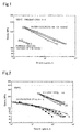
- FIG. 1 is a graph representing the influence of cooling rate on creep rupture time at 650°C in the steels 2 to 4 of the present invention. It can be seen that the water-cooled materials with a high cooling rate have creep rupture times about 10 times longer than those of the furnace cooled materials involving a low cooling rate.
- Table 3 represents the measured data used to create FIG. 1 .
- the present steel 3 The present steel 4
- the required cooling rate conditions include an annealing treatment within a temperature range of 1,000 to 1,250°C, and the subsequent cooling to 400°C--a temperature that essentially does not allow for precipitation of carbides, nitrides, and intermetallic compounds--at a high cooling rate that can suppress the precipitation of these components, specifically at 100°C/min or higher.
- FIG. 2 is a graph representing the results of a creep test at 650°C.
- the steels 1 to 4 of the present invention have higher creep strengths than comparative steels 9 to 15 in which Cr is added in less than 13% by mass, and in which the percentage volume of the ferrite phase is less than 70%.
- Table 4 represents the measured data used to create FIG. 2 .
- Table 4 Stress (MPa) Creep rupture time at 650°C (hr) The present steel Comparative steel 1 2 3 4 9 10 11 12 13 14 15 240 - 2405 2222 2008 - - - - - - 200 3834 5789 4620 3911 - - - - - - - 180 - - - - - 6 - - - - - 160 - - - - - 11 20 - - - - - 140 36418 25776 20074 13211 66 171 122 127 157 289 241 130 - - - - 194 564 - - - - - 120 - 49380 43299 25076 - - 804 670 985 1004 1008 110 - - - - 1689 2589 1670 1478 2171 1934 1615 100 - - - - 3739 4831 -
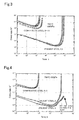
- FIG. 3 is a graph representing the relationship between creep rate and time at 700°C under stress of 100 MPa.
- the creep rates of the steels 2 and 4 of the present invention are only about 1/1,000 of the creep rates of comparative steels 9 to 11, and that the creep rupture times are at least about 100 times longer.
- Table 5 represents the minimum creep rates obtained from FIG. 3 .
- the steels 2 and 4 of the present invention have a minimum creep rate of 1.0 ⁇ 10 -4 /h or less, or 1.0 ⁇ 10 -5 /h or less.
- Table 5 700°C, Stress 100 MPa Tested material Minimum creep rate (h -1 )
- the present steel 2 2.0 x 10 -6
- the present steel 4 1.9 x 10 -6 Comparative steel 9 2.1 x 10 -3 Comparative steel 10 1.1 x 10 -3 Comparative steel 11 2.5 x 10 -3
- FIG. 4 is a graph representing the relationship between creep rate and time at 750°C under stress of 50 MPa.
- the steel 4 of the present invention did not rupture during the course of testing.
- the creep rates of the steels 2 and 4 of the present invention were only 1/100 or less of the creep rates of comparative steels 9 and 13, and the creep rupture times were at least about 100 times longer.
- Table 6 represents the measured data used to create FIG. 4 .
- Table 6 750°C, Stress 50 MPa Tested material Minimum creep rate (h -1 )
- the present steel 2 1.1 x 10 -6
- the present steel 4 7.4 x 10 -7 Comparative steel 9 5.3 x 10 -4 Comparative steel 13 5.2 x 10 -4
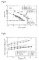
- FIG. 5 is a graph representing creep rupture time at 750°C.
- the steels 2 and 4 of the present invention did not rupture during the course of testing under stresses of 50 MPa and 30 MPa. Further, the steels 2 and 4 of the present invention tested under stresses of 80 to 50 MPa had creep rupture times at least about 100 times longer than the rupture times of comparative steels 9 to 15. It can also be seen that the creep rupture times are longer than those of the austenite heat-resistant steels 21 to 28 (SUS316) presented in Table 7. Further, it can be seen that, even under stress of 30 MPa, the steels 2 and 4 of the present invention have creep rupture times comparable to that of SUS316.
- Table 7 represents the measured data used to create FIG. 5 .
- Table 7 Creep rupture time at 750°C (hr) Stress
- the present steel Comparative steel Austenite steel (SUS316) (MPa) 2 4 9 10 11 12 13 14 15 21 22 23 24 25 26 27 28 88 127 135 145 162 163 170 173 194 80 2173 3550 69 555 577 615 641 656 680 802 61 1371 60 24 53 1725 2095 2137 2651 2691 2726 2735 2979 50 9033 >16154 97 97 108 92 47 5547 41 5384 6564 8302 8873 9266 11767 40 430 362 326 516 392 239 204 37 9613 23693 35 579 970 384 33 11188 18173 23024 33224 30 >21023 >20973 1994 1488 1043 1730 1018 667 26 33279 37610 44459 46417 53844 130478 25 3621 3079 2333 3882
- FIG. 6 is a graph representing the temperature dependence of linear expansion coefficient. The graph represents the results of the comparison of the linear expansion coefficients of the steels of the present invention and practical heat-resistant materials.
- the steels 2 and 4 of the present invention were heated from room temperature to 1,000°C at a rate of 1,000°C/h, and the thermal expansion was measured to determine a linear expansion coefficient at each temperature.
- the linear expansion coefficients of the practical heat-resistant materials are values specified in the boiler and pressure vessel specifications of the American Society of Mechanical Engineers (ASME).
- Table 8 represents the measured data used to create FIG. 6 .
- Table 8 Temperature °C Linear expansion coefficient ( ⁇ 10 -6 )
- the present steel Comparative steel 2 4 Ferrite steel Austenite steel Ni-based superalloy 9Cr-1 Mo 12Cr, 13Cr 18Cr-8Ni 25Cr-20Ni NCF600 NCF800 50 8.8 10.9 10.8 11.1 15.9 15.2 12.8 14.9 150 9.3 11.1 11.7 11.9 17.7 16.6 13.9 16.4 250 9.9 11.4 12.4 12.2 18.8 17.2 14.9 17.0 350 10.4 11.6 13.0 12.5 19.3 17.9 15.5 17.5 450 11.0 11.8 13.5 12.9 19.8 18.5 18.0 550 11.6 12.0 14.1 13.2 20.7 19.2 18.6 650 12.1 12.2 15.1 13.3 21.6 20.0 19.4 750 12.7 12.4 13.4 21.1 20.9 20.7 850 13.2 12.6 23.7
- the steels 2 and 4 of the present invention have a linear expansion coefficient of 15 ⁇ 10 -6 or less in a temperature range of from room temperature to 850°C, and that the low thermal expansion properties are comparable to, or better than those of the ferritic steel.
- the present invention realizes a ferritic Cr-steel that has improved heat resistance (creep strength) while maintaining low thermal expansion properties.
- the ferritic Cr-steel can realize a heat-resistant precision component for mechanical structures, such as turbines, used under high temperatures above 650°C.
Landscapes
- Chemical & Material Sciences (AREA)
- Engineering & Computer Science (AREA)
- Materials Engineering (AREA)
- Mechanical Engineering (AREA)
- Metallurgy (AREA)
- Organic Chemistry (AREA)
- Physics & Mathematics (AREA)
- Thermal Sciences (AREA)
- Crystallography & Structural Chemistry (AREA)
- Heat Treatment Of Articles (AREA)
- Turbine Rotor Nozzle Sealing (AREA)
Abstract
Description
- The present invention relates to ferritic Cr-steel used as material of precision components that have heat resistance.
- Ferritic Cr-steel (also called ferritic high Cr-steel) is generally used as material of precision components that have heat resistance (hereinafter, referred to as "heat-resistant precision components), for example, such as the rotors, discs, and blades of machines such as steam turbines and gas turbines used under high temperature, because large thermal expansion coefficient differences cause positional misalignment relative to the other components.
- However, in face of the recent demand for use of turbines under high temperatures above 650°C, a Ni-based superalloy has been proposed as material of heat-resistant precision components, as described in
Patent Document 1. - This is because the ferritic Cr-steel, which undergoes small dimensional changes by thermal expansion, has low high-temperature strength, and undergoes creep deformation and changes the shape of the precision component.
- However, the physical properties of the Ni-based superalloy do not allow the thermal expansion coefficient to be kept at values below that of the ferritic Cr-steel. In fact, further improvement in heat resistance tends to increase the thermal expansion coefficient.
- Indeed, there is a dilemma that the ferritic Cr-steel, with its small thermal expansion coefficient, has large creep deformation, and that the Ni-based superalloy, with its small creep deformation and high high-temperature strength, has a large thermal expansion coefficient.
- Accordingly, it is considered very difficult to realize a heat-resistant precision component that can withstand use under high temperatures above 650°C while undergoing only small changes in shape and dimension.
[Patent Document 1]JP-A-2007-332412 - The present invention has been made under these circumstances, and it is an object of the present invention to provide a ferritic Cr-steel for a heat-resistant precision component and a producing process thereof, and a heat-resistant precision component and a producing process thereof, with which heat resistance can be improved while providing low thermal expansion properties.
- In order to solve the foregoing problems, the present invention provides a ferritic Cr-steel for a heat-resistant precision component,
characterized in that the ferritic Cr-steel is of a chemical composition that mainly includes, in % by mass,
Cr: 13 to 30%,
Ni: 1 × 10⁻¹ to 2.5%,
C: 1 × 10⁻³ to 1 × 10⁻¹%, and
N: 1 × 10⁻³ to 1 × 10⁻¹%,
wherein the ferritic Cr-steel allows for inclusion of an additional component and unavoidable impurities, includes Fe as the remaining part, and forms a ferrite phase. - It is preferable in the ferritic Cr-steel for a heat-resistant precision component that Ni be added in an amount that satisfies the relationship Ni > 10(C + N), where Ni, C, and N each represent the amount of each component added (in % by mass), when C is added in 1 × 10⁻²% by mass or more and/or Ni is added in 1 × 10⁻²% by mass or more.
- It is preferable in the ferritic Cr-steel for a heat-resistant precision component that the ferrite phase be 70 volume% or more.
- It is preferable that the additional component be one or more of the following in % by mass,
Mo: 5 × 10⁻¹ to 5%,
W: 5 × 10⁻¹ to 1 × 10%,
V: 5 × 10⁻² to 4 × 10⁻¹%,
Nb: 1 × 10⁻² to 1 × 10⁻¹ %,
Co: 1 × 10⁻¹ to 1 × 10%, and
B: 2 × 10⁻³ to 4 × 10⁻³%, and
that at least one of carbide, nitride, and intermetallic compound be precipitated in crystal grains. - It is preferable in the ferritic Cr-steel for a heat-resistant precision component that Mo and W be added in amounts that satisfy the relationship Mo + 0.5W ≥ 3.0% by mass, where Mo and W each represent the amount of each component added (in % by mass).
- The present invention also provides a ferritic Cr-steel for use in a heat-resistant precision component and that contains Cr in an amount of from 13% by mass to 30% by mass,
- characterized in that the ferritic Cr-steel has a thermal expansion coefficient of 15 × 10-6 or less in a temperature range of from room temperature to 800°C, and a minimum creep rate of 1 × 10⁻⁴/h or less at 700°C under stress of 100 MPa.
- The present invention also provides a process for producing a ferritic Cr-steel for a heat-resistant precision component,
the process including hot working the ferritic Cr-steel of the foregoing chemical composition in a temperature range of 850 to 1,200°C, forming the ferritic Cr-steel into a predetermined shape, subjecting the steel to an annealing treatment in a temperature range of 1,000 to 1,250°C, and cooling the steel to 400°C or lower at a cooling rate of 100°C/min or higher. - The present invention also provides a heat-resistant precision component formed from the ferritic Cr-steel for a heat-resistant precision component.
- The heat-resistant precision component may be any one of a rotor, a disc, and a blade of a turbine.
- The present invention also provides a process for producing a heat-resistant precision component, the process including hot working the ferritic Cr-steel of the foregoing chemical composition in a temperature range of 850 to 1,200°C, forming the ferritic Cr-steel into a component shape, subjecting the steel to an annealing treatment in a temperature range of 1,000 to 1,250°C, and cooling the steel to 400°C or less at a cooling rate of 100°C/min or higher.
- The ferritic Cr-steel for a heat-resistant precision component and the producing process thereof, and the heat-resistant precision component and the producing process thereof of the present invention realize a heat-resistant precision component for mechanical structures, as represented by turbines, used under high temperature. The heat-resistant precision component has high heat resistance (creep strength) while maintaining optimum low thermal expansion properties.
-
-
FIG. 1 is a graph representing the influence of cooling rate on creep rupture time at 650°C. -
FIG. 2 is a graph representing the results of a creep test performed at 650°C. -
FIG. 3 is a graph representing the relationship between creep rate and time at 700°C under stress of 100 MPa. -
FIG. 4 is a graph representing the relationship between creep rate and time at 750°C under stress of 50 MPa. -
FIG. 5 is a graph representing creep rupture time at 750°C. -
FIG. 6 is a graph representing the temperature dependence of linear expansion coefficient. - The ferritic Cr-steel for a heat-resistant precision component of the present invention is a material used for components of mechanical structures such as turbines, and that has excellent high temperature strength, heat resistance, oxidation resistance, and high toughness even at high temperatures above 650°C (here and below, the temperature is represented in units of 50°C), and that can withstand use under high temperature and high pressure for extended time periods while undergoing only a limited decrease in strength.
- The ferritic Cr-steel for a heat-resistant precision component is produced by hot working a ferritic Cr-steel ingot in a temperature range of 850 to 1,200°C and forming the ferritic Cr-steel into a predetermined shape, and then subjecting the steel to an annealing treatment in a temperature range of 1,000 to 1,250°C, and cooling the steel to 400°C or less at a cooling rate of 100°C/min or higher.
- The hot working temperature such as in hot forging is 850 to 1,200°C, preferably 950 to 1,150°C, more preferably 1,000 to 1,100°C. Above the upper limit temperature, an abrupt decrease in ductility may occur. Below the lower limit temperature, deformation resistance increases, which may lead to processing defects such as cracking.
- The temperature of the annealing treatment is 1,000 to 1,250°C, preferably 1,000 to 1,200°C, more preferably 1,050 to 1,200°C. Above the upper limit temperature, serious coarsening of crystal grains may occur, which can be detrimental to various properties of the steel, including toughness, ductility, and weldability. Below the lower limit temperature, it may not be possible to completely melt the steel and to exhibit a sufficient strength.
- Temperatures of 400°C and higher may cause precipitation of a second phase in the process of cooling from the annealing temperature, because of the fast precipitation rate of second-phase compounds such as carbides, nitrides, and intermetallic compounds. In order to control such precipitation of the second phase, the cooling rate of the cooling to 400°C or less following the annealing treatment is 100°C/min or higher, preferably 120°C/min or higher, more preferably 150°C/min or higher. Below the lower limit, a coarse second phase may precipitate at the crystal grain boundary during the cooling process, and it becomes difficult to disperse and precipitate a fine second phase in the crystal grains. In this case, sufficient strength may not be developed because of the failure to effectively control the precipitation state of the second phase for strength improvement.
- The ferritic Cr-steel for a heat-resistant precision component produced as above has a linear expansion coefficient of 15 × 10-6 or less in a temperature range of from room temperature to 850°C. Above the upper limit, the amounts of thermal expansion and contraction at the start-up and stopping of a turbine increase, and it becomes difficult to produce heat-resistant precision components with high dimension accuracy.
- Further, the ferritic Cr-steel for a heat-resistant precision component has a minimum creep rate of 1.0 × 10⁻⁴/h or less, preferably 1.0 × 10⁻⁵/h or less at 700°C under stress of 100 MPa. A minimum creep rate exceeding the upper limit increases creep deformation that depends on the load generated during the operation of a turbine, and causes the rotation component rotor blade (blade) to contact the stationary components stator vane (vane) and vessel (casing) of the turbine, with the result that damage or other defects may occur.
- Further, the ferritic Cr-steel for a heat-resistant precision component has a creep rupture time of preferably 1,000 hr or more at 750°C under stress of 80 MPa, 5,000 hr or more at 750°C under stress of 50 MPa, and 10,000 hr or more at 750°C under stress of 30 MPa. A creep rupture time below the lower limit shortens the creep rupture lifetime that depends on the load generated during the operation of a turbine, and may thus present difficulties in ensuring a sufficient creep rupture lifetime in practical applications.
- The ferritic Cr-steel before forming into a shape, in the form of, for example, a steel ingot to be subjected to hot working is a ferritic Cr-steel, or a ferritic high Cr-steel as it is called, whose chemical composition is adjusted to include the components below (here and below, % means % by mass).
- C needs to be added in at least 1 × 10⁻³% to improve creep strength. The upper limit of the C additive amount is 1 × 10⁻¹%, because the excess addition lowers toughness. When C is added in 1 × 10⁻²% or more, it is preferable that Ni > 10 (C + N), where Ni, C, and N each represent the additive amount of each component (in % by mass).
- It is essential that Cr be added in 13% or more. In actual practice, Cr is added in preferably 13.5% or more to ensure a 70 volume% or more of the ferrite phase, and to improve oxidation resistance. The upper limit of Cr additive amount is 30%, because a Cr additive amount in excess of 30% notably lowers toughness.
- N needs to be added in at least 1 × 10⁻³% to improve creep strength. The upper limit of N additive amount is 1 × 10⁻¹%, because the excess addition lowers toughness. When N is added in 1 × 10⁻²% or more, it is preferable that Ni > 10 (C + N), as with the case of C.
- Ni needs to be added in at least 1 × 10⁻¹% to improve toughness. When C and/or N are added in 1 × 10⁻²% or more, it is preferable that the Ni additive amount satisfy Ni > 10 (C + N) to ensure toughness, as above. The upper limit of Ni additive amount is 2.5%, because the excess addition lowers the percentage volume of the ferrite phase.
- As presented in Table 2 below, comparative steels 7 and 8 with the Ni additive amount satisfying Ni ≤ 10 (C + N) (Ni, C, and N each represent the additive amount of each component (in % by mass)) have small Charpy impact values, regardless of the cooling rate. On the other hand, the water-cooled materials of the
steels 1 to 4 of the present invention satisfying the relationship Ni > 10 (C + N) have sufficiently greater Charpy impact values than those of the comparative steels 7 and 8. - The ferritic Cr-steel can be strengthened with the controlled precipitation of at least one of carbide, nitride, and intermetallic compound, specifically, by the fine dispersion and precipitation within the crystal grains. This is effective for improving creep strength. To this end, the ferritic Cr-steel allows for addition of the components below in its chemical composition, in addition to the foregoing components.
- Mo is a chemical component effective for precipitating an intermetallic compound, and can improve creep strength. Mo may be added in 5 × 10⁻¹% or more. The upper limit of Mo additive amount is preferably 5%, because the excess addition may lower toughness.
- As with Mo, W is a chemical component effective for precipitating an intermetallic compound, and can improve creep strength. W may be added in 5 × 10⁻¹% or more. The upper limit of W additive amount is preferably 1 × 10%, because the excess addition may lower toughness.
- Note that Mo and W may be added to satisfy the relationship Mo + 0.5W ≥ 3.0% (Mo and W each represent the additive amount (in % by mass)), so as to ensure a sufficient amount of intermetallic compound precipitation.
- V forms carbides or nitrides effective for improving creep strength. V maybe added in 5 × 10⁻²% or more. The upper limit of V additive amount is preferably 4 × 10⁻¹%, because the excess addition is not necessarily effective for the formation of carbides and nitrides.
- As with V, Nb forms carbides or nitrides effective for improving creep strength. Nb may be added in 1 × 10⁻²% or more. The upper limit of Nb additive amount is preferably 1 × 10⁻¹%, because the excess addition is not necessarily effective for the formation of carbides and nitrides.
- Co is a component effective for miniaturizing the precipitated carbide, nitride, and intermetallic compound, and for improving creep strength. Co may be added in 1 x 10⁻¹% or more. The upper limit of Co additive amount is preferably 1 × 10%, because the excess addition may lower the percentage volume of the ferrite phase.
- B is a component effective for miniaturizing and stabilizing the precipitates, and for strengthening the grain boundary. B may be added in 2 × 10⁻³% or more. The upper limit of B additive amount is preferably 4 × 10⁻³%, because the excess addition may lead to formation of boron nitride, and may not be necessarily effective for improving creep strength.
- Mn is a component effective as a deoxidant. Mn may be added in 5 × 10⁻²% or more. The upper limit of Mn additive amount is preferably 8 × 10⁻¹%, because the excess addition is detrimental to strength and toughness.
- Si is a component effective as a deoxidant. Si may be added in 5 × 10⁻²% or more. The upper limit of Si additive amount is preferably 5 × 10⁻¹%, because the excess addition accelerates the coarsening of the precipitates and lowers strength.
- The remaining parts of the chemical composition of the ferritic Cr-steel for a heat-resistant precision component are Fe and unavoidable impurities.
- Preferably, the ferritic Cr-steel for a heat-resistant precision component forms at least 70 volume% of the ferrite phase to improve creep strength. A tempered martensite structure is unstable at high temperatures, whereas the ferrite phase has high structure stability at high temperatures. As presented in Table 2, furnace cooling of the
steels 2 to 4 of the present invention makes the percentage volume of the ferrite phase less than 70% because of the slow cooling rate following the annealing treatment. However, the percentage volume of the ferrite phase becomes 70% or more when the cooling rate down to 400°C or less is 100°C/min or higher in water cooling. Thus, as represented inFIG. 1 , the water-cooled materials of thesteels 2 to 4 of the present invention have creep rupture times about 10 times longer than those of the furnace cooled materials. - Further, as presented in
FIG. 2 , thesteels 1 to 4 of the present invention have longer creep rupture times than thecomparative steels 9 to 15 in which the Cr additive amount is less than 13% and the percentage volume of the ferrite phase is less than 70%. - Examples are described below.
- In the following Examples, a round bar was assumed to be a component, and various properties were measured. It would be easily anticipated and understood that precision components, such as the rotor, disc, and blade of a turbine, produced from the ferritic Cr-steel has properties comparable to those of the ferritic Cr-steel used as the material.
- The round bars of
steels 1 to 8 with the chemical compositions presented in Table 1 (steels 1 to 6 of the present invention, and comparative steels 7 and 8) were each prepared from a 10-kg steel ingot subjected to 850 to 1,150°C hot forging to have a diameter of 15 mm. After 1,200°C annealing treatment, each specimen was cooled by furnace cooling or water cooling. - Note that Table 1 also presents the chemical compositions of the existing ferritic heat-resistant steels (steels 9 to 15; comparative steels).


- These test pieces were subjected to a Charpy impact test at 100°C. The results are presented in Table 2.
- Impact value was smaller in comparative steels 7 and 8 in which Ni was added in small amounts outside the range for the steels of the present invention, regardless of the cooling rate after the annealing treatment. In contrast, the
steels 1 to 4 of the present invention had greater impact values of 300 J/cm2 or more than the furnace cooled materials and comparative steels 7 and 8 in water cooling with a high cooling rate, though the values were small in furnace cooling that involves a lower cooling rate.Table 2 Specimen No. Impact value at 100°C (J/cm2) Percentage volume of ferrite phase (%) Remarks Furnace cooling Water cooling Furnace cooling Water cooling 1 6 300 94 100 2 6 333 56 83 3 5 367 48 77 4 6 366 40 72 7 12 32 100 100 Out of Ni range, Out of Co range 8 5 12 - 91 Out of Ni range -
FIG. 1 is a graph representing the influence of cooling rate on creep rupture time at 650°C in thesteels 2 to 4 of the present invention. It can be seen that the water-cooled materials with a high cooling rate have creep rupture times about 10 times longer than those of the furnace cooled materials involving a low cooling rate. - Table 3 represents the measured data used to create
FIG. 1 .Table 3 Stress (MPa) Creep rupture time at 650°C (hr) The present steel 2The present steel 3 The present steel 4Water cooling Furnace cooling Water cooling Furnace cooling Water cooling Furnace cooling 240 2405 - 2222 - 2008 - 200 5789 - 4620 - 3911 - 140 25776 1507 20074 1478 13211 1810 120 49380 2883 43299 3063 25076 3508 - It was confirmed that the required cooling rate conditions include an annealing treatment within a temperature range of 1,000 to 1,250°C, and the subsequent cooling to 400°C--a temperature that essentially does not allow for precipitation of carbides, nitrides, and intermetallic compounds--at a high cooling rate that can suppress the precipitation of these components, specifically at 100°C/min or higher.
-
FIG. 2 is a graph representing the results of a creep test at 650°C. - It can be seen that the
steels 1 to 4 of the present invention have higher creep strengths thancomparative steels 9 to 15 in which Cr is added in less than 13% by mass, and in which the percentage volume of the ferrite phase is less than 70%. - Table 4 represents the measured data used to create
FIG. 2 .Table 4 Stress (MPa) Creep rupture time at 650°C (hr) The present steel Comparative steel 1 2 3 4 9 10 11 12 13 14 15 240 - 2405 2222 2008 - - - - - - - 200 3834 5789 4620 3911 - - - - - - - 180 - - - - - 6 - - - - - 160 - - - - 11 20 - - - - - 140 36418 25776 20074 13211 66 171 122 127 157 289 241 130 - - - - 194 564 - - - - - 120 - 49380 43299 25076 - - 804 670 985 1004 1008 110 - - - - 1689 2589 1670 1478 2171 1934 1615 100 - - - - 3739 4831 - - - - - 90 - - - - 10002 11219 6473 4853 7249 5721 3412 80 - - - - 21717 21505 11283 6966 14462 10713 4783 70 - - - - 50871 46437 16377 12802 25632 18158 6909 60 - - - - - 65959 27733 25438 40713 34223 9734 -
FIG. 3 is a graph representing the relationship between creep rate and time at 700°C under stress of 100 MPa. - It can be seen that the creep rates of the
steels comparative steels 9 to 11, and that the creep rupture times are at least about 100 times longer. - Table 5 represents the minimum creep rates obtained from
FIG. 3 . Thesteels Table 5 700°C, Stress 100 MPaTested material Minimum creep rate (h-1) The present steel 22.0 x 10⁻⁶ The present steel 41.9 x 10⁻⁶ Comparative steel 92.1 x 10⁻³ Comparative steel 101.1 x 10⁻³ Comparative steel 112.5 x 10⁻³ -
FIG. 4 is a graph representing the relationship between creep rate and time at 750°C under stress of 50 MPa. - The
steel 4 of the present invention did not rupture during the course of testing. The creep rates of thesteels comparative steels 9 and 13, and the creep rupture times were at least about 100 times longer. - Table 6 represents the measured data used to create
FIG. 4 .Table 6 750°C, Stress 50 MPaTested material Minimum creep rate (h-1) The present steel 21.1 x 10⁻⁶ The present steel 47.4 x 10⁻⁷ Comparative steel 95.3 x 10⁻⁴ Comparative steel 13 5.2 x 10⁻⁴ -
FIG. 5 is a graph representing creep rupture time at 750°C. - The
steels steels comparative steels 9 to 15. It can also be seen that the creep rupture times are longer than those of the austenite heat-resistant steels 21 to 28 (SUS316) presented in Table 7. Further, it can be seen that, even under stress of 30 MPa, thesteels - Table 7 represents the measured data used to create
FIG. 5 .Table 7 Creep rupture time at 750°C (hr) Stress The present steel Comparative steel Austenite steel (SUS316) (MPa) 2 4 9 10 11 12 13 14 15 21 22 23 24 25 26 27 28 88 127 135 145 162 163 170 173 194 80 2173 3550 69 555 577 615 641 656 680 802 61 1371 60 24 53 1725 2095 2137 2651 2691 2726 2735 2979 50 9033 >16154 97 97 108 92 47 5547 41 5384 6564 8302 8873 9266 11767 40 430 362 326 516 392 239 204 37 9613 23693 35 579 970 384 33 11188 18173 23024 33224 30 >21023 >20973 1994 1488 1043 1730 1018 667 26 33279 37610 44459 46417 53844 130478 25 3621 3079 2333 3882 1307 20 5713 5050 7884 7115 4209 2819 -
FIG. 6 is a graph representing the temperature dependence of linear expansion coefficient. The graph represents the results of the comparison of the linear expansion coefficients of the steels of the present invention and practical heat-resistant materials. - The
steels - Table 8 represents the measured data used to create
FIG. 6 .Table 8 Temperature °C Linear expansion coefficient (×10-6) The present steel Comparative steel 2 4 Ferrite steel Austenite steel Ni-based superalloy 9Cr-1 Mo 12Cr, 13Cr 18Cr-8Ni 25Cr- 20Ni NCF600 NCF800 50 8.8 10.9 10.8 11.1 15.9 15.2 12.8 14.9 150 9.3 11.1 11.7 11.9 17.7 16.6 13.9 16.4 250 9.9 11.4 12.4 12.2 18.8 17.2 14.9 17.0 350 10.4 11.6 13.0 12.5 19.3 17.9 15.5 17.5 450 11.0 11.8 13.5 12.9 19.8 18.5 18.0 550 11.6 12.0 14.1 13.2 20.7 19.2 18.6 650 12.1 12.2 15.1 13.3 21.6 20.0 19.4 750 12.7 12.4 13.4 21.1 20.9 20.7 850 13.2 12.6 23.7 - It can be seen that the
steels - The present invention realizes a ferritic Cr-steel that has improved heat resistance (creep strength) while maintaining low thermal expansion properties. The ferritic Cr-steel can realize a heat-resistant precision component for mechanical structures, such as turbines, used under high temperatures above 650°C.
Claims (10)
- A ferritic Cr-steel for a heat-resistant precision component,
characterized in that the ferritic Cr-steel is of a chemical composition that mainly includes, in % by mass,
Cr: 13 to 30%,
Ni: 1 × 10⁻¹ to 2.5%,
C: 1 × 10⁻³ to 1 × 10⁻¹%, and
N: 1 × 10⁻³ to 1 × 10⁻¹%,
wherein the ferritic Cr-steel allows for inclusion of an additional component and unavoidable impurities, includes Fe as the remaining part, and forms a ferrite phase. - The ferritic Cr-steel for a heat-resistant precision component according to claim 1, wherein Ni is added in an amount that satisfies the relationship Ni > 10(C + N), where Ni, C, and N each represent the amount of each component added (in % by mass), when C is added in 1 × 10⁻²% by mass or more and/or Ni is added in 1 × 10⁻²% by mass or more.
- The ferritic Cr-steel for a heat-resistant precision component according to claim 1 or 2, wherein the ferrite phase is 70 volume% or more.
- The ferritic Cr-steel for a heat-resistant precision component according to claim 1 or 2, wherein the additional component is one or more of the following in % by mass,
Mo: 5 × 10⁻¹ to 5%,
W:5 × 10⁻¹ to 1 × 10%,
V: 5 × 10⁻² to 4 × 10⁻¹%,
Nb: 1 × 10⁻² to 1 × 10⁻¹%,
Co: 1 × 10⁻¹ to 1 × 10%, and
B: 2 × 10⁻³ to 4 × 10⁻³%, and
wherein at least one of carbide, nitride, and intermetallic compound is precipitated in crystal grains. - The ferritic Cr-steel for a heat-resistant precision component according to claim 4, wherein Mo and W are added in amounts that satisfy the relationship Mo + 0.5W ≥ 3.0% by mass, where Mo and W each represent the amount of each component added (in % by mass).
- A ferritic Cr-steel for use in a heat-resistant precision component and that contains Cr in an amount of from 13% by mass to 30% by mass,
characterized in that the ferritic Cr-steel has a thermal expansion coefficient of 15 × 10-6 or less in a temperature range of from room temperature to 800°C, and a minimum creep rate of 1 × 10⁻⁴/h or less at 700°C under stress of 100 MPa. - A process for producing a ferritic Cr-steel for a heat-resistant precision component,
the process comprising hot working the ferritic Cr-steel of the chemical composition of claim 1 in a temperature range of 850 to 1,200°C, forming the ferritic Cr-steel into a predetermined shape, subjecting the steel to an annealing treatment in a temperature range of 1,000 to 1,250°C, and cooling the steel to 400°C or less at a cooling rate of 100°C/min or higher. - A heat-resistant precision component formed from the ferritic Cr-steel for a heat-resistant precision component of claim 1.
- The heat-resistant precision component according to claim 8, wherein the heat-resistant precision component is any one of a rotor, a disc, and a blade of a turbine.
- A process for producing a heat-resistant precision component,
the process comprising hot working the ferritic Cr-steel of the chemical composition of claim 1 in a temperature range of 850 to 1,200°C, forming the ferritic Cr-steel into a component shape, subjecting the steel to an annealing treatment in a temperature range of 1,000 to 1,250°C, and cooling the steel to 400°C or less at a cooling rate of 100°C/min or higher.
Applications Claiming Priority (2)
| Application Number | Priority Date | Filing Date | Title |
|---|---|---|---|
| JP2009143774A JP5713250B2 (en) | 2009-06-17 | 2009-06-17 | Heat-resistant precision parts |
| PCT/JP2010/059453 WO2010146999A1 (en) | 2009-06-17 | 2010-06-03 | FERRITIC Cr-STEEL FOR HEAT-RESISTANT PRECISION COMPONENT AND METHOD FOR PRODUCING SAME, AND HEAT-RESISTANT PRECISION COMPONENT AND METHOD FOR PRODUCING SAME |
Publications (2)
| Publication Number | Publication Date |
|---|---|
| EP2444508A1 true EP2444508A1 (en) | 2012-04-25 |
| EP2444508A4 EP2444508A4 (en) | 2014-06-18 |
Family
ID=43356320
Family Applications (1)
| Application Number | Title | Priority Date | Filing Date |
|---|---|---|---|
| EP10789374.5A Withdrawn EP2444508A4 (en) | 2009-06-17 | 2010-06-03 | FERRITIC CHROMIUM STEEL FOR HEAT RESISTANT PRECISION COMPONENT AND METHOD FOR PRODUCING THE SAME AND HEAT RESISTANT PRECISION COMPONENT AND METHOD FOR PRODUCING THE SAME |
Country Status (4)
| Country | Link |
|---|---|
| US (1) | US20120132325A1 (en) |
| EP (1) | EP2444508A4 (en) |
| JP (1) | JP5713250B2 (en) |
| WO (1) | WO2010146999A1 (en) |
Families Citing this family (1)
| Publication number | Priority date | Publication date | Assignee | Title |
|---|---|---|---|---|
| JP5713250B2 (en) * | 2009-06-17 | 2015-05-07 | 独立行政法人物質・材料研究機構 | Heat-resistant precision parts |
Family Cites Families (9)
| Publication number | Priority date | Publication date | Assignee | Title |
|---|---|---|---|---|
| JP3269799B2 (en) * | 1998-02-20 | 2002-04-02 | 川崎製鉄株式会社 | Ferritic stainless steel for engine exhaust parts with excellent workability, intergranular corrosion resistance and high-temperature strength |
| US6696016B1 (en) * | 1999-09-24 | 2004-02-24 | Japan As Represented By Director General Of National Research Institute For Metals | High-chromium containing ferrite based heat resistant steel |
| JP3843314B2 (en) * | 1999-09-24 | 2006-11-08 | 独立行政法人物質・材料研究機構 | High Cr ferritic heat resistant steel |
| JP3777421B2 (en) * | 2002-02-28 | 2006-05-24 | 独立行政法人物質・材料研究機構 | High chromium ferritic heat resistant steel |
| JP4206836B2 (en) * | 2002-06-17 | 2009-01-14 | Jfeスチール株式会社 | Ferritic stainless steel with excellent corrosion resistance, high temperature strength and high temperature oxidation resistance |
| US8790573B2 (en) * | 2003-12-26 | 2014-07-29 | Jfe Steel Corporation | Ferritic Cr-contained steel |
| JP5396752B2 (en) * | 2007-10-02 | 2014-01-22 | Jfeスチール株式会社 | Ferritic stainless steel with excellent toughness and method for producing the same |
| JP4743190B2 (en) * | 2007-10-22 | 2011-08-10 | コベルコ建機株式会社 | Valve operating device for construction machinery |
| JP5713250B2 (en) * | 2009-06-17 | 2015-05-07 | 独立行政法人物質・材料研究機構 | Heat-resistant precision parts |
-
2009
- 2009-06-17 JP JP2009143774A patent/JP5713250B2/en not_active Expired - Fee Related
-
2010
- 2010-06-03 US US13/378,158 patent/US20120132325A1/en not_active Abandoned
- 2010-06-03 EP EP10789374.5A patent/EP2444508A4/en not_active Withdrawn
- 2010-06-03 WO PCT/JP2010/059453 patent/WO2010146999A1/en not_active Ceased
Also Published As
| Publication number | Publication date |
|---|---|
| WO2010146999A1 (en) | 2010-12-23 |
| US20120132325A1 (en) | 2012-05-31 |
| EP2444508A4 (en) | 2014-06-18 |
| JP2011001574A (en) | 2011-01-06 |
| JP5713250B2 (en) | 2015-05-07 |
Similar Documents
| Publication | Publication Date | Title |
|---|---|---|
| JP5562825B2 (en) | Heat-resistant cast steel, method for producing heat-resistant cast steel, cast component for steam turbine, and method for producing cast component for steam turbine | |
| EP2885440B1 (en) | High-chromium heat-resistant steel | |
| CN103602919B (en) | Forging heat resisting steel and manufacture method, forged part and manufacture method thereof | |
| JP4262414B2 (en) | High Cr ferritic heat resistant steel | |
| US6030469A (en) | Fully martensitic steel alloy | |
| JP6562476B2 (en) | Ferritic heat resistant steel and its manufacturing method | |
| CN102517517A (en) | Refractory steel for vane of steam turbine of ultra supercritical fossil power plant and manufacturing method | |
| US6793744B1 (en) | Martenstic stainless steel having high mechanical strength and corrosion | |
| CN104451086B (en) | The manufacture method of steamturbine rotor | |
| CN102517508A (en) | Ferrite refractory steel for vane of steam turbine of ultra supercritical fossil power plant and manufacturing method | |
| JPH1088291A (en) | Heat resistant cast steel with high strength and high toughness | |
| JP5265325B2 (en) | Heat resistant steel with excellent creep strength and method for producing the same | |
| JP3768091B2 (en) | High strength and high corrosion resistance martensitic stainless steel and manufacturing method thereof | |
| CN102383050A (en) | Cr-Ni based high temperature-resistant oxyaustenitic heat-resistant steel bar and preparation method thereof | |
| JPH1192881A (en) | Ferritic heat-resistant steel with lath martensite structure and its manufacturing method | |
| EP2444508A1 (en) | FERRITIC Cr-STEEL FOR HEAT-RESISTANT PRECISION COMPONENT AND METHOD FOR PRODUCING SAME, AND HEAT-RESISTANT PRECISION COMPONENT AND METHOD FOR PRODUCING SAME | |
| JP5981357B2 (en) | Heat resistant steel and steam turbine components | |
| KR20250112825A (en) | Austenitic stainless steel | |
| JP2016065265A (en) | Heat resistant steel for steam turbine rotor blade and steam turbine rotor blade | |
| JP2000273582A (en) | Cast steel for pressure vessel and production of pressure vessel using the same | |
| JP2001152293A (en) | High Cr ferritic heat resistant steel | |
| EP2447384A1 (en) | Heat-resistant component for chemical processing apparatus and method for producing same | |
| JP3250263B2 (en) | Manufacturing method of martensitic stainless steel seamless steel pipe excellent in toughness and stress corrosion cracking resistance | |
| JP5996403B2 (en) | Heat resistant steel and method for producing the same | |
| JP6173956B2 (en) | Austenitic heat resistant steel and turbine parts |
Legal Events
| Date | Code | Title | Description |
|---|---|---|---|
| PUAI | Public reference made under article 153(3) epc to a published international application that has entered the european phase |
Free format text: ORIGINAL CODE: 0009012 |
|
| 17P | Request for examination filed |
Effective date: 20120105 |
|
| AK | Designated contracting states |
Kind code of ref document: A1 Designated state(s): AL AT BE BG CH CY CZ DE DK EE ES FI FR GB GR HR HU IE IS IT LI LT LU LV MC MK MT NL NO PL PT RO SE SI SK SM TR |
|
| DAX | Request for extension of the european patent (deleted) | ||
| A4 | Supplementary search report drawn up and despatched |
Effective date: 20140520 |
|
| RIC1 | Information provided on ipc code assigned before grant |
Ipc: F01D 5/28 20060101ALI20140514BHEP Ipc: C21D 9/00 20060101ALI20140514BHEP Ipc: F02C 7/00 20060101ALI20140514BHEP Ipc: C22C 38/54 20060101ALI20140514BHEP Ipc: F01D 25/00 20060101ALI20140514BHEP Ipc: C22C 38/00 20060101AFI20140514BHEP Ipc: C21D 6/00 20060101ALI20140514BHEP |
|
| STAA | Information on the status of an ep patent application or granted ep patent |
Free format text: STATUS: THE APPLICATION IS DEEMED TO BE WITHDRAWN |
|
| 18D | Application deemed to be withdrawn |
Effective date: 20141217 |