EP2444239B1 - Iso-Rasterverbundkomponente - Google Patents
Iso-Rasterverbundkomponente Download PDFInfo
- Publication number
- EP2444239B1 EP2444239B1 EP11182608.7A EP11182608A EP2444239B1 EP 2444239 B1 EP2444239 B1 EP 2444239B1 EP 11182608 A EP11182608 A EP 11182608A EP 2444239 B1 EP2444239 B1 EP 2444239B1
- Authority
- EP
- European Patent Office
- Prior art keywords
- uni
- tape
- ply
- spacer
- iso
- Prior art date
- Legal status (The legal status is an assumption and is not a legal conclusion. Google has not performed a legal analysis and makes no representation as to the accuracy of the status listed.)
- Active
Links
Images



Classifications
-
- B—PERFORMING OPERATIONS; TRANSPORTING
- B29—WORKING OF PLASTICS; WORKING OF SUBSTANCES IN A PLASTIC STATE IN GENERAL
- B29C—SHAPING OR JOINING OF PLASTICS; SHAPING OF MATERIAL IN A PLASTIC STATE, NOT OTHERWISE PROVIDED FOR; AFTER-TREATMENT OF THE SHAPED PRODUCTS, e.g. REPAIRING
- B29C70/00—Shaping composites, i.e. plastics material comprising reinforcements, fillers or preformed parts, e.g. inserts
- B29C70/04—Shaping composites, i.e. plastics material comprising reinforcements, fillers or preformed parts, e.g. inserts comprising reinforcements only, e.g. self-reinforcing plastics
- B29C70/28—Shaping operations therefor
- B29C70/30—Shaping by lay-up, i.e. applying fibres, tape or broadsheet on a mould, former or core; Shaping by spray-up, i.e. spraying of fibres on a mould, former or core
-
- B—PERFORMING OPERATIONS; TRANSPORTING
- B23—MACHINE TOOLS; METAL-WORKING NOT OTHERWISE PROVIDED FOR
- B23P—METAL-WORKING NOT OTHERWISE PROVIDED FOR; COMBINED OPERATIONS; UNIVERSAL MACHINE TOOLS
- B23P15/00—Making specific metal objects by operations not covered by a single other subclass or a group in this subclass
- B23P15/04—Making specific metal objects by operations not covered by a single other subclass or a group in this subclass turbine or like blades from several pieces
-
- B—PERFORMING OPERATIONS; TRANSPORTING
- B29—WORKING OF PLASTICS; WORKING OF SUBSTANCES IN A PLASTIC STATE IN GENERAL
- B29C—SHAPING OR JOINING OF PLASTICS; SHAPING OF MATERIAL IN A PLASTIC STATE, NOT OTHERWISE PROVIDED FOR; AFTER-TREATMENT OF THE SHAPED PRODUCTS, e.g. REPAIRING
- B29C70/00—Shaping composites, i.e. plastics material comprising reinforcements, fillers or preformed parts, e.g. inserts
- B29C70/04—Shaping composites, i.e. plastics material comprising reinforcements, fillers or preformed parts, e.g. inserts comprising reinforcements only, e.g. self-reinforcing plastics
- B29C70/06—Fibrous reinforcements only
- B29C70/08—Fibrous reinforcements only comprising combinations of different forms of fibrous reinforcements incorporated in matrix material, forming one or more layers, and with or without non-reinforced layers
- B29C70/083—Combinations of continuous fibres or fibrous profiled structures oriented in one direction and reinforcements forming a two dimensional structure, e.g. mats
- B29C70/085—Combinations of continuous fibres or fibrous profiled structures oriented in one direction and reinforcements forming a two dimensional structure, e.g. mats the structure being deformed in a three dimensional configuration
-
- B—PERFORMING OPERATIONS; TRANSPORTING
- B29—WORKING OF PLASTICS; WORKING OF SUBSTANCES IN A PLASTIC STATE IN GENERAL
- B29D—PRODUCING PARTICULAR ARTICLES FROM PLASTICS OR FROM SUBSTANCES IN A PLASTIC STATE
- B29D28/00—Producing nets or the like, e.g. meshes, lattices
- B29D28/005—Reticulated structure comprising reinforcements of substantial or continuous length
-
- Y—GENERAL TAGGING OF NEW TECHNOLOGICAL DEVELOPMENTS; GENERAL TAGGING OF CROSS-SECTIONAL TECHNOLOGIES SPANNING OVER SEVERAL SECTIONS OF THE IPC; TECHNICAL SUBJECTS COVERED BY FORMER USPC CROSS-REFERENCE ART COLLECTIONS [XRACs] AND DIGESTS
- Y10—TECHNICAL SUBJECTS COVERED BY FORMER USPC
- Y10T—TECHNICAL SUBJECTS COVERED BY FORMER US CLASSIFICATION
- Y10T156/00—Adhesive bonding and miscellaneous chemical manufacture
- Y10T156/10—Methods of surface bonding and/or assembly therefor
-
- Y—GENERAL TAGGING OF NEW TECHNOLOGICAL DEVELOPMENTS; GENERAL TAGGING OF CROSS-SECTIONAL TECHNOLOGIES SPANNING OVER SEVERAL SECTIONS OF THE IPC; TECHNICAL SUBJECTS COVERED BY FORMER USPC CROSS-REFERENCE ART COLLECTIONS [XRACs] AND DIGESTS
- Y10—TECHNICAL SUBJECTS COVERED BY FORMER USPC
- Y10T—TECHNICAL SUBJECTS COVERED BY FORMER US CLASSIFICATION
- Y10T428/00—Stock material or miscellaneous articles
- Y10T428/24—Structurally defined web or sheet [e.g., overall dimension, etc.]
- Y10T428/24479—Structurally defined web or sheet [e.g., overall dimension, etc.] including variation in thickness
- Y10T428/24612—Composite web or sheet
Definitions
- the present disclosure relates to an iso-grid composite component and more particularly to gas turbine engines having convergent/divergent nozzles with iso-grid composite components.
- a variable area exhaust nozzle optimizes the thrust produced within a gas turbine engine.
- convergent/divergent (C/D) nozzles provide a multitude of nozzle positions.
- the term "convergent-divergent” describes an exhaust nozzle having a convergent section upstream of a divergent section. Exhaust gases exiting the turbine section pass through the decreasing diameter convergent section before passing through the increasing diameter divergent section.
- the convergent section is pivotally connected to an exhaust duct structure and to the divergent section.
- the divergent section is pivotally connected to the convergent section and to an external fairing positioned radially outboard of the divergent section.
- the upstream end of the external fairing is pivotally attached to an outer static structure to provide an outer aerodynamic surface for the C/D nozzle.
- the convergent, divergent, and external fairing sections generally include flaps and seals to accommodate changes in the nozzle variable orifice area and axis skew (if the nozzle is vectorable) by sliding relative to and overlapping each other as the orifice area decreases or increases.
- the flaps and seals are often manufactured of carbon fiber composites which incorporate either monocoque constructions (consistent thickness part) or hollow rib reinforcements. Although effective, these techniques may require significant weight or design space.
- EP 0953433 discloses an iso-grid composite component and a method of producing the same.
- an iso-grid composite component as set forth in claim 1.
- Figure 1 schematically illustrates a convergent/divergent (C/D) nozzle system 20 for a gas turbine engine.
- the nozzle system 20 is movable between a minimal dilated position ( Figure 1 ), which is typical during non-afterburning operation and a maximum dilated position (not shown), which is typical during afterburning operation.
- the nozzle system 20 generally includes a plurality of circumferentially distributed convergent flaps 22, each pivotably connected to a nozzle static structure 24.
- a plurality of circumferentially distributed divergent flaps 28 are pivotably connected through a joint structure 30 to adjust an aft end section of each convergent flap 22.
- a plurality of convergent seals 32 are each pivotally connected to a respective divergent seal 34 which are respectively distributed circumferentially between each divergent flap 28 and convergent flap 22 sets.
- Each convergent seal 32 is pivotably connected to the static structure 24 with each divergent seal 34 pivotably connected through a joint structure 36 adjacent an aft end section of each convergent seal 32.
- the convergent and divergent flaps 22, 28 and the convergent and divergent seals 32, 34 taken collectively, define the radial outer boundary of a combustion gas path F to define a convergent section 38 and a divergent section 40 with a throat area 42 defined therebetween ( Figure 2 ).
- an outer aerodynamic surface of the nozzle system 20 is defined by a plurality of external flaps 50 ( Figures 3 and 4 ).
- Each of the plurality of external flaps 50 pivot relative a respective divergent flap 28 about a pivot axis 52 defined by an external flap hinge 54 ( Figure 4 ).
- Each of the plurality of external flaps 50 also slide relative the nozzle static structure 24 through track arms 56 ( Figure 4 ).
- the plurality of external flaps 50 taken collectively, define an outer aerodynamic surface of the nozzle system 20 and accommodate movement between the maximum dilated position and the minimal dilated position through sliding movement relative the static structure 24 and overlapping movement between adjacent external flaps 50.
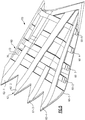
- each external flap 50 includes an iso-grid construction ( Figure 6 ) that alternatively interrupts the internal load paths within a multiple of lateral ribs 60 and longitudinal ribs 62 so as to prevent an internal thermal fight which would hereto for cause internal dissolution of the component.
- the external flap 50 includes four longitudinal ribs 62-1 - 62 -4 and five lateral ribs 60-1 - 60-5. It should be understood that the particular rib arrangement is related to the desired shape of the component such as the external flap 50.
- the iso-grid construction is illustrated herein with regards to an external flap 50 in accords with one non-limiting embodiment, it should be realized that any composite iso-grid structure will benefit herefrom. It should also be understood that although relatively rectilinear iso-grid geometry is illustrated, other geometries are usable herewith.
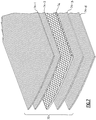
- each uni-tape ply bundle 70 is a buildup of four (4) uni-tape plies 74-1; 74-2;74-3; 74-4 and one spacer ply 76 such that the spacer ply 76 separates two (2) uni-tape plies 74-1; 74-2 from two (2) uni-tape plies 74-3; 74-4 ( Figure 7 ).
- Two (2) uni-tape plies 74 are generally of an equivalent height to one spacer ply 76 such that one (1) uni-tape ply bundle 70 is of an approximate equivalent height to three (3) spacer plies 76 within each of the ribs 60, 62. Generally, no more than 4 uni-tape plies are located adjacent to each other and the middle spacer ply 76 of the uni-tape ply bundle 70 may be oriented at a 45° direction to the associated uni-tape ply 74 direction.
- the iso-grid composite component construction makes use of the higher strength uni-tape plies 74 to build up strong and low weight internal ribs 60, 62.
- Internal thermal fights between transverse uni-tape plies 74 are avoided by selectively alternating each uni-tape ply bundle 70 at different heights within the rib pattern such that when one un-interrupted uni-tape ply bundle 70 is within one level of the longitudinal rib 62, the lateral rib 60 transverse thereto is defined by a spacer 72 which is interrupted at that level.
- the uni-tape ply bundle 70 runs un-interrupted within the lateral rib 60 while the longitudinal rib 62 at the same level includes the interrupted spacer 72.
- each uni-tape ply bundle 70 runs un-interrupted regardless of the level or direction for that particular uni-tape ply bundle 70. It should be understood that any number of levels may be provided to build up the particular iso-grid component such as the disclosed external flap 50.
- each level of uni-tape ply bundles 70 and spacers 72 which form the multiple of lateral ribs 60 and longitudinal ribs 62 may be separated by an interstitial ply layer 80.
- Each interstitial ply layer 80 may itself be a layup of any number of spacer plies such as fabric plies which are arranged at particular relative angular orientations. It should be understood that any number of such plies may be so utilized between the multiple of lateral ribs 60 and longitudinal ribs 62.
- the uni-tape ply bundles 70 are uninterrupted and the spacers 72 are utilized to equalize height such that the uni-tape ply bundles 70 within the lateral ribs 60 and longitudinal ribs 62 do not directly overlap to form uni-tape ply "bumps" at intersections between the lateral ribs 60 and longitudinal ribs 62 (the uni-tape ply bundles and the spacers may be of approximately equal height).
- transverse uni-tape ply bundles 70 are separated and spaced by the spacers 72 so that a constant height is maintained as Applicant has determined that such "bumps" may result in delamination regions since uni-tape has an inherent difference in thermal growth along the fiber direction as compared to across the fiber direction. Typical differences in this thermal growth approach 20 times such that the thermal expansion at a "bump" in conventional rib layups in which uni-tape directly overlaps and forms a "bump” may often result in delaminating and potential internally generated destruction of the layup. Moreover, Applicant has determined that the spacers 72 cushion and accommodate the thermal expansion which results in a robust but relatively light weight component.
- the iso-grid construction is lighter than monocoque constructions as uni-tape fibers can be placed to selectively follow the load paths.
- the iso-grid construction is also considerably more compact in the thickness direction than top hat hollow rib construction which facilitates usage in confined regions such as C/D nozzles as well as various other components.
Landscapes
- Engineering & Computer Science (AREA)
- Mechanical Engineering (AREA)
- Chemical & Material Sciences (AREA)
- Composite Materials (AREA)
- Moulding By Coating Moulds (AREA)
Claims (11)
- Iso-Rasterverbundkomponente (50), Folgendes umfassend:ein mehrlagiges Unibandbündel (70); undeinen Abstandshalter (72), der transversal zu dem mehrlagigen Unibandbündel (70) ist, wobei der Abstandshalter (72) durch das mehrlagige Unibandbündel (70) unterbrochen ist;wobei das mehrlagige Unibandbündel (70) mindestens teilweise eine erste Rippe (60) definiert und der Abstandshalter (72) mindestens teilweise eine zweite Rippe (62) definiert, die transversal zu der ersten Rippe (60) ist;wobei das mehrlagige Unibandbündel (70) eine Ansammlung von einem Vielfachen von Unibandlagen (74-1...74-4) und einer Abstandshalterlage (76) ist, sodass die Abstandshalterlage (76) ein Vielfaches von Unibandlagen (74-1...74-4) trennt.
- Iso-Rasterverbundkomponente nach Anspruch 1, wobei das mehrlagige Unibandbündel (70) eine Ansammlung von vier (4) Unibandlagen (74-1...74-4) und einer Abstandshalterlage (76) ist, sodass die Abstandshalterlage (76) zwei (2) Unibandlagen (74-1, 74-2) von zwei (2) Unibandlagen (74-3, 74-4) trennt.
- Iso-Rasterverbundkomponente nach Anspruch 2, wobei der Abstandshalter (72) eine Ansammlung von drei Abstandshalterlagen ist.
- Iso-Rasterverbundkomponente nach einem der vorhergehenden Ansprüche, wobei das mehrlagige Unibandbündel (70) und der Abstandshalter (72) ungefähr die gleiche Höhe aufweisen.
- Iso-Rasterverbundkomponente nach einem der vorhergehenden Ansprüche, ferner eine mehrlagige Zwischenschicht (80) umfassend, die an das mehrlagige Unibandbündel (70) und den Abstandshalter (72) angrenzt.
- Iso-Rasterverbundkomponente nach Anspruch 5, ferner einen zweiten Abstandshalter (72) und ein zweites mehrlagiges Unibandbündel (70) umfassend, das an die mehrlagige Zwischenschicht (80) angrenzt, wobei der zweite Abstandshalter (72) mindestens teilweise die erste Rippe (60) definiert und das zweite mehrlagige Unibandbündel (70) mindestens teilweise die zweite Rippe (62) definiert.
- Iso-Rasterverbundkomponente nach einem der Ansprüche 1 bis 3, ein Vielfaches von mehrlagigen Unibandbündeln (70) umfassend, von denen sich jedes Vielfache von mehrlagigen Unibandbündeln (70) auf verschiedenen Ebenen innerhalb eines Rippenmusters befindet, sodass kein mehrlagiges Unibandbündel (70) innerhalb einer Ebene einer ersten Rippe (60) des Rippenmusters durch einen Abstandshalter (72) unterbrochen ist, der mindestens teilweise eine zweite Rippe (62) des Rippenmusters definiert, die auf der entsprechenden Ebene transversal zu der ersten Rippe (60) ist.
- Iso-Rasterverbundkomponente nach Anspruch 7, wobei jedes Vielfache von mehrlagigen Unibandbündeln (70) und der Abstandshalter (72) innerhalb der entsprechenden Ebene von ungefähr gleicher Höhe sind.
- Iso-Rasterverbundkomponente nach Anspruch 7 oder 8, ferner eine mehrlagige Zwischenschicht (80) umfassend, die an jede Ebene des Vielfachen von mehrlagigen Unibandbündeln (70) und den Abstandshalter (72) innerhalb der entsprechenden Ebene angrenzt.
- Verfahren zum Definieren einer Rippenstruktur innerhalb einer Iso-Rasterverbundkomponente (50), Folgendes umfassend:Definieren einer ersten Rippe (60), mindestens teilweise mit einem mehrlagigen Unibandbündel (70), in einer ersten Ebene, wobei das mehrlagige Unibandbündel (70) eine Ansammlung von einem Vielfachen von Unibandlagen (74-1...74-4) und einer Abstandshalterlage (76) ist, sodass die Abstandshalterlage (76) ein Vielfaches von Unibandlagen (74-1...74-4) trennt; undDefinieren einer zweiten Rippe (62), die transversal zu der ersten Rippe (60) ist, mindestens teilweise mit einem Abstandshalter (72) in der ersten Ebene, wobei der Abstandshalter (72) durch das mehrlagige Unibandbündel (70) unterbrochen ist.
- Verfahren nach Anspruch 10, ferner Folgendes umfassend:
Beibehalten einer ungefähr gleichen Höhe des mehrlagigen Unibandbündels (70) und des Abstandshalters (72) innerhalb der ersten Ebene.
Applications Claiming Priority (1)
| Application Number | Priority Date | Filing Date | Title |
|---|---|---|---|
| US12/892,014 US9126374B2 (en) | 2010-09-28 | 2010-09-28 | Iso-grid composite component |
Publications (2)
| Publication Number | Publication Date |
|---|---|
| EP2444239A1 EP2444239A1 (de) | 2012-04-25 |
| EP2444239B1 true EP2444239B1 (de) | 2020-04-29 |
Family
ID=44862484
Family Applications (1)
| Application Number | Title | Priority Date | Filing Date |
|---|---|---|---|
| EP11182608.7A Active EP2444239B1 (de) | 2010-09-28 | 2011-09-23 | Iso-Rasterverbundkomponente |
Country Status (2)
| Country | Link |
|---|---|
| US (3) | US9126374B2 (de) |
| EP (1) | EP2444239B1 (de) |
Citations (1)
| Publication number | Priority date | Publication date | Assignee | Title |
|---|---|---|---|---|
| US5814386A (en) * | 1995-12-01 | 1998-09-29 | Mcdonnell Douglas Corporation | Composite shell formed as a body of rotation, and method and mandrel for making same |
Family Cites Families (146)
| Publication number | Priority date | Publication date | Assignee | Title |
|---|---|---|---|---|
| US2688327A (en) | 1950-08-11 | 1954-09-07 | Berg Samuel | Colostomy device |
| US2999780A (en) | 1953-11-13 | 1961-09-12 | H D Boggs Company Ltd | Method of casting tubular articles |
| US2898940A (en) | 1957-05-13 | 1959-08-11 | Jr Howard W Cole | High pressure hose |
| NL102542C (de) | 1958-02-25 | 1900-01-01 | ||
| US3088174A (en) | 1959-01-28 | 1963-05-07 | Gen Motors Corp | Method of producing a reinforced plastic die |
| US3093160A (en) | 1959-12-04 | 1963-06-11 | H D Boggs Company Ltd | Plastic articles |
| US3013315A (en) | 1960-06-03 | 1961-12-19 | Stauffer Chemical Co | Apparatus for centrifugal casting |
| US3075249A (en) | 1960-09-06 | 1963-01-29 | Emsig Mfg Co | Process for compression molding embossed articles |
| BE629966A (de) | 1962-03-22 | |||
| US3272686A (en) | 1962-03-23 | 1966-09-13 | Corning Glass Works | Structural ceramic bodies and method of making same |
| US3210233A (en) | 1962-08-27 | 1965-10-05 | Mcdonnell Aircraft Corp | Heat insulating and ablative structure and method of making same |
| US3134705A (en) | 1962-10-15 | 1964-05-26 | Dow Chemical Co | Honeycomb fabrication |
| US3341395A (en) | 1962-12-03 | 1967-09-12 | Solar Reflection Room Corp | Lightweight structural panel |
| US3349157A (en) | 1965-03-11 | 1967-10-24 | Parsons Corp | Method of molding multi-laminate airfoil structures and the like |
| US3551237A (en) | 1967-04-18 | 1970-12-29 | Aerojet General Co | Method of preparing filament-wound open beam structures |
| US3617416A (en) | 1967-06-23 | 1971-11-02 | Aerojet General Co | Honeycomb structures |
| US3574040A (en) | 1967-06-29 | 1971-04-06 | Gen Dynamics Corp | Apparatus for making laminated structural shapes by the controlled detrusive placement and polymerization of tectonic filamentous tapes |
| US3757827A (en) | 1969-01-29 | 1973-09-11 | Ge El Co | Lightweight duct and method of making same |
| US3645833A (en) | 1970-05-20 | 1972-02-29 | Us Army | Article and method of quasi-isotropic core filaments |
| US3693354A (en) | 1971-01-22 | 1972-09-26 | Gen Electric | Aircraft engine fan duct burner system |
| US3772126A (en) | 1971-10-21 | 1973-11-13 | M & M Intern Plastics Inc | Apparatus and method for making fiberglass grating |
| US3779851A (en) | 1971-12-22 | 1973-12-18 | Gen Dynamics Corp | Method of fabricating thin graphite reinforced composites of uniform thickness |
| US3790432A (en) | 1971-12-30 | 1974-02-05 | Nasa | Reinforced polyquinoxaline gasket and method of preparing the same |
| US3817806A (en) | 1972-06-01 | 1974-06-18 | Acryltech Inc | Method for prestressing reinforced thermoset resins |
| US3999998A (en) | 1972-10-24 | 1976-12-28 | Groupement pour les Activities Atomiques et Advancees "GAAA" | Isotropic composite ceramic with dispersed fibers and process for manufacture thereof |
| US3793827A (en) | 1972-11-02 | 1974-02-26 | Gen Electric | Stiffener for combustor liner |
| US3962393A (en) | 1974-05-07 | 1976-06-08 | Lockheed Aircraft Corporation | Method for making a hollow laminated article |
| US3996084A (en) | 1974-06-17 | 1976-12-07 | Mcdonnell Douglas Corporation | Lock core panel |
| US3940891A (en) | 1974-08-05 | 1976-03-02 | General Dynamics Corporation | Conical structure |
| US3958055A (en) | 1974-08-14 | 1976-05-18 | Kimberly-Clark Corporation | Adhesive bonding of isotropic fiber webs to form pattern bonded composites |
| GB1485032A (en) | 1974-08-23 | 1977-09-08 | Rolls Royce | Gas turbine engine casing |
| US4012549A (en) | 1974-10-10 | 1977-03-15 | General Dynamics Corporation | High strength composite structure |
| US4086378A (en) | 1975-02-20 | 1978-04-25 | Mcdonnell Douglas Corporation | Stiffened composite structural member and method of fabrication |
| US4015653A (en) | 1976-04-08 | 1977-04-05 | General Dynamics Corporation | Panel deployment system |
| US4051289A (en) | 1976-04-12 | 1977-09-27 | General Electric Company | Composite airfoil construction |
| US4056309A (en) | 1976-05-04 | 1977-11-01 | General Dynamics Corporation | Renewable surface heliostat type solar mirror |
| DE2622163C3 (de) | 1976-05-19 | 1983-05-26 | Messerschmitt-Bölkow-Blohm GmbH, 8000 München | Profilträger aus faserverstärktem Werkstoff |
| USRE30489E (en) | 1976-05-21 | 1981-01-20 | Brunswick Corporation | Longitudinal load carrying method for fiber reinforced filament wound structures |
| US4040333A (en) | 1976-10-18 | 1977-08-09 | General Dynamics | Isogrid shell gun mount |
| US4137354A (en) | 1977-03-07 | 1979-01-30 | Mcdonnell Douglas Corporation | Ribbed composite structure and process and apparatus for producing the same |
| US4151872A (en) | 1977-12-21 | 1979-05-01 | General Dynamics Corporation | Panel deployment system |
| US4116258A (en) | 1978-01-18 | 1978-09-26 | General Dynamics Corporation | Panel deployment and retraction system |
| US4248649A (en) | 1978-01-19 | 1981-02-03 | Rolls-Royce Limited | Method for producing a composite structure |
| US4165355A (en) | 1978-04-28 | 1979-08-21 | Avco Corporation | Method for manufacture of a substantially mechanically isotropic ceramic composite structure |
| US4334816A (en) | 1978-08-03 | 1982-06-15 | General Dynamics Corporation | Device and method for assembling large space structures |
| US4284679A (en) | 1978-11-06 | 1981-08-18 | Lockheed Corporation | Filled resin coated tape |
| US4285194A (en) | 1979-04-23 | 1981-08-25 | General Electric Company | Apparatus and method for controlling fan duct flow in a gas turbine engine |
| US4575029A (en) | 1979-10-30 | 1986-03-11 | Trw Inc. | Spacecraft for use in conjunction with a reusable space shuttle |
| US4943014A (en) | 1979-10-30 | 1990-07-24 | Trw Inc. | Soft ride method for changing the altitude or position of a spacecraft in orbit |
| US4292108A (en) | 1979-12-10 | 1981-09-29 | General Dynamics Corporation | Composite tape laying apparatus including means for plural longitudinal and transverse cuts |
| JPS5841950A (ja) | 1981-08-31 | 1983-03-11 | 東レ株式会社 | 繊維強化樹脂用補強基材 |
| US4622254A (en) | 1981-08-31 | 1986-11-11 | Toray Industries, Inc. | Fiber material for reinforcing plastics |
| US4395450A (en) | 1981-09-30 | 1983-07-26 | The Boeing Company | Composite structural skin spar joint and method of making |
| FR2514695B1 (fr) | 1981-10-20 | 1986-01-03 | Aerospatiale | Demi-produit a base de fibres preimpregnees de resine polymerisable |
| US4470860A (en) | 1982-01-07 | 1984-09-11 | Hercules Incorporated | Fabricating large, thick wall, tubular structures |
| US4443059A (en) | 1982-01-13 | 1984-04-17 | The United States Of America As Represented By The Secretary Of The Air Force | High energy laser mirror |
| US4735672A (en) | 1982-05-27 | 1988-04-05 | Lockheed Corporation | Automated fiber lay-up machine |
| US4715560A (en) | 1983-03-14 | 1987-12-29 | Lear Fan Limited | Composite cruciform structure for joining intersecting structural members of an airframe and the like |
| US4635071A (en) | 1983-08-10 | 1987-01-06 | Rca Corporation | Electromagnetic radiation reflector structure |
| DE3341564A1 (de) | 1983-11-17 | 1985-05-30 | Messerschmitt-Bölkow-Blohm GmbH, 8012 Ottobrunn | Gekruemmtes flaechenbauteil, insbesondere fuer luftfahrzeuge und vorrichtung zu deren herstellung |
| US4508584A (en) | 1983-12-01 | 1985-04-02 | The Ingersoll Milling Machine Company | Tape-laying head |
| US4584226A (en) | 1984-04-30 | 1986-04-22 | Mcdonnell Douglas Corporation | Load transfer structure and method of making the same |
| GB2168002B (en) | 1984-12-06 | 1988-06-08 | Rolls Royce | Composite material manufacture |
| US4711398A (en) | 1985-02-12 | 1987-12-08 | E. Allman & Company Limited | Spraying equipment |
| US4598007A (en) | 1985-02-28 | 1986-07-01 | The United States Of America As Represented By The Administrator Of The National Aeronautics And Space Administration | Light weight fire resistant graphite composites |
| US4636422A (en) | 1985-07-26 | 1987-01-13 | The Boeing Company | Composite fiber reinforced molded structure for dimple control |
| US4907754A (en) | 1985-12-13 | 1990-03-13 | Cincinnati Milacron Inc. | Fiber placement machine |
| US4888247A (en) | 1986-08-27 | 1989-12-19 | General Electric Company | Low-thermal-expansion, heat conducting laminates having layers of metal and reinforced polymer matrix composite |
| US4938824A (en) | 1987-01-23 | 1990-07-03 | Thiokol Corporation | Method for making a composite component using a transverse tape |
| US4803108A (en) | 1987-05-01 | 1989-02-07 | Essex Specialty Products, Inc. | Honeycomb reinforcing sheet for the reinforcement of panels and method of reinforcing panels |
| US4822660A (en) | 1987-06-02 | 1989-04-18 | Corning Glass Works | Lightweight ceramic structures and method |
| US5061418A (en) | 1988-01-22 | 1991-10-29 | Tertm, Inc. | Thermal expansion resin transfer molding |
| JPH01207464A (ja) | 1988-02-09 | 1989-08-21 | Kanto Yakin Kogyo Kk | 高温下搬送手段用構成部品 |
| US5089328A (en) | 1988-02-26 | 1992-02-18 | Van Dresser Corporation | Panel and method of making the same |
| US4880681A (en) | 1988-02-26 | 1989-11-14 | Heath Tecna Aerospace, Co. | Low heat output composite |
| EP0332582B1 (de) | 1988-03-08 | 1992-05-06 | VSL International AG | Hüllrohr |
| US5229184A (en) | 1988-04-14 | 1993-07-20 | Albany International Corporation | Heat shrinkable fibres and products therefrom |
| US4877193A (en) | 1988-08-25 | 1989-10-31 | Cincinnati Milacron Inc. | Redirect roller apparatus for fiber placement machine |
| US4872619A (en) | 1988-11-02 | 1989-10-10 | Cincinnati Milacron Inc. | Serco driven redirect roller apparatus for fiber placement machine |
| DE3830232A1 (de) | 1988-09-06 | 1990-03-15 | Mtu Muenchen Gmbh | Berstschutzring aus faserwerkstoff |
| US4943338A (en) | 1988-09-26 | 1990-07-24 | Cincinnati Milacron Inc. | Multi-tow fiber placement machine with full band width clamp, cut, and restart capability |
| US5045147A (en) | 1988-11-23 | 1991-09-03 | Hercules Incorporated | Filament winding system |
| US4990390A (en) | 1988-12-15 | 1991-02-05 | Shimizu Construction Co., Ltd. | Fiber grid reinforcement |
| NL8900398A (nl) | 1989-02-17 | 1990-09-17 | Schreiner Luchtvaart | Werkwijze voor het aanbrengen van een plaatselijke versterking in een sandwichconstructie. |
| US4969623A (en) | 1989-03-01 | 1990-11-13 | Bernier Rene A | Flight documents organizer |
| US5145543A (en) | 1989-04-14 | 1992-09-08 | Thiokol Corporation | Combination filament winding and tape laying apparatus and method for making and using the same |
| US5173315A (en) | 1989-04-25 | 1992-12-22 | Hercules Incorporated | Tool for joining a segmented mandrel for forming composite articles |
| US5015326A (en) | 1989-05-08 | 1991-05-14 | The Boeing Company | Compliant tape dispensing and compacting head |
| WO1991002646A1 (en) | 1989-08-15 | 1991-03-07 | Foster-Miller, Inc. | Film-based composite structures for ultralightweight sdi systems |
| US5110395A (en) | 1989-12-04 | 1992-05-05 | Cincinnati Milacron Inc. | Fiber placement head |
| DE4004599A1 (de) | 1990-02-15 | 1991-08-22 | Basf Ag | Laminate mit stabilen befestigungsstellen |
| JP2935722B2 (ja) | 1990-02-28 | 1999-08-16 | 富士重工業株式会社 | 航空機の胴体構造およびその成形方法 |
| US5223067A (en) | 1990-02-28 | 1993-06-29 | Fuji Jukogyo Kabushiki Kaisha | Method of fabricating aircraft fuselage structure |
| GB9014381D0 (en) | 1990-06-28 | 1990-08-22 | Short Brothers Plc | A composite structural component |
| JPH0832817B2 (ja) | 1990-08-17 | 1996-03-29 | 東邦レーヨン株式会社 | 低発煙性フェノール樹脂系プリプレグ及びその製造法 |
| US5182906A (en) | 1990-10-22 | 1993-02-02 | General Electric Company | Hybrid spinner nose configuration in a gas turbine engine having a bypass duct |
| US5122242A (en) | 1990-11-13 | 1992-06-16 | Paul Slysh | Electrochemical machining process |
| CA2057225C (en) | 1990-12-19 | 1994-09-27 | John A. Johnson | Band fiber forming and placement delivery head |
| CA2057222C (en) | 1990-12-19 | 1998-05-19 | Keith G. Shupe | Fiber placement delivery system |
| US5115655A (en) | 1991-02-01 | 1992-05-26 | Ladish Co., Inc. | Integrally stiffened rings |
| JPH05329946A (ja) | 1991-02-13 | 1993-12-14 | Toshiba Corp | 繊維強化プラスチック材 |
| US5305599A (en) | 1991-04-10 | 1994-04-26 | General Electric Company | Pressure-ratio control of gas turbine engine |
| US5211007A (en) | 1991-04-10 | 1993-05-18 | General Electric Company | Method of pressure-ratio control of gas turbine engine |
| US5234757A (en) | 1991-04-30 | 1993-08-10 | The Dexter Corporation | Expandable films and molded products therefrom |
| US5222360A (en) | 1991-10-30 | 1993-06-29 | General Electric Company | Apparatus for removably attaching a core frame to a vane frame with a stable mid ring |
| US5200251A (en) | 1991-06-20 | 1993-04-06 | General Dynamics Corporation, Space Systems Division | Filament wound composite structure, its tooling and method of manufacture |
| US5313788A (en) | 1991-08-07 | 1994-05-24 | General Electric Company | Thrust reversing arrangement for a long duct mixed flow exhaust turbofan engine |
| GB9118186D0 (en) | 1991-08-23 | 1991-10-09 | British Aerospace | Fusion bonded thermoplastic leading edge for aircraft aerodynamic |
| US5233737A (en) | 1991-10-25 | 1993-08-10 | Hercules Incorporated | Filament wound threaded tube connection |
| US5251435A (en) | 1991-10-30 | 1993-10-12 | General Electric Company | Reverser inner cowl with integral bifurcation walls and core cowl |
| US5333003A (en) | 1992-01-21 | 1994-07-26 | Trw Inc. | Laminated composite shell structure having improved thermoplastic properties and method for its fabrication |
| US5338594A (en) | 1992-02-07 | 1994-08-16 | Hexcel Corporation | Foam filled honeycomb and methods for their production |
| US5242523A (en) | 1992-05-14 | 1993-09-07 | The Boeing Company | Caul and method for bonding and curing intricate composite structures |
| US5332178A (en) | 1992-06-05 | 1994-07-26 | Williams International Corporation | Composite wing and manufacturing process thereof |
| CA2099808C (en) | 1992-07-06 | 2000-11-07 | Minoru Harada | Vapor-grown and graphitized carbon fibers, process for preparing same, molded members thereof, and composite members thereof |
| US5556677A (en) | 1994-01-07 | 1996-09-17 | Composite Development Corporation | Composite shaft structure and manufacture |
| US5445861A (en) | 1992-09-04 | 1995-08-29 | The Boeing Company | Lightweight honeycomb panel structure |
| US5279092A (en) | 1992-10-15 | 1994-01-18 | The United States Of America As Represented By The Administrator, National Aeronautics And Space Administration | Pressure wall patch |
| US5469686A (en) | 1993-09-27 | 1995-11-28 | Rockwell International Corp. | Composite structural truss element |
| US5472553A (en) | 1993-12-30 | 1995-12-05 | The Boeing Company | Filament cutting and placement system |
| RU2083371C1 (ru) | 1994-04-28 | 1997-07-10 | Акционерное общество "Центр перспективных разработок" Акционерного общества "Центральный научно-исследовательский институт специального машиностроения | Несущая труба-оболочка из композиционных материалов, способ и оправка для ее изготовления |
| US5516257A (en) | 1994-04-28 | 1996-05-14 | United Technologies Corporation | Aircraft fan containment structure restraint |
| US5485723A (en) | 1994-04-29 | 1996-01-23 | United Technologies Corporation | Variable thickness isogrid case |
| US5413456A (en) | 1994-04-29 | 1995-05-09 | United Technologies Corporation | Aircraft fan containment structure |
| US5409349A (en) | 1994-04-29 | 1995-04-25 | United Technologies Corporation | Turbofan containment structure |
| US5482429A (en) | 1994-04-29 | 1996-01-09 | United Technologies Corporation | Fan blade containment assembly |
| US5431532A (en) | 1994-05-20 | 1995-07-11 | General Electric Company | Blade containment system |
| US5597529A (en) | 1994-05-25 | 1997-01-28 | Ashurst Technology Corporation (Ireland Limited) | Aluminum-scandium alloys |
| US5536541A (en) | 1994-06-02 | 1996-07-16 | Armellini; Toby J. | Artificial lumber and method of making the same |
| US5596870A (en) | 1994-09-09 | 1997-01-28 | United Technologies Corporation | Gas turbine exhaust liner with milled air chambers |
| US5622733A (en) | 1994-10-04 | 1997-04-22 | Rockwell International Corporation | Tooling for the fabrication of composite hollow crown-stiffened skins and panels |
| US5554430A (en) | 1994-12-23 | 1996-09-10 | Eastman Kodak Company | Low CTE boron/carbon fiber laminate |
| US5771680A (en) | 1995-12-21 | 1998-06-30 | General Electric Company | Stiffened composite structures and method of making thereof |
| US6013341A (en) | 1996-08-19 | 2000-01-11 | Mcdonnell Douglas Corporation | Carrying (bearing) pipe-casing made of composite materials, the method and the setting (straightening device) for its manufacturing |
| US6288170B1 (en) | 1997-05-05 | 2001-09-11 | 3M Innovative Properties Company | Removable adhesive of polyepoxide, curing agent and microspheres |
| US6007894A (en) | 1997-07-10 | 1999-12-28 | Mcdonnell Dougal Corporation | Quasi-isotropic composite isogrid structure and method of making same |
| US6073670A (en) | 1997-10-31 | 2000-06-13 | Isogrid Composites, Inc. | Multiple fiber placement head arrangement for placing fibers into channels of a mold |
| US6050315A (en) | 1998-04-30 | 2000-04-18 | Alliant Techsystems Inc. | Method and apparatus for producing fiber reinforced structures |
| US6718415B1 (en) * | 1999-05-14 | 2004-04-06 | Acqis Technology, Inc. | Computer system and method including console housing multiple computer modules having independent processing units, mass storage devices, and graphics controllers |
| US6743504B1 (en) | 2001-03-01 | 2004-06-01 | Rohr, Inc. | Co-cured composite structures and method of making them |
| ATE545725T1 (de) | 2003-12-30 | 2012-03-15 | Samyang Corp | Herstellungsverfahren für ein geogitter |
| US7624567B2 (en) | 2005-09-20 | 2009-12-01 | United Technologies Corporation | Convergent divergent nozzle with interlocking divergent flaps |
| US7624579B2 (en) | 2006-02-15 | 2009-12-01 | United Technologies Corporation | Convergent divergent nozzle with supported divergent seals |
| US7757477B2 (en) | 2007-02-20 | 2010-07-20 | United Technologies Corporation | Convergent divergent nozzle with slot cooled nozzle liner |
| US7993727B2 (en) | 2007-07-06 | 2011-08-09 | Mitsubishi Electric Corporation | Advanced grid structure |
| WO2010019966A2 (en) * | 2008-08-15 | 2010-02-18 | Sigma-Tek, Llc | Method & system for forming composite lattice support structures |
-
2010
- 2010-09-28 US US12/892,014 patent/US9126374B2/en active Active
-
2011
- 2011-09-23 EP EP11182608.7A patent/EP2444239B1/de active Active
-
2015
- 2015-06-29 US US14/753,071 patent/US9789570B2/en active Active
-
2017
- 2017-09-12 US US15/701,475 patent/US10335905B2/en active Active
Patent Citations (1)
| Publication number | Priority date | Publication date | Assignee | Title |
|---|---|---|---|---|
| US5814386A (en) * | 1995-12-01 | 1998-09-29 | Mcdonnell Douglas Corporation | Composite shell formed as a body of rotation, and method and mandrel for making same |
Also Published As
| Publication number | Publication date |
|---|---|
| US10335905B2 (en) | 2019-07-02 |
| US9126374B2 (en) | 2015-09-08 |
| EP2444239A1 (de) | 2012-04-25 |
| US20120076987A1 (en) | 2012-03-29 |
| US20150375348A1 (en) | 2015-12-31 |
| US9789570B2 (en) | 2017-10-17 |
| US20180009071A1 (en) | 2018-01-11 |
Similar Documents
| Publication | Publication Date | Title |
|---|---|---|
| US10012104B2 (en) | Gas turbine engine convergent/divergent nozzle with unitary synchronization ring for roller track nozzle | |
| EP2862805B1 (de) | Vortriebssystemgondel mit reduzierter Anzahl externer Spalten | |
| EP2863038B1 (de) | Fanrampe mit Einbuchtung für eine Blockierklappe einer Schubumkehrvorrichtung | |
| US8739515B2 (en) | Variable area fan nozzle cowl airfoil | |
| CN103256122B (zh) | 用于涡轮风扇发动机的密封组件和发动机舱 | |
| EP1764498B1 (de) | Konvergente-divergente Düse mit ineinander greifenden divergenten Klappen | |
| EP2809933B1 (de) | Fandüse variabler geometrie mit wanddickenverteilung | |
| EP1820954A1 (de) | Konvergent-divergente Düse mit gestützten divergenten Dichtungen | |
| EP2937549B1 (de) | Schubumkehrer mit einem oder mehreren stützenden eckkaskadenabschnitten | |
| EP2447519B1 (de) | Gasturbinenmotor mit verstellbarer Fandüse | |
| US12286905B2 (en) | Rotor assembly for gas turbine engines | |
| US20090072490A1 (en) | Convergent Divergent Nozzle with Edge Cooled Divergent Seals | |
| US6276126B1 (en) | Axisymmetric, directable and adjustable turbojet-engine exhaust nozzle | |
| US20190136711A1 (en) | Fan casing with annular shell | |
| US11359507B2 (en) | Double box composite seal assembly with fiber density arrangement for gas turbine engine | |
| US20200291893A1 (en) | Thrust reverser cascade for an aircraft nacelle | |
| US8092164B2 (en) | Overlap interface for a gas turbine engine composite engine case | |
| EP3084178B1 (de) | Geschichtete eisisolierung | |
| US10335905B2 (en) | Iso-grid composite component | |
| US7438524B2 (en) | Winged structural joint and articles employing the joint | |
| US20180216571A1 (en) | Vent nozzle shockwave cancellation | |
| EP2002965B1 (de) | Verbundrohranordnung und Verfahren zu deren Herstellung | |
| EP4417805B1 (de) | Gasturbinenmotordüse für eine schubumkehrvorrichtung |
Legal Events
| Date | Code | Title | Description |
|---|---|---|---|
| AK | Designated contracting states |
Kind code of ref document: A1 Designated state(s): AL AT BE BG CH CY CZ DE DK EE ES FI FR GB GR HR HU IE IS IT LI LT LU LV MC MK MT NL NO PL PT RO RS SE SI SK SM TR |
|
| AX | Request for extension of the european patent |
Extension state: BA ME |
|
| PUAI | Public reference made under article 153(3) epc to a published international application that has entered the european phase |
Free format text: ORIGINAL CODE: 0009012 |
|
| 17P | Request for examination filed |
Effective date: 20121025 |
|
| 17Q | First examination report despatched |
Effective date: 20160902 |
|
| RAP1 | Party data changed (applicant data changed or rights of an application transferred) |
Owner name: UNITED TECHNOLOGIES CORPORATION |
|
| STAA | Information on the status of an ep patent application or granted ep patent |
Free format text: STATUS: EXAMINATION IS IN PROGRESS |
|
| GRAP | Despatch of communication of intention to grant a patent |
Free format text: ORIGINAL CODE: EPIDOSNIGR1 |
|
| STAA | Information on the status of an ep patent application or granted ep patent |
Free format text: STATUS: GRANT OF PATENT IS INTENDED |
|
| INTG | Intention to grant announced |
Effective date: 20191217 |
|
| GRAS | Grant fee paid |
Free format text: ORIGINAL CODE: EPIDOSNIGR3 |
|
| GRAA | (expected) grant |
Free format text: ORIGINAL CODE: 0009210 |
|
| STAA | Information on the status of an ep patent application or granted ep patent |
Free format text: STATUS: THE PATENT HAS BEEN GRANTED |
|
| AK | Designated contracting states |
Kind code of ref document: B1 Designated state(s): AL AT BE BG CH CY CZ DE DK EE ES FI FR GB GR HR HU IE IS IT LI LT LU LV MC MK MT NL NO PL PT RO RS SE SI SK SM TR |
|
| REG | Reference to a national code |
Ref country code: GB Ref legal event code: FG4D |
|
| REG | Reference to a national code |
Ref country code: CH Ref legal event code: EP |
|
| REG | Reference to a national code |
Ref country code: DE Ref legal event code: R096 Ref document number: 602011066492 Country of ref document: DE |
|
| REG | Reference to a national code |
Ref country code: AT Ref legal event code: REF Ref document number: 1262652 Country of ref document: AT Kind code of ref document: T Effective date: 20200515 |
|
| REG | Reference to a national code |
Ref country code: IE Ref legal event code: FG4D |
|
| REG | Reference to a national code |
Ref country code: NL Ref legal event code: MP Effective date: 20200429 |
|
| REG | Reference to a national code |
Ref country code: LT Ref legal event code: MG4D |
|
| PG25 | Lapsed in a contracting state [announced via postgrant information from national office to epo] |
Ref country code: IS Free format text: LAPSE BECAUSE OF FAILURE TO SUBMIT A TRANSLATION OF THE DESCRIPTION OR TO PAY THE FEE WITHIN THE PRESCRIBED TIME-LIMIT Effective date: 20200829 Ref country code: SE Free format text: LAPSE BECAUSE OF FAILURE TO SUBMIT A TRANSLATION OF THE DESCRIPTION OR TO PAY THE FEE WITHIN THE PRESCRIBED TIME-LIMIT Effective date: 20200429 Ref country code: PT Free format text: LAPSE BECAUSE OF FAILURE TO SUBMIT A TRANSLATION OF THE DESCRIPTION OR TO PAY THE FEE WITHIN THE PRESCRIBED TIME-LIMIT Effective date: 20200831 Ref country code: GR Free format text: LAPSE BECAUSE OF FAILURE TO SUBMIT A TRANSLATION OF THE DESCRIPTION OR TO PAY THE FEE WITHIN THE PRESCRIBED TIME-LIMIT Effective date: 20200730 Ref country code: LT Free format text: LAPSE BECAUSE OF FAILURE TO SUBMIT A TRANSLATION OF THE DESCRIPTION OR TO PAY THE FEE WITHIN THE PRESCRIBED TIME-LIMIT Effective date: 20200429 Ref country code: NO Free format text: LAPSE BECAUSE OF FAILURE TO SUBMIT A TRANSLATION OF THE DESCRIPTION OR TO PAY THE FEE WITHIN THE PRESCRIBED TIME-LIMIT Effective date: 20200729 Ref country code: FI Free format text: LAPSE BECAUSE OF FAILURE TO SUBMIT A TRANSLATION OF THE DESCRIPTION OR TO PAY THE FEE WITHIN THE PRESCRIBED TIME-LIMIT Effective date: 20200429 |
|
| REG | Reference to a national code |
Ref country code: AT Ref legal event code: MK05 Ref document number: 1262652 Country of ref document: AT Kind code of ref document: T Effective date: 20200429 |
|
| PG25 | Lapsed in a contracting state [announced via postgrant information from national office to epo] |
Ref country code: RS Free format text: LAPSE BECAUSE OF FAILURE TO SUBMIT A TRANSLATION OF THE DESCRIPTION OR TO PAY THE FEE WITHIN THE PRESCRIBED TIME-LIMIT Effective date: 20200429 Ref country code: LV Free format text: LAPSE BECAUSE OF FAILURE TO SUBMIT A TRANSLATION OF THE DESCRIPTION OR TO PAY THE FEE WITHIN THE PRESCRIBED TIME-LIMIT Effective date: 20200429 Ref country code: BG Free format text: LAPSE BECAUSE OF FAILURE TO SUBMIT A TRANSLATION OF THE DESCRIPTION OR TO PAY THE FEE WITHIN THE PRESCRIBED TIME-LIMIT Effective date: 20200729 Ref country code: HR Free format text: LAPSE BECAUSE OF FAILURE TO SUBMIT A TRANSLATION OF THE DESCRIPTION OR TO PAY THE FEE WITHIN THE PRESCRIBED TIME-LIMIT Effective date: 20200429 |
|
| PG25 | Lapsed in a contracting state [announced via postgrant information from national office to epo] |
Ref country code: NL Free format text: LAPSE BECAUSE OF FAILURE TO SUBMIT A TRANSLATION OF THE DESCRIPTION OR TO PAY THE FEE WITHIN THE PRESCRIBED TIME-LIMIT Effective date: 20200429 Ref country code: AL Free format text: LAPSE BECAUSE OF FAILURE TO SUBMIT A TRANSLATION OF THE DESCRIPTION OR TO PAY THE FEE WITHIN THE PRESCRIBED TIME-LIMIT Effective date: 20200429 |
|
| PG25 | Lapsed in a contracting state [announced via postgrant information from national office to epo] |
Ref country code: DK Free format text: LAPSE BECAUSE OF FAILURE TO SUBMIT A TRANSLATION OF THE DESCRIPTION OR TO PAY THE FEE WITHIN THE PRESCRIBED TIME-LIMIT Effective date: 20200429 Ref country code: EE Free format text: LAPSE BECAUSE OF FAILURE TO SUBMIT A TRANSLATION OF THE DESCRIPTION OR TO PAY THE FEE WITHIN THE PRESCRIBED TIME-LIMIT Effective date: 20200429 Ref country code: SM Free format text: LAPSE BECAUSE OF FAILURE TO SUBMIT A TRANSLATION OF THE DESCRIPTION OR TO PAY THE FEE WITHIN THE PRESCRIBED TIME-LIMIT Effective date: 20200429 Ref country code: IT Free format text: LAPSE BECAUSE OF FAILURE TO SUBMIT A TRANSLATION OF THE DESCRIPTION OR TO PAY THE FEE WITHIN THE PRESCRIBED TIME-LIMIT Effective date: 20200429 Ref country code: CZ Free format text: LAPSE BECAUSE OF FAILURE TO SUBMIT A TRANSLATION OF THE DESCRIPTION OR TO PAY THE FEE WITHIN THE PRESCRIBED TIME-LIMIT Effective date: 20200429 Ref country code: RO Free format text: LAPSE BECAUSE OF FAILURE TO SUBMIT A TRANSLATION OF THE DESCRIPTION OR TO PAY THE FEE WITHIN THE PRESCRIBED TIME-LIMIT Effective date: 20200429 Ref country code: AT Free format text: LAPSE BECAUSE OF FAILURE TO SUBMIT A TRANSLATION OF THE DESCRIPTION OR TO PAY THE FEE WITHIN THE PRESCRIBED TIME-LIMIT Effective date: 20200429 Ref country code: ES Free format text: LAPSE BECAUSE OF FAILURE TO SUBMIT A TRANSLATION OF THE DESCRIPTION OR TO PAY THE FEE WITHIN THE PRESCRIBED TIME-LIMIT Effective date: 20200429 |
|
| REG | Reference to a national code |
Ref country code: DE Ref legal event code: R097 Ref document number: 602011066492 Country of ref document: DE |
|
| PG25 | Lapsed in a contracting state [announced via postgrant information from national office to epo] |
Ref country code: PL Free format text: LAPSE BECAUSE OF FAILURE TO SUBMIT A TRANSLATION OF THE DESCRIPTION OR TO PAY THE FEE WITHIN THE PRESCRIBED TIME-LIMIT Effective date: 20200429 Ref country code: SK Free format text: LAPSE BECAUSE OF FAILURE TO SUBMIT A TRANSLATION OF THE DESCRIPTION OR TO PAY THE FEE WITHIN THE PRESCRIBED TIME-LIMIT Effective date: 20200429 |
|
| PLBE | No opposition filed within time limit |
Free format text: ORIGINAL CODE: 0009261 |
|
| STAA | Information on the status of an ep patent application or granted ep patent |
Free format text: STATUS: NO OPPOSITION FILED WITHIN TIME LIMIT |
|
| RAP2 | Party data changed (patent owner data changed or rights of a patent transferred) |
Owner name: RAYTHEON TECHNOLOGIES CORPORATION |
|
| 26N | No opposition filed |
Effective date: 20210201 |
|
| PG25 | Lapsed in a contracting state [announced via postgrant information from national office to epo] |
Ref country code: MC Free format text: LAPSE BECAUSE OF FAILURE TO SUBMIT A TRANSLATION OF THE DESCRIPTION OR TO PAY THE FEE WITHIN THE PRESCRIBED TIME-LIMIT Effective date: 20200429 |
|
| REG | Reference to a national code |
Ref country code: CH Ref legal event code: PL |
|
| PG25 | Lapsed in a contracting state [announced via postgrant information from national office to epo] |
Ref country code: SI Free format text: LAPSE BECAUSE OF FAILURE TO SUBMIT A TRANSLATION OF THE DESCRIPTION OR TO PAY THE FEE WITHIN THE PRESCRIBED TIME-LIMIT Effective date: 20200429 |
|
| REG | Reference to a national code |
Ref country code: BE Ref legal event code: MM Effective date: 20200930 |
|
| PG25 | Lapsed in a contracting state [announced via postgrant information from national office to epo] |
Ref country code: LU Free format text: LAPSE BECAUSE OF NON-PAYMENT OF DUE FEES Effective date: 20200923 |
|
| PG25 | Lapsed in a contracting state [announced via postgrant information from national office to epo] |
Ref country code: IE Free format text: LAPSE BECAUSE OF NON-PAYMENT OF DUE FEES Effective date: 20200923 Ref country code: LI Free format text: LAPSE BECAUSE OF NON-PAYMENT OF DUE FEES Effective date: 20200930 Ref country code: CH Free format text: LAPSE BECAUSE OF NON-PAYMENT OF DUE FEES Effective date: 20200930 Ref country code: BE Free format text: LAPSE BECAUSE OF NON-PAYMENT OF DUE FEES Effective date: 20200930 |
|
| PG25 | Lapsed in a contracting state [announced via postgrant information from national office to epo] |
Ref country code: TR Free format text: LAPSE BECAUSE OF FAILURE TO SUBMIT A TRANSLATION OF THE DESCRIPTION OR TO PAY THE FEE WITHIN THE PRESCRIBED TIME-LIMIT Effective date: 20200429 Ref country code: MT Free format text: LAPSE BECAUSE OF FAILURE TO SUBMIT A TRANSLATION OF THE DESCRIPTION OR TO PAY THE FEE WITHIN THE PRESCRIBED TIME-LIMIT Effective date: 20200429 Ref country code: CY Free format text: LAPSE BECAUSE OF FAILURE TO SUBMIT A TRANSLATION OF THE DESCRIPTION OR TO PAY THE FEE WITHIN THE PRESCRIBED TIME-LIMIT Effective date: 20200429 |
|
| PG25 | Lapsed in a contracting state [announced via postgrant information from national office to epo] |
Ref country code: MK Free format text: LAPSE BECAUSE OF FAILURE TO SUBMIT A TRANSLATION OF THE DESCRIPTION OR TO PAY THE FEE WITHIN THE PRESCRIBED TIME-LIMIT Effective date: 20200429 |
|
| REG | Reference to a national code |
Ref country code: DE Ref legal event code: R081 Ref document number: 602011066492 Country of ref document: DE Owner name: RAYTHEON TECHNOLOGIES CORPORATION (N.D.GES.D.S, US Free format text: FORMER OWNER: UNITED TECHNOLOGIES CORPORATION, FARMINGTON, CONN., US Ref country code: DE Ref legal event code: R081 Ref document number: 602011066492 Country of ref document: DE Owner name: RTX CORPORATION (N.D.GES.D. STAATES DELAWARE),, US Free format text: FORMER OWNER: UNITED TECHNOLOGIES CORPORATION, FARMINGTON, CONN., US |
|
| P01 | Opt-out of the competence of the unified patent court (upc) registered |
Effective date: 20230520 |
|
| PGFP | Annual fee paid to national office [announced via postgrant information from national office to epo] |
Ref country code: DE Payment date: 20250820 Year of fee payment: 15 |
|
| PGFP | Annual fee paid to national office [announced via postgrant information from national office to epo] |
Ref country code: GB Payment date: 20250822 Year of fee payment: 15 |
|
| PGFP | Annual fee paid to national office [announced via postgrant information from national office to epo] |
Ref country code: FR Payment date: 20250820 Year of fee payment: 15 |
|
| REG | Reference to a national code |
Ref country code: DE Ref legal event code: R081 Ref document number: 602011066492 Country of ref document: DE Owner name: RTX CORPORATION (N.D.GES.D. STAATES DELAWARE),, US Free format text: FORMER OWNER: RAYTHEON TECHNOLOGIES CORPORATION (N.D.GES.D.STAATES DELAWARE), ARLINGTON, VA, US |