EP2002965B1 - Verbundrohranordnung und Verfahren zu deren Herstellung - Google Patents
Verbundrohranordnung und Verfahren zu deren Herstellung Download PDFInfo
- Publication number
- EP2002965B1 EP2002965B1 EP08251426A EP08251426A EP2002965B1 EP 2002965 B1 EP2002965 B1 EP 2002965B1 EP 08251426 A EP08251426 A EP 08251426A EP 08251426 A EP08251426 A EP 08251426A EP 2002965 B1 EP2002965 B1 EP 2002965B1
- Authority
- EP
- European Patent Office
- Prior art keywords
- carbon composite
- fabric layer
- carbon
- duct
- composite fabric
- Prior art date
- Legal status (The legal status is an assumption and is not a legal conclusion. Google has not performed a legal analysis and makes no representation as to the accuracy of the status listed.)
- Active
Links
Images



Classifications
-
- F—MECHANICAL ENGINEERING; LIGHTING; HEATING; WEAPONS; BLASTING
- F16—ENGINEERING ELEMENTS AND UNITS; GENERAL MEASURES FOR PRODUCING AND MAINTAINING EFFECTIVE FUNCTIONING OF MACHINES OR INSTALLATIONS; THERMAL INSULATION IN GENERAL
- F16L—PIPES; JOINTS OR FITTINGS FOR PIPES; SUPPORTS FOR PIPES, CABLES OR PROTECTIVE TUBING; MEANS FOR THERMAL INSULATION IN GENERAL
- F16L9/00—Rigid pipes
- F16L9/22—Pipes composed of a plurality of segments
-
- B—PERFORMING OPERATIONS; TRANSPORTING
- B29—WORKING OF PLASTICS; WORKING OF SUBSTANCES IN A PLASTIC STATE IN GENERAL
- B29C—SHAPING OR JOINING OF PLASTICS; SHAPING OF MATERIAL IN A PLASTIC STATE, NOT OTHERWISE PROVIDED FOR; AFTER-TREATMENT OF THE SHAPED PRODUCTS, e.g. REPAIRING
- B29C70/00—Shaping composites, i.e. plastics material comprising reinforcements, fillers or preformed parts, e.g. inserts
- B29C70/04—Shaping composites, i.e. plastics material comprising reinforcements, fillers or preformed parts, e.g. inserts comprising reinforcements only, e.g. self-reinforcing plastics
- B29C70/28—Shaping operations therefor
- B29C70/30—Shaping by lay-up, i.e. applying fibres, tape or broadsheet on a mould, former or core; Shaping by spray-up, i.e. spraying of fibres on a mould, former or core
-
- F—MECHANICAL ENGINEERING; LIGHTING; HEATING; WEAPONS; BLASTING
- F02—COMBUSTION ENGINES; HOT-GAS OR COMBUSTION-PRODUCT ENGINE PLANTS
- F02K—JET-PROPULSION PLANTS
- F02K1/00—Plants characterised by the form or arrangement of the jet pipe or nozzle; Jet pipes or nozzles peculiar thereto
- F02K1/78—Other construction of jet pipes
-
- F—MECHANICAL ENGINEERING; LIGHTING; HEATING; WEAPONS; BLASTING
- F16—ENGINEERING ELEMENTS AND UNITS; GENERAL MEASURES FOR PRODUCING AND MAINTAINING EFFECTIVE FUNCTIONING OF MACHINES OR INSTALLATIONS; THERMAL INSULATION IN GENERAL
- F16L—PIPES; JOINTS OR FITTINGS FOR PIPES; SUPPORTS FOR PIPES, CABLES OR PROTECTIVE TUBING; MEANS FOR THERMAL INSULATION IN GENERAL
- F16L9/00—Rigid pipes
- F16L9/006—Rigid pipes specially profiled
-
- F—MECHANICAL ENGINEERING; LIGHTING; HEATING; WEAPONS; BLASTING
- F16—ENGINEERING ELEMENTS AND UNITS; GENERAL MEASURES FOR PRODUCING AND MAINTAINING EFFECTIVE FUNCTIONING OF MACHINES OR INSTALLATIONS; THERMAL INSULATION IN GENERAL
- F16L—PIPES; JOINTS OR FITTINGS FOR PIPES; SUPPORTS FOR PIPES, CABLES OR PROTECTIVE TUBING; MEANS FOR THERMAL INSULATION IN GENERAL
- F16L9/00—Rigid pipes
- F16L9/16—Rigid pipes wound from sheets or strips, with or without reinforcement
-
- B—PERFORMING OPERATIONS; TRANSPORTING
- B29—WORKING OF PLASTICS; WORKING OF SUBSTANCES IN A PLASTIC STATE IN GENERAL
- B29K—INDEXING SCHEME ASSOCIATED WITH SUBCLASSES B29B, B29C OR B29D, RELATING TO MOULDING MATERIALS OR TO MATERIALS FOR MOULDS, REINFORCEMENTS, FILLERS OR PREFORMED PARTS, e.g. INSERTS
- B29K2307/00—Use of elements other than metals as reinforcement
-
- B—PERFORMING OPERATIONS; TRANSPORTING
- B29—WORKING OF PLASTICS; WORKING OF SUBSTANCES IN A PLASTIC STATE IN GENERAL
- B29L—INDEXING SCHEME ASSOCIATED WITH SUBCLASS B29C, RELATING TO PARTICULAR ARTICLES
- B29L2023/00—Tubular articles
-
- F—MECHANICAL ENGINEERING; LIGHTING; HEATING; WEAPONS; BLASTING
- F05—INDEXING SCHEMES RELATING TO ENGINES OR PUMPS IN VARIOUS SUBCLASSES OF CLASSES F01-F04
- F05D—INDEXING SCHEME FOR ASPECTS RELATING TO NON-POSITIVE-DISPLACEMENT MACHINES OR ENGINES, GAS-TURBINES OR JET-PROPULSION PLANTS
- F05D2300/00—Materials; Properties thereof
- F05D2300/20—Oxide or non-oxide ceramics
- F05D2300/22—Non-oxide ceramics
- F05D2300/224—Carbon, e.g. graphite
-
- F—MECHANICAL ENGINEERING; LIGHTING; HEATING; WEAPONS; BLASTING
- F05—INDEXING SCHEMES RELATING TO ENGINES OR PUMPS IN VARIOUS SUBCLASSES OF CLASSES F01-F04
- F05D—INDEXING SCHEME FOR ASPECTS RELATING TO NON-POSITIVE-DISPLACEMENT MACHINES OR ENGINES, GAS-TURBINES OR JET-PROPULSION PLANTS
- F05D2300/00—Materials; Properties thereof
- F05D2300/60—Properties or characteristics given to material by treatment or manufacturing
- F05D2300/603—Composites; e.g. fibre-reinforced
-
- Y—GENERAL TAGGING OF NEW TECHNOLOGICAL DEVELOPMENTS; GENERAL TAGGING OF CROSS-SECTIONAL TECHNOLOGIES SPANNING OVER SEVERAL SECTIONS OF THE IPC; TECHNICAL SUBJECTS COVERED BY FORMER USPC CROSS-REFERENCE ART COLLECTIONS [XRACs] AND DIGESTS
- Y02—TECHNOLOGIES OR APPLICATIONS FOR MITIGATION OR ADAPTATION AGAINST CLIMATE CHANGE
- Y02T—CLIMATE CHANGE MITIGATION TECHNOLOGIES RELATED TO TRANSPORTATION
- Y02T50/00—Aeronautics or air transport
- Y02T50/60—Efficient propulsion technologies, e.g. for aircraft
-
- Y—GENERAL TAGGING OF NEW TECHNOLOGICAL DEVELOPMENTS; GENERAL TAGGING OF CROSS-SECTIONAL TECHNOLOGIES SPANNING OVER SEVERAL SECTIONS OF THE IPC; TECHNICAL SUBJECTS COVERED BY FORMER USPC CROSS-REFERENCE ART COLLECTIONS [XRACs] AND DIGESTS
- Y10—TECHNICAL SUBJECTS COVERED BY FORMER USPC
- Y10T—TECHNICAL SUBJECTS COVERED BY FORMER US CLASSIFICATION
- Y10T156/00—Adhesive bonding and miscellaneous chemical manufacture
- Y10T156/10—Methods of surface bonding and/or assembly therefor
-
- Y—GENERAL TAGGING OF NEW TECHNOLOGICAL DEVELOPMENTS; GENERAL TAGGING OF CROSS-SECTIONAL TECHNOLOGIES SPANNING OVER SEVERAL SECTIONS OF THE IPC; TECHNICAL SUBJECTS COVERED BY FORMER USPC CROSS-REFERENCE ART COLLECTIONS [XRACs] AND DIGESTS
- Y10—TECHNICAL SUBJECTS COVERED BY FORMER USPC
- Y10T—TECHNICAL SUBJECTS COVERED BY FORMER US CLASSIFICATION
- Y10T29/00—Metal working
- Y10T29/49—Method of mechanical manufacture
- Y10T29/49316—Impeller making
Definitions
- This invention relates to an assembly and method of manufacturing a carbon composite duct assembly, such as for a turbine engine.
- a turbine engine may have a bypass duct assembly.
- the bypass duct assembly provides a source of thrust for the engine and generally surrounds the engine core.
- the assembly comprises several ducts: an intermediate case duct, a split flange duct and a forward augmenter duct.
- the intermediate case duct is upstream of the split flange duct, which is followed downstream by the forward augmenter duct.
- the split flange duct is made of two halves split generally along the length of the duct. Each half interfaces with the other half through a flange, an axial flange, extending along the length of the duct.
- the split flange duct interfaces with the intermediate case duct and the forward augmenter duct through circumferential flanges that surround the opening of the split flange duct on each side. For each half of the split flange duct, the axial flange and the circumferential flange intersect, forming a corner.
- Bypass ducts have typically been made of metal.
- carbon fiber has become an alternative source of material for the parts of the turbine engine.
- One problem presented by the use of carbon fiber has been to attempt to create the corner formed by the circumferential flange and the axial flange.
- the corner is either welded, forged or machined. With respect to carbon fiber, however, these techniques are not available for forming a corner.
- US 5,443,784 discloses a method for simultaneously moulding separable portions which are subsequently assembled to form a separable article (e.g. an exhaust duct of a gas turbine engine).
- the portions are formed with flanges so that they may be releasably attached together, and may also be formed with an integral front flange.
- the portions are moulded from prepregs of a composite material.
- EP 0531840 A1 discloses a method of moulding a corner between two mutually perpendicular portions.
- the present invention provides a carbon composite duct assembly which has a duct body with an opening.
- the duct body extends along an axis.
- the opening extends across the axis.
- the duct body has a carbon composite fabric layer.
- the duct body has an axial flange extending along the axis and a peripheral flange extending along the opening. The axial flange and the peripheral flange overlap forming a corner of the carbon composite fabric layer.
- the present invention also provides a method of manufacturing a carbon composite duct assembly, comprising: a) providing a first carbon composite fabric layer having a first section; b) forming the first section into a first portion and a second portion, the first portion being separately movable relative to the second portions; c) overlapping the first portion onto the second portion to define a first corner of the first carbon composite fabric layer; and d) forming the first carbon composite fabric layer into at least a portion of a duct body of a gas turbine engine extending along an axis, wherein the first portion and the second portion form an axial flange and a peripheral flange of the duct, wherein the axial flange extends along the axis, and the peripheral flange extends transverse to the axis.
- FIG. 1 illustrates an example of a turbine engine 10, here a turbo fan engine.
- turbine engine 10 has fan 12 through which ambient air is propelled.
- a multi-stage compressor 14 pressurizes the air and is in communication with the combustor 16 that mixes the compressed air with fuel.
- the combustor 16 ignites the fuel-air mixture. Expanded gas then passes through the turbine section 18 as shown.
- bypass duct assembly 20 Within turbine engine 10 is bypass duct assembly 20. Bypass duct assembly 20 serves to provide additional thrust.
- bypass duct assembly 20 has three ducts: intermediate case duct 28, carbon composite duct assembly 24, here a split flange duct, and forward augmenter duct 32.
- Carbon composite duct assembly 24 extends along axis A.
- Carbon composite duct assembly 24 has duct body 36 having opening 40 on each end permitting airflow along axis A through duct body 36.
- Duct body 36 is made of two parts to permit access to the core of turbine engine 10.
- Duct body 36 has first duct body portion 64 and second duct body portion 68 as shown.
- first axial flange 44 Extending lengthwise or along axis A of first duct body portion 64 is first axial flange 44.
- second duct body portion 68 has second axial flange 52 extending along axis A as well as second peripheral flange 56, again a circumferential flange surrounding opening 40.
- First duct body portion 64 and second duct body portion 68 interface along first axial flange 44 and second axial flange 52.
- each half, first duct body portion 64 and second duct body portion 68 also interface in part at first peripheral flange 48 and second peripheral flange 56.
- First duct body portion 64 and second duct body portion 68 are connected at flanges as known.
- carbon composite duct assembly 24 interfaces and connects to intermediate case duct 28 along first peripheral flange 48 and second peripheral flange 56.
- Forward augmenter 32 interfaces and connects to carbon composite duct assembly 24 through first peripheral flange 48 and second peripheral flange 56 on the other side of carbon composite duct assembly 24.
- first axial flange 44 intersects first peripheral flange 48 at first corner 74. Because carbon composite duct assembly 24 is made of carbon composite fabric, there is a difficulty in creating this corner.
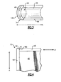
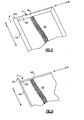
- Figures 4-13 illustrate how a corner is manufactured. With reference to Figure 4 , there is provided first carbon composite fabric layer 60, a portion of which will form first peripheral flange 48 while the other portion will form first axial flange 44.
- First carbon composite fabric layer 60 has first section 70. Along line K, first section 70 is cut creating first portion 82, a tab, and second portion 86, another tab. First portion 82 is now relatively moveable with respect to second portion 86.
- First portion 82 may rotate about axis A while second portion 86 may rotate about axis B, an axis perpendicular to axis A. Second portion 86 is rotated about axis B in the direction of arrow X to the position shown in Figure 5 . As shown in Figure 5 , first portion 82 may be rotated about axis A in the direction of arrow Y to the position shown in Figure 6 . Then, first portion 82 may then be turned in the direction of arrow Z into second portion 86 forming first overlap 80 as shown in Figure 7 . First portion 82 is adhered to second portion 86 with known adhesives thereby forming first corner 74. As can be seen, first corner 74 is made from first axial flange 44 and first peripheral flange 48. In addition, as shown, first carbon composite fabric layer 60 has first plurality of carbon strands 78, say for example, extending generally along axis A.
- Second carbon composite fabric layer 90 has first axial flange 45 and first peripheral flange 49. Ultimately, second carbon composite fabric layer 90 will overlap the first carbon composite fabric layer 60 so that first axial flange 44 overlaps with first axial flange 45 and first peripheral flange 48 will overlap with first peripheral flange 49 to form flanges of multiple carbon composite fabric layers. Referring back to Figure 8 , second section 94 of second carbon composite fabric layer 90 is cut along line L thereby creating third portion 106 and fourth portion 110.
- first axial flange 45 may be turned in the direction of arrow Y while first peripheral flange 49 can be turned in the direction of arrow X and the end of portion 106 turned so that third portion 106 overlaps fourth portion 110 to form second corner 114 as shown in Figure 9 .
- second carbon composite fabric layer 90 has a second plurality of carbon strands 98, say for example, generally extending along axis B.
- second carbon composite fabric layer 90 is layered over first carbon composite fabric layer 60 such that first plurality of carbon strands 78 of first carbon composite fabric layer 60 are transverse to second plurality of carbon strands 98. In this way, first plurality of carbon strands 78 lays across second plurality of carbon strands 98 to create a stronger duct body 36.
- first overlap 80 extends along first axis B while second overlap 102 extends along second axis A.
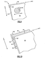
- second carbon composite fabric layer 90 By layering second carbon composite fabric layer 90 onto first carbon composite fabric layer 60 in this way, first corner 74 may be layered onto second corner 114 so that first overlap 80 is displaced from second overlap 102 as shown in Figure 11 .
- the corner of duct body 36 is strengthened. Excess material may be machined off or otherwise removed at locations H and I so that duct body 36 conforms to specification.
- the layering of each carbon composite fabric layer can occur in the manner described above with alternating overlaps and having carbon strands of each layer oriented differently from each other, thereby producing a strong duct body 36.
- first carbon composite fabric layer 60 and second carbon composite fabric layer 90 the layering of carbon composite fabric layers, such as first carbon composite fabric layer 60 and second carbon composite fabric layer 90, occurs on male mold 120, which is shaped in a semi-cylindrical fashion in the desired shape of duct body 36.
- first carbon composite fabric layer 60 is darted, cut, along first peripheral flange 48 along lines M thereby allowing first carbon composite fabric layer 60 to curl over male mold 120.
- Other layers are likewise darted along peripheral flanges.
- First carbon composite fabric layer 60 is layered onto male mold 120 followed by second carbon composite fabric layer 90 in the direction of arrow G.
- Female mold 130 may be used to form second duct body portion 68 in the same manner as first duct body portion 64 as shown in Figure 12 .
- layers of carbon composite fabric such as third carbon composite fabric layer 134 and fourth carbon composite fabric layer 138 are disposed into female mold 130.
Landscapes
- Engineering & Computer Science (AREA)
- General Engineering & Computer Science (AREA)
- Mechanical Engineering (AREA)
- Chemical & Material Sciences (AREA)
- Composite Materials (AREA)
- Combustion & Propulsion (AREA)
- Laminated Bodies (AREA)
- Structures Of Non-Positive Displacement Pumps (AREA)
- Rigid Pipes And Flexible Pipes (AREA)
Claims (17)
- Verfahren zum Herstellen einer Kohlenstoff-Verbundkanalanordnung (20), das folgende Schritte aufweist:a) Bereitstellen einer ersten Kohlenstoff-Verbundtextilschicht (60), die einen ersten Abschnitt (70) aufweist;b) Formen des ersten Abschnitts zu einem ersten Bereich (82) und einem zweiten Bereich (86), wobei der erste Bereich relativ zu dem zweiten Bereich separat beweglich ist;c) überlappendes Anordnen des ersten Bereichs (82) auf dem zweiten Bereich (86), um einen ersten Eckbereich (74) der ersten Kohlenstoff-Verbundtextilschicht (60) zu bilden; undd) Formen der ersten Kohlenstoff-Verbundtextilschicht (60) zu wenigstens einem Bereich eines Kanalkörpers (36) einer sich entlang einer Achse (A) erstreckenden Gasturbinenmaschine, wobei der erste Bereich (82) und der zweite Bereich (86) einen axialen Flansch (44) und einen peripheren Flansch (48) des Kanals bilden, wobei sich der axiale Flansch (44) entlang der Achse (A) erstreckt und sich der periphere Flansch (48) quer zu der Achse (A) erstreckt.
- Herstellungsverfahren nach Anspruch 1,
wobei der Kanal eine Öffnung (40) bildet, wobei sich der periphere Flansch (48) quer zu der Achse (A) um die Öffnung (40) erstreckt. - Herstellungsverfahren nach Anspruch 1 oder 2,
das folgende Schritte aufweist:e) Bereitstellen einer zweiten Kohlenstoff-Verbundtextilschicht (90), die einen zweiten Abschnitt (94) aufweist;f) Formen des zweiten Abschnitts zu einem dritten Bereich (106) und einem vierten Bereich (110), wobei der dritte Bereich relativ zu dem vierten Bereich separat beweglich ist;g) überlappendes Anordnen des dritten Bereichs (106) auf dem vierten Bereich (110), um einen zweiten Eckbereich (114) der zweiten Verbundtextilschicht (90) zu bilden; undh) Schichten der zweiten Kohlenstoff-Verbundtextilschicht (90) auf die erste Kohlenstoff-Verbundtextilschicht (60), so dass der zweite Eckbereich (114) den ersten Eckbereich (74) überlappt. - Verfahren nach Anspruch 3,
wobei der erste Bereich (82) und der zweite Bereich (86) eine erste Überlappung (80) bilden und wobei der dritte Bereich (106) und der vierte Bereich (110) eine zweite Überlappung (102) bilden, wobei der zweite Eckbereich (114) den ersten Eckbereich (74) derart überlappt, dass die erste Überlappung (80) gegenüber der zweiten Überlappung (102) verschoben ist. - Verfahren nach Anspruch 4,
das folgenden Schritt aufweist:i) Eliminieren wenigstens eines Teils von einer der ersten Überlappung (80) und der zweiten Überlappung (102). - Verfahren nach Anspruch 3, 4 oder 5,
wobei die erste Kohlenstoff-Verbundtextilschicht (60) eine erste Mehrzahl von Kohlenstoffsträngen (78) aufweist, die sich im Allgemeinen entlang einer ersten Kohlenstoffstrangachse erstrecken, und die zweite Kohlenstoff-Verbundtextilschicht (90) eine zweite Mehrzahl von Kohlenstoffsträngen (98) aufweist, die sich im Allgemeinen entlang einer zweiten Kohlenstoffstrangachse erstrecken, wobei die zweite Kohlenstoff-Verbundtextilschicht (90) derart auf die erste Kohlenstoff-Verbundtextilschicht (60) geschichtet ist, dass die erste Kohlenstoffstrangachse quer zu der zweiten Kohlenstoffstrangachse ist. - Kohlenstoff-Verbundkanalanordnung (20), aufweisend:einen Kanalkörper (36) mit einer Öffnung (40), wobei sich der Kanalkörper (36) entlang einer Achse (A) erstreckt und sich die Öffnung (40) quer zu der Achse erstreckt;wobei der Kanalkörper (36) eine erste Kohlenstoff-Verbundtextilschicht (60) aufweist; undwobei der Kanalkörper (36) einen sich entlang der Achse (A) erstreckenden ersten ersten axialen Flansch (44) und einen sich entlang der Öffnung (40) erstreckenden ersten peripheren Flansch (48) aufweist, wobei das Kohlenstoff-Verbundtextil sich in dem ersten axialen Flansch (44) und dem ersten peripheren Flansch (48) überlappt,um einen Eckbereich (74) der ersten Kohlenstoff-Verbundtextilschicht (60) zu bilden.
- Kohlenstoff-Verbundkanalanordnung nach Anspruch 7,
mit einer zweiten Kohlenstoff-Verbundtextilschicht (90), die auf der ersten Kohlenstoff-Verbundtextilschicht (60) angeordnet ist. - Kohlenstoff-Verbundkanalanordnung nach Anspruch 8,
wobei die erste Kohlenstoff-Verbundtextilschicht (60) eine erste Mehrzahl von Kohlenstoffsträngen (78) aufweist, die sich im Allgemeinen entlang einer ersten Kohlenstoffstrangachse erstrecken, und die zweite Kohlenstoff-Verbundtextilschicht (90) eine zweite Mehrzahl von Kohlenstoffsträngen (98) aufweist, die sich im Allgemeinen entlang einer zweiten Kohlenstoffstrangachse erstrecken, wobei die zweite Kohlenstoff-Verbundtextilschicht (90) derart auf die erste Kohlenstoff-Verbundtextilschicht (60) geschichtet ist, dass die erste Kohlenstoffstrangachse quer zu der zweiten Kohlenstoffstrangachse ist. - Kohlenstoff-Verbundanordnung nach Anspruch 7, 8 oder 9, wobei der Kanalkörper (36) einen ersten Kanalkörperbereich (82) und einen zweiten Kanalkörperbereich (86) aufweist, wobei der erste Kanalkörperbereich (82) den ersten axialen Flansch (44) bildet und der zweite Kanalkörperbereich (86) einen zweiten axialen Flansch (52) bildet, wobei der erste Kanalkörperbereich (82) entlang des ersten axialen Flansches (44) und des zweiten axialen Flansches (52) mit dem zweiten Kanalkörperbereich (86) selektiv zusammenwirken kann.
- Kohlenstoff-Verbundanordnung nach einem der Ansprüche 7 bis 10, wobei der zweite Kanalkörperbereich (86) einen zweiten peripheren Flansch (56) aufweist, der sich entlang der Öffnung (40) erstreckt, wobei der erste periphere Flansch (44) mit dem zweiten peripheren Flansch (56) selektiv zusammenwirken kann.
- Kohlenstoff-Verbundanordnung nach einem der Ansprüche 7 bis 11, wobei der Kanalkörper (36) mindestens einen Bereich eines Umgehungskanals (20) für eine Turbinenmaschine (10) aufweist.
- Kohlenstoff-Verbundanordnung nach Anspruch 12,
die einen Zwischengehäuse-Kanal (28) in Verbindung mit dem Kanalkörper (36) aufweist. - Kohlenstoff-Verbundanordnung nach Anspruch 12 oder 13,
mit einem vorderen Nachbrennerkanal (32) in Verbindung mit dem Kanalkörper (36). - Kohlenstoff-Verbundkanalanordnung nach Anspruch 10,
wobei der Kanalkörper (36) mindestens einen Bereich eines Umgehungskanals (20) für eine Turbinenmaschine (10) aufweist; und wobei der Kanalkörper (36) einen ersten Kanalkörperbereich (82) und einen zweiten Kanalkörperbereich (86) aufweist, wobei der erste Kanalkörperbereich (82) den ersten axialen Flansch (44) bildet und der zweite Kanalkörperbereich (86) einen zweiten axialen Flansch (52) bildet, wobei der erste Kanalkörperbereich (82) entlang des ersten axialen Flansches (44) und entlang des zweiten axialen Flansches (52) mit dem zweiten Kanalkörperbereich (86) selektiv zusammenwirken kann, wobei der zweite Kanalkörperbereich (86) einen zweiten peripheren Flansch (56) aufweist, der sich entlang der Öffnung (40) erstreckt, wobei der erste periphere Flansch (48) mit dem zweiten peripheren Flansch (56) selektiv zusammenwirken kann. - Kohlenstoff-Verbundkanälanordnung nach Anspruch 15,
mit einer zweiten Kohlenstoff-Verbundtextilschicht (90), die auf der ersten Kohlenstoff-Verbundtextilschicht (60) angeordnet ist. - Kohlenstoff-Verbundkanalanordnung nach Anspruch 16,
wobei die erste Kohlenstoff-Verbundtextilschicht (60) eine erste Mehrzahl von Kohlenstoffsträngen (78) aufweist, die sich im Allgemeinen entlang einer ersten Kohlenstoffstrangachse erstrecken, und die zweite Kohlenstoff-Verbundtextilschicht (90) eine zweite Mehrzahl von Kohlenstoffsträngen (98) aufweist, die sich im Allgemeinen entlang einer zweiten Kohlenstoffstrangachse erstrecken, wobei die zweite Kohlenstoff-Verbundtextilschicht (90) derart auf die erste Kohlenstoff-Verbundtextilschicht (60) geschichtet ist, dass die erste Kohlenstoffstrangachse quer zu der zweiten Kohlenstoffstrangachse ist.
Applications Claiming Priority (1)
| Application Number | Priority Date | Filing Date | Title |
|---|---|---|---|
| US11/761,489 US7963098B2 (en) | 2007-06-12 | 2007-06-12 | Composite duct assembly |
Publications (3)
| Publication Number | Publication Date |
|---|---|
| EP2002965A2 EP2002965A2 (de) | 2008-12-17 |
| EP2002965A3 EP2002965A3 (de) | 2011-08-31 |
| EP2002965B1 true EP2002965B1 (de) | 2013-01-02 |
Family
ID=39771953
Family Applications (1)
| Application Number | Title | Priority Date | Filing Date |
|---|---|---|---|
| EP08251426A Active EP2002965B1 (de) | 2007-06-12 | 2008-04-14 | Verbundrohranordnung und Verfahren zu deren Herstellung |
Country Status (2)
| Country | Link |
|---|---|
| US (2) | US7963098B2 (de) |
| EP (1) | EP2002965B1 (de) |
Families Citing this family (1)
| Publication number | Priority date | Publication date | Assignee | Title |
|---|---|---|---|---|
| US8685302B2 (en) | 2012-02-20 | 2014-04-01 | Honeywell International Inc. | Monolithic acoustically-treated composite structures and methods for fabricating the same |
Family Cites Families (29)
| Publication number | Priority date | Publication date | Assignee | Title |
|---|---|---|---|---|
| US3771820A (en) * | 1972-05-22 | 1973-11-13 | Lockheed Aircraft Corp | Adhesive bonded split sleeve coupling for pipes and tubular members |
| US4005822A (en) * | 1975-12-22 | 1977-02-01 | Rohr Industries, Inc. | Fan duct thrust reverser |
| US4062917A (en) * | 1976-11-05 | 1977-12-13 | Burlington Industries, Inc. | Method of molding resin-impregnated fabric layer using release sheet and absorbent sheet inside evacuated bag |
| US4328981A (en) * | 1980-09-19 | 1982-05-11 | Greene Jr Carl B | Duct structure with reinforced end flanges |
| GB2093125B (en) * | 1981-02-14 | 1984-04-18 | Rolls Royce | Gas turbine engine casing |
| US4865267A (en) * | 1988-02-25 | 1989-09-12 | Sundstrand Corporation | Ram air flow system for aircraft |
| US5083426A (en) | 1989-10-02 | 1992-01-28 | Rohr Industries, Inc. | Integrated engine shroud for gas turbine engines |
| GB9014381D0 (en) | 1990-06-28 | 1990-08-22 | Short Brothers Plc | A composite structural component |
| DE4129959A1 (de) * | 1991-09-10 | 1993-03-11 | Menzolit Gmbh | Verfahren und fasermatte zur herstellung eines faserverstaerkten kunststoff-formteils sowie ein kunststoff-formteil |
| FR2691922B1 (fr) * | 1992-06-03 | 1994-07-22 | Snecma | Procede et dispositif de moulage de piece en materiau composite constituee de deux secteurs. |
| FR2699449B1 (fr) | 1992-12-17 | 1995-03-24 | Eurocopter France | Procédé de fabrication de liaisons en matériau composite de structures en forme de treillis ou d'éléments de treillis, et treillis obtenus par ce procédé. |
| US6991124B1 (en) * | 1995-09-25 | 2006-01-31 | Alliedsignal Inc. | Blast resistant and blast directing containers and methods of making |
| US7498509B2 (en) * | 1995-09-28 | 2009-03-03 | Fiberspar Corporation | Composite coiled tubing end connector |
| JP3687166B2 (ja) * | 1995-12-28 | 2005-08-24 | 信越半導体株式会社 | 単結晶引上げ装置の整流筒昇降方法、及び単結晶引上げ装置の整流筒昇降機構 |
| US6194662B1 (en) * | 1998-10-27 | 2001-02-27 | Public Service Electric And Gas Company | Adjustable cover for outdoor electrical substations |
| US6439840B1 (en) * | 2000-11-30 | 2002-08-27 | Pratt & Whitney Canada Corp. | Bypass duct fan noise reduction assembly |
| US6532731B2 (en) * | 2001-06-22 | 2003-03-18 | Gaylen Springer | Turbofan engine having central bypass duct and peripheral core engine |
| US6554564B1 (en) * | 2001-11-14 | 2003-04-29 | United Technologies Corporation | Reduced noise fan exit guide vane configuration for turbofan engines |
| US6732502B2 (en) * | 2002-03-01 | 2004-05-11 | General Electric Company | Counter rotating aircraft gas turbine engine with high overall pressure ratio compressor |
| US7112054B2 (en) * | 2002-08-09 | 2006-09-26 | The Boeing Company | Consolidation joining of thermoplastic laminate ducts |
| US6968674B2 (en) * | 2003-01-28 | 2005-11-29 | General Electric Company | Methods and apparatus for operating gas turbine engines |
| US7055306B2 (en) * | 2003-04-30 | 2006-06-06 | Hamilton Sundstrand Corporation | Combined stage single shaft turbofan engine |
| US6901739B2 (en) * | 2003-10-07 | 2005-06-07 | General Electric Company | Gas turbine engine with variable pressure ratio fan system |
| US7192462B2 (en) * | 2004-04-14 | 2007-03-20 | Aerospace Filtration Systems, Inc. | Engine air filter and sealing system |
| JP4299211B2 (ja) * | 2004-08-31 | 2009-07-22 | 住友電装株式会社 | プロテクタ |
| US7140174B2 (en) * | 2004-09-30 | 2006-11-28 | General Electric Company | Methods and apparatus for assembling a gas turbine engine |
| EP1929601B1 (de) * | 2005-09-05 | 2010-07-14 | Guarduct (Proprietary) Limited | Durchgangsbaugruppen für wohnungsdienstkabel, rohre und dergleichen und komponenten dafür |
| US20080001396A1 (en) * | 2006-04-07 | 2008-01-03 | Nish Randy W | Pipe coupling and method |
| US8966754B2 (en) * | 2006-11-21 | 2015-03-03 | General Electric Company | Methods for reducing stress on composite structures |
-
2007
- 2007-06-12 US US11/761,489 patent/US7963098B2/en active Active
-
2008
- 2008-04-14 EP EP08251426A patent/EP2002965B1/de active Active
-
2011
- 2011-04-26 US US13/094,037 patent/US8973263B2/en active Active
Also Published As
| Publication number | Publication date |
|---|---|
| US20080308048A1 (en) | 2008-12-18 |
| EP2002965A3 (de) | 2011-08-31 |
| US20110203725A1 (en) | 2011-08-25 |
| US7963098B2 (en) | 2011-06-21 |
| EP2002965A2 (de) | 2008-12-17 |
| US8973263B2 (en) | 2015-03-10 |
Similar Documents
| Publication | Publication Date | Title |
|---|---|---|
| US10260374B2 (en) | Composite flange from braided preform | |
| EP2295723B1 (de) | Verbundstoffschaufel bestehend aus einem dreidimensionalen genähten Kern und aus einer Haut aus Komposite und Herstellungsverfahren dieser Schaufel | |
| EP3124748B1 (de) | Leitschaufelpassage | |
| JP5588103B2 (ja) | ほぼ円筒形の複合材物品及びファンケーシング | |
| RU2598936C1 (ru) | Цилиндрический кожух и способ изготовления цилиндрического кожуха | |
| US11913346B2 (en) | Multiple layer structure | |
| EP2971549B1 (de) | Laufschaufel eines gasturbinentriebwerks, zugehöriges gasturbinentriebwerk und herstellungsverfahren | |
| US11732597B2 (en) | Double box composite seal assembly with insert for gas turbine engine | |
| US20260117663A1 (en) | Turbine engine with composite airfoil having a non-metallic leading edge protective wrap | |
| US20160230569A1 (en) | Cmc airfoil with sharp trailing edge and method of making same | |
| EP3913197B1 (de) | Anordnungen zur übertragung von druckbelastungen in flanschen von gasturbinenbauteilen aus verbundwerkstoff | |
| US11370714B2 (en) | Integral ceramic matrix composite fastener with polymer rigidization | |
| EP3124751B1 (de) | Leitschaufelpassage | |
| EP3623611B1 (de) | Schubumkehrerkaskadenanordnung und verfahren zur herstellung davon | |
| US20090060733A1 (en) | Overlap interface for a gas turbine engine composite engine case | |
| US10047609B2 (en) | Airfoil array with airfoils that differ in geometry according to geometry classes | |
| US7963098B2 (en) | Composite duct assembly | |
| EP2966270B1 (de) | Komponente | |
| US12397512B2 (en) | Forming duct structure with overbraided woven fiber sleeve | |
| US20240227334A1 (en) | Forming duct structure with overbraided woven fiber sleeve | |
| EP2444239B1 (de) | Iso-Rasterverbundkomponente |
Legal Events
| Date | Code | Title | Description |
|---|---|---|---|
| PUAI | Public reference made under article 153(3) epc to a published international application that has entered the european phase |
Free format text: ORIGINAL CODE: 0009012 |
|
| AK | Designated contracting states |
Kind code of ref document: A2 Designated state(s): AT BE BG CH CY CZ DE DK EE ES FI FR GB GR HR HU IE IS IT LI LT LU LV MC MT NL NO PL PT RO SE SI SK TR |
|
| AX | Request for extension of the european patent |
Extension state: AL BA MK RS |
|
| PUAL | Search report despatched |
Free format text: ORIGINAL CODE: 0009013 |
|
| AK | Designated contracting states |
Kind code of ref document: A3 Designated state(s): AT BE BG CH CY CZ DE DK EE ES FI FR GB GR HR HU IE IS IT LI LT LU LV MC MT NL NO PL PT RO SE SI SK TR |
|
| AX | Request for extension of the european patent |
Extension state: AL BA MK RS |
|
| RIC1 | Information provided on ipc code assigned before grant |
Ipc: B29C 70/30 20060101AFI20110725BHEP |
|
| 17P | Request for examination filed |
Effective date: 20120229 |
|
| AKX | Designation fees paid |
Designated state(s): DE GB |
|
| GRAC | Information related to communication of intention to grant a patent modified |
Free format text: ORIGINAL CODE: EPIDOSCIGR1 |
|
| GRAP | Despatch of communication of intention to grant a patent |
Free format text: ORIGINAL CODE: EPIDOSNIGR1 |
|
| RIN1 | Information on inventor provided before grant (corrected) |
Inventor name: RIVERA, ANTHONY |
|
| GRAS | Grant fee paid |
Free format text: ORIGINAL CODE: EPIDOSNIGR3 |
|
| GRAA | (expected) grant |
Free format text: ORIGINAL CODE: 0009210 |
|
| AK | Designated contracting states |
Kind code of ref document: B1 Designated state(s): DE GB |
|
| REG | Reference to a national code |
Ref country code: GB Ref legal event code: FG4D |
|
| REG | Reference to a national code |
Ref country code: DE Ref legal event code: R096 Ref document number: 602008021311 Country of ref document: DE Effective date: 20130228 |
|
| PLBE | No opposition filed within time limit |
Free format text: ORIGINAL CODE: 0009261 |
|
| STAA | Information on the status of an ep patent application or granted ep patent |
Free format text: STATUS: NO OPPOSITION FILED WITHIN TIME LIMIT |
|
| 26N | No opposition filed |
Effective date: 20131003 |
|
| REG | Reference to a national code |
Ref country code: DE Ref legal event code: R097 Ref document number: 602008021311 Country of ref document: DE Effective date: 20131003 |
|
| REG | Reference to a national code |
Ref country code: DE Ref legal event code: R082 Ref document number: 602008021311 Country of ref document: DE Representative=s name: SCHMITT-NILSON SCHRAUD WAIBEL WOHLFROM PATENTA, DE |
|
| REG | Reference to a national code |
Ref country code: DE Ref legal event code: R082 Ref document number: 602008021311 Country of ref document: DE Representative=s name: SCHMITT-NILSON SCHRAUD WAIBEL WOHLFROM PATENTA, DE Ref country code: DE Ref legal event code: R081 Ref document number: 602008021311 Country of ref document: DE Owner name: UNITED TECHNOLOGIES CORP. (N.D.GES.D. STAATES , US Free format text: FORMER OWNER: UNITED TECHNOLOGIES CORPORATION, HARTFORD, CONN., US |
|
| REG | Reference to a national code |
Ref country code: DE Ref legal event code: R081 Ref document number: 602008021311 Country of ref document: DE Owner name: RAYTHEON TECHNOLOGIES CORPORATION (N.D.GES.D.S, US Free format text: FORMER OWNER: UNITED TECHNOLOGIES CORP. (N.D.GES.D. STAATES DELAWARE), FARMINGTON, CONN., US Ref country code: DE Ref legal event code: R081 Ref document number: 602008021311 Country of ref document: DE Owner name: RTX CORPORATION (N.D.GES.D. STAATES DELAWARE),, US Free format text: FORMER OWNER: UNITED TECHNOLOGIES CORP. (N.D.GES.D. STAATES DELAWARE), FARMINGTON, CONN., US |
|
| P01 | Opt-out of the competence of the unified patent court (upc) registered |
Effective date: 20230519 |
|
| PGFP | Annual fee paid to national office [announced via postgrant information from national office to epo] |
Ref country code: DE Payment date: 20250319 Year of fee payment: 18 |
|
| REG | Reference to a national code |
Ref country code: DE Ref legal event code: R081 Ref document number: 602008021311 Country of ref document: DE Owner name: RTX CORPORATION (N.D.GES.D. STAATES DELAWARE),, US Free format text: FORMER OWNER: RAYTHEON TECHNOLOGIES CORPORATION (N.D.GES.D.STAATES DELAWARE), ARLINGTON, VA, US |
|
| PGFP | Annual fee paid to national office [announced via postgrant information from national office to epo] |
Ref country code: GB Payment date: 20260319 Year of fee payment: 19 |