EP2441663A1 - Submarine - Google Patents
Submarine Download PDFInfo
- Publication number
- EP2441663A1 EP2441663A1 EP11184525A EP11184525A EP2441663A1 EP 2441663 A1 EP2441663 A1 EP 2441663A1 EP 11184525 A EP11184525 A EP 11184525A EP 11184525 A EP11184525 A EP 11184525A EP 2441663 A1 EP2441663 A1 EP 2441663A1
- Authority
- EP
- European Patent Office
- Prior art keywords
- submarine
- module
- weapon
- pressure
- tubes
- Prior art date
- Legal status (The legal status is an assumption and is not a legal conclusion. Google has not performed a legal analysis and makes no representation as to the accuracy of the status listed.)
- Granted
Links
Images


Classifications
-
- B—PERFORMING OPERATIONS; TRANSPORTING
- B63—SHIPS OR OTHER WATERBORNE VESSELS; RELATED EQUIPMENT
- B63G—OFFENSIVE OR DEFENSIVE ARRANGEMENTS ON VESSELS; MINE-LAYING; MINE-SWEEPING; SUBMARINES; AIRCRAFT CARRIERS
- B63G8/00—Underwater vessels, e.g. submarines; Equipment specially adapted therefor
- B63G8/28—Arrangement of offensive or defensive equipment
- B63G8/30—Arrangement of offensive or defensive equipment of artillery or missile launching means
-
- B—PERFORMING OPERATIONS; TRANSPORTING
- B63—SHIPS OR OTHER WATERBORNE VESSELS; RELATED EQUIPMENT
- B63G—OFFENSIVE OR DEFENSIVE ARRANGEMENTS ON VESSELS; MINE-LAYING; MINE-SWEEPING; SUBMARINES; AIRCRAFT CARRIERS
- B63G8/00—Underwater vessels, e.g. submarines; Equipment specially adapted therefor
- B63G8/28—Arrangement of offensive or defensive equipment
- B63G8/32—Arrangement of offensive or defensive equipment of torpedo-launching means; of torpedo stores or handlers
-
- B—PERFORMING OPERATIONS; TRANSPORTING
- B63—SHIPS OR OTHER WATERBORNE VESSELS; RELATED EQUIPMENT
- B63G—OFFENSIVE OR DEFENSIVE ARRANGEMENTS ON VESSELS; MINE-LAYING; MINE-SWEEPING; SUBMARINES; AIRCRAFT CARRIERS
- B63G8/00—Underwater vessels, e.g. submarines; Equipment specially adapted therefor
- B63G8/04—Superstructure
-
- B—PERFORMING OPERATIONS; TRANSPORTING
- B63—SHIPS OR OTHER WATERBORNE VESSELS; RELATED EQUIPMENT
- B63G—OFFENSIVE OR DEFENSIVE ARRANGEMENTS ON VESSELS; MINE-LAYING; MINE-SWEEPING; SUBMARINES; AIRCRAFT CARRIERS
- B63G8/00—Underwater vessels, e.g. submarines; Equipment specially adapted therefor
- B63G8/28—Arrangement of offensive or defensive equipment
- B63G8/33—Arrangement of offensive or defensive equipment of mine-laying means
-
- F—MECHANICAL ENGINEERING; LIGHTING; HEATING; WEAPONS; BLASTING
- F41—WEAPONS
- F41A—FUNCTIONAL FEATURES OR DETAILS COMMON TO BOTH SMALLARMS AND ORDNANCE, e.g. CANNONS; MOUNTINGS FOR SMALLARMS OR ORDNANCE
- F41A11/00—Assembly or disassembly features; Modular concepts; Articulated or collapsible guns
- F41A11/02—Modular concepts, e.g. weapon-family concepts
-
- F—MECHANICAL ENGINEERING; LIGHTING; HEATING; WEAPONS; BLASTING
- F41—WEAPONS
- F41F—APPARATUS FOR LAUNCHING PROJECTILES OR MISSILES FROM BARRELS, e.g. CANNONS; LAUNCHERS FOR ROCKETS OR TORPEDOES; HARPOON GUNS
- F41F3/00—Rocket or torpedo launchers
- F41F3/04—Rocket or torpedo launchers for rockets
- F41F3/073—Silos for rockets, e.g. mounting or sealing rockets therein
-
- F—MECHANICAL ENGINEERING; LIGHTING; HEATING; WEAPONS; BLASTING
- F41—WEAPONS
- F41F—APPARATUS FOR LAUNCHING PROJECTILES OR MISSILES FROM BARRELS, e.g. CANNONS; LAUNCHERS FOR ROCKETS OR TORPEDOES; HARPOON GUNS
- F41F3/00—Rocket or torpedo launchers
- F41F3/04—Rocket or torpedo launchers for rockets
- F41F3/077—Doors or covers for launching tubes
-
- F—MECHANICAL ENGINEERING; LIGHTING; HEATING; WEAPONS; BLASTING
- F41—WEAPONS
- F41F—APPARATUS FOR LAUNCHING PROJECTILES OR MISSILES FROM BARRELS, e.g. CANNONS; LAUNCHERS FOR ROCKETS OR TORPEDOES; HARPOON GUNS
- F41F3/00—Rocket or torpedo launchers
- F41F3/08—Rocket or torpedo launchers for marine torpedoes
- F41F3/10—Rocket or torpedo launchers for marine torpedoes from below the surface of the water
-
- B—PERFORMING OPERATIONS; TRANSPORTING
- B63—SHIPS OR OTHER WATERBORNE VESSELS; RELATED EQUIPMENT
- B63B—SHIPS OR OTHER WATERBORNE VESSELS; EQUIPMENT FOR SHIPPING
- B63B1/00—Hydrodynamic or hydrostatic features of hulls or of hydrofoils
- B63B1/02—Hydrodynamic or hydrostatic features of hulls or of hydrofoils deriving lift mainly from water displacement
- B63B1/04—Hydrodynamic or hydrostatic features of hulls or of hydrofoils deriving lift mainly from water displacement with single hull
- B63B1/06—Shape of fore part
Definitions
- the invention relates to a submarine with the features specified in the preamble of claim 1.
- torpedoes In military submarines, usually torpedoes, rockets and underwater mines are carried as weapons. It is known to store these weapons within the pressure hull of such submarines typically in so-called torpedo tubes. Especially with submarines with relatively small size, the stored weapons reduce the already limited space in the pressure hull.
- the arms takeover in the submarine can be done on trained on the upper deck of the submarine weapons Mattermaschinenmelmeluk. It is particularly expensive in torpedoes, which can be more than 7 meters long and weigh almost 2,000 kilograms.
- a weapons transfer platform must be set up on the upper deck of the submarine and a weapons loading device must be set up in the pressure hull and dismantled again after loading.
- the omission of the weapons from the submarine is usually carried out through the Druckêtdung weapon tubes.
- the outside of the pressure hull arranged ends of these gun barrels are pressure-tightly closed with muzzle flaps, while the arranged inside the pressure hull ends of the weapon tubes are sealed pressure-tight by bottom closures.
- When draining a gun from a gun barrel make sure that when opened Muzzle flap of the bottom closure of the barrel is closed.
- the mouth flaps of the weapon tubes are blocked with the bottom closures.
- a failure of the blockage with simultaneous opening of the mouth flap and the bottom closure leads to a water ingress into the pressure hull, which in the worst case can lead to the loss of the submarine.
- a further source of danger are the torpedoes stored in the gun barrels.
- Out DE 24 54 738 A1 is a submarine known in which the weapon tubes are located completely outside the pressure hull.
- the armament does not affect the space available in the pressure hull in this submarine.
- reloading the weapon tubes proves to be particularly costly, since the weapon tubes are located below the waterline of the submarine that has surfaced, so that the reloading of the weapon tubes must either be done in a dock or a diving operation required.
- the present invention seeks to provide a submarine, which allows over the prior art improved weapon storage and weapons acquisition.
- the submarine according to the invention has a pressure body in the usual way. Outside the pressure hull an armament module for storing and ejecting several weapons is arranged in front of the bug workedem end. In this region of the pressure body, an outer skin of the submarine is preferably arranged outside of the pressure body, wherein the armament module is mounted in the freely flooded space between the pressure body and the outer skin.
- the basic idea of the invention is to design the weapon module as a detachable unit. This measure makes it possible to detach the armament module from the boat structure and to spend, for example with a crane or other suitable hoist, on a submarine vessel supporting the submarine or ashore. A loading, component inspection or maintenance of the weapon module is thereby much easier and faster than directly on the submarine feasible.
- an armament module removed from the submarine can be replaced directly with a pre-deployed other and ready-to-use arming module, so that the weapon takeover time in the submarine according to the invention is decisively shortened compared to the previously known submarines.
- different arming modules can be provided with regard to the arming, which are specially adapted to the respective operational profile of the submarine.
- the submarine z. B. if it is to be used only for laying underwater mines, be equipped with a weapon module, the priority or is exclusively equipped with underwater mines and / or designed specifically for the exposure of underwater mines. If the submarine is to be used for discontinuation of special forces, for example, a weapon module can be used, which in addition to the armament also has a storage space for items to be upgraded of the emergency forces to be dropped.
- the replacement of the weapon module is further facilitated if, as is preferred, it is located in an area above the waterline when the submarine has surfaced.
- This arrangement of the arming module makes it possible to detach the armament module from the boat structure without a diving insert, and then to remove it from the boat structure or to equip the submarine with the arming module without a diving insert.
- the arming module forms part of the outer skin of the submarine.
- the arming module preferably has an outer lining whose shape corresponds to the shape of the adjoining outer skin region. In this way, a substantially seamless and therefore streamlined and low-signature transition from the armament module to the adjacent outer skin is created.
- the arming module may form a portion of a walk-on upper deck of the submarine.
- the armament module can be integrated in the upper deck or, in a preferred embodiment, form a front end area of the upper deck facing away from a tower of the submarine, which is particularly advantageous when the armament module is provided for deploying torpedoes.
- the armament module preferably has a plurality of weapon tubes mounted in a shock-resistant manner in a support structure.
- the support structure is expediently designed in such a way that the largest possible number of weapon tubes are arranged next to and above one another in the arming module.
- the weapon tubes can essentially correspond to the weapon tubes, which are guided in the hitherto known submarines through the Druckismewandung.
- the weapon tubes are equipped with all required for deploying a weapon mechanical and / or hydraulic devices.
- both ends of the weapon tubes can be closed pressure-tight with flaps.
- the weapon tubes are designed as open tubes, in which a front in the discharge direction of the weapon opening with a mouth flap and a rear opening are closed with a bottom flap.
- the mouth flap and the bottom flap are coupled for movement via a linkage in such a way that both flaps for dispensing a weapon stored in the weapon barrel can be opened at the same time, which advantageously results in unimpeded inflow of water into the weapon barrel when the weapon exits or when the weapon is ejected from the weapon barrel allows.
- the weapon tubes can also be filled with a suitable liquid, for example glycol.
- a suitable liquid for example glycol.
- the weapon tubes each have loading and venting or loading and drainage facilities. These devices are preferably controllable valve arrangements by means of which the weapon tubes can be vented and irrigated before the application of the weapons stored therein and can be dehydrated again when submarine emerged.
- An opening mechanism for opening the mouth and bottom flaps of the weapon tubes as well as an optional starting device for discharging the weapons from the weapon tubes can be hydraulically actuated.
- a hydraulic system of the weapon module can be advantageously connected by means of quick-release couplings to a boat-side hydraulic system.
- Electrical devices of the weapon module are preferably connected in the submarine according to the invention in a simple manner by means of pressure-tight connectors to the boat electrical system.
- Fig. 1 and 3 is a front part of a submarine shown.
- the submarine has a pressure body 2.
- the pressure body 2 is surrounded by an outer skin 4.
- the outer skin 4 is spaced from the pressure body 2, so that between the pressure body 2 and the outer skin 4 is a freely interspersed gap 6.
- Fig. 3 the pressure hull 2 is not covered with the outer skin 4 in an area in front of his bow-side end, which is above the waterline when surfaced submarine.
- a removable armament module 10 or 10 ' is integrated.
- the armament module 10 or 10 ' is placed on a supporting structure 12, which is rigidly connected to the pressure body 2 and extends from the pressure body 2 parallel to a longitudinal axis A of the pressure body in the direction of arranged in front of the pressure body 2 outer skin 4.
- armament module 10 Both in the Fig. 1 and 2 illustrated armament module 10 as well as in the Fig. 3 and 4 shown armament module 10 'are not placed directly on the structure 12 but shock elastic on damping elements 14, which are arranged in formed at the top of the structure 12 wells 16.
- guide pins 20 are provided on the underside of the armament modules 10 and 10', which engage corresponding recesses formed on the storage foundation 18 when the arming module 10 or 10 'is placed ,
- outer damping elements 14 locking elements 22 are arranged, the locking elements 24 provided on the arming modules 10 and 10 'form locking devices with which the arming module 10 or 10' is firmly connected to the supporting structure 12.
- the armament modules 10 and 10 'each have an outer panel 26 corresponding to the outer skin 4 of the submarine such that the outer surface of the outer panel 26 is flush with the outer side of the outer skin 4 adjacent thereto.
- the outer lining 26 also forms part of the outer skin 4 of the submarine.
- the top of the outer panel 26 forms part of the upper deck 8.
- a gap existing at the transition from the outer panel 26 of the arming module 10 or 10 'to the outer skin 4 is closed with a profile rubber 28 encircling the outer edge of the outer panel 26.
- armament module 10 extend three spaced juxtaposed support bulkheads 30, 32 and 34 in the direction perpendicular to the storage foundation 18.
- holding means 36 are arranged, which serve for the positive attachment of the outer lining 26.
- the supporting bulkheads 30, 32 and 34 form a support structure for weapon arms 38 mounted in the arming module 10.
- the support bulkheads 30, 32 and 34 each have eleven round openings 40, the arrangement of the openings 40 of the individual support bulkheads being equal.
- the weapon tubes 38 are welded or screwed to the support bulkheads 30, 32 and 34, so that the weapon tubes 38 and the support bulkheads 30, 32 and 34 form a rigid unit.
- the weapon tubes 38 serve primarily for storing and deploying torpedoes. They are constructed to be pressure-resistant, wherein the outlet openings of the weapon tubes 38 facing away from the pressure body 2 are each closed by a mouth flap 42 and the openings of the weapon tubes 38 facing the pressure body 2 are each closed by a bottom flap 44.
- the mouth flaps 42 are each rigidly connected to outer skin flaps 46, which are arranged in front of the weapon tubes 38 and form part of the outer lining 26 of the weapon module 10 and the outer skin 4.
- hydraulic drives 48 for pivoting the mouth flaps 42 are arranged on the weapon tubes 38.
- the mouth flaps 42 are each coupled for movement via a mouth flap lever 50 to a drive shaft 52 of the drive 48.
- the mouth flap 42 is coupled to the bottom flap 44 via a linkage, not shown in the drawing for clarity. If an outlet flap 42 of a weapon barrel 38 is pivoted by means of the drive 48 into an open position, the bottom flap 44 of the respective weapon barrel 38 is pivoted into an open position via the linkage, which during unwinding or ejection of a weapon stored in the weapon barrel 38, an unhindered afterflow of Water allows.
- ventilation valves 54 and loading and drainage valves 56 are provided which are arranged on the individual weapon tubes 38 in each case on the outer lateral surface.
- a plurality of hydraulic accumulators 58 and an electric / hydraulic module control 60 are arranged on the upper side of the pressure body 2. Either the hydraulic accumulator 58 as well as the module control 60 are combined in a shock-elastic manner mounted on damping elements 62 frame 64.
- hydraulic and electrical lines 66 are guided along the weapon tubes 38. The hydraulic lines are connected to the hydraulic accumulators 58 via quick couplings 68 and hose compensators 70 connected therebetween.
- pressure-tight plug connections 72 are provided to connect the electrical lines of the arming module 10 to the module control 60 arranged on the boat side.
- the hydraulic and electrical connection of the pressure accumulator 58 and the module control 60 with the pressure chamber interior takes place via pressure body bushings 74 and 76.
- Another pressure bushing 78 serves to guide data transmission cables into the interior of the pressure body 2.
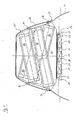
- armament module 10 is used for deploying underwater mines. Similar to the arming module 10, the arming module 10 'has three spaced juxtaposed support bulkheads 80, 82 and 84 that are oriented perpendicular to the storage foundation 18. As with the armament module 10, retaining devices 36 are also arranged on the outer edge of the support bulkheads 80, 82 and 84 of the arming module 10, which are used for the positive fastening of the outer cover 26. Between the support bulkheads 80 and 84 and on the outside of the support bulkheads 80 and 84, weapon tubes 86 are arranged for storage and for discharging underwater mines.
- the individual weapon tubes 86 extend obliquely inclined to one of the two longitudinal sides of the submarine, wherein the outlet openings of the weapon tubes 86 are each formed at the lower end of the weapon tubes. This refinement makes it possible for the underwater mines from the weapon tubes 86 to run off automatically due to gravity.
Landscapes
- Engineering & Computer Science (AREA)
- General Engineering & Computer Science (AREA)
- Mechanical Engineering (AREA)
- Aviation & Aerospace Engineering (AREA)
- Ocean & Marine Engineering (AREA)
- Filling Or Discharging Of Gas Storage Vessels (AREA)
- Aiming, Guidance, Guns With A Light Source, Armor, Camouflage, And Targets (AREA)
- Details Of Aerials (AREA)
Abstract
Description
Die Erfindung betrifft ein Unterseeboot mit den im Oberbegriff des Anspruchs 1 angegebenen Merkmalen.The invention relates to a submarine with the features specified in the preamble of claim 1.
In militärischen Unterseebooten werden üblicherweise Torpedos, Raketen und Unterwasserminen als Bewaffnung mitgeführt. Es ist bekannt, diese Waffen innerhalb der Druckkörper solcher Unterseeboote typischerweise in so genannten Torpedorohren zu lagern. Insbesondere bei Unterseebooten mit verhältnismäßig geringer Größe verringern die gelagerten Waffen das an sich schon eingeschränkte Raumangebot in dem Druckkörper.In military submarines, usually torpedoes, rockets and underwater mines are carried as weapons. It is known to store these weapons within the pressure hull of such submarines typically in so-called torpedo tubes. Especially with submarines with relatively small size, the stored weapons reduce the already limited space in the pressure hull.
Die Waffenübernahme in das Unterseeboot kann über am Oberdeck des Unterseeboots ausgebildetes Waffenübernahmeluk erfolgen. Sie ist speziell bei Torpedos, die mehr als 7 Meter Länge und ein Gewicht von nahezu 2.000 Kilogramm aufweisen können, aufwändig. Hierzu muss auf dem Oberdeck des Unterseeboots eine Waffenübernahmebühne und in dem Druckkörper eine Waffenbeladevorrichtung aufgebaut und nach dem Beladen wieder abgebaut werden.The arms takeover in the submarine can be done on trained on the upper deck of the submarine weapons Übernmelmeluk. It is particularly expensive in torpedoes, which can be more than 7 meters long and weigh almost 2,000 kilograms. For this purpose, a weapons transfer platform must be set up on the upper deck of the submarine and a weapons loading device must be set up in the pressure hull and dismantled again after loading.
Das Auslassen der Waffen aus dem Unterseeboot erfolgt in der Regel über durch die Druckkörperwandung geführte Waffenrohre. Die außerhalb des Druckkörpers angeordneten Enden dieser Waffenrohre werden mit Mündungsklappen druckdicht verschlossen, während die innerhalb des Druckkörpers angeordneten Enden der Waffenrohre mittels Bodenverschlüssen druckdicht verschlossen werden. Beim Auslassen einer Waffe aus einem Waffenrohr ist sicherzustellen, dass bei dann geöffneter Mündungsklappe der Bodenverschluss des Waffenrohrs geschlossen ist. Hierzu sind die Mündungsklappen der Waffenrohre mit den Bodenverschlüssen verblockt. Ein Versagen der Verblockung bei gleichzeitiger Öffnung der Mündungsklappe und des Bodenverschlusses führt zu einem Wassereinbruch in den Druckkörper, der im ungünstigsten Fall zum Verlust des Unterseeboots führen kann. Eine weitere Gefahrenquelle stellen die in den Waffenrohren gelagerten Torpedos dar. Eine Explosion eines in einem Waffenrohr gelagerten Torpedos führt üblicherweise immer zum Verlust eines Unterseeboots. Des Weiteren erweist es sich als nachteilig, dass die durch den Druckkörper geführten Waffenrohre typischerweise starr mit dem Druckkörper verbunden sind, so dass die auf den Druckkörper wirkende Schockbeanspruchung direkt auf die in den Waffenrohren gelagerten Waffen übertragen werden.The omission of the weapons from the submarine is usually carried out through the Druckkörperwandung weapon tubes. The outside of the pressure hull arranged ends of these gun barrels are pressure-tightly closed with muzzle flaps, while the arranged inside the pressure hull ends of the weapon tubes are sealed pressure-tight by bottom closures. When draining a gun from a gun barrel, make sure that when opened Muzzle flap of the bottom closure of the barrel is closed. For this purpose, the mouth flaps of the weapon tubes are blocked with the bottom closures. A failure of the blockage with simultaneous opening of the mouth flap and the bottom closure leads to a water ingress into the pressure hull, which in the worst case can lead to the loss of the submarine. A further source of danger are the torpedoes stored in the gun barrels. An explosion of a torpedo stored in a gun barrel usually always leads to the loss of a submarine. Furthermore, it proves to be disadvantageous that the guided through the pressure hull weapon tubes are typically rigidly connected to the pressure body, so that the pressure acting on the pressure body shock load are transmitted directly to the weapons stored in the weapons tubes.
Aus
Vor diesem Hintergrund liegt der Erfindung die Aufgabe zugrunde, ein Unterseeboot zu schaffen, das eine gegenüber dem Stand der Technik verbesserte Waffenlagerung und Waffenübernahme ermöglicht.Against this background, the present invention seeks to provide a submarine, which allows over the prior art improved weapon storage and weapons acquisition.
Gelöst wird diese Aufgabe durch ein Unterseeboot mit den in Anspruch 1 angegebenen Merkmalen. Vorteilhafte Weiterbildungen dieses Unterseeboots ergeben sich aus den Unteransprüchen, der nachfolgenden Beschreibung sowie der Zeichnung. Hierbei können gemäß der Erfindung die in den Unteransprüchen angegebenen Merkmale jeweils für sich, aber auch in technisch sinnvoller Kombination die erfindungsgemäße Lösung gemäß Anspruch 1 weiter ausgestalten.This object is achieved by a submarine with the features specified in claim 1. Advantageous developments of this submarine result from the dependent claims, the following description and the drawings. In this case, according to the invention the features specified in the dependent claims in each case, but also in a technically meaningful combination, the solution of the invention according to claim 1 further.
Das erfindungsgemäße Unterseeboot weist in üblicher Weise einen Druckkörper auf. Außerhalb des Druckkörpers ist vor dessen bugseitigem Ende ein Bewaffnungsmodul zum Lagern und zum Ausstoß mehrerer Waffen angeordnet. In diesem Bereich des Druckkörpers ist vorzugsweise außen beabstandet von dem Druckkörper eine Außenhaut des Unterseeboots angeordnet, wobei das Bewaffnungsmodul in dem frei durchfluteten Zwischenraum zwischen dem Druckkörper und der Außenhaut gelagert ist.The submarine according to the invention has a pressure body in the usual way. Outside the pressure hull an armament module for storing and ejecting several weapons is arranged in front of the bugseitigem end. In this region of the pressure body, an outer skin of the submarine is preferably arranged outside of the pressure body, wherein the armament module is mounted in the freely flooded space between the pressure body and the outer skin.
Die Grundidee der Erfindung ist es, das Bewaffnungsmodul als eine abnehmbare Baueinheit auszubilden. Diese Maßnahme ermöglicht es, das Bewaffnungsmodul von der Bootsstruktur zu lösen und beispielsweise mit einem Kran oder einem anderen geeigneten Hebezeug auf ein das Unterseeboot unterstützendes Überwasserschiff oder an Land zu verbringen. Eine Beladung, Komponentenprüfung oder Wartung des Bewaffnungsmoduls ist hierdurch deutlich einfacher und schneller als direkt an dem Unterseeboot durchführbar. Besonders vorteilhaft kann ein von dem Unterseeboot abgenommenes Bewaffnungsmodul direkt durch ein vorab bereitgestelltes anderes und einsatzbereites Bewaffnungsmodul ersetzt werden, so dass sich die Waffenübernahmezeit bei dem erfindungsgemäßen Unterseeboot gegenüber den bislang bekannten Unterseebooten entscheidend verkürzt. Weiter vorteilhaft können hinsichtlich der Bewaffnung unterschiedliche Bewaffnungsmodule bereitgestellt werden, die speziell an das jeweilige Einsatzprofil des Unterseeboots angepasst sind. Hier sind die unterschiedlichsten Bewaffnungskonfigurationen möglich. So kann das Unterseeboot z. B. dann, wenn es nur zum Legen von Unterwasserminen eingesetzt werden soll, mit einem Bewaffnungsmodul ausgerüstet werden, das vorrangig oder ausschließlich mit Unterwasserminen bestückt ist und/oder speziell zum Aussetzen von Unterwasserminen gestaltet ist. Falls das Unterseeboot zum Absetzen von Spezialeinsatzkräften eingesetzt werden soll, kann beispielsweise ein Bewaffnungsmodul eingesetzt werden, das neben der Bewaffnung auch einen Stauraum für Aufrüstungsgegenstände der abzusetzenden Einsatzkräfte aufweist.The basic idea of the invention is to design the weapon module as a detachable unit. This measure makes it possible to detach the armament module from the boat structure and to spend, for example with a crane or other suitable hoist, on a submarine vessel supporting the submarine or ashore. A loading, component inspection or maintenance of the weapon module is thereby much easier and faster than directly on the submarine feasible. Particularly advantageously, an armament module removed from the submarine can be replaced directly with a pre-deployed other and ready-to-use arming module, so that the weapon takeover time in the submarine according to the invention is decisively shortened compared to the previously known submarines. Further advantageously, different arming modules can be provided with regard to the arming, which are specially adapted to the respective operational profile of the submarine. Here the most different armament configurations are possible. So the submarine z. B. if it is to be used only for laying underwater mines, be equipped with a weapon module, the priority or is exclusively equipped with underwater mines and / or designed specifically for the exposure of underwater mines. If the submarine is to be used for discontinuation of special forces, for example, a weapon module can be used, which in addition to the armament also has a storage space for items to be upgraded of the emergency forces to be dropped.
Der Austausch des Bewaffnungsmoduls wird weiter erleichtert, wenn dieses, wie es bevorzugt vorgesehen ist, in einem Bereich angeordnet ist, der bei aufgetauchtem Unterseeboot oberhalb der Wasserlinie liegt. Diese Anordnung des Bewaffnungsmoduls ermöglicht es, das Bewaffnungsmodul ohne einen Tauchereinsatz von der Bootsstruktur zu lösen und anschließend von dieser abzunehmen bzw. das Unterseeboot ohne einen Tauchereinsatz mit dem Bewaffnungsmodul auszurüsten.The replacement of the weapon module is further facilitated if, as is preferred, it is located in an area above the waterline when the submarine has surfaced. This arrangement of the arming module makes it possible to detach the armament module from the boat structure without a diving insert, and then to remove it from the boat structure or to equip the submarine with the arming module without a diving insert.
Zweckmäßigerweise bildet das Bewaffnungsmodul einen Teil der Außenhaut des Unterseeboots. Zu diesem Zweck weist das Bewaffnungsmodul bevorzugt eine Außenverkleidung auf, deren Form mit der Form des daran anschließenden Außenhautbereichs korrespondiert. Auf diese Weise wird ein im Wesentlichen nahtloser und damit strömungsgünstiger und signaturarmer Übergang von dem Bewaffnungsmodul zu der angrenzenden Außenhaut geschaffen.Conveniently, the arming module forms part of the outer skin of the submarine. For this purpose, the arming module preferably has an outer lining whose shape corresponds to the shape of the adjoining outer skin region. In this way, a substantially seamless and therefore streamlined and low-signature transition from the armament module to the adjacent outer skin is created.
Vorteilhaft kann das Bewaffnungsmodul einen Abschnitt eines begehbaren Oberdecks des Unterseeboots bilden. So kann das Bewaffnungsmodul in dem Oberdeck integriert sein oder in bevorzugter Ausgestaltung einen von einem Turm des Unterseeboots abgewandten vorderen Endbereich des Oberdecks bilden, was insbesondere dann von Vorteil ist, wenn das Bewaffnungsmodul zum Ausbringen von Torpedos vorgesehen ist.Advantageously, the arming module may form a portion of a walk-on upper deck of the submarine. Thus, the armament module can be integrated in the upper deck or, in a preferred embodiment, form a front end area of the upper deck facing away from a tower of the submarine, which is particularly advantageous when the armament module is provided for deploying torpedoes.
Das Bewaffnungsmodul weist bevorzugt mehrere in einer Tragstruktur schockfest gelagerte Waffenrohre auf. Die Tragstruktur ist zweckmäßigerweise derart ausgebildet, dass in dem Bewaffnungsmodul eine möglichst große Anzahl von Waffenrohren neben und übereinander angeordnet ist. Die Waffenrohre können im Wesentlichen den Waffenrohren entsprechen, die bei den bislang bekannten Unterseebooten durch die Druckkörperwandung geführt werden. Vorzugsweise sind die Waffenrohre mit allen zum Ausbringen einer Waffe erforderlichen mechanischen und/oder hydraulischen Einrichtungen ausgestattet. Um zu verhindern, dass eine Schockbeanspruchung des Waffenmoduls und/oder des Druckkörpers auf die in den Waffenrohren gelagerten Waffen übertragen wird und um zusätzlich zu verhindern, dass die beim Ausbringen der Waffen aus den Waffenrohren gegebenenfalls auftretenden Ausstoßgeräusche auf den Druckkörper übertragen werden, ist es vorteilhaft, die Waffenrohre elastisch von dem Druckkörper zu entkoppeln. So ist es möglich, jedes der Waffenrohre in dem Bewaffnungsmodul elastisch auf Dämpfungselementen zu lagern oder vorzugsweise das gesamte Bewaffnungsmodul auf der hierfür bootsseitig vorgesehen Tragstruktur elastisch auf Dämpfungselementen zu lagern.The armament module preferably has a plurality of weapon tubes mounted in a shock-resistant manner in a support structure. The support structure is expediently designed in such a way that the largest possible number of weapon tubes are arranged next to and above one another in the arming module. The weapon tubes can essentially correspond to the weapon tubes, which are guided in the hitherto known submarines through the Druckkörperwandung. Preferably, the weapon tubes are equipped with all required for deploying a weapon mechanical and / or hydraulic devices. In order to prevent that a shock load of the weapon module and / or the pressure hull is transmitted to the weapons stored in the gun barrels and to additionally prevent the possibly occurring during deployment of the weapons from the gun pipes ejection noise are transmitted to the pressure hull, it is advantageous to decouple the weapon tubes elastically from the pressure hull. Thus, it is possible to store each of the weapon tubes in the armament module elastically on damping elements or preferably to store the entire armament module on the boat side provided support structure elastically on damping elements.
Weiter vorteilhaft sind Mittel zum Steuern des Ausbringvorgangs von in den Waffenrohren gelagerten Waffen vorgesehen, die von innerhalb des Druckkörpers bedienbar sind. In diesem Zusammenhang ist eine Ausgestaltung bevorzugt, bei der lediglich die Bedieneinrichtungen zum Ausbringen der Waffe aus dem Bewaffnungsmodul innerhalb des Druckkörpers und alle übrigen Steuermittel, bei denen es sich um elektrisch oder hydraulisch betätigte Steuerungskomponenten handeln kann, außerhalb des Druckkörpers angeordnet sind. In diesem Fall ist es vorteilhafterweise lediglich erforderlich, elektrische und/oder hydraulische Versorgungsleitungen sowie Signalübertragungsleitungen durch die Druckkörperwandung zu führen.Further advantageous means are provided for controlling the Ausbringvorgangs stored in the weapon tubes weapons, which are operated from within the pressure hull. In this context, an embodiment is preferred in which only the controls for deploying the weapon from the armament module within the pressure hull and all other control means, which may be electrically or hydraulically operated control components, are arranged outside the pressure hull. In this case, it is advantageously only necessary to lead electrical and / or hydraulic supply lines and signal transmission lines through the Druckkörperwandung.
Bevorzugt ist vorgesehen, die Waffen in dem Bewaffnungsmodul trocken zu lagern. In diesem Fall können beide Enden der Waffenrohre mit Klappen druckdicht verschließbar sein. Dementsprechend sind die Waffenrohre als offene Rohre ausgebildet, bei denen eine in Ausbringrichtung der Waffe vordere Öffnung mit einer Mündungsklappe und eine hintere Öffnung mit einer Bodenklappe verschlossen sind. Zweckmäßigerweise sind die Mündungsklappe und die Bodenklappe über ein Gestänge derart bewegungsgekoppelt, dass beide Klappen zum Ausbringen einer in dem Waffenrohr gelagerten Waffe gleichzeitig geöffnet werden können, was beim Auslaufen bzw. beim Ausstoß der Waffe aus dem Waffenrohr vorteilhafterweise ein ungehindertes Nachströmen von Wasser in das Waffenrohr ermöglicht.It is preferably provided to store the weapons in the armament module dry. In this case, both ends of the weapon tubes can be closed pressure-tight with flaps. Accordingly, the weapon tubes are designed as open tubes, in which a front in the discharge direction of the weapon opening with a mouth flap and a rear opening are closed with a bottom flap. Conveniently, the mouth flap and the bottom flap are coupled for movement via a linkage in such a way that both flaps for dispensing a weapon stored in the weapon barrel can be opened at the same time, which advantageously results in unimpeded inflow of water into the weapon barrel when the weapon exits or when the weapon is ejected from the weapon barrel allows.
Alternativ zu der trockenen Lagerung der Waffen in dem Bewaffnungsmodul kann es gegebenenfalls auch vorteilhaft sein, die Waffen in den Waffenrohren feucht zu lagern. So können die Waffenrohre auch mit einer geeigneten Flüssigkeit, beispielsweise Glykol, befüllt sein. In diesem Fall ist es möglich, die jeweils beiden Öffnungen der Waffenrohre anstatt mit Klappen mit Membranverschlüssen zu verschließen, die einen Druckausgleich mit der Außenumgebung der Waffenrohre ermöglichen.As an alternative to the dry storage of the weapons in the weapon module, it may also be advantageous to store the weapons in the weapon tubes moist. Thus, the weapon tubes can also be filled with a suitable liquid, for example glycol. In this case, it is possible to close each of the two openings of the weapon tubes instead of with flaps with membrane closures, which allow a pressure equalization with the outside environment of the weapon tubes.
Auf die Mündungsklappe und die Bodenklappe wirkt bei getauchtem Unterseeboot der Tauchdruck. Um diese Klappen vor dem Ausbringen der Waffe überhaupt öffnen zu können, ist es erforderlich, einen Druckausgleich zwischen dem Inneren der Waffenrohre und deren Außenumgebung zu schaffen. Hierzu weisen die Waffenrohre jeweils Be- und Entlüftungseinrichtungen bzw. Be- und Entwässerungseinrichtungen auf. Bei diesen Einrichtungen handelt es sich vorzugsweise um steuerbare Ventilanordnungen, mittels derer die Waffenrohre vor dem Ausbringen der darin gelagerten Waffen entlüftet und bewässert werden können und bei aufgetauchtem Unterseeboot wieder entwässert werden können.On the mouth flap and the bottom flap acts in submerged submarine diving pressure. To be able to open these flaps before deploying the weapon at all, it is necessary to create a pressure equalization between the interior of the gun barrel and its external environment. For this purpose, the weapon tubes each have loading and venting or loading and drainage facilities. These devices are preferably controllable valve arrangements by means of which the weapon tubes can be vented and irrigated before the application of the weapons stored therein and can be dehydrated again when submarine emerged.
Ein Öffnungsmechanismus zum Öffnen der Mündungs- und der Bodenklappen der Waffenrohre sowie eine gegebenenfalls vorhandene Startvorrichtung zum Ausbringen der Waffen aus den Waffenrohren können hydraulisch betätigbar sein. In diesem Fall kann ein Hydrauliksystem des Bewaffnungsmoduls vorteilhafterweise mittels Schnellverschlusskupplungen an ein bootseitiges Hydrauliksystem anschließbar sein. Elektrische Einrichtungen des Bewaffnungsmoduls sind bei dem erfindungsgemäßen Unterseeboot bevorzugt in einfacher Weise mittels druckdichter Steckverbindungen an die Bootselektrik anschließbar.An opening mechanism for opening the mouth and bottom flaps of the weapon tubes as well as an optional starting device for discharging the weapons from the weapon tubes can be hydraulically actuated. In this case, a hydraulic system of the weapon module can be advantageously connected by means of quick-release couplings to a boat-side hydraulic system. Electrical devices of the weapon module are preferably connected in the submarine according to the invention in a simple manner by means of pressure-tight connectors to the boat electrical system.
Nachfolgend ist die Erfindung anhand der in den Zeichnungen dargestellten Ausführungsbeispiele näher erläutert. In der Zeichnung zeigt:
- Fig. 1
- schematisch vereinfacht einen vorderen, oberen Bereich eines Unterseeboots mit einem dort angeordneten Bewaffnungsmodul in einem Längsschnitt,
- Fig.2
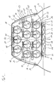
- schematisch vereinfacht eine vergrößert dargestellte Schnittansicht entlang des Schnittverlaufs II-II in
Fig. 1 , - Fig. 3
- schematisch vereinfacht einen vorderen, oberen Bereich eines Unterseeboots mit einem abgesetzt von dem Unterseeboot dargestellten zweiten Bewaffnungsmodul in einem Längsschnitt und
- Fig. 4
- das Bewaffnungsmodul nach
Fig. 3 in einer vergrößerten Schnittansicht entlang der Schnittlinie IV-IV inFig. 3
- Fig. 1
- schematically simplifies a front, upper area of a submarine with an armament module arranged there in a longitudinal section,
- Fig.2
- schematically simplified an enlarged sectional view along the section line II-II in
Fig. 1 . - Fig. 3
- schematically simplifies a front, upper portion of a submarine with a second armament module deposed remotely from the submarine in a longitudinal section and
- Fig. 4
- the armament module
Fig. 3 in an enlarged sectional view along the section line IV-IV inFig. 3
In den
Wie insbesondere
Sowohl das in den
Die Bewaffnungsmodule 10 und 10' weisen jeweils eine Außenverkleidung 26 auf, die mit der Außenhaut 4 des Unterseeboots derart korrespondiert, dass die Außenseite der Außenverkleidung 26 mit der Außenseite der daran angrenzenden Bereiche der Außenhaut 4 fluchtet. Insofern bildet die Außenverkleidung 26 auch einen Teil der Außenhaut 4 des Unterseeboots. Die Oberseite der Außenverkleidung 26 bildet einen Teil des Oberdecks 8. Ein an dem Übergang von der Außenverkleidung 26 des Bewaffnungsmoduls 10 bzw. 10' zu der Außenhaut 4 bestehender Spalt wird mit einem um den Außenrand der Außenverkleidung 26 umlaufenden Profilgummi 28 verschlossen.The
Bei dem in den
Die Waffenrohre 38 dienen vorrangig zum Lagern und Ausbringen von Torpedos. Sie sind druckfest ausgeführt, wobei die von dem Druckkörper 2 abgewandten Auslassöffnungen der Waffenrohre 38 jeweils mit einer Mündungsklappe 42 und die dem Druckkörper 2 zugewandten Öffnungen der Waffenrohre 38 jeweils mit einer Bodenklappe 44 verschlossen sind. Die Mündungsklappen 42 sind jeweils starr mit Außenhautklappen 46 verbunden, die vor den Waffenrohren 38 angeordnet sind und einen Teil der Außenverkleidung 26 des Bewaffnungsmoduls 10 bzw. der Außenhaut 4 bilden.The
Direkt an die Auslassöffnungen angrenzend sind an den Waffenrohren 38 hydraulische Antriebe 48 zum Verschwenken der Mündungsklappen 42 angeordnet. Die Mündungsklappen 42 sind jeweils über einen Mündungsklappenhebel 50 mit einer Antriebswelle 52 des Antriebs 48 bewegungsgekoppelt. Die Mündungsklappe 42 ist mit der Bodenklappe 44 über ein in der Zeichnung aus Übersichtlichkeitsgründen nicht dargestelltes Gestänge bewegungsgekoppelt. Wird eine Mündungsklappe 42 eines Waffenrohrs 38 mittels des Antriebs 48 in eine Öffnungsstellung geschwenkt, wird über das Gestänge auch die Bodenklappe 44 des betreffenden Waffenrohrs 38 in eine Öffnungsstellung geschwenkt, was beim Auslaufen oder beim Ausstoß einer in dem Waffenrohr 38 gelagerten Waffe ein ungehindertes Nachströmen von Wasser ermöglicht.Adjacent to the outlet openings,
Vor dem Öffnen der Mündungsklappe 42 und der Bodenklappe 44 ist es erforderlich, das betreffende Waffenrohr 38 zu entlüften und zu bewässern. Hierzu sind Belüftungsventile 54 sowie Be- und Entwässerungsventile 56 vorgesehen, die an den einzelnen Waffenrohren 38 jeweils an der äußeren Mantelfläche angeordnet sind.Before opening the
Zum Betrieb und zur Steuerung der Bewaffnungsmodule 10 und 10' sind an der Oberseite des Druckkörpers 2 mehrere Hydraulikspeicher 58 und eine elektrisch/hydraulische Modulsteuerung 60 angeordnet. Sowohl die Hydraulikspeicher 58 als auch die Modulsteuerung 60 sind in einem schockelastisch auf Dämpfungselementen 62 gelagerten Rahmengestell 64 zusammengefasst. Zur Versorgung und Ansteuerung der Belüftungsventile 54, der Be- und Entwässerungsventile 56 sowie der Antriebe 48 sind hydraulische und elektrische Leitungen 66 entlang der Waffenrohre 38 geführt. Die Verbindung der hydraulischen Leitungen mit den Hydraulikspeichern 58 erfolgt über Schnellkupplungen 68 und dazwischen geschaltete Schlauchkompensatoren 70. Zur Verbindung der elektrischen Leitungen des Bewaffnungsmoduls 10 mit der bootsseitig angeordneten Modulsteuerung 60 sind druckdichte Steckverbindungen 72 vorgesehen. Die hydraulische und elektrische Verbindung der Druckspeicher 58 sowie der Modulsteuerung 60 mit dem Druckkörperinneren erfolgt über Druckkörperdurchführungen 74 und 76. Eine weitere Druckkörperdurchführung 78 dient zur Führung von Datenübertragungskabeln in das Innere des Druckkörpers 2.For the operation and control of the
Das in den
- 2 -2 -
- Druckkörperpressure vessels
- 4 -4 -
- Außenhautshell
- 6 -6 -
- Zwischenraumgap
- 8 -8th -
- Oberdeckupper deck
- 10, 10' -10, 10 '-
- Bewaffnungsmodularmament module
- 12 -12 -
- TragwerkStructure
- 14 -14 -
- Dämpfungselementdamping element
- 16 -16 -
- Vertiefungdeepening
- 18 -18 -
- Lagerungsfundamentstorage foundation
- 20 -20 -
- Führungszapfenspigot
- 22 -22 -
- Verriegelungselementlocking element
- 24 -24 -
- Verriegelungselementlocking element
- 26 -26 -
- AußenverkleidungSiding
- 28 -28 -
- Profilgummirubber
- 30 -30 -
- Stützschottsupport Schott
- 32 -32 -
- Stützschottsupport Schott
- 34 -34 -
- Stützschottsupport Schott
- 36 -36 -
- Halteeinrichtungholder
- 38 -38 -
- Waffenrohrbarrel
- 40 -40 -
- Durchbrechungperforation
- 42 -42 -
- Mündungsklappemouth flap
- 44 -44 -
- Bodenklappebottom flap
- 46 -46 -
- AußenhautklappeSkin flap
- 48 -48 -
- Antriebdrive
- 50 -50 -
- MündungsklappenhebelMouth flap lever
- 52 -52 -
- Antriebswelledrive shaft
- 54 -54 -
- Belüftungsventilvent valve
- 56 -56 -
- Be- und EntwässerungsventilLoading and drainage valve
- 58 -58 -
- Hydraulikspeicherhydraulic accumulator
- 60 -60 -
- Modulsteuerungmodule control
- 62 -62 -
- Dämpfungselementdamping element
- 64 -64 -
- Rahmengestellframe
- 66 -66 -
- Hydraulische und elektrische LeitungenHydraulic and electrical cables
- 68 -68 -
- Schnellkupplungquick coupling
- 70 -70 -
- SchlauchkompensatorTubular
- 72 -72 -
- Steckverbindungconnector
- 74 -74 -
- DruckkörperdurchführungPressure vessels implementing
- 76 -76 -
- DruckkörperdurchführungPressure vessels implementing
- 78 -78 -
- DruckkörperdurchführungPressure vessels implementing
- 80 -80 -
- Stützschottsupport Schott
- 82 -82 -
- Stützschottsupport Schott
- 84 -84 -
- Stützschottsupport Schott
- 86 -86 -
- Waffenrohrbarrel
- A -A -
- Längsachselongitudinal axis
Claims (10)
Priority Applications (1)
| Application Number | Priority Date | Filing Date | Title |
|---|---|---|---|
| PL11184525T PL2441663T3 (en) | 2010-10-12 | 2011-10-10 | Submarine |
Applications Claiming Priority (1)
| Application Number | Priority Date | Filing Date | Title |
|---|---|---|---|
| DE102010048222A DE102010048222A1 (en) | 2010-10-12 | 2010-10-12 | submarine |
Publications (2)
| Publication Number | Publication Date |
|---|---|
| EP2441663A1 true EP2441663A1 (en) | 2012-04-18 |
| EP2441663B1 EP2441663B1 (en) | 2014-04-16 |
Family
ID=44759568
Family Applications (1)
| Application Number | Title | Priority Date | Filing Date |
|---|---|---|---|
| EP11184525.1A Active EP2441663B1 (en) | 2010-10-12 | 2011-10-10 | Submarine |
Country Status (5)
| Country | Link |
|---|---|
| EP (1) | EP2441663B1 (en) |
| KR (1) | KR101288983B1 (en) |
| DE (1) | DE102010048222A1 (en) |
| ES (1) | ES2478282T3 (en) |
| PL (1) | PL2441663T3 (en) |
Cited By (2)
| Publication number | Priority date | Publication date | Assignee | Title |
|---|---|---|---|---|
| EP2736800B1 (en) | 2011-07-28 | 2015-07-15 | Dcns | Underwater vehicle comprising at least one loader of at least two munitions, the loader being removable and extractible through an opening in a thin hole of this vehicle |
| WO2018197626A1 (en) | 2017-04-28 | 2018-11-01 | Naval Group | Underwater vehicle |
Families Citing this family (3)
| Publication number | Priority date | Publication date | Assignee | Title |
|---|---|---|---|---|
| DE102015221096B4 (en) * | 2015-10-28 | 2018-07-19 | Thyssenkrupp Ag | Underwater vehicle with an underwater storage device |
| KR102434532B1 (en) * | 2016-01-13 | 2022-08-18 | 대우조선해양 주식회사 | Apparatus for launching weapon of underwater moving body |
| DE102018222490A1 (en) * | 2018-12-20 | 2020-06-25 | Atlas Elektronik Gmbh | Device and method for starting an underwater running body from a watercraft |
Citations (5)
| Publication number | Priority date | Publication date | Assignee | Title |
|---|---|---|---|---|
| DE2416801A1 (en) * | 1974-04-06 | 1979-01-11 | Gemmecke Kurt Ing Grad | Torpedo launching system - has torpedo tubes in housings which are transported by submarine and deposited on sea bed |
| DE2454738A1 (en) | 1974-11-19 | 1979-05-17 | Mak Maschinenbau Gmbh | External launcher for torpedo - has light housing filled with preserving fluid and fitted with pressure control membrane |
| DE3723817A1 (en) * | 1987-07-18 | 1989-01-26 | Rudolf Dr Wieser | Submarine |
| US5363791A (en) * | 1993-05-11 | 1994-11-15 | Newport News Shipbuilding And Dry Dock Company | Weapons launch system |
| US5964175A (en) * | 1997-09-25 | 1999-10-12 | The United States Of America As Represented By The Secretary Of The Navy | Conformal detachable platform array |
-
2010
- 2010-10-12 DE DE102010048222A patent/DE102010048222A1/en not_active Withdrawn
-
2011
- 2011-09-26 KR KR1020110096940A patent/KR101288983B1/en active Active
- 2011-10-10 PL PL11184525T patent/PL2441663T3/en unknown
- 2011-10-10 EP EP11184525.1A patent/EP2441663B1/en active Active
- 2011-10-10 ES ES11184525.1T patent/ES2478282T3/en active Active
Patent Citations (5)
| Publication number | Priority date | Publication date | Assignee | Title |
|---|---|---|---|---|
| DE2416801A1 (en) * | 1974-04-06 | 1979-01-11 | Gemmecke Kurt Ing Grad | Torpedo launching system - has torpedo tubes in housings which are transported by submarine and deposited on sea bed |
| DE2454738A1 (en) | 1974-11-19 | 1979-05-17 | Mak Maschinenbau Gmbh | External launcher for torpedo - has light housing filled with preserving fluid and fitted with pressure control membrane |
| DE3723817A1 (en) * | 1987-07-18 | 1989-01-26 | Rudolf Dr Wieser | Submarine |
| US5363791A (en) * | 1993-05-11 | 1994-11-15 | Newport News Shipbuilding And Dry Dock Company | Weapons launch system |
| US5964175A (en) * | 1997-09-25 | 1999-10-12 | The United States Of America As Represented By The Secretary Of The Navy | Conformal detachable platform array |
Cited By (2)
| Publication number | Priority date | Publication date | Assignee | Title |
|---|---|---|---|---|
| EP2736800B1 (en) | 2011-07-28 | 2015-07-15 | Dcns | Underwater vehicle comprising at least one loader of at least two munitions, the loader being removable and extractible through an opening in a thin hole of this vehicle |
| WO2018197626A1 (en) | 2017-04-28 | 2018-11-01 | Naval Group | Underwater vehicle |
Also Published As
| Publication number | Publication date |
|---|---|
| KR101288983B1 (en) | 2013-07-22 |
| DE102010048222A1 (en) | 2012-04-12 |
| ES2478282T3 (en) | 2014-07-21 |
| KR20120037875A (en) | 2012-04-20 |
| EP2441663B1 (en) | 2014-04-16 |
| PL2441663T3 (en) | 2014-09-30 |
Similar Documents
| Publication | Publication Date | Title |
|---|---|---|
| EP2441663B1 (en) | Submarine | |
| EP2261112B1 (en) | Submarine with device carrier | |
| DE69504064T2 (en) | UNDERWATER WEAPON HANDLING AND LAUNCHING SYSTEM | |
| EP2568250B1 (en) | On the seabed deployable device for storing and supplying at least one weapon | |
| DE102011112425A1 (en) | Installation vehicle for a tidal power plant and method for its operation | |
| DE102011087889B4 (en) | submarine | |
| EP3623276B1 (en) | Submarine with cover opening drive | |
| EP1167181B1 (en) | Container for storing and launching underwater objects | |
| EP2532577B1 (en) | Submarine | |
| EP3169966B1 (en) | Weapon transport system for a submarine | |
| EP2206644B1 (en) | Submarine | |
| DE102014111488A1 (en) | Starting device and vehicle | |
| DE2029516C1 (en) | Torpedo ring magazine for underwater vehicles | |
| DE2454738C2 (en) | Tubular container for floating and diving bodies | |
| DE2416801A1 (en) | Torpedo launching system - has torpedo tubes in housings which are transported by submarine and deposited on sea bed | |
| DE102019203073B4 (en) | Submarine with a lid with a vent | |
| DE69805746T2 (en) | CONTAINER FOR STORING AND LOCKING A TORPEDO | |
| EP1493657B1 (en) | Submarine | |
| EP2345578B1 (en) | Submarine | |
| EP1783047B1 (en) | Submarine with a tow-line | |
| WO2018219774A1 (en) | Underwater transport container for combat divers | |
| EP3204290B1 (en) | Submarine | |
| DE10335524B3 (en) | Storage and discharge container used in a submarines comprises a liquid-tight flexible sleeve surrounding a discharge device, underwater swimming bodies and upper guide rails | |
| DE102016115450A1 (en) | Thrusters | |
| DE102008057123B4 (en) | Large caliber artillery on compact warships and speedboats |
Legal Events
| Date | Code | Title | Description |
|---|---|---|---|
| PUAI | Public reference made under article 153(3) epc to a published international application that has entered the european phase |
Free format text: ORIGINAL CODE: 0009012 |
|
| AK | Designated contracting states |
Kind code of ref document: A1 Designated state(s): AL AT BE BG CH CY CZ DE DK EE ES FI FR GB GR HR HU IE IS IT LI LT LU LV MC MK MT NL NO PL PT RO RS SE SI SK SM TR |
|
| AX | Request for extension of the european patent |
Extension state: BA ME |
|
| 17P | Request for examination filed |
Effective date: 20121015 |
|
| RAP1 | Party data changed (applicant data changed or rights of an application transferred) |
Owner name: THYSSENKRUPP MARINE SYSTEMS GMBH |
|
| GRAP | Despatch of communication of intention to grant a patent |
Free format text: ORIGINAL CODE: EPIDOSNIGR1 |
|
| INTG | Intention to grant announced |
Effective date: 20131122 |
|
| GRAS | Grant fee paid |
Free format text: ORIGINAL CODE: EPIDOSNIGR3 |
|
| GRAA | (expected) grant |
Free format text: ORIGINAL CODE: 0009210 |
|
| AK | Designated contracting states |
Kind code of ref document: B1 Designated state(s): AL AT BE BG CH CY CZ DE DK EE ES FI FR GB GR HR HU IE IS IT LI LT LU LV MC MK MT NL NO PL PT RO RS SE SI SK SM TR |
|
| REG | Reference to a national code |
Ref country code: GB Ref legal event code: FG4D Free format text: NOT ENGLISH |
|
| REG | Reference to a national code |
Ref country code: CH Ref legal event code: EP |
|
| REG | Reference to a national code |
Ref country code: AT Ref legal event code: REF Ref document number: 662344 Country of ref document: AT Kind code of ref document: T Effective date: 20140515 |
|
| REG | Reference to a national code |
Ref country code: IE Ref legal event code: FG4D Free format text: LANGUAGE OF EP DOCUMENT: GERMAN |
|
| REG | Reference to a national code |
Ref country code: DE Ref legal event code: R096 Ref document number: 502011002721 Country of ref document: DE Effective date: 20140605 |
|
| REG | Reference to a national code |
Ref country code: NL Ref legal event code: T3 |
|
| REG | Reference to a national code |
Ref country code: ES Ref legal event code: FG2A Ref document number: 2478282 Country of ref document: ES Kind code of ref document: T3 Effective date: 20140721 |
|
| REG | Reference to a national code |
Ref country code: SE Ref legal event code: TRGR |
|
| REG | Reference to a national code |
Ref country code: NO Ref legal event code: T2 Effective date: 20140416 |
|
| REG | Reference to a national code |
Ref country code: LT Ref legal event code: MG4D |
|
| REG | Reference to a national code |
Ref country code: PL Ref legal event code: T3 |
|
| PG25 | Lapsed in a contracting state [announced via postgrant information from national office to epo] |
Ref country code: IS Free format text: LAPSE BECAUSE OF FAILURE TO SUBMIT A TRANSLATION OF THE DESCRIPTION OR TO PAY THE FEE WITHIN THE PRESCRIBED TIME-LIMIT Effective date: 20140816 Ref country code: FI Free format text: LAPSE BECAUSE OF FAILURE TO SUBMIT A TRANSLATION OF THE DESCRIPTION OR TO PAY THE FEE WITHIN THE PRESCRIBED TIME-LIMIT Effective date: 20140416 Ref country code: GR Free format text: LAPSE BECAUSE OF FAILURE TO SUBMIT A TRANSLATION OF THE DESCRIPTION OR TO PAY THE FEE WITHIN THE PRESCRIBED TIME-LIMIT Effective date: 20140717 Ref country code: LT Free format text: LAPSE BECAUSE OF FAILURE TO SUBMIT A TRANSLATION OF THE DESCRIPTION OR TO PAY THE FEE WITHIN THE PRESCRIBED TIME-LIMIT Effective date: 20140416 Ref country code: BG Free format text: LAPSE BECAUSE OF FAILURE TO SUBMIT A TRANSLATION OF THE DESCRIPTION OR TO PAY THE FEE WITHIN THE PRESCRIBED TIME-LIMIT Effective date: 20140716 Ref country code: CY Free format text: LAPSE BECAUSE OF FAILURE TO SUBMIT A TRANSLATION OF THE DESCRIPTION OR TO PAY THE FEE WITHIN THE PRESCRIBED TIME-LIMIT Effective date: 20140416 |
|
| PG25 | Lapsed in a contracting state [announced via postgrant information from national office to epo] |
Ref country code: RS Free format text: LAPSE BECAUSE OF FAILURE TO SUBMIT A TRANSLATION OF THE DESCRIPTION OR TO PAY THE FEE WITHIN THE PRESCRIBED TIME-LIMIT Effective date: 20140416 Ref country code: LV Free format text: LAPSE BECAUSE OF FAILURE TO SUBMIT A TRANSLATION OF THE DESCRIPTION OR TO PAY THE FEE WITHIN THE PRESCRIBED TIME-LIMIT Effective date: 20140416 Ref country code: HR Free format text: LAPSE BECAUSE OF FAILURE TO SUBMIT A TRANSLATION OF THE DESCRIPTION OR TO PAY THE FEE WITHIN THE PRESCRIBED TIME-LIMIT Effective date: 20140416 |
|
| PG25 | Lapsed in a contracting state [announced via postgrant information from national office to epo] |
Ref country code: PT Free format text: LAPSE BECAUSE OF FAILURE TO SUBMIT A TRANSLATION OF THE DESCRIPTION OR TO PAY THE FEE WITHIN THE PRESCRIBED TIME-LIMIT Effective date: 20140818 |
|
| REG | Reference to a national code |
Ref country code: DE Ref legal event code: R097 Ref document number: 502011002721 Country of ref document: DE |
|
| PG25 | Lapsed in a contracting state [announced via postgrant information from national office to epo] |
Ref country code: SK Free format text: LAPSE BECAUSE OF FAILURE TO SUBMIT A TRANSLATION OF THE DESCRIPTION OR TO PAY THE FEE WITHIN THE PRESCRIBED TIME-LIMIT Effective date: 20140416 Ref country code: CZ Free format text: LAPSE BECAUSE OF FAILURE TO SUBMIT A TRANSLATION OF THE DESCRIPTION OR TO PAY THE FEE WITHIN THE PRESCRIBED TIME-LIMIT Effective date: 20140416 Ref country code: EE Free format text: LAPSE BECAUSE OF FAILURE TO SUBMIT A TRANSLATION OF THE DESCRIPTION OR TO PAY THE FEE WITHIN THE PRESCRIBED TIME-LIMIT Effective date: 20140416 Ref country code: DK Free format text: LAPSE BECAUSE OF FAILURE TO SUBMIT A TRANSLATION OF THE DESCRIPTION OR TO PAY THE FEE WITHIN THE PRESCRIBED TIME-LIMIT Effective date: 20140416 Ref country code: RO Free format text: LAPSE BECAUSE OF FAILURE TO SUBMIT A TRANSLATION OF THE DESCRIPTION OR TO PAY THE FEE WITHIN THE PRESCRIBED TIME-LIMIT Effective date: 20140416 |
|
| REG | Reference to a national code |
Ref country code: DE Ref legal event code: R084 Ref document number: 502011002721 Country of ref document: DE |
|
| PLBE | No opposition filed within time limit |
Free format text: ORIGINAL CODE: 0009261 |
|
| STAA | Information on the status of an ep patent application or granted ep patent |
Free format text: STATUS: NO OPPOSITION FILED WITHIN TIME LIMIT |
|
| 26N | No opposition filed |
Effective date: 20150119 |
|
| REG | Reference to a national code |
Ref country code: DE Ref legal event code: R084 Ref document number: 502011002721 Country of ref document: DE Effective date: 20150206 |
|
| REG | Reference to a national code |
Ref country code: DE Ref legal event code: R097 Ref document number: 502011002721 Country of ref document: DE Effective date: 20150119 |
|
| PG25 | Lapsed in a contracting state [announced via postgrant information from national office to epo] |
Ref country code: MC Free format text: LAPSE BECAUSE OF FAILURE TO SUBMIT A TRANSLATION OF THE DESCRIPTION OR TO PAY THE FEE WITHIN THE PRESCRIBED TIME-LIMIT Effective date: 20140416 Ref country code: LU Free format text: LAPSE BECAUSE OF FAILURE TO SUBMIT A TRANSLATION OF THE DESCRIPTION OR TO PAY THE FEE WITHIN THE PRESCRIBED TIME-LIMIT Effective date: 20141010 |
|
| REG | Reference to a national code |
Ref country code: CH Ref legal event code: PL |
|
| PG25 | Lapsed in a contracting state [announced via postgrant information from national office to epo] |
Ref country code: BE Free format text: LAPSE BECAUSE OF NON-PAYMENT OF DUE FEES Effective date: 20141031 |
|
| REG | Reference to a national code |
Ref country code: IE Ref legal event code: MM4A |
|
| PG25 | Lapsed in a contracting state [announced via postgrant information from national office to epo] |
Ref country code: SI Free format text: LAPSE BECAUSE OF FAILURE TO SUBMIT A TRANSLATION OF THE DESCRIPTION OR TO PAY THE FEE WITHIN THE PRESCRIBED TIME-LIMIT Effective date: 20140416 Ref country code: LI Free format text: LAPSE BECAUSE OF NON-PAYMENT OF DUE FEES Effective date: 20141031 Ref country code: CH Free format text: LAPSE BECAUSE OF NON-PAYMENT OF DUE FEES Effective date: 20141031 |
|
| REG | Reference to a national code |
Ref country code: FR Ref legal event code: PLFP Year of fee payment: 5 |
|
| PG25 | Lapsed in a contracting state [announced via postgrant information from national office to epo] |
Ref country code: IE Free format text: LAPSE BECAUSE OF NON-PAYMENT OF DUE FEES Effective date: 20141010 |
|
| PG25 | Lapsed in a contracting state [announced via postgrant information from national office to epo] |
Ref country code: SM Free format text: LAPSE BECAUSE OF FAILURE TO SUBMIT A TRANSLATION OF THE DESCRIPTION OR TO PAY THE FEE WITHIN THE PRESCRIBED TIME-LIMIT Effective date: 20140416 |
|
| PG25 | Lapsed in a contracting state [announced via postgrant information from national office to epo] |
Ref country code: MT Free format text: LAPSE BECAUSE OF FAILURE TO SUBMIT A TRANSLATION OF THE DESCRIPTION OR TO PAY THE FEE WITHIN THE PRESCRIBED TIME-LIMIT Effective date: 20140416 Ref country code: HU Free format text: LAPSE BECAUSE OF FAILURE TO SUBMIT A TRANSLATION OF THE DESCRIPTION OR TO PAY THE FEE WITHIN THE PRESCRIBED TIME-LIMIT; INVALID AB INITIO Effective date: 20111010 |
|
| REG | Reference to a national code |
Ref country code: FR Ref legal event code: PLFP Year of fee payment: 6 |
|
| REG | Reference to a national code |
Ref country code: FR Ref legal event code: PLFP Year of fee payment: 7 |
|
| REG | Reference to a national code |
Ref country code: AT Ref legal event code: MM01 Ref document number: 662344 Country of ref document: AT Kind code of ref document: T Effective date: 20161010 |
|
| PG25 | Lapsed in a contracting state [announced via postgrant information from national office to epo] |
Ref country code: AT Free format text: LAPSE BECAUSE OF NON-PAYMENT OF DUE FEES Effective date: 20161010 |
|
| PG25 | Lapsed in a contracting state [announced via postgrant information from national office to epo] |
Ref country code: MK Free format text: LAPSE BECAUSE OF FAILURE TO SUBMIT A TRANSLATION OF THE DESCRIPTION OR TO PAY THE FEE WITHIN THE PRESCRIBED TIME-LIMIT Effective date: 20140416 |
|
| REG | Reference to a national code |
Ref country code: FR Ref legal event code: PLFP Year of fee payment: 8 |
|
| PG25 | Lapsed in a contracting state [announced via postgrant information from national office to epo] |
Ref country code: AL Free format text: LAPSE BECAUSE OF FAILURE TO SUBMIT A TRANSLATION OF THE DESCRIPTION OR TO PAY THE FEE WITHIN THE PRESCRIBED TIME-LIMIT Effective date: 20140416 |
|
| REG | Reference to a national code |
Ref country code: DE Ref legal event code: R081 Ref document number: 502011002721 Country of ref document: DE Owner name: THYSSENKRUPP MARINE SYSTEMS GMBH, DE Free format text: FORMER OWNER: THYSSENKRUPP MARINE SYSTEMS GMBH, 24143 KIEL, DE |
|
| P01 | Opt-out of the competence of the unified patent court (upc) registered |
Effective date: 20230530 |
|
| REG | Reference to a national code |
Ref country code: DE Ref legal event code: R081 Ref document number: 502011002721 Country of ref document: DE Owner name: TKMS GMBH, DE Free format text: FORMER OWNER: THYSSENKRUPP MARINE SYSTEMS GMBH, 24143 KIEL, DE |
|
| PGFP | Annual fee paid to national office [announced via postgrant information from national office to epo] |
Ref country code: NL Payment date: 20251021 Year of fee payment: 15 |
|
| PGFP | Annual fee paid to national office [announced via postgrant information from national office to epo] |
Ref country code: DE Payment date: 20251021 Year of fee payment: 15 |
|
| PGFP | Annual fee paid to national office [announced via postgrant information from national office to epo] |
Ref country code: GB Payment date: 20251022 Year of fee payment: 15 |
|
| PGFP | Annual fee paid to national office [announced via postgrant information from national office to epo] |
Ref country code: NO Payment date: 20251024 Year of fee payment: 15 |
|
| PGFP | Annual fee paid to national office [announced via postgrant information from national office to epo] |
Ref country code: IT Payment date: 20251024 Year of fee payment: 15 |
|
| PGFP | Annual fee paid to national office [announced via postgrant information from national office to epo] |
Ref country code: FR Payment date: 20251030 Year of fee payment: 15 |
|
| PGFP | Annual fee paid to national office [announced via postgrant information from national office to epo] |
Ref country code: TR Payment date: 20251006 Year of fee payment: 15 |
|
| PGFP | Annual fee paid to national office [announced via postgrant information from national office to epo] |
Ref country code: SE Payment date: 20251021 Year of fee payment: 15 |
|
| PGFP | Annual fee paid to national office [announced via postgrant information from national office to epo] |
Ref country code: PL Payment date: 20251006 Year of fee payment: 15 |
|
| PGFP | Annual fee paid to national office [announced via postgrant information from national office to epo] |
Ref country code: ES Payment date: 20251210 Year of fee payment: 15 |