EP2441653A1 - Floor assembly for a number of construction variants of a bodywork of a passenger vehicle, in particular with rear-wheel drive engine - Google Patents
Floor assembly for a number of construction variants of a bodywork of a passenger vehicle, in particular with rear-wheel drive engine Download PDFInfo
- Publication number
- EP2441653A1 EP2441653A1 EP11008156A EP11008156A EP2441653A1 EP 2441653 A1 EP2441653 A1 EP 2441653A1 EP 11008156 A EP11008156 A EP 11008156A EP 11008156 A EP11008156 A EP 11008156A EP 2441653 A1 EP2441653 A1 EP 2441653A1
- Authority
- EP
- European Patent Office
- Prior art keywords
- variant
- module
- floor
- main floor
- specific
- Prior art date
- Legal status (The legal status is an assumption and is not a legal conclusion. Google has not performed a legal analysis and makes no representation as to the accuracy of the status listed.)
- Granted
Links
- 238000010276 construction Methods 0.000 title claims description 28
- 238000004519 manufacturing process Methods 0.000 claims abstract description 7
- 238000000034 method Methods 0.000 claims abstract description 7
- 238000005452 bending Methods 0.000 claims description 6
- 239000002243 precursor Substances 0.000 claims description 5
- 238000009966 trimming Methods 0.000 claims description 5
- 238000013461 design Methods 0.000 abstract description 9
- 230000000712 assembly Effects 0.000 abstract 1
- 238000000429 assembly Methods 0.000 abstract 1
- 238000010521 absorption reaction Methods 0.000 description 3
- 230000006978 adaptation Effects 0.000 description 3
- 239000002184 metal Substances 0.000 description 2
- 239000004918 carbon fiber reinforced polymer Substances 0.000 description 1
- 230000001419 dependent effect Effects 0.000 description 1
- 238000011161 development Methods 0.000 description 1
- 230000018109 developmental process Effects 0.000 description 1
- 238000004146 energy storage Methods 0.000 description 1
- 230000002349 favourable effect Effects 0.000 description 1
- 239000007788 liquid Substances 0.000 description 1
- 239000000463 material Substances 0.000 description 1
- 229910001092 metal group alloy Inorganic materials 0.000 description 1
- 238000012986 modification Methods 0.000 description 1
- 230000004048 modification Effects 0.000 description 1
- 239000004033 plastic Substances 0.000 description 1
- 230000002035 prolonged effect Effects 0.000 description 1
- 239000002689 soil Substances 0.000 description 1
- 210000002023 somite Anatomy 0.000 description 1
- 238000012546 transfer Methods 0.000 description 1
- 230000007704 transition Effects 0.000 description 1
Images


Classifications
-
- B—PERFORMING OPERATIONS; TRANSPORTING
- B62—LAND VEHICLES FOR TRAVELLING OTHERWISE THAN ON RAILS
- B62D—MOTOR VEHICLES; TRAILERS
- B62D21/00—Understructures, i.e. chassis frame on which a vehicle body may be mounted
- B62D21/14—Understructures, i.e. chassis frame on which a vehicle body may be mounted of adjustable length or width
-
- B—PERFORMING OPERATIONS; TRANSPORTING
- B62—LAND VEHICLES FOR TRAVELLING OTHERWISE THAN ON RAILS
- B62D—MOTOR VEHICLES; TRAILERS
- B62D25/00—Superstructure or monocoque structure sub-units; Parts or details thereof not otherwise provided for
- B62D25/20—Floors or bottom sub-units
- B62D25/2009—Floors or bottom sub-units in connection with other superstructure subunits
-
- B—PERFORMING OPERATIONS; TRANSPORTING
- B62—LAND VEHICLES FOR TRAVELLING OTHERWISE THAN ON RAILS
- B62D—MOTOR VEHICLES; TRAILERS
- B62D63/00—Motor vehicles or trailers not otherwise provided for
- B62D63/02—Motor vehicles
- B62D63/025—Modular vehicles
Definitions
- the invention relates to a floor assembly for a plurality of construction variants of a body of a passenger car. Furthermore, the invention relates to a modular system for such a floor assembly. Finally, the invention relates to a method for producing such a floor assembly.
- Object of the present invention is therefore to provide a floor assembly of a passenger car, especially with rear-wheel drive unit, a modular system for such a floor assembly and a method for producing such a floor group, by means of which can significantly reduce the cost of a respective construction variant of the body of the passenger car ,
- the floor assembly of the invention according to claim 1 is characterized in that it is a variant-overlapping front module and a multi-variant rear module for the majority of construction variants of the body of the passenger car comprises, with the front module and rear module are connected to each other via a bottom assembly, which is formed as a function of the respective construction variants of the body of the passenger car.
- the front module and the rear module across the plurality of construction variants of the body at least substantially identical form, whereas the respective floor assembly that connect the front module and the rear module with each other, depending variable depending on the particular construction variant, for which the floor assembly is to be created.
- the adaptation of the floor assembly is thus essentially by the variation of the floor assembly, which can be varied depending on the particular construction variant in their dimensions or in terms of other properties such as the choice of material or the like.
- the floor assembly extends at least substantially in the region of the main floor of the respective construction variant, since in this area corresponding adjustments are made particularly favorable.
- the at least one interface between the front module and the respective floor arrangement and the at least one interface between the rear module and the respective floor arrangement is always the same or at least substantially identical regardless of the respective floor arrangement.
- the floor assembly can be replaced and connected to the stem and the rear module in a defined manner, which is particularly advantageous on the production side.
- a further advantageous embodiment provides that the floor arrangement has a variant-specific first main floor module and that on the outside of the variant-specific first main floor module respective variant-specific lateral side rail elements are attached.
- a short module can be used to create, for example, a two- or three-seater vehicle with a short main floor.
- the entire main floor is formed by the first main floor module.
- This allows a particularly rigid and stable design of the floor assembly.
- Alternative length variants of the floor group can be created by the use of different main floor modules.
- a common precursor component is expediently provided, from which the desired length variants of the main floor module are produced by different trimming.
- a second main floor module which is attached to the first main floor module.
- a floor assembly for a vehicle with four or five seats or more can be created.
- respective variant-specific lateral side member members are attached, which are adapted to the respective length of the two main floor modules or the main floor as a whole.
- longitudinal beam elements can be used which differ in their width depending on the respective construction variant.
- different vehicle widths can be easily adapted by appropriate design of the side member elements in their width.
- a respective at least partially variant-specific bending beam module is attached to the variant-overlapping front module or the multi-variant rear module.
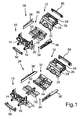
- Fig. 1 are shown in respective perspective view two exploded views of respective floor groups for a corresponding body of a passenger car.
- the floor group shown above is also in the Fig. 2a and 2b and will be explained in more detail below. Also in the following is the in Fig. 1 Bottom group shown below, which also in the Fig. 3a and 3b is apparent.
- the two floor groups are part of a modular system with which a plurality of different floor groups for different construction variants of the body of the passenger car can be produced.
- the bottom group shown above is present for a two-seat or three-seater body of a passenger car, for example a coupe or the like.
- the floor group shown below is primarily designed for a prolonged body variant (eg with four or more seats or a van version).
- Both floor groups each include a variant-overlapping front module 10 and a multi-variant rear module 12, which are formed at least substantially independent of the respective construction variant of the body.
- the front module 10 comprises, as essential elements, an end wall 14, respective side members 16, respective side wall elements 18 for corresponding door pillars, and a main floor area 20.
- the present frontal module 10 is composed of a plurality of sheet metal components or sheet metal shell elements. Other designs are also conceivable.
- the rear module 12 essentially comprises a rear wall 22, respective cross member elements 24 and respective side wall elements 26.
- the front module 10 and the rear module 12 via a respective bottom assembly 28, 28 'connected to each other, which is formed depending on the respective construction variant of the body.
- the floor assembly 28 includes the in Fig. 1 The body shown above only a first main floor module 30, which is attached to the front of the front module 10 and the rear of the rear module 12 on the front.
- the longer floor group which in Fig. 1 below, however, includes a floor assembly 28 'that includes a second main floor module 32 in addition to the first main floor module 30.
- This main floor module 32 is attached to the rear side of the first main floor module 30 and connects it to the rear module 12.
- the second main floor module 32 forms an extension of the floor assembly.
- a corresponding main floor 34 is formed by only the first main floor module 30, a main floor 34 'of the assembly according to Fig. 1 at the bottom formed by the two main floor modules 30, 32.
- FIG. 5 An alternative to forming length variations of the main floor 34 through the use of multiple main floor modules 30, 32 is in FIG Fig. 5 shown.
- the main floor 34 is in this case formed integrally in all length variants by a single main floor module 30 ', 30 "It is particularly expedient to produce the differently long main floor modules 30', 30" by different trimming a common precursor component in order to save production costs.
- the one-piece main floor module 30 ' corresponds to FIG Fig. 5 the in FIG. 1
- the main floor module 30 "corresponds to areas 20, 52 and 54, respectively FIG. 1 ,
- FIG. 1 recognizable that by varying the respective floor assembly 28, 28 ', the floor assembly is to vary in their length. As a result, a maximum share of identical parts is realized and enables a more cost-effective realization of different wheelbase lengths.
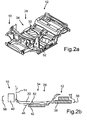
- Fig. 2a is the in Fig. 1 shown above assembly again in a perspective view completely.
- Fig. 2b a sectional view along a vehicle in the vertical direction or in the vehicle longitudinal direction extending central longitudinal section plane shown.
- a drive unit 38 which may also be designed in a modular manner, for example, is arranged in the region of the rear module 12.
- a compact body and module module is created by the rear module 12.
- further units or the like can be provided.
- an aggregate 40 can be seen, but its size is designed such that it is not block-forming.
- the free deformation length is not limited in the area of the stem, which is particularly important for small vehicles of great importance.
- a power module 42 is arranged in the present case, which may for example comprise a corresponding tank or corresponding batteries.
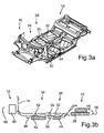
- Fig. 3a and 3b is - analogous to the Fig. 2a and 2b - in the Fig. 1 shown below assembly.
- a single power module which is designed to be large accordingly.
- connection points between the front module 10, the rear module 12 and the respective main floor modules 30, 32 as well as possibly to the side members 36, 36 ' are ideally designed so that they both for the small assembly as well as the large assembly according to Fig. 1 can be used.
- the joints at the connection points are ideally aligned with the vehicle network and, for example, oriented horizontally or vertically, whereby body tolerances for the different wheelbases are easily adjustable.
- cross member 46, 48, 50 are provided below the main floor 34, 34 'respective cross member 46, 48, 50 .
- the cross member 46 is assigned to the front main floor module 30 and thus both in the assembly according to Fig. 2b as with those according to Fig. 3b available.
- the cross member 50 is only according to the longer assembly Fig. 3b present, since this is arranged below the assembly extending second main floor module 32.
- the cross members 46, 48, 50 serve in particular to protect the energy modules 42 and 44 against lateral deformation. In this case, support the cross member 46, 48, 50 respective side rail members 36 and 36 'from.
- a further protection results from a seat cross member or seat consoles 54 of the front, first main floor module 30 and / or a seat cross member or seat consoles 54 of the second main floor module 32. These are each placed from above on the main floor modules 30 and 32 respectively.
- the entire respective floor assembly is generally designed for passenger cars so that multiple generations of vehicle and body variants can be generated.
- the bottom group or individual modules can be created both from a metal alloy or corresponding sheets as well as plastic, such as CFRP. Hybrid variants are also conceivable.
- strut arrangement in the area of the floor arrangement 28, 28 'a strut arrangement can be provided, which increases the rigidity when the assembly is used for a convertible or a roadster with an open roof.
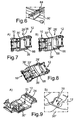
- FIG. 4a and 4b in each case a perspective view of a rear or front Biegelinimoduls 56, 58 shown.
- the front, in Fig. 4a shown bending support module 58 includes two energy absorption elements 60, which may vary in length and / or design depending on the construction variant of the assembly.
- rear bending beam module 56 wherein this additionally comprises a carrier element 62, which may be attached depending on the construction variant of the module or not.
- variable lengths of the energy absorption elements 60 or by the variation of the respective Biegelinimoduls 56 and 58 a flexible adaptation to all functional requirements in terms of vehicle mass, legal and market requirements or the like.
- the variation of the respective Biegelinimoduls 56, 58 the correspondingly desired overhang length Different styling geometries of each passenger car to be adjusted.
- a central, central load path is implemented despite a modular design and different wheelbase lengths by means of a closed profile.
- the usual tunnel 64 is placed in the body interior on a continuous floor 30 ', as in Fig. 6 shown.
- the soil structure is raised in the region of the energy store 66.
- An identical position for most diverse energy storage 66 (liquid / gas tank or electric battery or the like.) Can be implemented in the platform regardless of a short or long vehicle.
- a decisive advantage is that thus the rear drive unit in general or the rear floor 12 in particular can be performed maximally blocked. This is for two different vehicle variants in the Fig. 7a and b shown.
- An additional continuous cross member 68 below the floor structure can be realized, especially in longer vehicles to support occupant safety in side impact, as in Fig. 8 shown.
- FIG. 9a and b illustrated feature distinguishes the platform concept.
- a stiffness and NVH-optimized connection in area 70 of the rear axle connection has been implemented.
Abstract
Description
Die Erfindung betrifft eine Bodengruppe für eine Mehrzahl von Bauvarianten einer Karosserie eines Personenkraftwagens. Des Weiteren betrifft die Erfindung ein Baukastensystem für eine solche Bodengruppe. Schließlich betrifft die Erfindung ein Verfahren zum Herstellen einer derartigen Bodengruppe.The invention relates to a floor assembly for a plurality of construction variants of a body of a passenger car. Furthermore, the invention relates to a modular system for such a floor assembly. Finally, the invention relates to a method for producing such a floor assembly.
In den letzten Jahren ist die Anzahl von Fahrzeugbaureihen mit jeweiligen Varianten beziehungsweise Derivaten, also beispielsweise Cabrio, Limousine, Roadster etc., erheblich gestiegen. Somit müssen für jede Fahrzeugbaureihe und deren Varianten beziehungsweise Derivate jeweilige Fahrzeugkarosserien konzipiert, entwickelt und hergestellt werden. Dies führt offensichtlich zu erheblichen Kosten.In recent years, the number of vehicle series with respective variants or derivatives, so for example convertible, sedan, roadster, etc., has increased significantly. Thus, for each vehicle series and their variants or derivatives respective vehicle bodies have to be designed, developed and manufactured. This obviously leads to considerable costs.
Aufgabe der vorliegenden Erfindung ist es daher, eine Bodengruppe eines Personenkraftwagens, insbesondere mit Heckantriebsaggregat , ein Baukastensystem für eine solche Bodengruppe sowie ein Verfahren zum Herstellen einer derartigen Bodengruppe zu schaffen, mittels welchen sich die Kosten für eine jeweilige Bauvariante der Karosserie des Personenkraftwagens erheblich reduzieren lassen.Object of the present invention is therefore to provide a floor assembly of a passenger car, especially with rear-wheel drive unit, a modular system for such a floor assembly and a method for producing such a floor group, by means of which can significantly reduce the cost of a respective construction variant of the body of the passenger car ,
Diese Aufgabe wird erfindungsgemäß durch eine Bodengruppe mit den Merkmalen des Patentanspruchs 1 gelöst. Des Weiteren wird diese Aufgabe erfindungsgemäß durch ein Baukastensystem für eine solche Bodengruppe gemäß Patentanspruch 8 sowie durch ein Verfahren zum Herstellen einer solchen Bodengruppe gemäß Patentanspruch 10 gelöst. Vorteilhafte Ausgestaltungen mit zweckmäßigen und nicht-trivialen Weiterbildungen der Erfindung sind in den abhängigen Patentansprüchen angegeben.This object is achieved by a floor assembly with the features of
Die erfindungsgemäße Bodengruppe nach Patentanspruch 1 zeichnet sich dadurch aus, dass diese ein variantenübergreifendes Vorbaumodul und ein variantenübergreifendes Heckmodul für die Mehrzahl von Bauvarianten der Karosserie des Personenkraftwagens umfasst, wobei Vorbaumodul und Heckmodul über eine Bodenanordnung miteinander verbunden sind, die in Abhängigkeit der jeweiligen Bauvarianten der Karosserie des Personenkraftwagens ausgebildet ist. Mit anderen Worten ist es erfindungsgemäß vorgesehen, dass das Vorbaumodul und das Heckmodul variantenübergreifend über die Mehrzahl von Bauvarianten der Karosserie zumindest im Wesentlichen identisch auszubilden, wohingegen die jeweilige Bodenanordnung, die das Vorbaumodul und das Heckmodul miteinander verbinden, entsprechend variabel in Abhängigkeit der jeweiligen Bauvariante, für die die Bodengruppe geschaffen werden soll, gestaltet ist. Dies hat den Vorteil, dass das Vorbaumodul und das Heckmodul sowie gegebenenfalls weitere variantenübergreifende Module für mehrere Bauvarianten konzipiert, entwickelt und schließlich hergestellt werden können, was die Entstehungskosten der Karosserie insgesamt deutlich reduziert. Die Anpassung der Bodengruppe erfolgt somit im Wesentlichen durch die Variation der Bodenanordnung, die in Abhängigkeit der jeweiligen Bauvariante in ihrer Dimensionierung oder hinsichtlich anderer Eigenschaften wie beispielsweise der Werkstoffwahl oder dergleichen variiert werden kann.The floor assembly of the invention according to
Dabei erstreckt sich in weiterer Ausgestaltung der Erfindung die Bodenanordnung zumindest im Wesentlichen im Bereich des Hauptbodens der jeweiligen Bauvariante, da in diesem Bereich entsprechende Anpassungen besonders günstig vorzunehmen sind.In this case, in a further embodiment of the invention, the floor assembly extends at least substantially in the region of the main floor of the respective construction variant, since in this area corresponding adjustments are made particularly favorable.
In bevorzugter Ausführungsform ist vorgesehen, dass die mindestens eine Schnittstelle zwischen dem Vorbaumodul und der jeweiligen Bodenanordnung und die mindestens eine Schnittstelle zwischen dem Heckmodul und der jeweiligen Bodenanordnung unabhängig von der jeweiligen Bodenanordnung immer gleich bzw. zumindest im Wesentlichen identisch ist. So kann ohne bzw. ohne größere Modifikationen die Bodenanordnung ausgetauscht und mit dem Vorbau- und dem Heckmodul in definierter Weise verbunden werden, was insbesondere produktionsseitig vorteilhaft ist.In a preferred embodiment, it is provided that the at least one interface between the front module and the respective floor arrangement and the at least one interface between the rear module and the respective floor arrangement is always the same or at least substantially identical regardless of the respective floor arrangement. Thus, without or without major modifications, the floor assembly can be replaced and connected to the stem and the rear module in a defined manner, which is particularly advantageous on the production side.
Eine weitere vorteilhafte Ausführungsform sieht vor, dass die Bodenanordnung ein variantenspezifisches erstes Hauptbodenmodul aufweist und das außenseitig an das variantenspezifische erste Hauptbodenmodul jeweilige variantenspezifische seitliche Längsträgerelemente angesetzt sind. So kann beispielsweise als erstes Hauptbodenmodul variantenspezifisch ein kurzes Modul eingesetzt werden, um beispielsweise ein zwei- beziehungsweise dreisitziges Fahrzeug mit demzufolge kurzem Hauptboden zu schaffen.A further advantageous embodiment provides that the floor arrangement has a variant-specific first main floor module and that on the outside of the variant-specific first main floor module respective variant-specific lateral side rail elements are attached. Thus, for example, as a first main floor module variant-specific, a short module can be used to create, for example, a two- or three-seater vehicle with a short main floor.
Es ist dabei besonders vorteilhaft, wenn der gesamte Hauptboden von dem ersten Hauptbodenmodul gebildet wird. Dies ermöglicht eine besonders steife und stabile Auslegung der Bodengruppe. Alternative Längenvarianten der Bodengruppe können dabei durch die Verwendung unterschiedlicher Hauptbodenmodule geschaffen werden. Hierzu wird zweckmäßigerweise ein gemeinsames Vorläuferbauteil bereitgestellt, aus welchem durch unterschiedlichen Beschnitt die gewünschten Längenvarianten des Hauptbodenmoduls erzeugt werden.It is particularly advantageous if the entire main floor is formed by the first main floor module. This allows a particularly rigid and stable design of the floor assembly. Alternative length variants of the floor group can be created by the use of different main floor modules. For this purpose, a common precursor component is expediently provided, from which the desired length variants of the main floor module are produced by different trimming.
Um ein Fahrzeug mit einem längeren Hauptboden zu schaffen, so ist alternativ hierzu gemäß Patentanspruch 4 ein zweites Hauptbodenmodul vorgesehen, welches an das erste Hauptbodenmodul angesetzt ist. Auf diese Art und Weise kann beispielsweise eine Bodengruppe für ein Fahrzeug mit vier beziehungsweise fünf Sitzplätzen oder mehr geschaffen werden.In order to create a vehicle with a longer main floor, it is alternatively provided according to claim 4, a second main floor module, which is attached to the first main floor module. In this way, for example, a floor assembly for a vehicle with four or five seats or more can be created.
An die Bodenanordnung gemäß Patentanspruch 3 beziehungsweise Patentanspruch 4 sind dann jeweilige variantenspezifische seitliche Längsträgerelemente angesetzt, die an die jeweilige Länge der beiden Hauptbodenmodule beziehungsweise des Hauptbodens insgesamt angepasst sind.To the floor arrangement according to claim 3 or claim 4 then respective variant-specific lateral side member members are attached, which are adapted to the respective length of the two main floor modules or the main floor as a whole.
Des Weiteren können dabei Längsträgerelemente eingesetzt werden, welche in Abhängigkeit der jeweiligen Bauvariante in ihrer Breite differieren. Somit können beispielsweise unterschiedliche Fahrzeugbreiten auf einfache Weise durch entsprechende Ausgestaltung der Längsträgerelemente in ihrer Breite angepasst werden.Furthermore, longitudinal beam elements can be used which differ in their width depending on the respective construction variant. Thus, for example, different vehicle widths can be easily adapted by appropriate design of the side member elements in their width.
In weiterer vorteilhafter Ausgestaltung der Erfindung ist an das variantenübergreifende Vorbaumodul oder das variantenübergreifende Heckmodul ein jeweiliges zumindest teilweise variantenspezifisches Biegeträgermodul angesetzt. Durch entsprechende Variation der Länge des Biegeträgermoduls ist es beispielsweise möglich, die Länge des jeweiligen Überhangs der Karosserie zu variieren. Außerdem ist es möglich, beispielsweise jeweilige Energieabsorptionselemente der Biegeträgermodule so zu variieren, dass diese an die Fahrzeugmasse und an die gesetzlichen Bestimmungen angepasst sind.In a further advantageous embodiment of the invention, a respective at least partially variant-specific bending beam module is attached to the variant-overlapping front module or the multi-variant rear module. By appropriate variation of the length of the Biegeträgermoduls it is possible, for example, to vary the length of the respective overhang of the body. In addition, it is possible, for example, to vary respective energy absorption elements of the bending support modules so that they are adapted to the vehicle mass and to the statutory provisions.
Die vorstehend im Zusammenhang mit der erfindungsgemäßen Bodengruppe genannten Vorteile gelten in ebensolcher Weise für das Baukastensystem gemäß Anspruch 8 sowie das Verfahren gemäß den Ansprüchen 10 bis 15.The advantages mentioned above in connection with the underbody according to the invention apply in the same way to the modular system according to claim 8 and the method according to
Weitere Vorteile, Merkmale und Einzelheiten der Erfindung ergeben sich aus der nachfolgenden Beschreibung eines bevorzugten Ausführungsbeispiels sowie anhand der Zeichnungen; diese zeigen in:
- Fig. 1
- eine Perspektivansichten auf jeweilige Explosionsdarstellungen von zwei Bodengruppen für zwei verschiedene Bauvarianten einer Karosserie eines Personenkraftwagens, welche jeweils ein identisches variantenübergreifendes Vorbaumodul und ein identisches variantenübergreifendes Heckmodul aufweisen, welche über eine Bodenanordnung miteinander verbunden sind, die in Abhängigkeit der jeweiligen Bauvarianten der Karosserie des Personenkraftwagens ausgebildet ist;
- Fig. 2a, 2b
- eine Perspektivansicht und eine Schnittansicht entlang einer in Fahrzeuglängsrichtung beziehungsweise in Fahrzeughochrichtung verlaufenden Mittellängsschnittebene auf die Bodengruppe für eine kürzere Bauvariante der Karosserie des Personenkraftwagens gemäß
Fig. 1 bzw.Fig. 5 , wobei die Bodenanordnung ein variantenspezifisches erstes Hauptbodenmodul aufweist, an welches außenseitig jeweilige variantenspezifische seitliche Längsträgerelemente angesetzt sind; - Fig. 3a, 3b
- eine Perspektivansicht sowie eine Schnittansicht entlang einer in Fahrzeuglängsrichtung beziehungsweise in Fahrzeughochrichtung verlaufenden Mittellängsschnittebene, wobei die Bodengruppe für eine längere Bauvariante der Karosserie gemäß
Fig. 1 bzw.Fig. 5 vorgesehen ist, wobei die Bodenanordnung neben dem ersten variantenspezifischen Hauptbodenmodul ein zweites variantenspezifisches Hauptbodenmodul aufweist, welches an das erste Hauptbodenmodul angesetzt ist und somit den Hauptboden verlängert, und wobei außenseitig der beiden Hauptbodenmodule jeweilige variantenspezifische seitliche Längsträgerelemente angesetzt sind; - Fig. 4a, 4b
- jeweilige Perspektivansichten auf variantenspezifische Biegeträgermodule für das Vorbaumodul und das Heckmodul;
- Fig. 5
- eine Perspektivansichten auf jeweilige Explosionsdarstellungen von zwei alternativen Bodengruppen für zwei verschiedene Bauvarianten einer Karosserie eines Personenkraftwagens, welche jeweils ein identisches variantenübergreifendes Vorbaumodul und ein identisches variantenübergreifendes Heckmodul aufweisen, welche über eine Bodenanordnung miteinander verbunden sind, die in Abhängigkeit der jeweiligen Bauvarianten der Karosserie des Personenkraftwagens ausgebildet ist; wobei ein Hauptboden der Bodenanordnung einteilig ausgebildet ist;
- Fig. 6
- den Bereich um einen Mitteltunnel des Hauptbodens;
- Fig. 7
- eine perspektivische Darstellung der Anordnung eines Betriebsmitteltanks an einem Hauptboden einer Kraftwagenkarosserie für zwei unterschiedliche Kraftwagenvarianten;
- Fig. 8
- eine schematische Darstellung der Anordnung eines zusätzlichen Querträgers im Hauptbodenbereich einer Bodengruppe eines Kraftwagens; und
- Fig. 9
- eine perspektivische Darstellung des Übergangsbereichs zwischen Hauptboden und Heckboden einer Bodengruppe für einen Kraftwagen.
- Fig. 1
- a perspective views of respective exploded views of two floor groups for two different construction variants of a body of a passenger car, each having an identical multi-variant front module and an identical multi-variant rear module, which are interconnected via a bottom assembly which is formed depending on the respective construction variants of the body of the passenger car ;
- Fig. 2a, 2b
- a perspective view and a sectional view along a running in the vehicle longitudinal direction or in the vehicle vertical direction center longitudinal section plane on the floor assembly for a shorter construction variant of the body of the passenger car according to
Fig. 1 respectively.Fig. 5 wherein the floor assembly comprises a variant-specific first main floor module, on which outside respective variant-specific lateral side member members are attached; - Fig. 3a, 3b
- a perspective view and a sectional view along a running in the vehicle longitudinal direction or in the vehicle vertical direction center longitudinal section plane, wherein the floor assembly for a longer construction variant of the body according to
Fig. 1 respectively.Fig. 5 is provided, wherein the floor assembly next to the first variant-specific main floor module has a second variant-specific main floor module, which is attached to the first main floor module and thus extends the main floor, and wherein the outside of the two main floor modules respective variant-specific lateral side members are attached; - Fig. 4a, 4b
- respective perspective views of variant-specific Biegeträgermodule for the front module and the rear module;
- Fig. 5
- a perspective views of respective exploded views of two alternative floor groups for two different construction variants of a body of a passenger car, each having an identical multi-variant front module and an identical multi-variant rear module, which are interconnected via a bottom assembly, which formed depending on the respective construction variants of the body of the passenger car is; wherein a main floor of the floor assembly is integrally formed;
- Fig. 6
- the area around a central tunnel of the main floor;
- Fig. 7
- a perspective view of the arrangement of a resource tank on a main floor of a motor vehicle body for two different car variants;
- Fig. 8
- a schematic representation of the arrangement of an additional cross member in the main floor area of a floor group of a motor vehicle; and
- Fig. 9
- a perspective view of the transition region between the main floor and the rear floor of a floor assembly for a motor vehicle.
In
Die beiden Bodengruppen sind Teil eines Baukastensystems, mit welchem eine Mehrzahl von unterschiedlichen Bodengruppen für unterschiedliche Bauvarianten der Karosserie des Personenkraftwagens hergestellt werden können.The two floor groups are part of a modular system with which a plurality of different floor groups for different construction variants of the body of the passenger car can be produced.
Die in
Beide Bodengruppen umfassen jeweils ein variantenübergreifendes Vorbaumodul 10 und ein variantenübergreifendes Heckmodul 12, die unabhängig von der jeweiligen Bauvariante der Karosserie zumindest im Wesentlichen identisch ausgebildet sind. Es ist erkennbar, dass das Vorbaumodul 10 als wesentliche Elemente eine Stirnwand 14 jeweilige Längsträger 16, jeweilige Seitenwandelemente 18 für entsprechende Türsäulen sowie einen Hauptbodenbereich 20 umfasst. Das vorliegende Vorbaumodul 10 ist dabei aus einer Mehrzahl von Blechbauteilen beziehungsweise Blechschalenelementen zusammengesetzt. Andere Bauweisen sind ebenfalls denkbar.Both floor groups each include a variant-overlapping
Das Heckmodul 12 umfasst im Wesentlichen eine Heckwand 22, jeweilige Querträgerelemente 24 sowie jeweilige Seitenwandelemente 26.The
Um nun eine Anpassung der Bodengruppe beispielsweise an unterschiedliche Längen der jeweiligen Karosserie des Personenkraftwagens zu ermöglichen, sind das Vorbaumodul 10 und das Heckmodul 12 über eine jeweilige Bodenanordnung 28, 28' miteinander verbunden, die in Abhängigkeit der jeweiligen Bauvariante der Karosserie ausgebildet ist.In order to allow an adaptation of the floor assembly, for example, to different lengths of the respective body of the passenger car, the
Demzufolge umfasst die Bodenanordnung 28 der in
Die längere Bodengruppe, welche in
Während also bei der kurzen Bodengruppe gemäß
Eine Alternative zur Ausbildung von Längenvariationen des Hauptbodens 34 durch die Verwendung mehrerer Hauptbodenmodule 30, 32 ist in
Angepasst an die unterschiedliche Länge des jeweiligen Hauptbodens 34, 34' der entsprechenden Bodengruppe werden des Weiteren unterschiedliche Längsträgerelemente 36, 36' eingesetzt, welche jeweils der entsprechenden Bodenanordnung 28 beziehungsweise 28' zugeordnet sind. Es ist aus
Es ist somit aus
In
Im Bereich des Vorbaumoduls 10 ist ein Aggregat 40 erkennbar, welches in seiner Größe jedoch so ausgestaltet ist, dass es nicht blockbildend ist. Somit wird im Bereich des Vorbaus die freie Deformationslänge nicht eingeschränkt, was insbesondere bei Kleinfahrzeugen von großer Wichtigkeit ist.In the area of the front-
Unterhalb der Bodenanordnung 28 ist im vorliegenden Fall ein Energiemodul 42 angeordnet, welches beispielsweise einen entsprechenden Tank oder entsprechende Batterien umfassen kann.Below the
In den
Die Anschlussstellen zwischen dem Vorbaumodul 10, dem Heckmodul 12 und den jeweiligen Hauptbodenmodulen 30, 32 wie auch gegebenenfalls zu den Längsträgerelementen 36, 36' sind idealerweise so ausgelegt, dass sie sowohl für die kleine Baugruppe wie auch die große Baugruppe gemäß
Aus den Schnittdarstellungen gemäß den
Ein weiterer Schutz ergibt sich dabei durch einen Sitzquerträger oder Sitzkonsolen 54 des vorderen, ersten Hauptbodenmoduls 30 und/oder einen Sitzquerträger oder Sitzkonsolen 54 des zweiten Hauptbodenmoduls 32. Diese sind jeweils von oben auf die Hauptbodenmodule 30 beziehungsweise 32 aufgesetzt.A further protection results from a seat cross member or seat consoles 54 of the front, first
Die Lagebeziehungen einzelner Bauteile in den Schnittdarstellungen gemäß
Die gesamte jeweilige Bodengruppe ist allgemein für Personenkraftwagen so ausgebildet, dass mehrere Generationen von Fahrzeug- und Aufbauvarianten generiert werden können. Die Bodengruppe oder einzelne Module können dabei sowohl aus einer Metalllegierung beziehungsweise entsprechen Blechen geschaffen sein wie auch aus Kunststoff, beispielsweise CFK. Hybridvarianten sind ebenfalls denkbar.The entire respective floor assembly is generally designed for passenger cars so that multiple generations of vehicle and body variants can be generated. The bottom group or individual modules can be created both from a metal alloy or corresponding sheets as well as plastic, such as CFRP. Hybrid variants are also conceivable.
Zusätzlich kann im Bereich der Bodenanordnung 28, 28' eine Strebenanordnung vorgesehen sein, welche die Steifigkeit dann erhöht, wenn die Baugruppe für ein Cabriolet oder einen Roadster mit offenem Dach zum Einsatz kommt.In addition, in the area of the
Schließlich ist in den
Das vordere, in
Dasselbe gilt auch für das hintere Biegeträgermodul 56, wobei dies zusätzlich ein Trägerelement 62 umfasst, welches je nach Bauvariante der Baugruppe angesetzt sein kann oder nicht.The same applies to the rear
Somit kann über variable Längen der Energieabsorptionselemente 60 beziehungsweise durch die Variation des jeweiligen Biegeträgermoduls 56 beziehungsweise 58 eine flexible Anpassung an alle Funktionsanforderungen hinsichtlich Fahrzeugmasse, Gesetzes- und Marktanforderungen oder dergleichen erfolgen. Außerdem kann durch die Variation des jeweiligen Biegeträgermoduls 56, 58 die entsprechend gewünschte Überhanglänge an unterschiedliche Stylinggeometrien des jeweiligen Personenkraftwagens angepasst werden.Thus, via variable lengths of the
Bei allen gezeigten Varianten wird ein zentraler mittiger Lastpfad trotz modularer Bauweise und verschiedenen Radstandslängen mittels eines geschlossenen Profils umgesetzt. Hierbei ist der übliche Tunnel 64 im Karosserieinnenraum auf einen durchgängigen Boden 30' aufgesetzt, wie in
Die Bodenstruktur ist im Bereich des Energiespeichers 66 angehoben. Eine identische Position für verschiedenartigste Energiespeicher 66 (Flüssig-/Gastank oder Elektrobatterie oder dgl.) ist in der Plattform unabhängig von einem kurzen oder langen Fahrzeug umsetzbar. Ein entscheidender Vorteil ist, dass somit die Heckantriebseinheit im Allgemeinen bzw. der Heckboden 12 im Speziellen maximal verblockt ausgeführt werden kann. Dies ist für zwei unterschiedliche Fahrzeugvarianten in den
Ein zusätzlicher durchgängiger Querträger 68 unterhalb der Bodenstruktur kann vor allem bei längeren Fahrzeugen zur Unterstützung der Insassensicherheit im Seitenaufprall realisiert werden, wie in
Eine weitere, in den
Claims (15)
dadurch gekennzeichnet, dass
die Bodenanordnung (28, 28') zumindest im Wesentlichen einem Hauptboden (34, 34') der jeweiligen Bauvariante der Karosserie des Personenkraftwagens bildet.Floor assembly according to claim 1,
characterized in that
the floor assembly (28, 28 ') at least substantially forms a main floor (34, 34') of the respective structural variant of the body of the passenger car.
dadurch gekennzeichnet, dass
die Bodenanordnung (28) ein variantenspezifisches erstes Hauptbodenmodul (30, 30', 30") aufweist und dass außenseitig an das variantenspezifische erste Hauptbodenmodul (30, 30', 30") jeweilige variantenspezifische seitliche Längsträgerelemente (36) angesetzt sind.Floor assembly according to claim 1 or 2,
characterized in that
the floor arrangement (28) has a variant-specific first main floor module (30, 30 ', 30 ") and that on the outside of the variant-specific first main floor module (30, 30', 30") respective variant-specific lateral side member elements (36) are attached.
dadurch gekennzeichnet, dass
die Bodenanordnung (28') wenigstens ein variantenspezifisches zweites Hauptbodenmodul (32) aufweist, welches an das erste Hauptbodenmodul (30) angesetzt ist, und dass außenseitig an die wenigstens beiden variantenspezifischen Hauptbodenmodule (30, 32) jeweilige variantenspezifische seitliche Längsträgerelemente (26') angesetzt sind.Floor assembly according to claim 3,
characterized in that
the floor arrangement (28 ') has at least one variant-specific second main floor module (32), which is attached to the first main floor module (30), and that outside of the at least two variant-specific main floor modules (30, 32) respective variant-specific lateral side member elements (26') attached are.
dadurch gekennzeichnet, dass
der gesamte Hauptboden einteilig durch das erste Hauptbodenmodul (30, 30', 30") gebildet wird.Floor assembly according to claim 3,
characterized in that
the entire main floor is integrally formed by the first main floor module (30, 30 ', 30 ").
dadurch gekennzeichnet, dass
das erste Hauptbodenmodul (30, 30', 30") in zumindest zwei unterschiedlichen Längenvarianten durch unterschiedlichen Beschnitt eines Vorläuferbauteils bereitstellbar ist.Floor assembly according to claim 5,
characterized in that
the first main floor module (30, 30 ', 30 ") can be provided in at least two different length variants by different trimming of a precursor component.
dadurch gekennzeichnet, dass
an das variantenübergreifende Vorbaumodul (10) oder das variantenübergreifende Heckmodul (12) ein jeweiliges variantenspezifisches Biegeträgermodul (56, 58) angesetzt ist.Floor assembly according to one of the preceding claims,
characterized in that
a variant-specific bending support module (56, 58) is attached to the variant-overlapping front-end module (10) or the trans-variant rear-end module (12).
dadurch gekennzeichnet, dass
zumindest eines der variantenspezifischen Module (30, 30', 30", 32, 36, 36', 56, 58), insbesondere ein erstes Hauptbodenmodul (30, 30', 30"), in zumindest zwei unterschiedlichen Längenvarianten durch unterschiedlichen Beschnitt eines Vorläuferbauteils bereitstellbar ist.Modular system according to claim 8,
characterized in that
at least one of the variant-specific modules (30, 30 ', 30 ", 32, 36, 36', 56, 58), in particular a first main floor module (30, 30 ', 30"), in at least two different length variants by different trimming of a precursor component is available.
dadurch gekennzeichnet, dass
die Bodenanordnung (28) durch ein variantenspezifisches erstes Hauptbodenmodul (30, 30', 30") gebildet wird und dass außenseitig an das variantenspezifische erste Hauptbodenmodul (30) jeweilige variantenspezifische seitliche Längsträgerelemente (26) angesetzt werden.Method according to claim 10,
characterized in that
the floor arrangement (28) is formed by a variant-specific first main floor module (30, 30 ', 30 ") and that on the outside of the variant-specific first main floor module (30) respective variant-specific lateral side member elements (26) are attached.
dadurch gekennzeichnet, dass
der gesamte Hauptboden einteilig durch das erste Hauptbodenmodul (30, 30', 30") gebildet wird.Method according to claim 11,
characterized in that
the entire main floor is integrally formed by the first main floor module (30, 30 ', 30 ").
dadurch gekennzeichnet, dass
das erste Hauptbodenmodul (30, 30', 30") in zumindest zwei unterschiedlichen Längenvarianten durch unterschiedlichen Beschnitt eines Vorläuferbauteils bereitgestellt wird.Method according to claim 12,
characterized in that
the first main floor module (30, 30 ', 30 ") is provided in at least two different length variants by different trimming of a precursor component.
dadurch gekennzeichnet, dass
an das erste Hauptbodenmodul (30) der Bodenanordnung (28') wenigstens ein variantenspezifisches zweites Hauptbodenmodul (32) angesetzt wird und dass außenseitig an die wenigstens beiden variantenspezifischen Hauptbodenmodule (30, 32) jeweilige variantenspezifische seitliche Längsträgerelemente (36') angesetzt werden.Method according to claim 10,
characterized in that
at least one variant-specific second main floor module (32) is attached to the first main floor module (30) of the floor arrangement (28 ') and that respective variant-specific lateral longitudinal support elements (36') are attached to the at least two variant-specific main floor modules (30, 32) on the outside.
dadurch gekennzeichnet, dass
an das variantenübergreifende Vorbaumodul (10) oder das variantenübergreifende Heckmodul (12) ein jeweiliges variantenspezifisches Biegeträgermodul (56, 58) angesetzt wird.Method according to one of claims 10 to 14,
characterized in that
a variant-specific bending support module (56, 58) is attached to the variant-overlapping front-end module (10) or the trans-variant rear-end module (12).
Applications Claiming Priority (2)
| Application Number | Priority Date | Filing Date | Title |
|---|---|---|---|
| DE201010048350 DE102010048350A1 (en) | 2010-10-13 | 2010-10-13 | Base assembly for modular system, for multiple design variants of passenger car body, have rear drive unit, where front module and rear module are connected with each other by base assembly |
| DE201110012124 DE102011012124A1 (en) | 2010-10-13 | 2011-02-23 | Base assembly for modular system, for multiple design variants of passenger car body, have rear drive unit, where front module and rear module are connected with each other by base assembly |
Publications (2)
| Publication Number | Publication Date |
|---|---|
| EP2441653A1 true EP2441653A1 (en) | 2012-04-18 |
| EP2441653B1 EP2441653B1 (en) | 2016-04-06 |
Family
ID=45476700
Family Applications (1)
| Application Number | Title | Priority Date | Filing Date |
|---|---|---|---|
| EP11008156.9A Active EP2441653B1 (en) | 2010-10-13 | 2011-10-08 | Floor assembly for a number of construction variants of a bodywork of a passenger vehicle, in particular with rear-wheel drive engine |
Country Status (1)
| Country | Link |
|---|---|
| EP (1) | EP2441653B1 (en) |
Cited By (12)
| Publication number | Priority date | Publication date | Assignee | Title |
|---|---|---|---|---|
| FR2990387A1 (en) * | 2012-05-09 | 2013-11-15 | Peugeot Citroen Automobiles Sa | Method for installing pipes under floor of e.g. hybrid car, involves selecting constituent intermediate part of pipes according to wheel bases of models of car, and fixing front and rear portions of intermediate part on supporting elements |
| FR2997373A1 (en) * | 2012-10-29 | 2014-05-02 | Renault Sa | METHOD FOR MANUFACTURING A REAR FLOOR OF A MOTOR VEHICLE AND REAR FLOOR PRODUCED BY SUCH A METHOD |
| FR2998853A1 (en) * | 2012-12-05 | 2014-06-06 | Peugeot Citroen Automobiles Sa | FLOOR AND SELF-SUPPORTING OSSATURE FOR VEHICLE |
| JP2014151655A (en) * | 2013-02-04 | 2014-08-25 | Toyota Boshoku Corp | Room partition structure |
| FR3016328A1 (en) * | 2014-01-14 | 2015-07-17 | Renault Sa | MULTI-PIECE TUNNEL FOR CENTRAL BASE PART AND METHOD OF MANUFACTURING SUCH CENTRAL BASE PART |
| FR3026082A1 (en) * | 2014-09-24 | 2016-03-25 | Renault Sas | UNDERGOING MANAGING MIXING BETWEEN AN ELECTRIC MOTOR AND A THERMAL ENGINE |
| CN105644627A (en) * | 2014-12-08 | 2016-06-08 | 广州汽车集团股份有限公司 | Platform lower automobile body for automobile |
| CN105730522A (en) * | 2014-12-08 | 2016-07-06 | 广州汽车集团股份有限公司 | Lower automobile body of automobile and automobile |
| CN105730521A (en) * | 2014-12-08 | 2016-07-06 | 广州汽车集团股份有限公司 | Automobile platform-based floor structure and platform-based automobile |
| CN107554608A (en) * | 2017-09-15 | 2018-01-09 | 江西爱驰亿维实业有限公司 | Body shell suitable for same platform product and the automobile with the body shell |
| DE102021003680A1 (en) | 2021-07-16 | 2021-09-02 | Daimler Ag | Modular system for several construction variants of a vehicle shell |
| WO2022002504A1 (en) * | 2020-06-30 | 2022-01-06 | Bayerische Motoren Werke Aktiengesellschaft | Method for producing a body for a motor vehicle, and body for a motor vehicle |
Citations (6)
| Publication number | Priority date | Publication date | Assignee | Title |
|---|---|---|---|---|
| DE2610299A1 (en) * | 1976-03-12 | 1977-09-15 | Audi Nsu Auto Union Ag | Motor vehicle floor pan - has hollow bearer allowing use in vehicles of differing wheel base and track measurements |
| US20020014008A1 (en) * | 1998-12-11 | 2002-02-07 | Manabu Sato | Production of vehicles |
| EP1302387A1 (en) * | 2001-10-10 | 2003-04-16 | DaimlerChrysler AG | Modular chassis for utility vehicle |
| WO2003070543A1 (en) * | 2001-11-09 | 2003-08-28 | Magna International, Inc | Modular underbody for a motor vehicle |
| US20080169677A1 (en) * | 2007-01-11 | 2008-07-17 | Ford Motor Company | Vehicle body structure |
| DE102008055738A1 (en) * | 2008-11-04 | 2010-05-06 | Daimler Ag | Module system for manufacturing body of car i.e. saloon car, has front car modules, main base modules and rear modules that are connected with each other by adapter component, and rear seat cross beam integrated into main base modules |
-
2011
- 2011-10-08 EP EP11008156.9A patent/EP2441653B1/en active Active
Patent Citations (6)
| Publication number | Priority date | Publication date | Assignee | Title |
|---|---|---|---|---|
| DE2610299A1 (en) * | 1976-03-12 | 1977-09-15 | Audi Nsu Auto Union Ag | Motor vehicle floor pan - has hollow bearer allowing use in vehicles of differing wheel base and track measurements |
| US20020014008A1 (en) * | 1998-12-11 | 2002-02-07 | Manabu Sato | Production of vehicles |
| EP1302387A1 (en) * | 2001-10-10 | 2003-04-16 | DaimlerChrysler AG | Modular chassis for utility vehicle |
| WO2003070543A1 (en) * | 2001-11-09 | 2003-08-28 | Magna International, Inc | Modular underbody for a motor vehicle |
| US20080169677A1 (en) * | 2007-01-11 | 2008-07-17 | Ford Motor Company | Vehicle body structure |
| DE102008055738A1 (en) * | 2008-11-04 | 2010-05-06 | Daimler Ag | Module system for manufacturing body of car i.e. saloon car, has front car modules, main base modules and rear modules that are connected with each other by adapter component, and rear seat cross beam integrated into main base modules |
Cited By (22)
| Publication number | Priority date | Publication date | Assignee | Title |
|---|---|---|---|---|
| FR2990387A1 (en) * | 2012-05-09 | 2013-11-15 | Peugeot Citroen Automobiles Sa | Method for installing pipes under floor of e.g. hybrid car, involves selecting constituent intermediate part of pipes according to wheel bases of models of car, and fixing front and rear portions of intermediate part on supporting elements |
| FR2997373A1 (en) * | 2012-10-29 | 2014-05-02 | Renault Sa | METHOD FOR MANUFACTURING A REAR FLOOR OF A MOTOR VEHICLE AND REAR FLOOR PRODUCED BY SUCH A METHOD |
| WO2014068215A1 (en) * | 2012-10-29 | 2014-05-08 | Renault S.A.S. | Method of manufacturing a motor vehicle rear floor and rear floor produced using such a method |
| CN104755359A (en) * | 2012-10-29 | 2015-07-01 | 雷诺股份公司 | Method of manufacturing a motor vehicle rear floor and rear floor produced using such a method |
| RU2631356C2 (en) * | 2012-10-29 | 2017-09-21 | Рено С.А.С. | Method for manufacturing rear floor of motor vehicle and rear floor implemented by mentioned method |
| CN104918845A (en) * | 2012-12-05 | 2015-09-16 | 标致·雪铁龙汽车公司 | Floor and self-supporting framework for vehicle |
| FR2998853A1 (en) * | 2012-12-05 | 2014-06-06 | Peugeot Citroen Automobiles Sa | FLOOR AND SELF-SUPPORTING OSSATURE FOR VEHICLE |
| WO2014087064A1 (en) * | 2012-12-05 | 2014-06-12 | Peugeot Citroen Automobiles Sa | Floor and self‑supporting framework for vehicle |
| JP2014151655A (en) * | 2013-02-04 | 2014-08-25 | Toyota Boshoku Corp | Room partition structure |
| FR3016328A1 (en) * | 2014-01-14 | 2015-07-17 | Renault Sa | MULTI-PIECE TUNNEL FOR CENTRAL BASE PART AND METHOD OF MANUFACTURING SUCH CENTRAL BASE PART |
| WO2015107272A3 (en) * | 2014-01-14 | 2015-09-11 | Renault S.A.S. | Method for manufacturing a central underbody portion including a multi-part tunnel |
| US10494042B2 (en) | 2014-01-14 | 2019-12-03 | Renault S.A.S. | Method for manufacturing a central underbody portion including a multi-part tunnel |
| FR3026082A1 (en) * | 2014-09-24 | 2016-03-25 | Renault Sas | UNDERGOING MANAGING MIXING BETWEEN AN ELECTRIC MOTOR AND A THERMAL ENGINE |
| WO2016046491A1 (en) * | 2014-09-24 | 2016-03-31 | Renault S.A.S. | Underbody for the co-installation of an electric engine and a heat engine |
| US10214091B2 (en) | 2014-09-24 | 2019-02-26 | Renault S.A.S. | Underbody for the co-installation of an electric engine and a heat engine |
| CN105644627A (en) * | 2014-12-08 | 2016-06-08 | 广州汽车集团股份有限公司 | Platform lower automobile body for automobile |
| CN105730521A (en) * | 2014-12-08 | 2016-07-06 | 广州汽车集团股份有限公司 | Automobile platform-based floor structure and platform-based automobile |
| CN105730521B (en) * | 2014-12-08 | 2019-05-07 | 广州汽车集团股份有限公司 | Vehicle platform floor panel structure and hardware and software platform automobile |
| CN105730522A (en) * | 2014-12-08 | 2016-07-06 | 广州汽车集团股份有限公司 | Lower automobile body of automobile and automobile |
| CN107554608A (en) * | 2017-09-15 | 2018-01-09 | 江西爱驰亿维实业有限公司 | Body shell suitable for same platform product and the automobile with the body shell |
| WO2022002504A1 (en) * | 2020-06-30 | 2022-01-06 | Bayerische Motoren Werke Aktiengesellschaft | Method for producing a body for a motor vehicle, and body for a motor vehicle |
| DE102021003680A1 (en) | 2021-07-16 | 2021-09-02 | Daimler Ag | Modular system for several construction variants of a vehicle shell |
Also Published As
| Publication number | Publication date |
|---|---|
| EP2441653B1 (en) | 2016-04-06 |
Similar Documents
| Publication | Publication Date | Title |
|---|---|---|
| EP2441653B1 (en) | Floor assembly for a number of construction variants of a bodywork of a passenger vehicle, in particular with rear-wheel drive engine | |
| EP3165426B1 (en) | Assembly for a motor vehicle with a subframe and an impact absorption structure | |
| EP1840003B1 (en) | Door sill reinforcing element for a car body | |
| DE102018132258A1 (en) | Energy storage floor assembly for a car body shell | |
| EP2128000B1 (en) | Wheel motor vehicle and vehicle support structure for same | |
| DE102018132255A1 (en) | Energy storage floor assembly for a car body shell | |
| DE102008055738A1 (en) | Module system for manufacturing body of car i.e. saloon car, has front car modules, main base modules and rear modules that are connected with each other by adapter component, and rear seat cross beam integrated into main base modules | |
| DE102007061208A1 (en) | Roof structure of a body of a motor vehicle | |
| DE202014102248U1 (en) | Connection of a frame side member and a pillar of a vehicle | |
| DE102010048350A1 (en) | Base assembly for modular system, for multiple design variants of passenger car body, have rear drive unit, where front module and rear module are connected with each other by base assembly | |
| DE102010024737A1 (en) | vehicle body | |
| DE102008022564A1 (en) | Cross beam arrangement for motor vehicle, has cross beam fastenable to supporting elements at two retaining positions and/or supporting elements fastened to body components of motor vehicle body in retaining positions | |
| DE102008019593A1 (en) | Auxiliary frame for use in chassis area of two-track vehicle, has two spaced longitudinal beams, which are connected with each other by crossbeam and reinforcing element | |
| DE102011012124A1 (en) | Base assembly for modular system, for multiple design variants of passenger car body, have rear drive unit, where front module and rear module are connected with each other by base assembly | |
| DE202014103332U1 (en) | Floor assembly for vehicles and vehicles with such a floor assembly | |
| DE10353235B3 (en) | Platform for vehicle has identical connecting elements and regions for various different components to be joined to it | |
| EP3689718A1 (en) | Vehicle, preferably commercial vehicle, with a grid frame | |
| EP2794387A1 (en) | Structure for a motor vehicle, in particular a passenger vehicle | |
| EP2399805A2 (en) | Rear end car bodywork | |
| WO2023052279A1 (en) | Side sill for a motor vehicle body, and modular system | |
| DE102008036176A1 (en) | Bodywork for motor vehicle, has front end and rear end, where front end and rear end are connected to sillboard, base structure and roof, which has a roof section | |
| DE102012001040A1 (en) | Arrangement of longitudinal support structure in passenger car, has one longitudinal carrier portion provided in vehicle longitudinal direction, and connected to another longitudinal carrier portion and rear portion | |
| EP1710150B1 (en) | Vehicle structure with a reinforcing frame | |
| EP1663765A1 (en) | Modularly built driver cab model range | |
| DE10026336B4 (en) | Body shell for a passenger car |
Legal Events
| Date | Code | Title | Description |
|---|---|---|---|
| PUAI | Public reference made under article 153(3) epc to a published international application that has entered the european phase |
Free format text: ORIGINAL CODE: 0009012 |
|
| AK | Designated contracting states |
Kind code of ref document: A1 Designated state(s): AL AT BE BG CH CY CZ DE DK EE ES FI FR GB GR HR HU IE IS IT LI LT LU LV MC MK MT NL NO PL PT RO RS SE SI SK SM TR |
|
| AX | Request for extension of the european patent |
Extension state: BA ME |
|
| 17P | Request for examination filed |
Effective date: 20120825 |
|
| 17Q | First examination report despatched |
Effective date: 20141030 |
|
| GRAP | Despatch of communication of intention to grant a patent |
Free format text: ORIGINAL CODE: EPIDOSNIGR1 |
|
| INTG | Intention to grant announced |
Effective date: 20151005 |
|
| RAP1 | Party data changed (applicant data changed or rights of an application transferred) |
Owner name: DAIMLER AG |
|
| GRAS | Grant fee paid |
Free format text: ORIGINAL CODE: EPIDOSNIGR3 |
|
| GRAA | (expected) grant |
Free format text: ORIGINAL CODE: 0009210 |
|
| AK | Designated contracting states |
Kind code of ref document: B1 Designated state(s): AL AT BE BG CH CY CZ DE DK EE ES FI FR GB GR HR HU IE IS IT LI LT LU LV MC MK MT NL NO PL PT RO RS SE SI SK SM TR |
|
| REG | Reference to a national code |
Ref country code: GB Ref legal event code: FG4D Free format text: NOT ENGLISH |
|
| REG | Reference to a national code |
Ref country code: AT Ref legal event code: REF Ref document number: 787459 Country of ref document: AT Kind code of ref document: T Effective date: 20160415 Ref country code: CH Ref legal event code: EP |
|
| REG | Reference to a national code |
Ref country code: IE Ref legal event code: FG4D Free format text: LANGUAGE OF EP DOCUMENT: GERMAN |
|
| REG | Reference to a national code |
Ref country code: DE Ref legal event code: R096 Ref document number: 502011009317 Country of ref document: DE |
|
| REG | Reference to a national code |
Ref country code: LT Ref legal event code: MG4D Ref country code: NL Ref legal event code: MP Effective date: 20160406 |
|
| PG25 | Lapsed in a contracting state [announced via postgrant information from national office to epo] |
Ref country code: NL Free format text: LAPSE BECAUSE OF FAILURE TO SUBMIT A TRANSLATION OF THE DESCRIPTION OR TO PAY THE FEE WITHIN THE PRESCRIBED TIME-LIMIT Effective date: 20160406 |
|
| REG | Reference to a national code |
Ref country code: FR Ref legal event code: PLFP Year of fee payment: 6 |
|
| PG25 | Lapsed in a contracting state [announced via postgrant information from national office to epo] |
Ref country code: LT Free format text: LAPSE BECAUSE OF FAILURE TO SUBMIT A TRANSLATION OF THE DESCRIPTION OR TO PAY THE FEE WITHIN THE PRESCRIBED TIME-LIMIT Effective date: 20160406 Ref country code: PL Free format text: LAPSE BECAUSE OF FAILURE TO SUBMIT A TRANSLATION OF THE DESCRIPTION OR TO PAY THE FEE WITHIN THE PRESCRIBED TIME-LIMIT Effective date: 20160406 Ref country code: NO Free format text: LAPSE BECAUSE OF FAILURE TO SUBMIT A TRANSLATION OF THE DESCRIPTION OR TO PAY THE FEE WITHIN THE PRESCRIBED TIME-LIMIT Effective date: 20160706 Ref country code: FI Free format text: LAPSE BECAUSE OF FAILURE TO SUBMIT A TRANSLATION OF THE DESCRIPTION OR TO PAY THE FEE WITHIN THE PRESCRIBED TIME-LIMIT Effective date: 20160406 Ref country code: IS Free format text: LAPSE BECAUSE OF FAILURE TO SUBMIT A TRANSLATION OF THE DESCRIPTION OR TO PAY THE FEE WITHIN THE PRESCRIBED TIME-LIMIT Effective date: 20160806 |
|
| PG25 | Lapsed in a contracting state [announced via postgrant information from national office to epo] |
Ref country code: HR Free format text: LAPSE BECAUSE OF FAILURE TO SUBMIT A TRANSLATION OF THE DESCRIPTION OR TO PAY THE FEE WITHIN THE PRESCRIBED TIME-LIMIT Effective date: 20160406 Ref country code: ES Free format text: LAPSE BECAUSE OF FAILURE TO SUBMIT A TRANSLATION OF THE DESCRIPTION OR TO PAY THE FEE WITHIN THE PRESCRIBED TIME-LIMIT Effective date: 20160406 Ref country code: PT Free format text: LAPSE BECAUSE OF FAILURE TO SUBMIT A TRANSLATION OF THE DESCRIPTION OR TO PAY THE FEE WITHIN THE PRESCRIBED TIME-LIMIT Effective date: 20160808 Ref country code: SE Free format text: LAPSE BECAUSE OF FAILURE TO SUBMIT A TRANSLATION OF THE DESCRIPTION OR TO PAY THE FEE WITHIN THE PRESCRIBED TIME-LIMIT Effective date: 20160406 Ref country code: LV Free format text: LAPSE BECAUSE OF FAILURE TO SUBMIT A TRANSLATION OF THE DESCRIPTION OR TO PAY THE FEE WITHIN THE PRESCRIBED TIME-LIMIT Effective date: 20160406 Ref country code: RS Free format text: LAPSE BECAUSE OF FAILURE TO SUBMIT A TRANSLATION OF THE DESCRIPTION OR TO PAY THE FEE WITHIN THE PRESCRIBED TIME-LIMIT Effective date: 20160406 Ref country code: GR Free format text: LAPSE BECAUSE OF FAILURE TO SUBMIT A TRANSLATION OF THE DESCRIPTION OR TO PAY THE FEE WITHIN THE PRESCRIBED TIME-LIMIT Effective date: 20160707 |
|
| PG25 | Lapsed in a contracting state [announced via postgrant information from national office to epo] |
Ref country code: IT Free format text: LAPSE BECAUSE OF FAILURE TO SUBMIT A TRANSLATION OF THE DESCRIPTION OR TO PAY THE FEE WITHIN THE PRESCRIBED TIME-LIMIT Effective date: 20160406 |
|
| REG | Reference to a national code |
Ref country code: DE Ref legal event code: R097 Ref document number: 502011009317 Country of ref document: DE |
|
| PG25 | Lapsed in a contracting state [announced via postgrant information from national office to epo] |
Ref country code: EE Free format text: LAPSE BECAUSE OF FAILURE TO SUBMIT A TRANSLATION OF THE DESCRIPTION OR TO PAY THE FEE WITHIN THE PRESCRIBED TIME-LIMIT Effective date: 20160406 Ref country code: DK Free format text: LAPSE BECAUSE OF FAILURE TO SUBMIT A TRANSLATION OF THE DESCRIPTION OR TO PAY THE FEE WITHIN THE PRESCRIBED TIME-LIMIT Effective date: 20160406 Ref country code: CZ Free format text: LAPSE BECAUSE OF FAILURE TO SUBMIT A TRANSLATION OF THE DESCRIPTION OR TO PAY THE FEE WITHIN THE PRESCRIBED TIME-LIMIT Effective date: 20160406 Ref country code: SK Free format text: LAPSE BECAUSE OF FAILURE TO SUBMIT A TRANSLATION OF THE DESCRIPTION OR TO PAY THE FEE WITHIN THE PRESCRIBED TIME-LIMIT Effective date: 20160406 Ref country code: RO Free format text: LAPSE BECAUSE OF FAILURE TO SUBMIT A TRANSLATION OF THE DESCRIPTION OR TO PAY THE FEE WITHIN THE PRESCRIBED TIME-LIMIT Effective date: 20160406 |
|
| PLBE | No opposition filed within time limit |
Free format text: ORIGINAL CODE: 0009261 |
|
| STAA | Information on the status of an ep patent application or granted ep patent |
Free format text: STATUS: NO OPPOSITION FILED WITHIN TIME LIMIT |
|
| PG25 | Lapsed in a contracting state [announced via postgrant information from national office to epo] |
Ref country code: BE Free format text: LAPSE BECAUSE OF NON-PAYMENT OF DUE FEES Effective date: 20161031 Ref country code: SM Free format text: LAPSE BECAUSE OF FAILURE TO SUBMIT A TRANSLATION OF THE DESCRIPTION OR TO PAY THE FEE WITHIN THE PRESCRIBED TIME-LIMIT Effective date: 20160406 |
|
| 26N | No opposition filed |
Effective date: 20170110 |
|
| PG25 | Lapsed in a contracting state [announced via postgrant information from national office to epo] |
Ref country code: SI Free format text: LAPSE BECAUSE OF FAILURE TO SUBMIT A TRANSLATION OF THE DESCRIPTION OR TO PAY THE FEE WITHIN THE PRESCRIBED TIME-LIMIT Effective date: 20160406 |
|
| REG | Reference to a national code |
Ref country code: CH Ref legal event code: PL |
|
| REG | Reference to a national code |
Ref country code: IE Ref legal event code: MM4A |
|
| PG25 | Lapsed in a contracting state [announced via postgrant information from national office to epo] |
Ref country code: CH Free format text: LAPSE BECAUSE OF NON-PAYMENT OF DUE FEES Effective date: 20161031 Ref country code: LI Free format text: LAPSE BECAUSE OF NON-PAYMENT OF DUE FEES Effective date: 20161031 |
|
| PG25 | Lapsed in a contracting state [announced via postgrant information from national office to epo] |
Ref country code: LU Free format text: LAPSE BECAUSE OF NON-PAYMENT OF DUE FEES Effective date: 20161008 |
|
| REG | Reference to a national code |
Ref country code: FR Ref legal event code: PLFP Year of fee payment: 7 |
|
| PG25 | Lapsed in a contracting state [announced via postgrant information from national office to epo] |
Ref country code: IE Free format text: LAPSE BECAUSE OF NON-PAYMENT OF DUE FEES Effective date: 20161008 |
|
| REG | Reference to a national code |
Ref country code: BE Ref legal event code: MM Effective date: 20161031 |
|
| REG | Reference to a national code |
Ref country code: AT Ref legal event code: MM01 Ref document number: 787459 Country of ref document: AT Kind code of ref document: T Effective date: 20161008 |
|
| PG25 | Lapsed in a contracting state [announced via postgrant information from national office to epo] |
Ref country code: AT Free format text: LAPSE BECAUSE OF NON-PAYMENT OF DUE FEES Effective date: 20161008 |
|
| PG25 | Lapsed in a contracting state [announced via postgrant information from national office to epo] |
Ref country code: HU Free format text: LAPSE BECAUSE OF FAILURE TO SUBMIT A TRANSLATION OF THE DESCRIPTION OR TO PAY THE FEE WITHIN THE PRESCRIBED TIME-LIMIT; INVALID AB INITIO Effective date: 20111008 Ref country code: CY Free format text: LAPSE BECAUSE OF FAILURE TO SUBMIT A TRANSLATION OF THE DESCRIPTION OR TO PAY THE FEE WITHIN THE PRESCRIBED TIME-LIMIT Effective date: 20160406 |
|
| PG25 | Lapsed in a contracting state [announced via postgrant information from national office to epo] |
Ref country code: MK Free format text: LAPSE BECAUSE OF FAILURE TO SUBMIT A TRANSLATION OF THE DESCRIPTION OR TO PAY THE FEE WITHIN THE PRESCRIBED TIME-LIMIT Effective date: 20160406 Ref country code: MT Free format text: LAPSE BECAUSE OF FAILURE TO SUBMIT A TRANSLATION OF THE DESCRIPTION OR TO PAY THE FEE WITHIN THE PRESCRIBED TIME-LIMIT Effective date: 20160406 Ref country code: TR Free format text: LAPSE BECAUSE OF FAILURE TO SUBMIT A TRANSLATION OF THE DESCRIPTION OR TO PAY THE FEE WITHIN THE PRESCRIBED TIME-LIMIT Effective date: 20160406 Ref country code: MC Free format text: LAPSE BECAUSE OF FAILURE TO SUBMIT A TRANSLATION OF THE DESCRIPTION OR TO PAY THE FEE WITHIN THE PRESCRIBED TIME-LIMIT Effective date: 20160406 |
|
| PG25 | Lapsed in a contracting state [announced via postgrant information from national office to epo] |
Ref country code: BG Free format text: LAPSE BECAUSE OF FAILURE TO SUBMIT A TRANSLATION OF THE DESCRIPTION OR TO PAY THE FEE WITHIN THE PRESCRIBED TIME-LIMIT Effective date: 20160406 |
|
| REG | Reference to a national code |
Ref country code: FR Ref legal event code: PLFP Year of fee payment: 8 |
|
| PG25 | Lapsed in a contracting state [announced via postgrant information from national office to epo] |
Ref country code: AL Free format text: LAPSE BECAUSE OF FAILURE TO SUBMIT A TRANSLATION OF THE DESCRIPTION OR TO PAY THE FEE WITHIN THE PRESCRIBED TIME-LIMIT Effective date: 20160406 |
|
| REG | Reference to a national code |
Ref country code: DE Ref legal event code: R081 Ref document number: 502011009317 Country of ref document: DE Owner name: MERCEDES-BENZ GROUP AG, DE Free format text: FORMER OWNER: DAIMLER AG, 70327 STUTTGART, DE Ref country code: DE Ref legal event code: R082 Ref document number: 502011009317 Country of ref document: DE Representative=s name: JENSEN & SON, GB Ref country code: DE Ref legal event code: R081 Ref document number: 502011009317 Country of ref document: DE Owner name: DAIMLER AG, DE Free format text: FORMER OWNER: DAIMLER AG, 70327 STUTTGART, DE Ref country code: DE Ref legal event code: R082 Ref document number: 502011009317 Country of ref document: DE Representative=s name: JENSENS IP LIMITED, IE |
|
| REG | Reference to a national code |
Ref country code: DE Ref legal event code: R082 Ref document number: 502011009317 Country of ref document: DE Representative=s name: JENSENS IP LIMITED, IE |
|
| REG | Reference to a national code |
Ref country code: DE Ref legal event code: R081 Ref document number: 502011009317 Country of ref document: DE Owner name: MERCEDES-BENZ GROUP AG, DE Free format text: FORMER OWNER: DAIMLER AG, STUTTGART, DE Ref country code: DE Ref legal event code: R082 Ref document number: 502011009317 Country of ref document: DE |
|
| REG | Reference to a national code |
Ref country code: DE Ref legal event code: R084 Ref document number: 502011009317 Country of ref document: DE |
|
| PGFP | Annual fee paid to national office [announced via postgrant information from national office to epo] |
Ref country code: GB Payment date: 20231024 Year of fee payment: 13 |
|
| PGFP | Annual fee paid to national office [announced via postgrant information from national office to epo] |
Ref country code: FR Payment date: 20231026 Year of fee payment: 13 Ref country code: DE Payment date: 20231027 Year of fee payment: 13 |