EP2441192B1 - Kommunikationsverfahren mit trägeraggregation und vorrichtung dafür - Google Patents
Kommunikationsverfahren mit trägeraggregation und vorrichtung dafür Download PDFInfo
- Publication number
- EP2441192B1 EP2441192B1 EP10786304.5A EP10786304A EP2441192B1 EP 2441192 B1 EP2441192 B1 EP 2441192B1 EP 10786304 A EP10786304 A EP 10786304A EP 2441192 B1 EP2441192 B1 EP 2441192B1
- Authority
- EP
- European Patent Office
- Prior art keywords
- srs
- component carrier
- uplink component
- user equipment
- cqi
- Prior art date
- Legal status (The legal status is an assumption and is not a legal conclusion. Google has not performed a legal analysis and makes no representation as to the accuracy of the status listed.)
- Active
Links
Images


Classifications
-
- H—ELECTRICITY
- H04—ELECTRIC COMMUNICATION TECHNIQUE
- H04L—TRANSMISSION OF DIGITAL INFORMATION, e.g. TELEGRAPHIC COMMUNICATION
- H04L5/00—Arrangements affording multiple use of the transmission path
- H04L5/0001—Arrangements for dividing the transmission path
- H04L5/0003—Two-dimensional division
- H04L5/0005—Time-frequency
- H04L5/0007—Time-frequency the frequencies being orthogonal, e.g. OFDM(A), DMT
- H04L5/001—Time-frequency the frequencies being orthogonal, e.g. OFDM(A), DMT the frequencies being arranged in component carriers
-
- H—ELECTRICITY
- H04—ELECTRIC COMMUNICATION TECHNIQUE
- H04W—WIRELESS COMMUNICATION NETWORKS
- H04W72/00—Local resource management
- H04W72/20—Control channels or signalling for resource management
-
- H—ELECTRICITY
- H04—ELECTRIC COMMUNICATION TECHNIQUE
- H04L—TRANSMISSION OF DIGITAL INFORMATION, e.g. TELEGRAPHIC COMMUNICATION
- H04L5/00—Arrangements affording multiple use of the transmission path
- H04L5/0001—Arrangements for dividing the transmission path
- H04L5/0003—Two-dimensional division
- H04L5/0005—Time-frequency
-
- H—ELECTRICITY
- H04—ELECTRIC COMMUNICATION TECHNIQUE
- H04L—TRANSMISSION OF DIGITAL INFORMATION, e.g. TELEGRAPHIC COMMUNICATION
- H04L5/00—Arrangements affording multiple use of the transmission path
- H04L5/003—Arrangements for allocating sub-channels of the transmission path
- H04L5/0048—Allocation of pilot signals, i.e. of signals known to the receiver
-
- H—ELECTRICITY
- H04—ELECTRIC COMMUNICATION TECHNIQUE
- H04L—TRANSMISSION OF DIGITAL INFORMATION, e.g. TELEGRAPHIC COMMUNICATION
- H04L5/00—Arrangements affording multiple use of the transmission path
- H04L5/003—Arrangements for allocating sub-channels of the transmission path
- H04L5/0053—Allocation of signaling, i.e. of overhead other than pilot signals
- H04L5/0057—Physical resource allocation for CQI
-
- H—ELECTRICITY
- H04—ELECTRIC COMMUNICATION TECHNIQUE
- H04W—WIRELESS COMMUNICATION NETWORKS
- H04W72/00—Local resource management
- H04W72/04—Wireless resource allocation
- H04W72/044—Wireless resource allocation based on the type of the allocated resource
- H04W72/0453—Resources in frequency domain, e.g. a carrier in FDMA
-
- H—ELECTRICITY
- H04—ELECTRIC COMMUNICATION TECHNIQUE
- H04W—WIRELESS COMMUNICATION NETWORKS
- H04W72/00—Local resource management
- H04W72/20—Control channels or signalling for resource management
- H04W72/21—Control channels or signalling for resource management in the uplink direction of a wireless link, i.e. towards the network
-
- H—ELECTRICITY
- H04—ELECTRIC COMMUNICATION TECHNIQUE
- H04W—WIRELESS COMMUNICATION NETWORKS
- H04W72/00—Local resource management
- H04W72/20—Control channels or signalling for resource management
- H04W72/23—Control channels or signalling for resource management in the downlink direction of a wireless link, i.e. towards a terminal
-
- H—ELECTRICITY
- H04—ELECTRIC COMMUNICATION TECHNIQUE
- H04W—WIRELESS COMMUNICATION NETWORKS
- H04W74/00—Wireless channel access, e.g. scheduled or random access
- H04W74/002—Transmission of channel access control information
- H04W74/004—Transmission of channel access control information in the uplink, i.e. towards network
-
- H—ELECTRICITY
- H04—ELECTRIC COMMUNICATION TECHNIQUE
- H04L—TRANSMISSION OF DIGITAL INFORMATION, e.g. TELEGRAPHIC COMMUNICATION
- H04L5/00—Arrangements affording multiple use of the transmission path
- H04L5/0091—Signaling for the administration of the divided path
- H04L5/0096—Indication of changes in allocation
- H04L5/0098—Signalling of the activation or deactivation of component carriers, subcarriers or frequency bands
-
- H—ELECTRICITY
- H04—ELECTRIC COMMUNICATION TECHNIQUE
- H04W—WIRELESS COMMUNICATION NETWORKS
- H04W88/00—Devices specially adapted for wireless communication networks, e.g. terminals, base stations or access point devices
- H04W88/08—Access point devices
Definitions
- the present invention relates to a wireless (or radio) communication system. And, more particularly, the present invention relates to a communication method using a carrier aggregation and apparatus therefore.
- Wireless communication systems are being broadly developed in order to provide various types of communication services, such as voice or data services.
- a wireless communication system corresponds to a multiple access system that may support communication with multiple users by sharing available system resources (bandwidth, transmission power, etc.).
- Examples of a multiple access system include a CDMA (code division multiple access) system, an FDMA (frequency division multiple access) system, a TDMA (time division multiple access) system, an OFDMA (orthogonal frequency division multiple access) system, an SC-FDMA (single carrier frequency division multiple access) system, an MC-FDMA (multi carrier frequency division multiple access) system, and so on.
- CDMA code division multiple access
- FDMA frequency division multiple access
- TDMA time division multiple access
- OFDMA orthogonal frequency division multiple access
- SC-FDMA single carrier frequency division multiple access
- MC-FDMA multi carrier frequency division multiple access
- An object of the present invention devised to solve the problem lies on providing a method and apparatus for efficiently performing communication in a wireless communication system supporting carrier aggregation. Another object of the present invention devised to solve the problem lies on providing a method and apparatus for efficiently controlling multiple component carriers. A further object of the present invention devised to solve the problem lies on providing a method for efficiently transmitting uplink signals and an apparatus for the same.
- HUAWEI "Consideration on carrier aggregation for home eNB” (3 GPP DRAFT; R1-090817, 3RD GENERATION PARTNERSHIP PROJECT (3GPP), MOBILE COMPETENCE CENTER; no. Athens, Greece ).
- a method of controlling uplink transmission at a user equipment in a wireless communication system, wherein the user equipment is configured with multiple uplink component carriers is provided, as defined in appended claims.
- a user equipment configured to communicate with a base station in a wireless communication system is provided, as defined in appended claims.
- communication may be efficiently performed in a wireless communication system supporting carrier aggregation.
- multiple component carriers may be efficiently controlled.
- an uplink signal may be efficiently transmitted by using multiple component carriers. More specifically, when the states of the multiple component carriers are changed (or shifted) dynamically, a CQI or SRS may be efficiently transmitted.
- the state of the component carriers may be efficiently configured (or set-up).
- the embodiments of the present invention may be applied in diverse wireless (or radio) access technologies, such as CDMA, FDMA, TDMA, OFDMA, SC-FDMA, and MC-FDMA.
- the CDMA may be embodied with wireless technology such as UTRA (Universal Terrestrial Radio Access) or CDMA2000.
- the TDMA may be embodied with wireless technology such as GSM (Global System for Mobile communications)/GPRS (General Packet Radio Service)/EDGE (Enhanced Data Rates for GSM Evolution).
- the OFDMA may be embodied with wireless technology such as IEEE 802.11 (Wi-Fi), IEEE 802.16 (WiMAX), IEEE 802.20, and E-UTRA(Evolved UTRA).
- the UTRA is a part of the UMTS (Universal Mobile Telecommunications System).
- the 3GPP (3rd Generation Partnership Project) LTE (long term evolution) is a part of the E-UMTS (Evolved UMTS), which uses E-UTRA.
- the LTE-A Advanced is an evolved version of the 3GPP LTE.
- FIG. 1 is a diagram illustrating a network structure of an Evolved Universal Mobile Telecommunications System (E-UMTS).
- E-UMTS may also be referred to as a Long Term Evolution (LTE) system.
- LTE Long Term Evolution
- the E-UMTS includes a User Equipment (UE) (120), base stations (eNode B or eNB) (110a and 110b), and an Access Gateway (AG) which is located at an end of a network (E-UTRAN) and connected to an external network.
- the base stations can simultaneously transmit multiple data streams for a broadcast service, a multicast service and/or a unicast service.
- One or more cells may exist for one base station.
- One cell is set to one of bandwidths of 1.25, 2.5, 5, 10, and 20Mhz. Different cells may be set to provide different bandwidths.
- one base station controls data transmission and reception for a plurality of user equipments.
- the base station transmits downlink (DL) scheduling information of downlink data to the corresponding user equipment to notify information related to time and frequency regions to which data will be transmitted, encoding, data size, and HARQ (Hybrid Automatic Repeat and reQuest). Also, the base station transmits uplink (UL) scheduling information of uplink data to the corresponding user equipment to notify information related to time and frequency domains that can be used by the corresponding user equipment, encoding, data size, and HARQ.
- An interface for transmitting user traffic or control traffic can be used between the base stations.
- a Core Network (CN) may include the AG and a network node or the like for user registration of the UE.
- the AG manages mobility of a UE on a TA (Tracking Area) basis, wherein one TA includes a plurality of cells.
- FIG. 2 is a diagram illustrating structures of a control plane and a user plane of a radio interface protocol between a user equipment and E-UTRAN based on the 3GPP radio access network standard.
- the control plane means a passageway where control messages are transmitted, wherein the control messages are used in the user equipment and the network to manage call.
- the user plane means a passageway where data generated in an application layer, for example, voice data or Internet packet data, are transmitted.
- a physical layer as a first layer provides an information transfer service to an upper layer using a physical channel.
- the physical layer is connected to a medium access control layer above the physical layer via a transport channel. Data are transferred between the medium access control layer and the physical layer via the transport channel. Data are transferred between one physical layer of a transmitting side and the other physical layer of a receiving side via the physical channel.
- the physical channel uses time and frequency as radio resources. Specifically, the physical channel is modulated in accordance with an OFDMA (Orthogonal Frequency Division Multiple Access) scheme in a downlink, and is modulated in accordance with a SC-FDMA (Single Carrier Frequency Division Multiple Access) scheme in an uplink.
- OFDMA Orthogonal Frequency Division Multiple Access
- SC-FDMA Single Carrier Frequency Division Multiple Access
- a medium access control layer of a second layer provides a service to a radio link control (RLC) layer above the MAC layer via a logical channel.
- the RLC layer of the second layer supports reliable data transfer.
- the RLC layer may be implemented as a functional block inside the MAC layer.
- PDCP packet data convergence protocol
- a radio resource control (RRC) layer located on a lowest part of a third layer is defined in the control plane only.
- the RRC layer is associated with configuration, reconfiguration and release of radio bearers (RBs) to be in charge of controlling the logical, transport and physical channels.
- the RB means a service provided by the second layer for the data transfer between the user equipment and the network.
- the RRC layers of the user equipment and the network exchange RRC messages with each other. If the RRC layer of the user equipment is RRC connected with the RRC layer of the network, the user equipment is in RRC connected mode. If not so, the user equipment is in RRC idle mode.
- a NAS (Non-Access Stratum) layer located above the RRC layer performs functions such as session management and mobility management.
- downlink transport channels carrying data from the network to the user equipment there are provided a BCH (Broadcast Channel) carrying system information, a PCH (Paging Channel) carrying paging message, and a downlink SCH (Shared Channel) carrying user traffic or control messages. Traffic or control messages of a downlink multicast or broadcast service may be transmitted via the downlink SCH or an additional downlink MCH (Multicast Channel).
- a RACH Random Access Channel
- an uplink SCH Shared Channel
- BCCH Broadcast Control Channel
- PCCH Policy Control Channel
- CCCH Common Control Channel
- MCCH Multicast Control Channel
- MTCH Multicast Traffic Channel
- FIG. 3 is a diagram illustrating a structure of a radio frame used in the LTE system.
- the radio frame has a length of 10ms (327200 ⁇ Ts) and includes 10 subframes of an equal size.
- Each subframe has a length of 1ms and includes two slots.
- Each slot has a length of 0.5ms (15360 ⁇ Ts).
- the slot includes a plurality of OFDM symbols in a time domain, and includes a plurality of resource blocks (RBs) in a frequency domain.
- one resource block includes twelve (12) subcarriers ⁇ seven (or six) OFDM symbols.
- a Transmission Time Interval (TTI) which is a transmission unit time of data can be determined in a unit of one or more subframes.
- TTI Transmission Time Interval
- the aforementioned structure of the radio frame is only exemplary, and various modifications can be made in the number of subframes included in the radio frame or the number of slots included in the subframe, or the number of OFDM symbols included in the slot.
- FIG. 4 illustrates an example of a communication process being performed in a single component carrier wave condition.
- FIG. 4 may correspond to an example of a communication process in an LTE system.
- a general FDD-type wireless communication system performs signal (e.g., data, control information) transmission and/or reception through one downlink band and one uplink band corresponding to the downlink band.
- the base station and user equipment transmits and/or receives data and/or control information scheduled in subframe units.
- the data are transmitted and/or received through a data region determined in the up-/downlink subframe
- the control information is transmitted and/or received through a control region determined in the up-/downlink subframe.
- the up-/downlink subframe delivers signals through a plurality of physical channels.
- FIG. 4 mainly describes the FDD mode for simplicity. However, the above-described detail may also be applied in the TDD mode, by differentiating the wireless (or radio) of FIG. 3 into up-/downlink portions in the time domain.
- the control region starts from a first OFDMA symbol of a subframe and includes at least one or more OFDMA symbols.
- the size of the control region may be independently configured (or determined) for each subframe.
- the control region is used for transmitting L1/L2 (layer 1/layer 2) control signals.
- the data region is used for transmitting downlink traffic.
- Control channels being assigned to the control region include PCFICH (Physical Control Format Indicator CHannel), PHICH (Physical Hybrid-ARQ Indicator CHannel), and PDCCH (Physical Downlink Control CHannel).
- the PDCCH is assigned to the first n number of OFDM symbols of a subframe.
- n is an integer more than or equal to 1, which is indicated by PCFICH.
- the PDCCH is configured of one or more CCEs.
- Each CCE includes 9 REGs, and each REG consists of 4 resource elements adjacent to one another while excluding a reference signal.
- a resource element corresponds to a minimum resource unit defined as 1 subcarrier x 1 symbol.
- the PDCCH notifies information on resource assignment (or allocation) of transmitting channels PCH (Paging channel) and DL-SCH (Downlink-shared channel), Uplink Scheduling Grant, HARQ information, and so on to each user equipment (or user terminal) or user equipment group.
- the PCH (Paging channel) and the DL-SCH (Downlink-shared channel) are transmitted through the PDSCH.
- Information on which user equipment (one or a plurality of user equipments) data of the PDSCH are to be transmitted, and information on how the user equipments are to receive and decode the PDSCH data are included in the PDCCH, thereby being transmitted.
- a specific PDCCH is CRC masked with an RNTI (Radio Network Temporary Identity) "A", and that information on the data being transmitted by using a radio (or wireless) resource (e.g., frequency position) "B” and a transmission format information (e.g., transmission block size, modulation method, coding information, and so on) "C" is transmitted through a specific subframe.
- RNTI Radio Network Temporary Identity
- a user equipment of the corresponding cell uses its own RNTI information to monitor the PDCCH, and a user equipment having the RNTI "A” receives the PDCCH. Then, by using the information on the received PDCCH, the PDSCH indicated by "B” and "C” is received.
- FIG. 5 illustrates an exemplary structure of an uplink subframe used in the LTE.
- a subframe (500) having the length of 1ms which is a basic unit for uplink transmission, is configured of two 0.5ms slots (501).
- each slot is configured of 7 symbols (502), and each symbol corresponds to one SC-FDMA symbol.
- a Resource Block (RB) (503) is a resource assignment (or allocation) unit corresponding to 12 carriers in the frequency region and one slot in the time region.
- the uplink subframe is divided into a data region (504) and a control region (505).
- the data regions includes an uplink shared channel (PUSCH) and is used for transmitting data signals, such as voice (or sound), image, and so on.
- the control region includes an uplink control channel (PUCCH) and is used for transmitting control information.
- the PUCCH includes an RB pair located at each end of the data region in a frequency axis and hops at a slot boundary.
- the control information includes HARQ ACK/NACK and channel information on the downlink (hereinafter referred to as downlink channel information or channel information).
- the downlink channel information includes CQI (Channel Quality Indicator), PMI (Precoding Matrix Indication), RI (Rank information), and so on.
- the base station uses the downlink channel information received from each user equipment, so as to decide time/ frequency source, modulation methods, coding rates, and so on appropriate for transmitting data to each user equipment.
- each user equipment may transmit all or only a portion of the CQI, PMI, RI, and so on.
- periodic reporting A case where the channel information is periodically transmitted is referred to as periodic reporting, and a case where the channel information is transmitted only upon request from the base station is referred to as aperiodic reporting.
- a request bit which is included in the uplink scheduling information sent from the base station, is transmitted to the user equipment.
- the user equipment delivers channel information, wherein its own transmission mode is taken into consideration, to the base station through an uplink data channel (PUSCH).
- PUSCH uplink data channel
- a cycle period and an offset in the corresponding cycle period are signaled in subframe units to each user equipment in a semi-static manner through an upper layer signaling.
- Each user equipment delivers channel information considering its respective transmission mode to the base station through the uplink control channel (PUCCH) based upon a pre-decided cycle period. If uplink data coexist in the subframe transmitting the channel information, the channel information is transmitted through the uplink data channel (PUSCH) along with the data.
- the base station transmits transmission timing information appropriate for each user equipment, while taking into consideration the channel condition of each user equipment and a user equipment dispersion (or distribution) status within a cell.
- the transmission timing information includes a cycle period for transmitting channel information, and an offset. And, the transmission timing information may be delivered to each user equipment through an RRC message.
- the user equipment transmits a Sounding Reference Signal (SRS) in order to notify the base station of uplink channel information.
- SRS Sounding Reference Signal
- the SRS is transmitted through a duration including an SC-FDMA symbol, which is located at the very end of an uplink subframe in the time axis, and through a data transmission band in the frequency axis.
- the SRS of multiple user equipments being transmitted to the last SC-FMDA of the same uplink subframe may be differentiated by the frequency position/sequence.
- a cycle period for transmitting an SRS and an offset of the corresponding cycle period may be signaled in subframe units through an upper-layer signaling in a semi-static manner.
- the SRS may be transmitted through an entire band or a subband. And, in case the SRS is transmitted through a subband, a frequency band hopping may be performed when transmitting the SRS.
- Configuration information (e.g., cycle period, offset, transmission band, whether or not hopping is performed, etc.) for transmitting the channel information on the downlink or the SRS may be assigned to the user equipment from the base station via Cell-specific and/or UE-specific RRC signaling.
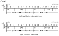
- FIG. 6 to FIG. 8 illustrate examples of periodic reporting of channel information.
- the following drawings are mostly based upon the case of transmitting downlink channel information (e.g., CQI, PMI, RI, etc.) for simplicity, the examples may also be applied to the case of transmitting uplink channel information (e.g., SRS, etc.).
- downlink channel information e.g., CQI, PMI, RI, etc.
- uplink channel information e.g., SRS, etc.
- FIG. 6 illustrates an example of transmitting channel information when the user equipment is signaled with an information indicating ⁇ period '5', offset '1' ⁇ .
- the user equipment when receiving information indicating that the cycle period is '5' and that the offset is '1', the user equipment transmits channel information in five(5) subframe units starting from a 0th subframe in an increasing direction of the subframe index with the offset of one(1) subframe.
- the channel information is essentially transmitted through the PUCCH. However, if a PUSCH exists, wherein the PUSCH is used for transmitting data at the same time as the PUCCH, the channel information is transmitted through the PUSCH along with the data.
- the subframe index is configured of a combination of a system frame number (nf) and a slot index (n s , 0 ⁇ 19). Since the subframe consists of two(2) slots, the subframe index may be defined as 10 ⁇ n f +floor(n s /2). Herein, the floor() indicates a floor function.
- FIG. 7 illustrates an example of a system having a system band configured of sixteen(16) RBs.
- the system band consists of two(2) BPs (Bandwidth Parts), that each BP is configured of two(2) SBs (subbands) (SB0, SB1), and that each SB consists of four(4) RBs.
- SB0, SB1 subbands
- SB0, SB1 subbands
- each SB consists of four(4) RBs.
- the above-mentioned assumption is merely exemplary, and, therefore, depending upon the size of the system band, the number of BPs and the size of the SBs may vary. Also, depending upon the number of RBs, the number of BPs, and the size of the SBs, the number of SBs configuring each BP may also vary.
- the WB CQI and the SB CQI are alternately transmitted. Meanwhile, in case of the type transmitting also the PMI depending upon the PMI feedback type, the PMI information is transmitted along with the CQI information.
- FIG. 8 illustrates an example of transmitting both WB CQI and SB CQI when the user equipment is signaled with an information indicating ⁇ period '5', offset '1' ⁇ .
- the CQI may only be transmitted in a subframe corresponding to the signaled cycle period and offset.
- FIG. 8(a) illustrates an example wherein only the CQI is transmitted
- FIG. 8(b) illustrates an example wherein the CQI is transmitted along with the RI.
- the RI which consists of a combination of the multiple of WB CQI transmission cycle period by which the RI is being transmitted and an offset of the corresponding cycle period, may be signaled from an upper layer (e.g., RRC layer).
- RRC layer e.g., RRC layer
- the RI transmission cycle period is a one(1) time multiple of the WB CQI transmission cycle period, and that the RI offset is '-1'. In case the transmission subframe of the WB CQI and the RI overlap, the WB CQI is dropped, and the RI is transmitted.
- FIG. 9 illustrates an example of performing communication under a multiple component carrier situation.
- the LTE-A system uses a carrier aggregation (or bandwidth aggregation) technology, which gathers multiple up-/downlink frequency blocks so as to use a larger up-/downlink bandwidth.
- Each frequency block is transmitted by using a component carrier (CC).
- CC component carrier
- the component carrier (CC) may refer to a frequency block for carrier aggregation or a center carrier of the frequency block, and such definitions may be alternately used herein.
- each of the uplink and downlink may be gathered in each of the uplink and downlink, so as to support a 100MHz bandwidth.
- Each of the CCs may be adjacent or non-adjacent to one another in the frequency domain.
- FIG. 9 illustrates a case where the bandwidth of an uplink component carrier and the bandwidth of a downlink component carrier are both identical and symmetrical to one another.
- the bandwidth of each component carrier may be independently decided.
- the bandwidth of the uplink component carrier may be configured as 5MHz(UL CC0) + 20MHz(UL CC1) + 20MHz(UL CC2) + 20MHz(UL CC3) + 5MHz(UL CC4).
- an asymmetrical carrier aggregation wherein the number of uplink component carriers and the number of downlink component carriers are different from one another, may also be performed.
- the asymmetrical carrier aggregation may be caused by a limit in available frequency bands or artificially created by network settings. For example, even if the overall system band is configured of N number of CCs, the frequency band that can be received by one specific user equipment may be limited to M( ⁇ N) number of CCs.
- M( ⁇ N) number of CCs M( ⁇ N) number of CCs.
- the embodiments of the present invention are mostly described with respect to the case where N number of CCs is applied, for simplicity. However, it is also apparent that the embodiments may be applied to a case where M number of CCs is applied.
- the N (or M) number of CCs assigned to the user equipment is divided into L number of CC groups, and the embodiments of the present invention may also be applied to each CC group.
- the base station limits a general (or normal) control/data reception to only one DL CC or some DL CCs among the total DL CCs of the system.
- the base station may assign (or allocate) DL CCs so that the reception can be limited.
- DL CC(s) assigned (or allocated) so that the general (or normal) control/ data reception can be performed with respect to a certain user equipment is/are defined as active DL CC(s).
- the remaining DL CC(s) is/are defined as non-active DL CC(s).
- a base station controlling a cell configured of 5 DL CCs may assign only one DL CC to a certain user equipment as the active DL CC and may assign the remaining 4 DL CCs as the non-active DL CCs.
- the active/ non-active DL CCs may be assigned semi-statically or dynamically. And, in order to do so, RRC signaling, L1/L2 control signaling (e.g., PDCCH), or a separately defined signaling may be used.
- the active/non-active DL CCs may be assigned by using a channel condition (or status), required amount of downlink traffic, downlink traffic, or any combination of the above.
- active/non-active DL CCs may be used along with its equivalent terms, such as available/non-available DL CCs or activated/deactivated DL CCs.
- the base station may configure (or set-up) a semi-static or dynamic linkage between a specific UL CC and a specific DL CC, so as to signal the user equipment.
- the linkage relation between the DL CC and the UL CC may be configured (or set-up) by Cell-specific or UE-specific RRC signaling or L1/L2 control signaling (e.g., PDCCH).
- the present invention proposes a method of automatically configuring (or setting-up) the state of the UL CC in synchronization with the state of the DL CC linked with the UL CC.
- the UL CC linked with the corresponding DL CC is automatically configured to be able to perform transmission of an uplink signal.
- such UL CC may be referred to as an available UL CC, and it can be said that the corresponding UL CC is in an available state.
- the UL CC linked to the corresponding DL CC is automatically configured not to perform transmission of all or some uplink signals.
- such UL CC may be referred to as a non-available UL CC, and it can be said that the corresponding UL CC is in a non-available state.
- available/non-available UL CCs may be used along with its equivalent terms, such as active/ non-active UL CCs or activated/deactivated UL CCs.
- the UL CC linked to the corresponding DL CC is also automatically semi-statically or dynamically configured as an available/ non-available UL CC.
- the UL CC may be semi-statically or dynamically shifted to an available/non-available state depending upon the state of the DL CC within the time axis.
- the available/non-available UL CC configurations (or settings) of the UL CC in accordance with the active/non-active DL CC assignment of the DL CC may not necessarily exist at the same timing, and, accordingly, there may exist a predetermined timing interval.
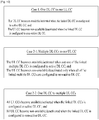
- FIG. 10 illustrates an example of configuring (or setting) a UL CC state depending upon a mapping (i.e., linkage) relation between the UL CC and the DL CC.
- Case 1 shows an example wherein the DL CC and the UL CC are mapped in a one-to-one (one DL CC to one UL CC) correspondence.
- Case 2 shows as example wherein the DL CC and the UL CC are mapped in a multiple-to-one (multiple DL CCs to one UL CC) correspondence.
- Case 3 shows an example wherein the DL CC and the UL CC are mapped in a one-to-multiple (one DL CC to multiple UL CCs) correspondence.
- the asymmetrical mapping examples, such as Case 2 and Case 3 may occur in an asymmetrical carrier aggregation environment.
- the UL CC when a linked DL CC is assigned as an active DL CC, the UL CC is automatically configured (or set-up) as an available UL CC, and when a linked DL CC is assigned as a non-active DL CC, the UL CC is automatically configured (or set-up) as a non-available UL CC.
- the UL CC may be automatically configured as an available UL CC.
- the corresponding UL CC may be configured as a non-available UL CC.
- the corresponding UL CC may be configured as a non-available UL CC.
- all linked UL CCs are configured as available UL CCs.
- all linked UL CCs may be configured as non-available UL CCs.
- the uplink transmission time of some of the uplink signals is decided based upon a predetermined configuration/timing. For example, when receiving downlink data, an ACK/NACK signal respective to the downlink data is automatically transmitted after a predetermined time has elapsed from the downlink data reception point. Also, the user equipment periodically reports channel information on downlink (e.g., CQI, PMI, RI, etc.) to the base station, and the user equipment also periodically transmits uplink signals (e.g., SRS) so that the base station can measure the channel status of the uplink.
- channel information on downlink e.g., CQI, PMI, RI, etc.
- uplink signals e.g., SRS
- uplink signals associated with the downlink or preferably, by using CQI as a main example of downlink channel information, and by using SRS a main example of a signal associated with uplink.
- Configuration information for transmitting CQI, SRS, and so on e.g., cycle period, offset, transmission band, whether or not hopping is performed, etc.
- the user equipment When a cell is configured of multiple UL CCs, the user equipment should transmit SRS for uplink channel status measurement of the multiple UL CCs to the base station, and the user equipment should also transmit CQI information for each DL CC.
- CQI or SRS
- a transmission cycle is given by RRC signaling, and once such signaling is performed, transmission should be performed in accordance with the signaled transmission cycle during a predetermined period (e.g., until the settings are changed or cancelled).
- a DL CC may be statically or semi-statically assigned as an active/non-active DL CC, and, a UL CC may be automatically configured as an available/non-available UL CC depending upon a state of a linked DL CC as explained in Embodiment 1.
- a UL CC may be independently configured as an available/non-available UL CC, by using RRC signaling, L1/L2 control signaling (e.g., PDCCH), or a separately defined signaling, without relying on the state of a DL CC linked to the UL CC.
- the corresponding DL/UL CC is configured to be in a non-active (non-available) state at the time when an uplink signal (e.g., CQI, SRS, etc.) is to be transmitted in accordance with the configuration information
- an uplink signal e.g., CQI, SRS, etc.
- the operation for transmitting the uplink signal and the operation according to the definition of the non-active (non-available) DL/UL may be the opposite of one another, a method for resolving such problem is required.
- the corresponding UL CC when the corresponding UL CC is configured to be in a non-available state at a CQI (or SRS) transmission time, a method of giving priority to the CQI (or SRS) transmission and configuring the non-available UL CC to an available UL CC in accordance with the CQI (or SRS) transmission cycle may be considered.
- the DL CC linked to the corresponding UL CC should be assigned as an active DL CC. Therefore, a reduction in battery power consumption through non-active DL CC configurations cannot be largely obtained.
- the present invention proposes to change the configuration (e.g., transmission time/pattern/band) for transmitting uplink signals so as to perform limited transmission, or not to transmit uplink signals.
- FIG. 11 shows an example of the user equipment controlling the uplink signal transmission in a carrier aggregation condition according to an embodiment of the present invention.
- the user equipment may (semi-statically) receive a parameter for deciding/identifying an uplink physical channel (signal) assignment from the base station (S1110, option).
- the uplink signal includes a signal, e.g., CQI, PMI, RI, SRS, etc., being periodically transmitted.
- the parameter being received from the base station includes cycle period information, offset information, band, and so on, for transmitting the uplink signal.
- the user equipment performs a procedure for deciding/identifying the uplink physical channel (signal) assignment (S1120). Through this procedure, a UL CC index, an uplink transmission time (e.g., UL subframe index), and so on for transmitting the uplink physical channel (signal) may be decided.
- the user equipment may not transmit the uplink physical channel (signal) (S1130, option (a)). More specifically, a user equipment, which is assigned with a transmission cycle period of the CQI (or SRS) for each CC via RRC signaling, transmits the CQI (or SRS), only when the transmission cycle period of the CQI (or SRS) matches the time when the corresponding UL CC is configured as an available UL CC.
- the user equipment does not transmit the CQI (or SRS).
- the user equipment may transmit the uplink physical channel (signal) by using a method other than the initial configuration (parameter) (e.g., changing the cycle period, changing the pattern) (S1130, option (b)).
- a method other than the initial configuration (parameter) e.g., changing the cycle period, changing the pattern
- S1130, option (b) e.g., changing the cycle period, changing the pattern
- FIG. 12 shows an example of controlling the uplink transmission in consideration of the state of the UL CC. It is assumed in FIG. 12 that a cell is configured of 3 CCs. In the drawing, although the CC may be interpreted as DL CC or UL CC, in the following description, the CC is assumed to be a UL CC. In this embodiment of the present invention, with respect to a user equipment, in case of CC#1, the UL CC is always configured as an available UL CC. And, in case of CC#0 and CC#2, it is assumed that the UL CC is dynamically configured as an available/non-available UL CC depending upon the channel state and cell traffic load condition. Herein, it is assumed that 5, 3, and 4 subframes are respectively assigned as the transmission cycle period of the CQI (or SRS) for CC#1, CC#2, and CC#3.
- CQI or SRS
- the CQI (or SRS) is always transmitted for each set of 3 subframes in accordance with the predetermined transmission cycle period.
- the CQI (or SRS) is transmitted only when the corresponding CC# at a reserved transmission time (e.g., subframe) is assigned as an available UL CC in accordance with the transmission cycle period. And, in other case, the CQI (or SRS) is not transmitted.
- a user equipment performs of determining physical uplink channel assignment for a transmission of the CQI (or SRS) at a subframe on which the CQI (or SRS) shall be transmitted, in which the CQI (or SRS) is configured not to be transmitted when a corresponding UL CC is in a state of non-available UL CC. That is, when the corresponding UL CC in a state of non-available UL CC, the user equipment may not assign a physical channel to the CQI (or SRS) at the corresponding subframe.
- the procedure of determining physical channel assignment includes assigning uplink signals (e.g., the CQI (or SRS)) to a PUSCH or a PUCCH.
- the present invention merely corresponds to one of the many examples for describing the present invention. And, this example may be applied to the present invention regardless of the number of CCs, reporting cycle period, and so on. Also, the present invention may also be applied in cases for transmitting periodic or aperiodic signals other than the CQI (or SRS).
- the base station assigns the DL CC linked to the corresponding UL CC as an active DL CC, so that the corresponding CC can be configured as an available UL CC in the CQI and SRS transmission cycle period, may be used.
- an additional signaling may be defined, wherein the additional signaling does not assign a DL CC linked to the corresponding UL CC as an active DL CC, and wherein the additional signaling configures the corresponding UL CC as an available CC only at that specific time.
- the additional signaling for the UL CC may be performed through a specific DL CC (e.g., anchor or primary DL CC), which is always being maintained in an active state in order to transmit the downlink control information.
- the CQI corresponds to information indicating the channel state of the DL CC
- the CQI is not required to be always transmitted through each UL CC.
- the CQI transmission which is shown to be respectively transmitted through CC#1 ⁇ CC#3, may be performed through one specific UL CC (e.g., anchor or primary UL CC).
- the CQI (or SRS) is transmitted through multiple UL CCs
- uplink information related to the DL CC or, preferably, when transmitting downlink channel information (e.g., CQI) for the DL CC
- downlink channel information e.g., CQI
- CQI information for multiple DL CCs may be transmitted through one UL CC (e.g., anchor or primary UL CC).
- multiple CQI may be transmitted in a TDM (Time Division Multiplexing) method by adjusting the transmission cycle period between the UL CCs.
- TDM Time Division Multiplexing
- multiple CQIs may be simultaneously transmitted through multiple UL CC.
- CQI transmission may be performed by using many other methods. Only one transmission method may be used but, in some cases, a plurality of transmission methods may also be used.
- the present invention proposes a method of deciding the transmission or non-transmission of the CQI depending upon the active/non-active CC assignment of the DL CC, regardless of the CQI transmission method. More specifically, a CQI transmission cycle period, a timing offset, a UL CC that is to be transmitted, etc. are configured in advance for all of the assigned DL CCs, and when the CQI that is to be transmitted is associated with the active CC, the CQI is transmitted. And, when the CQI that is to be transmitted is associated with the non-active CC, the CQI is not transmitted.
- the exemplary condition given in S1130 of FIG. 11 may be changed to "if the uplink physical channel (signal) that is to be transmitted at the corresponding time is related to the non-active duration (or portion) of the DL CC.”
- FIGs. 13-15 show examples of controlling uplink transmission in accordance with the DL CC state.
- active/non-active assignment is applied only to the DL CC and not applied to the UL CC.
- the UL CC may always transmit signals regardless of the state of the DL CC.
- configuring the UL CC to an available/non-available state is not excluded.
- the present invention may also be applied in cases where the UL CC is configured to an available/non-available state as time goes by.
- FIG. 13 shows a case wherein a CQI transmission cycle period is separately configured for each DL CC, and wherein the CQI for multiple DL CCs is respectively transmitted through multiple UL CCs.
- the DL CC is assigned as an active/non-active CC, whether or not to transmit the CQI related to the corresponding DL CC is also decided.
- the time when the CQI related to the DL CC#0 is transmitted is configured as subframe number 1, subframe number 5, subframe number 9, and subframe number 13 in UL CC#0.
- DL CC#0 is assigned as a non-active CC in subframe number 5.
- the CQI related to DL CC#0 is transmitted only through subframe number 1, subframe number 9, and subframe number 13 in UL CC#0, and the CQI is not transmitted through subframe number 5.
- a user equipment performs a procedure of determining physical uplink channel assignment for a transmission of the CQI at a subframe on which the CQI shall be transmitted, in which the CQI is configured not to be transmitted when a corresponding UL CC is in a state of non-available UL CC. That is, when the corresponding UL CC in a state of non-available UL CC, the user equipment may not assign a physical channel to the CQI at the corresponding subframe.
- an index of a downlink subframe, wherein the downlink channel is actually measured, and an index of an uplink subframe, wherein the CQI is transmitted may be different from one another.
- the CQI being transmitted through subframe number 5 of UL DC#0 may be related to the channel quality of subframe number 3 in DL CC#0 (i.e., a difference of 2 subframes).
- whether or not to transmit the CQI through subframe number 5 of UL CC#0 may be decided based upon whether or not subframe number 3 of DL CC#0 is configured as a non-active state.
- FIG. 14 shows a case wherein a CQI transmission cycle period is separately configured for each DL CC, and wherein the CQI for multiple DL CCs is transmitted through a single UL CC.
- the DL CC is assigned as an active/non-active CC, whether or not to transmit the CQI related to the corresponding DL CC is also decided.
- a specific UL CC configured so that CQI for multiple DL CCs can be transmitted may be referred to as an anchor or primary UL CC.
- the time when the CQI related to the DL CC#0 is transmitted is configured as subframe number 1, subframe number 5, subframe number 9, and subframe number 13 in UL CC#1.
- DL CC#0 is assigned as a non-active CC in subframe number 5. Therefore, the CQI related to DL CC#0 is transmitted only through subframe number 1, subframe number 9, and subframe number 13 in UL CC#1, and the CQI is not transmitted through subframe number 5.
- UL CC#1 may send CQI information corresponding to each DL CC depending upon the active/ non-active CC assignment for DL CC#1 and DL CC#2.
- subframe number 9 corresponds to the CQI transmission time of two DL CCs (DL CC#0, DL CC#2).
- FIG. 15 shows a case wherein the CQI for multiple DL CCs is respectively transmitted to multiple UL CCs, yet wherein, considering the transmission cycle period/offset between the CCs, the overall transmission is performed by using the TDM method.
- the remaining process is identical to those described in FIG. 13 and FIG. 14 . Therefore, since reference may be made to FIG. 13 and FIG. 14 , detailed description of the same will be omitted for simplicity.
- the present invention may also be applied to other diverse methods of the CQI transmission method in addition to the above-described examples.
- the DL subframe index and the UL subframe index are used to facilitate the description of the present invention. Accordingly, identical DL/ UL subframe indexes do not necessarily signify subframes at the same time point. In other words, a timing of a predetermined time interval may exist between the DL subframe and the UL subframe.
- This embodiment of the present invention proposes a method of transmitting CQI to the corresponding UL CC depending upon a predetermined configuration, when the time point corresponding to the transmission cycle period of the CQI matches with the time point where the DL CC is assigned as an active CC, and transmitting CQI by using another configuration, when the DL CC is assigned as a non-active CC at the time corresponding to the transmission cycle period of the CQI.
- the user equipment may use another configuration (parameter) for the CQI (e.g., transmission cycle period/ pattern/measurement band etc.) differently from the predetermined configuration.
- This embodiment of the present invention may be used along with a CQI transmission stop operation proposed in Embodiment 2-2, or may be used optionally. More specifically, when the DL CC is configured as an active CC, the user equipment may perform CQI transmission in accordance with the predetermined CQI configuration, and, then, when the corresponding DL CC is configured as a non-active CC, the CQI transmission may be stopped (SRS off), as proposed in Embodiment 2-2, or the CQI may be transmitted in accordance with the modified configuration.
- SRS off SRS off
- FIG. 16 illustrates an example of controlling uplink transmission of the CQI according to an embodiment of the present invention.
- the CQI cycle period is 2ms (2 subframes) and that 2 BW parts (BP1 ⁇ 2) exist within a WB.
- the CQI is transmitted for each 2ms in the order of WB ⁇ BPI ⁇ BP2.
- the CQI may be transmitted in accordance with the following modified methods. The methods described below are given to facilitate the understanding of the present invention, and each method may be used independently or in combination.
- Signaling for the embodiment of the present invention may be diversely implemented.
- the signaling for the embodiment of the present invention may be included in a control signal (e.g., L1/L2 control signaling or RRC signaling) for configuring active/non-active CC, so as to be transmitted.
- a control channel e.g., PDCCH
- changing the CQI parameter for non-active DL CC may be separately configured.
- 1-bit signaling may be performed.
- modified CQI transmission cycle period/pattern/measurement band values which are predetermined for non-active CCs may be applied based upon the 1-bit signaling, or the modified CQI transmission cycle period/ pattern/measurement band values may be directly signaled.
- a method of selecting/combining the CQI off and Methods 1-1 ⁇ 1-4 may also be used in accordance with one field.
- 2 CQI configurations, which are to be applied to active and non-active CCs in Methods 1-1 ⁇ 1-4 may both be predetermined.
- at least one of the transmission cycle period/pattern/measurement band may be configured in pairs in a common signaling information.
- An SRS is a signal transmitted from the user equipment to the base station in order to be informed of the uplink channel state. Therefore, even when the DL CC is assigned as a non-active CC, and even in a condition wherein the user equipment does not receive data via downlink, for the scheduling for an uplink data transmission of the user equipment, the base station should be informed of the uplink channel information of each UL CC. Accordingly, whether or not to transmit the SRS may be decided in accordance with the active/non-active state (or activation/non-activation) of the UL CC that is to be transmitted, regardless of the active/non-active CC assignment of the DL CC.
- the active/non-active state (or activation/non-activation) of the UL CC may be dynamically or semi-statically modified.
- the active state of the UL CC may be referred to as an activated UL CC
- the non-active state of the UL CC may be referred to as a deactivated UL CC.
- the deactivated UL CC may be defined as described in the example shown in Embodiment 1.
- the deactivated UL CC may be defined as a UL CC configured to have a limited transmission only for the uplink data channel (e.g., PUSCH), or as a UL CC configured to have a limited transmission (e.g., PUCCH) of some control information along with the data transmission.
- a UL CC configured to have a limited transmission only for the uplink data channel (e.g., PUSCH), or as a UL CC configured to have a limited transmission (e.g., PUCCH) of some control information along with the data transmission.
- this embodiment of the present invention proposes a method of transmitting SRS on the corresponding UL CC depending upon a predetermined configuration, when the time point corresponding to the transmission cycle period of the SRS matches with the time when the UL CC is assigned as an active CC, and transmitting SRS by using another configuration, when the UL CC is assigned as a non-active CC at the time corresponding to the transmission cycle period of the SRS.
- the user equipment may use another configuration (parameter) for the SRS (e.g., transmission cycle period/pattern/measurement band etc.) differently from the predetermined configuration.
- the method of modifying activation/ deactivation of the UL CC is not limited.
- the UL CC may be activated/ deactivated separately from the DL CC, or the UL CC may be activated/deactivated in accordance with the active/non-active CC assignment for the DL CC. Therefore, when the active/non-active state of the UL CC is decided by the DL CC linked to the corresponding UL CC, the modification of the parameter for SRS transmission may be applied to the UL CC linked to the non-active DL CC.
- the modification of the parameter for SRS transmission may be applied to the non-active UL CC.
- the transmission cycle period of the SRS may be independently assigned among the UL CCs.
- the cycle period among multiple UL CCs may be adjusted in order to perform assignment so that transmission can be performed by using the TDM method. Additionally, the assignment may be performed by using other diverse methods.
- the embodiment of the present invention may be used along with the SRS transmission stop operations proposed in Embodiment 2-1, or the embodiment of the present invention may be used optionally. More specifically, when the UL CC is configured as an active CC, the user equipment may perform SRS transmission in accordance with the predetermined SRS configuration. Then, when the corresponding UL CC is configured as an inactive CC, as proposed in Embodiment 2-1, the SRS transmission may be stopped (SRS off) or transmission may be performed in accordance with a modified SRS configuration.
- FIG. 17 shows an example of controlling an uplink transmission of an SRS according to the embodiment of the present invention
- an SRS cycle period is 2ms (2 subframes) and 4 SRS BWs (SB1 ⁇ 4) exist within an SRS hopping BW (WB).
- the SRS is transmitted at each 2ms, and frequency hopping is performed in the order of SB 1 ⁇ SB3 ⁇ SB2 ⁇ SB4.
- the SRS may be transmitted in accordance with the following modified methods.
- the methods described below are given to facilitate the understanding of the present invention, and each method may be used independently or in combination.
- Signaling for the embodiment of the present invention may be diversely implemented in accordance with the active/non-active UL CC configuration method. For example, when the UL CC is activated/deactivated by the active/non-active CC assignment of the DL CC, the signaling for the embodiment of the present invention may be performed through a control signal (e.g., L1/L2 control signaling or RRC signaling) for configuring active/non-active DL CC.
- a control signal e.g., L1/L2 control signaling or RRC signaling
- the signaling for the embodiment of the present invention may be performed through a control signal (e.g., L1/L2 control signaling or RRC signaling) for configuring active/non-active UL CC.
- a control signal e.g., L1/L2 control signaling or RRC signaling
- a control channel e.g., PDCCH
- PDCCH PDCCH
- 1-bit signaling may be performed.
- modified SRS transmission cycle period/pattern/transmission band values which are predetermined for non-active UL CCs may be applied based upon the 1-bit signaling, or the modified SRS transmission cycle period/ pattern/transmission band values may be directly signaled.
- a method of selecting/ combining the SRS off and Methods 2-1 ⁇ 2-4 may also be used in accordance with one field.
- 2 SRS configurations, which are to be applied to active and non-active UL CCs in Methods 2-1 ⁇ 2-4 may both be predetermined.
- at least one of the transmission cycle period/pattern/transmission band may be configured in pairs in a common signaling information.
- FIG. 18 illustrates exemplary base station and user equipment that can be applied to the embodiment of the present invention.
- a wireless communication system includes a base station (BS) (110) and a user equipment (UE) (or terminal) (120).
- a transmitter corresponds to a portion of the base station (110), and a receiver corresponds to a portion of the UE (120).
- a transmitter corresponds to a portion of the UE (120), and a receiver corresponds to a portion of the base station (110).
- the base station (110) includes a processor (112), a memory (114), and a radio frequency (RF) unit (116).
- the processor (112) may be configured to embody the procedures and/or methods proposed in the present invention.
- the memory (114) is connected to the processor (112) and stores diverse information associated with the operation of the processor (112).
- the RF unit (116) is connected to the processor (112) and transmits and/or receives a radio signal.
- the UE (or terminal) (120) includes a processor (122), a memory (124), and an RF unit (126).
- the processor (122) may be configured to embody the procedures and/or methods proposed in the present invention.
- the memory (124) is connected to the processor (122) and stores diverse information associated with the operation of the processor (122).
- the RF unit (126) is connected to the processor (122) and transmits and/or receives a radio signal.
- the base station (110) and/or the UE (120) may have a single antenna or multiple antennae.
- the embodiments of the present invention have been described based on the data transmission and reception between the base station and the user equipment.
- a specific operation which has been described as being performed by the base station may be performed by an upper node of the base station as the case may be.
- various operations performed for communication with the user equipment in the network which includes a plurality of network nodes along with the base station can be performed by the base station or network nodes other than the base station.
- the base station may be replaced with terms such as a fixed station, Node B, eNode B (eNB), and access point.
- the user equipment may be replaced with terms such as mobile station (MS) and mobile subscriber station (MSS).
- the embodiments according to the present invention can be implemented by various means, for example, hardware, firmware, software, or their combination. If the embodiment according to the present invention is implemented by hardware, the embodiment of the present invention can be implemented by one or more application specific integrated circuits (ASICs), digital signal processors (DSPs), digital signal processing devices (DSPDs), programmable logic devices (PLDs), field programmable gate arrays (FPGAs), processors, controllers, microcontrollers, microprocessors, etc.
- ASICs application specific integrated circuits
- DSPs digital signal processors
- DSPDs digital signal processing devices
- PLDs programmable logic devices
- FPGAs field programmable gate arrays
- processors controllers, microcontrollers, microprocessors, etc.
- the embodiment of the present invention may be implemented by a type of a module, a procedure, or a function, which performs functions or operations described as above.
- a software code may be stored in a memory unit and then may be driven by a processor.
- the memory unit may be located inside or outside the processor to transmit and receive data to and from the processor through various means which are well known.
- the present invention may be applied to a wireless communication system. More specifically, the present invention may be applied to a communication method using a carrier aggregation and apparatus therefore.
Claims (6)
- Verfahren zur Steuerung einer Uplink-Übertragung an einem Benutzergerät (120) in einem drahtlosen Kommunikationssystem, wobei das Benutzergerät (120) mit mehreren Uplink-Komponententrägern konfiguriert wird, wobei das Verfahren umfasst:Empfangen (S1110), aus einer Basisstation (110), von RRC-Konfigurationsinformationen (RRC = Funkressourcensteuerung) für ein Sondierungsbezugssignal (SRS), wobei die RRC-Konfigurationsinformationen Informationen zum periodischen Übertragen des SRS an die Basisstation (110) einschließen;dadurch gekennzeichnet, dass das Verfahren ferner einschließt:wobei ein normaler Signalempfang durch das Benutzergerät (120) auf einem Downlink-Komponententräger, gepaart mit einem Uplink-Komponententräger im verfügbaren Zustand, erfolgt und ein begrenzter Signalempfang durch das Benutzergerät (120) auf einem Downlink-Komponententräger, gepaart mit einem Uplink-Komponententräger im nicht verfügbaren Zustand, erfolgt.Durchführen einer Prozedur (S1130) zum periodischen Übertragen des SRS an die Basisstation (110) auf einem Uplink-Komponententräger der mehreren Uplink-Komponententräger unter Verwendung der RRC-Konfigurationsinformationen,wobei, falls sich der Uplink-Komponententräger zu einem Zeitpunkt für eine Übertragung des SRS in einem verfügbaren Zustand befindet, zu dem Zeitpunkt für eine Übertragung des SRS eine SRS-Übertragung auf dem Uplink-Komponententräger erfolgt,wobei, falls sich der Uplink-Komponententräger zu dem Zeitpunkt für eine Übertragung des SRS in einem nicht verfügbaren Zustand befindet, zu dem Zeitpunkt für eine Übertragung des SRS die SRS-Übertragung auf dem Uplink-Komponententräger übersprungen wird,wobei die verfügbaren/nicht verfügbaren Zustände des Uplink-Komponententrägers unter Verwendung einer Schicht-1- oder Schicht-2-Steuersignalisierung (L1/L2-Steuersignalisierung) gesteuert werden und
- Verfahren nach Anspruch 1, wobei unter Verwendung eines Zustandes eines mit dem Uplink-Komponententräger verbundenen Downlink-Komponententrägers identifiziert wird, ob sich der Uplink-Komponententräger in einem nicht verfügbaren Zustand befindet oder nicht.
- Verfahren nach Anspruch 2, wobei der Uplink-Komponententräger als nicht verfügbarer Zustand konfiguriert wird, wenn sich mehrere mit dem Uplink-Komponententräger verbundene Downlink-Komponententräger alle in einem nicht verfügbaren Zustand befinden.
- Benutzergerät (120), das so konfiguriert ist, dass es mit einer Basisstation (110) unter Verwendung von mehreren Uplink-Komponententrägern eines drahtlosen Kommunikationssystems kommuniziert, wobei das Benutzergerät (120) umfasst:eine HF-Einheit (126) (HF = Hochfrequenz), die so konfiguriert ist, dass sie Drahtlossignale an die und aus der Basisstation (110) überträgt und empfängt;einen Speicher (124), der so konfiguriert ist, dass er an die und aus der Basisstation (110) übertragene und empfangene Informationen und für die Durchführung von Operationen des Benutzergeräts (120) erforderliche Parameter speichert; undeinen Prozessor (122), der so konfiguriert ist, dass er an die HF-Einheit und den Speicher angeschlossen ist, und so konfiguriert ist, dass er die HF-Einheit (126) und den Speicher (124) steuert, um das Benutzergerät (120) zu betreiben,wobei der Prozessor (122) so konfiguriert ist, dass er aus einer Basisstation (110) RRC-Konfigurationsinformationen (RRC = Funkressourcensteuerung) für ein Sondierungsbezugssignal (SRS) aus der Basisstation (110) empfängt (S1110), wobei die RRC-Konfigurationsinformationen Informationen zum periodischen Übertragen des SRS an die Basisstation (110) einschließen;
dadurch gekennzeichnet, dass der Prozessor ferner so konfiguriert ist, dass er eine Prozedur (S1130) zum periodischen Übertragen des SRS an die Basisstation (110) auf einem Uplink-Komponententräger der mehreren Uplink-Komponententräger unter Verwendung der RRC-Konfigurationsinformationen durchführt,wobei, falls sich der Uplink-Komponententräger zu einem Zeitpunkt für eine Übertragung des SRS in einem verfügbaren Zustand befindet, zu dem Zeitpunkt für eine Übertragung des SRS eine SRS-Übertragung auf dem Uplink-Komponententräger erfolgt,wobei, falls sich der Uplink-Komponententräger zu dem Zeitpunkt für eine Übertragung des SRS in einem nicht verfügbaren Zustand befindet, zu dem Zeitpunkt für eine Übertragung des SRS die SRS-Übertragung auf dem Uplink-Komponententräger übersprungen wird,wobei die verfügbaren/nicht verfügbaren Zustände des Uplink-Komponententrägers unter Verwendung einer Schicht-1- oder Schicht-2-Steuersignalisierung (L1/L2-Steuersignalisierung) gesteuert werden undwobei ein normaler Signalempfang durch das Benutzergerät (120) auf einem Downlink-Komponententräger, gepaart mit einem Uplink-Komponententräger im verfügbaren Zustand, erfolgt und ein begrenzter Signalempfang durch das Benutzergerät (120) auf einem Downlink-Komponententräger, gepaart mit einem Uplink-Komponententräger im nicht verfügbaren Zustand, erfolgt. - Benutzergerät (120) nach Anspruch 4, wobei unter Verwendung eines Zustandes eines mit dem Uplink-Komponententräger verbundenen Downlink-Komponententrägers identifiziert wird, ob sich der Uplink-Komponententräger in einem nicht verfügbaren Zustand befindet oder nicht.
- Benutzergerät (120) nach Anspruch 5, wobei der Uplink-Komponententräger als nicht verfügbarer Zustand konfiguriert ist, wenn sich mehrere mit dem Uplink-Komponententräger verbundene Downlink-Komponententräger alle in einem nicht verfügbaren Zustand befinden.
Applications Claiming Priority (5)
| Application Number | Priority Date | Filing Date | Title |
|---|---|---|---|
| US18518509P | 2009-06-08 | 2009-06-08 | |
| US18763409P | 2009-06-16 | 2009-06-16 | |
| US30083310P | 2010-02-03 | 2010-02-03 | |
| KR1020100030753A KR101119119B1 (ko) | 2009-06-08 | 2010-04-05 | 반송파 집성을 이용한 통신 방법 및 이를 위한 장치 |
| PCT/KR2010/003112 WO2010143821A2 (en) | 2009-06-08 | 2010-05-17 | Communication method using a carrier aggregation and apparatus therefore |
Publications (3)
| Publication Number | Publication Date |
|---|---|
| EP2441192A2 EP2441192A2 (de) | 2012-04-18 |
| EP2441192A4 EP2441192A4 (de) | 2017-01-11 |
| EP2441192B1 true EP2441192B1 (de) | 2018-05-02 |
Family
ID=43507805
Family Applications (1)
| Application Number | Title | Priority Date | Filing Date |
|---|---|---|---|
| EP10786304.5A Active EP2441192B1 (de) | 2009-06-08 | 2010-05-17 | Kommunikationsverfahren mit trägeraggregation und vorrichtung dafür |
Country Status (6)
| Country | Link |
|---|---|
| US (7) | US8331401B2 (de) |
| EP (1) | EP2441192B1 (de) |
| JP (2) | JP5636045B2 (de) |
| KR (1) | KR101119119B1 (de) |
| CN (2) | CN102461030B (de) |
| WO (1) | WO2010143821A2 (de) |
Families Citing this family (40)
| Publication number | Priority date | Publication date | Assignee | Title |
|---|---|---|---|---|
| US20120093119A1 (en) * | 2009-06-18 | 2012-04-19 | So Yeon Kim | Method and apparatus for transmitting sounding reference signal in wireless communication system |
| DK3139674T3 (da) * | 2009-06-26 | 2020-04-27 | Ericsson Telefon Ab L M | Fremgangsmåder og anordninger i et telekommunikationsnetværk |
| MX2012003399A (es) * | 2009-09-30 | 2012-04-10 | Ericsson Telefon Ab L M | Reconfiguracion de conjunto de portadores de componente activo en sistemas inalambricos de portadores multiples. |
| CN102088303B (zh) * | 2010-02-11 | 2014-11-05 | 电信科学技术研究院 | Srs信号发送方法及其触发方法以及设备 |
| US8817719B2 (en) | 2010-02-22 | 2014-08-26 | Telefonaktiebolaget L M Ericsson (Publ) | Methods and arrangements for dynamically triggering the transmission of sounding reference signal in a telecommunication system |
| CN102238616B (zh) * | 2010-04-30 | 2015-09-09 | 华为技术有限公司 | 一种信息上报方法、基站以及用户设备 |
| US20110267948A1 (en) * | 2010-05-03 | 2011-11-03 | Koc Ali T | Techniques for communicating and managing congestion in a wireless network |
| KR20120047204A (ko) | 2010-11-03 | 2012-05-11 | 삼성전자주식회사 | 시분할 이중화 시스템에서의 수신 확인 정보 생성 및 전력 제어를 위한 방법 및 장치 |
| EP2475127A1 (de) * | 2011-01-10 | 2012-07-11 | Panasonic Corporation | Berichterstattung von Kanalstatusinformationen für Komponententräger, für die keine Kanalstatusinformation berechnet wurde |
| WO2012108679A2 (ko) | 2011-02-08 | 2012-08-16 | 엘지전자 주식회사 | 반송파 집성 시스템에서 스케줄링 방법 및 장치 |
| KR102073027B1 (ko) | 2011-04-05 | 2020-02-04 | 삼성전자 주식회사 | 반송파 집적 기술을 사용하는 무선통신시스템에서 복수 개의 타임 정렬 타이머 운용 방법 및 장치 |
| WO2012118343A2 (ko) * | 2011-03-02 | 2012-09-07 | 엘지전자 주식회사 | 단말의 사운딩 참조신호 전송방법 및 장치 |
| KR101785313B1 (ko) | 2011-04-12 | 2017-10-17 | 삼성전자주식회사 | 통신 시스템에서 간섭 제어를 위한 서브프레임 운용 및 채널 정보 전송 방법 및 장치 |
| US9480050B2 (en) | 2011-04-25 | 2016-10-25 | Lg Electronics Inc. | Method for configuring resource for carrier aggregation and apparatus for same |
| US10085164B2 (en) * | 2011-04-28 | 2018-09-25 | Qualcomm Incorporated | System and method for managing invalid reference subframes for channel state information feedback |
| US20130010659A1 (en) * | 2011-07-08 | 2013-01-10 | Qualcomm Incorporated | Sounding reference signals in asymmetric carrier aggregation |
| US9461793B2 (en) * | 2011-11-01 | 2016-10-04 | Lg Electronics Inc. | Method for determining the transmission of a sounding reference signal in a wireless communication system, and terminal therefor |
| WO2013141525A1 (ko) * | 2012-03-20 | 2013-09-26 | 엘지전자 주식회사 | 반송파 집성 기법이 적용된 무선 통신 시스템에서 무선 자원 동적 변경에 기반한 신호 송수신 방법 및 이를 위한 장치 |
| JP2013229830A (ja) * | 2012-04-27 | 2013-11-07 | Sharp Corp | 通信システム、基地局装置、移動局装置、測定方法、および集積回路 |
| CN103906134B (zh) | 2012-12-27 | 2018-07-20 | 电信科学技术研究院 | 一种传输上行信息的方法、设备及系统 |
| US9712262B2 (en) * | 2013-01-09 | 2017-07-18 | Lg Electronics Inc. | Method and apparatus for performing measurement in wireless communication system |
| BR112015015636B1 (pt) * | 2013-01-18 | 2023-02-14 | Telefonaktiebolaget L M Ericsson (Publ) | Métodos e nós para detectar ativação de célula servidora |
| RU2612658C2 (ru) | 2013-01-25 | 2017-03-13 | ЭлДжи ЭЛЕКТРОНИКС ИНК. | Способ и устройство для выполнения процедуры начального доступа в системе беспроводной связи |
| KR102201754B1 (ko) * | 2013-01-31 | 2021-01-12 | 엘지전자 주식회사 | 반송파 집성(carrier aggregation)을 이용한 통신 방법 및 이를 위한 장치 |
| US9642140B2 (en) * | 2013-06-18 | 2017-05-02 | Samsung Electronics Co., Ltd. | Methods of UL TDM for inter-enodeb carrier aggregation |
| JP2016076748A (ja) * | 2014-10-02 | 2016-05-12 | 富士通株式会社 | 基地局装置、無線通信システム及び基地局装置制御方法 |
| US10143005B2 (en) * | 2014-11-07 | 2018-11-27 | Qualcomm Incorporated | Uplink control resource allocation for dynamic time-division duplex systems |
| CN107431888B (zh) | 2015-04-10 | 2021-02-26 | Lg电子株式会社 | 在无线接入系统中控制探测参考信号发送的方法和装置 |
| GB2548902A (en) * | 2016-04-01 | 2017-10-04 | Tcl Communication Ltd | Cellular communication system devices and methods |
| US10588141B2 (en) | 2016-06-29 | 2020-03-10 | Qualcomm Incorporated | Multiple antennas and interruption time values for sounding reference signal (SRS) switching |
| EP3526914B1 (de) | 2016-10-11 | 2023-09-20 | Telefonaktiebolaget LM Ericsson (publ) | Verfahren und vorrichtung zur anpassung von srs-umschaltung für messverfahren |
| US10362571B2 (en) * | 2016-11-04 | 2019-07-23 | Qualcomm Incorporated | Power control and triggering of sounding reference signal on multiple component carriers |
| CN112888079A (zh) * | 2016-11-11 | 2021-06-01 | Oppo广东移动通信有限公司 | 调度终端设备的方法、网络设备和终端设备 |
| US10419196B2 (en) | 2017-05-05 | 2019-09-17 | At&T Intellectual Property I, L.P. | Virtual carrier aggregation for wideband operation of wireless communication systems |
| EP3656168A1 (de) | 2017-07-21 | 2020-05-27 | Koninklijke KPN N.V. | Auswahl eines teilsatzes von frequenzressourcen basierend auf messungen von kandidatenfrequenzressourcen |
| US10575217B2 (en) | 2017-08-11 | 2020-02-25 | Qualcomm Incorporated | Techniques and apparatuses for managing sounding reference signal (SRS) transmissions in a bandwidth part |
| EP4319035A3 (de) * | 2017-11-17 | 2024-03-06 | Lenovo (Singapore) Pte. Ltd. | Leistungsregelungskonfiguration für uplink-übertragungen |
| US10903949B2 (en) * | 2018-07-10 | 2021-01-26 | Huawei Technologies Co., Ltd. | Method and system for multiple active bandwidth parts per carrier |
| WO2020034190A1 (zh) * | 2018-08-17 | 2020-02-20 | 华为技术有限公司 | 一种资源指示方法以及装置 |
| US20210306994A1 (en) * | 2020-03-30 | 2021-09-30 | Qualcomm Incorporated | Uplink timing associated with uplink transmission configuration indication (tci) state |
Family Cites Families (43)
| Publication number | Priority date | Publication date | Assignee | Title |
|---|---|---|---|---|
| US6721569B1 (en) * | 2000-09-29 | 2004-04-13 | Nortel Networks Limited | Dynamic sub-carrier assignment in OFDM systems |
| EP1613117B1 (de) * | 2004-07-01 | 2013-05-22 | Samsung Electronics Co., Ltd. | System und Verfahren für das Übertragen von uplink Steuerinformationen in einem OFDMA Kommunikationssystem |
| US7701844B2 (en) * | 2005-02-09 | 2010-04-20 | Interdigital Technology Corporation | Method and apparatus for recognizing radio link failures associated with HSUPA and HSDPA channels |
| US8169953B2 (en) | 2005-05-17 | 2012-05-01 | Qualcomm Incorporated | Method and apparatus for wireless multi-carrier communications |
| JP2007110529A (ja) | 2005-10-14 | 2007-04-26 | Mitsubishi Electric Corp | チャネル品質伝送方法、端末および基地局 |
| KR100934656B1 (ko) * | 2006-02-06 | 2009-12-31 | 엘지전자 주식회사 | 다중 반송파 시스템에서의 무선 자원 할당 방법 |
| KR100706981B1 (ko) * | 2006-03-23 | 2007-04-12 | 에스케이 텔레콤주식회사 | 휴대인터넷망에서 이동통신 단말기의 서비스 가능 상태를파악하는 시스템 및 방법 |
| KR20090029839A (ko) * | 2006-07-14 | 2009-03-23 | 콸콤 인코포레이티드 | 그룹 통신 시스템에서 동작하는 단말로부터의 응답을 억제하기 위한 방법 및 장치 |
| US20080026744A1 (en) | 2006-07-27 | 2008-01-31 | Nokia Corporation | Providing dynamically controlled CQI technique adapted for available signaling capacity |
| JP4923848B2 (ja) | 2006-08-21 | 2012-04-25 | 日本電気株式会社 | 通信システム及び通信方法並びにそれに用いる移動局及び基地局 |
| ES2771677T3 (es) | 2006-10-03 | 2020-07-06 | Interdigital Tech Corp | Control de potencia de transmisión de enlace ascendente (basado en CQI) de bucle abierto/bucle cerrado combinado con mitigación de interferencias para E-UTRA |
| US8797889B2 (en) * | 2007-04-13 | 2014-08-05 | Telefonaktiebolaget LML Ericsson (Publ) | Multi-carrier CQI feedback method and apparatus |
| KR101325920B1 (ko) * | 2007-05-02 | 2013-11-07 | 삼성전자주식회사 | 업링크 제어 정보 전송 방법 및 이를 위한 단말 장치 |
| US8116270B2 (en) | 2007-06-13 | 2012-02-14 | Samsung Electronics Co., Ltd | Method and apparatus for transmitting and receiving channel quality indicator in communication system |
| IL185088A (en) * | 2007-08-07 | 2012-02-29 | Alvarion Ltd | Method and apparatus for synchronizing changes in power saving procedures |
| MX2010002218A (es) | 2007-10-02 | 2010-03-17 | Ericsson Telefon Ab L M | Incluida en la concesion de enlace ascendente se va a reportar una indicacion de una cantidad especifica de cqi. |
| US8189518B2 (en) | 2007-10-22 | 2012-05-29 | Sharp Laboratories Of America, Inc. | Systems and methods for using a format of an uplink control channel to transmit a channel quality indicator |
| ES2440695T3 (es) * | 2008-03-25 | 2014-01-30 | Telefonaktiebolaget L M Ericsson (Publ) | Selección de portadora de anclaje en red inalámbrica de portadoras múltiples |
| CA2722488C (en) * | 2008-04-25 | 2014-12-16 | Interdigital Patent Holdings, Inc. | Method and apparatus for simultaneously receiving on two carriers and performing discontinuous transmission and reception in dual cell high speed downlink packet access |
| US8537802B2 (en) | 2008-07-23 | 2013-09-17 | Marvell World Trade Ltd. | Channel measurements in aggregated-spectrum wireless systems |
| US8515481B2 (en) * | 2008-09-05 | 2013-08-20 | Mediatek Inc. | Power management for multi-carrier transmission |
| TWI504299B (zh) * | 2008-10-20 | 2015-10-11 | Interdigital Patent Holdings | 載波聚合上鏈控制資訊傳輸方法 |
| JP5622735B2 (ja) | 2008-10-20 | 2014-11-12 | インターデイジタル パテント ホールディングス インコーポレイテッド | キャリア集約 |
| US8514793B2 (en) * | 2008-10-31 | 2013-08-20 | Interdigital Patent Holdings, Inc. | Method and apparatus for monitoring and processing component carriers |
| EP2187691A1 (de) | 2008-11-12 | 2010-05-19 | Alcatel, Lucent | Verfahren zur Funkkommunikation zwischen einer Basisstation und einem Benutzerendgerät unter Verwendung einer Übertragung auf Komponententrägern auf der Basis von Kontrollinformation sowie Basisstation, Benutzerendgerät und Kommunikationsnetz dafür |
| WO2010059926A1 (en) * | 2008-11-21 | 2010-05-27 | Interdigital Patent Holdings, Inc. | Method and apparatus for multiple carrier utilization in wireless communications |
| TWI475856B (zh) | 2008-11-25 | 2015-03-01 | Interdigital Patent Holdings | 多數上鏈載波及多數下鏈載波利用方法及裝置 |
| CN101426225B (zh) * | 2008-12-09 | 2010-09-29 | 中兴通讯股份有限公司 | 一种终端上报信道质量指示报告的方法 |
| WO2010078365A1 (en) | 2008-12-30 | 2010-07-08 | Interdigital Patent Holdings, Inc. | Discontinuous reception for carrier aggregation |
| US9450727B2 (en) * | 2009-02-03 | 2016-09-20 | Google Technology Holdings LLC | Physical layer acknowledgement signaling resource allocation in wireless communication systems |
| US20100215011A1 (en) * | 2009-02-26 | 2010-08-26 | Interdigital Patent Holdings, Inc. | Method and apparatus for switching a resource assignment mode for a plurality of component carriers |
| JP2010212893A (ja) * | 2009-03-09 | 2010-09-24 | Sharp Corp | 移動局装置、無線通信システム、通信制御方法、及び通信制御プログラム |
| CN102349329A (zh) * | 2009-03-12 | 2012-02-08 | 交互数字专利控股公司 | 用于执行特定于分量载波的重配置的方法和设备 |
| CN102349342B (zh) | 2009-03-12 | 2014-02-26 | 交互数字专利控股公司 | 用于选择和重选上行链路主载波的方法和设备 |
| US8620334B2 (en) | 2009-03-13 | 2013-12-31 | Interdigital Patent Holdings, Inc. | Method and apparatus for carrier assignment, configuration and switching for multicarrier wireless communications |
| US8934417B2 (en) * | 2009-03-16 | 2015-01-13 | Google Technology Holdings LLC | Resource allocation in wireless communication systems |
| EP2230786A1 (de) * | 2009-03-16 | 2010-09-22 | Panasonic Corporation | Kanalqualitätsfeedback-Signalisierung in Kommunikationssystemen |
| US8514732B2 (en) | 2009-03-17 | 2013-08-20 | Qualcomm Incorporated | System and method for effectuating a signal carrier configuration |
| WO2010107880A2 (en) * | 2009-03-17 | 2010-09-23 | Interdigital Patent Holdings, Inc. | Method and apparatus for power control of sounding reference signal (srs) transmission |
| WO2010123893A1 (en) | 2009-04-22 | 2010-10-28 | Interdigital Patent Holdings, Inc. | Method and apparatus for transmitting uplink control information for carrier aggregated spectrums |
| US8437798B2 (en) * | 2009-04-27 | 2013-05-07 | Motorola Mobility Llc | Uplink scheduling support in multi-carrier wireless communication systems |
| US8565167B2 (en) * | 2009-07-02 | 2013-10-22 | Nokia Corporation | System and methods for ACK/NAK feedback in TDD communications |
| US9014138B2 (en) * | 2009-08-07 | 2015-04-21 | Blackberry Limited | System and method for a virtual carrier for multi-carrier and coordinated multi-point network operation |
-
2010
- 2010-04-05 KR KR1020100030753A patent/KR101119119B1/ko active IP Right Grant
- 2010-05-17 US US13/376,740 patent/US8331401B2/en active Active
- 2010-05-17 CN CN201080025436.6A patent/CN102461030B/zh active Active
- 2010-05-17 EP EP10786304.5A patent/EP2441192B1/de active Active
- 2010-05-17 JP JP2012514873A patent/JP5636045B2/ja active Active
- 2010-05-17 CN CN201410558229.7A patent/CN104320233B/zh active Active
- 2010-05-17 WO PCT/KR2010/003112 patent/WO2010143821A2/en active Application Filing
-
2012
- 2012-09-14 US US13/619,646 patent/US9270434B2/en active Active
- 2012-09-14 US US13/619,698 patent/US9209953B2/en active Active
-
2014
- 2014-10-17 JP JP2014212249A patent/JP6200395B2/ja active Active
- 2014-12-10 US US14/566,569 patent/US9391753B2/en active Active
- 2014-12-10 US US14/566,540 patent/US9516673B2/en active Active
-
2016
- 2016-01-15 US US14/997,214 patent/US9559826B2/en active Active
- 2016-11-09 US US15/347,473 patent/US9854567B2/en active Active
Non-Patent Citations (1)
| Title |
|---|
| None * |
Also Published As
| Publication number | Publication date |
|---|---|
| JP6200395B2 (ja) | 2017-09-20 |
| KR20100131912A (ko) | 2010-12-16 |
| US9516673B2 (en) | 2016-12-06 |
| CN104320233A (zh) | 2015-01-28 |
| WO2010143821A3 (en) | 2011-02-24 |
| US20120076105A1 (en) | 2012-03-29 |
| JP2012529836A (ja) | 2012-11-22 |
| US9559826B2 (en) | 2017-01-31 |
| US20130039311A1 (en) | 2013-02-14 |
| EP2441192A4 (de) | 2017-01-11 |
| US8331401B2 (en) | 2012-12-11 |
| CN102461030A (zh) | 2012-05-16 |
| US20170064687A1 (en) | 2017-03-02 |
| US20150092730A1 (en) | 2015-04-02 |
| CN102461030B (zh) | 2014-11-26 |
| US9391753B2 (en) | 2016-07-12 |
| US9209953B2 (en) | 2015-12-08 |
| JP5636045B2 (ja) | 2014-12-03 |
| JP2015008544A (ja) | 2015-01-15 |
| US9270434B2 (en) | 2016-02-23 |
| US20130051339A1 (en) | 2013-02-28 |
| KR101119119B1 (ko) | 2012-03-16 |
| US20160135221A1 (en) | 2016-05-12 |
| EP2441192A2 (de) | 2012-04-18 |
| US20150163038A1 (en) | 2015-06-11 |
| CN104320233B (zh) | 2017-09-29 |
| US9854567B2 (en) | 2017-12-26 |
| WO2010143821A2 (en) | 2010-12-16 |
Similar Documents
| Publication | Publication Date | Title |
|---|---|---|
| US9854567B2 (en) | Communication method using a carrier aggregation and apparatus therefore | |
| JP6276425B2 (ja) | 無線通信システムにおいて上りリンク信号を送信又は受信するための方法及びこのための装置 | |
| JP6328696B2 (ja) | 無線通信システムにおいて下りリンク制御チャネルのための検索領域を設定する方法及びそのための装置 | |
| US9603163B2 (en) | Method and apparatus for supporting scheduling groups of devices characteristics in a wireless communication system | |
| JP5540110B2 (ja) | キャリア識別フィールドのコンポーネントキャリアへのマッピングを再構成するための方法および装置 | |
| KR101435856B1 (ko) | 무선 통신 시스템에서 상향링크 신호 송신 방법 및 이를 위한 장치 | |
| US8379585B2 (en) | Method of transmitting semi-persistent scheduling data in multiple component carrier system | |
| EP2351260B1 (de) | Verfahren und vorrichtung zum senden von steuerungsinformation | |
| CN106688202B (zh) | 支持载波聚合的无线通信系统中的信号发送和接收方法及其装置 | |
| US11109396B2 (en) | Time delay adaptive signal transmission/reception method in wireless communication system and device therefor | |
| EP2835921A1 (de) | Verfahren zum senden/empfangen eines downlink-steuerkanals in einem drahtlosen kommunikationssystem und vorrichtung dafür |
Legal Events
| Date | Code | Title | Description |
|---|---|---|---|
| PUAI | Public reference made under article 153(3) epc to a published international application that has entered the european phase |
Free format text: ORIGINAL CODE: 0009012 |
|
| 17P | Request for examination filed |
Effective date: 20111219 |
|
| AK | Designated contracting states |
Kind code of ref document: A2 Designated state(s): AL AT BE BG CH CY CZ DE DK EE ES FI FR GB GR HR HU IE IS IT LI LT LU LV MC MK MT NL NO PL PT RO SE SI SK SM TR |
|
| DAX | Request for extension of the european patent (deleted) | ||
| A4 | Supplementary search report drawn up and despatched |
Effective date: 20161209 |
|
| RIC1 | Information provided on ipc code assigned before grant |
Ipc: H04W 74/04 20090101ALI20161205BHEP Ipc: H04J 11/00 20060101AFI20161205BHEP Ipc: H04L 5/00 20060101ALI20161205BHEP |
|
| GRAP | Despatch of communication of intention to grant a patent |
Free format text: ORIGINAL CODE: EPIDOSNIGR1 |
|
| INTG | Intention to grant announced |
Effective date: 20180104 |
|
| GRAS | Grant fee paid |
Free format text: ORIGINAL CODE: EPIDOSNIGR3 |
|
| GRAA | (expected) grant |
Free format text: ORIGINAL CODE: 0009210 |
|
| RAP1 | Party data changed (applicant data changed or rights of an application transferred) |
Owner name: LG ELECTRONICS INC. |
|
| AK | Designated contracting states |
Kind code of ref document: B1 Designated state(s): AL AT BE BG CH CY CZ DE DK EE ES FI FR GB GR HR HU IE IS IT LI LT LU LV MC MK MT NL NO PL PT RO SE SI SK SM TR |
|
| REG | Reference to a national code |
Ref country code: GB Ref legal event code: FG4D |
|
| REG | Reference to a national code |
Ref country code: CH Ref legal event code: EP Ref country code: AT Ref legal event code: REF Ref document number: 996345 Country of ref document: AT Kind code of ref document: T Effective date: 20180515 |
|
| REG | Reference to a national code |
Ref country code: FR Ref legal event code: PLFP Year of fee payment: 9 |
|
| REG | Reference to a national code |
Ref country code: DE Ref legal event code: R096 Ref document number: 602010050397 Country of ref document: DE Ref country code: IE Ref legal event code: FG4D |
|
| REG | Reference to a national code |
Ref country code: DE Ref legal event code: R096 Ref document number: 602010050397 Country of ref document: DE |
|
| REG | Reference to a national code |
Ref country code: NL Ref legal event code: FP |
|
| REG | Reference to a national code |
Ref country code: LT Ref legal event code: MG4D |
|
| PG25 | Lapsed in a contracting state [announced via postgrant information from national office to epo] |
Ref country code: FI Free format text: LAPSE BECAUSE OF FAILURE TO SUBMIT A TRANSLATION OF THE DESCRIPTION OR TO PAY THE FEE WITHIN THE PRESCRIBED TIME-LIMIT Effective date: 20180502 Ref country code: ES Free format text: LAPSE BECAUSE OF FAILURE TO SUBMIT A TRANSLATION OF THE DESCRIPTION OR TO PAY THE FEE WITHIN THE PRESCRIBED TIME-LIMIT Effective date: 20180502 Ref country code: NO Free format text: LAPSE BECAUSE OF FAILURE TO SUBMIT A TRANSLATION OF THE DESCRIPTION OR TO PAY THE FEE WITHIN THE PRESCRIBED TIME-LIMIT Effective date: 20180802 Ref country code: SE Free format text: LAPSE BECAUSE OF FAILURE TO SUBMIT A TRANSLATION OF THE DESCRIPTION OR TO PAY THE FEE WITHIN THE PRESCRIBED TIME-LIMIT Effective date: 20180502 Ref country code: LT Free format text: LAPSE BECAUSE OF FAILURE TO SUBMIT A TRANSLATION OF THE DESCRIPTION OR TO PAY THE FEE WITHIN THE PRESCRIBED TIME-LIMIT Effective date: 20180502 Ref country code: BG Free format text: LAPSE BECAUSE OF FAILURE TO SUBMIT A TRANSLATION OF THE DESCRIPTION OR TO PAY THE FEE WITHIN THE PRESCRIBED TIME-LIMIT Effective date: 20180802 |
|
| PG25 | Lapsed in a contracting state [announced via postgrant information from national office to epo] |
Ref country code: HR Free format text: LAPSE BECAUSE OF FAILURE TO SUBMIT A TRANSLATION OF THE DESCRIPTION OR TO PAY THE FEE WITHIN THE PRESCRIBED TIME-LIMIT Effective date: 20180502 Ref country code: LV Free format text: LAPSE BECAUSE OF FAILURE TO SUBMIT A TRANSLATION OF THE DESCRIPTION OR TO PAY THE FEE WITHIN THE PRESCRIBED TIME-LIMIT Effective date: 20180502 Ref country code: GR Free format text: LAPSE BECAUSE OF FAILURE TO SUBMIT A TRANSLATION OF THE DESCRIPTION OR TO PAY THE FEE WITHIN THE PRESCRIBED TIME-LIMIT Effective date: 20180803 |
|
| REG | Reference to a national code |
Ref country code: CH Ref legal event code: PL |
|
| REG | Reference to a national code |
Ref country code: AT Ref legal event code: MK05 Ref document number: 996345 Country of ref document: AT Kind code of ref document: T Effective date: 20180502 |
|
| PG25 | Lapsed in a contracting state [announced via postgrant information from national office to epo] |
Ref country code: PT Free format text: LAPSE BECAUSE OF FAILURE TO SUBMIT A TRANSLATION OF THE DESCRIPTION OR TO PAY THE FEE WITHIN THE PRESCRIBED TIME-LIMIT Effective date: 20180903 |
|
| REG | Reference to a national code |
Ref country code: BE Ref legal event code: MM Effective date: 20180531 |
|
| PG25 | Lapsed in a contracting state [announced via postgrant information from national office to epo] |
Ref country code: EE Free format text: LAPSE BECAUSE OF FAILURE TO SUBMIT A TRANSLATION OF THE DESCRIPTION OR TO PAY THE FEE WITHIN THE PRESCRIBED TIME-LIMIT Effective date: 20180502 Ref country code: SK Free format text: LAPSE BECAUSE OF FAILURE TO SUBMIT A TRANSLATION OF THE DESCRIPTION OR TO PAY THE FEE WITHIN THE PRESCRIBED TIME-LIMIT Effective date: 20180502 Ref country code: DK Free format text: LAPSE BECAUSE OF FAILURE TO SUBMIT A TRANSLATION OF THE DESCRIPTION OR TO PAY THE FEE WITHIN THE PRESCRIBED TIME-LIMIT Effective date: 20180502 Ref country code: AT Free format text: LAPSE BECAUSE OF FAILURE TO SUBMIT A TRANSLATION OF THE DESCRIPTION OR TO PAY THE FEE WITHIN THE PRESCRIBED TIME-LIMIT Effective date: 20180502 Ref country code: CZ Free format text: LAPSE BECAUSE OF FAILURE TO SUBMIT A TRANSLATION OF THE DESCRIPTION OR TO PAY THE FEE WITHIN THE PRESCRIBED TIME-LIMIT Effective date: 20180502 Ref country code: RO Free format text: LAPSE BECAUSE OF FAILURE TO SUBMIT A TRANSLATION OF THE DESCRIPTION OR TO PAY THE FEE WITHIN THE PRESCRIBED TIME-LIMIT Effective date: 20180502 Ref country code: PL Free format text: LAPSE BECAUSE OF FAILURE TO SUBMIT A TRANSLATION OF THE DESCRIPTION OR TO PAY THE FEE WITHIN THE PRESCRIBED TIME-LIMIT Effective date: 20180502 |
|
| REG | Reference to a national code |
Ref country code: DE Ref legal event code: R097 Ref document number: 602010050397 Country of ref document: DE |
|
| REG | Reference to a national code |
Ref country code: IE Ref legal event code: MM4A |
|
| PG25 | Lapsed in a contracting state [announced via postgrant information from national office to epo] |
Ref country code: SM Free format text: LAPSE BECAUSE OF FAILURE TO SUBMIT A TRANSLATION OF THE DESCRIPTION OR TO PAY THE FEE WITHIN THE PRESCRIBED TIME-LIMIT Effective date: 20180502 Ref country code: IT Free format text: LAPSE BECAUSE OF FAILURE TO SUBMIT A TRANSLATION OF THE DESCRIPTION OR TO PAY THE FEE WITHIN THE PRESCRIBED TIME-LIMIT Effective date: 20180502 Ref country code: CH Free format text: LAPSE BECAUSE OF NON-PAYMENT OF DUE FEES Effective date: 20180531 Ref country code: LI Free format text: LAPSE BECAUSE OF NON-PAYMENT OF DUE FEES Effective date: 20180531 |
|
| PLBE | No opposition filed within time limit |
Free format text: ORIGINAL CODE: 0009261 |
|
| STAA | Information on the status of an ep patent application or granted ep patent |
Free format text: STATUS: NO OPPOSITION FILED WITHIN TIME LIMIT |
|
| PG25 | Lapsed in a contracting state [announced via postgrant information from national office to epo] |
Ref country code: LU Free format text: LAPSE BECAUSE OF NON-PAYMENT OF DUE FEES Effective date: 20180517 Ref country code: MC Free format text: LAPSE BECAUSE OF FAILURE TO SUBMIT A TRANSLATION OF THE DESCRIPTION OR TO PAY THE FEE WITHIN THE PRESCRIBED TIME-LIMIT Effective date: 20180502 |
|
| 26N | No opposition filed |
Effective date: 20190205 |
|
| PG25 | Lapsed in a contracting state [announced via postgrant information from national office to epo] |
Ref country code: IE Free format text: LAPSE BECAUSE OF NON-PAYMENT OF DUE FEES Effective date: 20180517 |
|
| PG25 | Lapsed in a contracting state [announced via postgrant information from national office to epo] |
Ref country code: BE Free format text: LAPSE BECAUSE OF NON-PAYMENT OF DUE FEES Effective date: 20180531 Ref country code: SI Free format text: LAPSE BECAUSE OF FAILURE TO SUBMIT A TRANSLATION OF THE DESCRIPTION OR TO PAY THE FEE WITHIN THE PRESCRIBED TIME-LIMIT Effective date: 20180502 |
|
| PG25 | Lapsed in a contracting state [announced via postgrant information from national office to epo] |
Ref country code: AL Free format text: LAPSE BECAUSE OF FAILURE TO SUBMIT A TRANSLATION OF THE DESCRIPTION OR TO PAY THE FEE WITHIN THE PRESCRIBED TIME-LIMIT Effective date: 20180502 |
|
| PG25 | Lapsed in a contracting state [announced via postgrant information from national office to epo] |
Ref country code: MT Free format text: LAPSE BECAUSE OF NON-PAYMENT OF DUE FEES Effective date: 20180517 |
|
| PG25 | Lapsed in a contracting state [announced via postgrant information from national office to epo] |
Ref country code: TR Free format text: LAPSE BECAUSE OF FAILURE TO SUBMIT A TRANSLATION OF THE DESCRIPTION OR TO PAY THE FEE WITHIN THE PRESCRIBED TIME-LIMIT Effective date: 20180502 |
|
| PG25 | Lapsed in a contracting state [announced via postgrant information from national office to epo] |
Ref country code: HU Free format text: LAPSE BECAUSE OF FAILURE TO SUBMIT A TRANSLATION OF THE DESCRIPTION OR TO PAY THE FEE WITHIN THE PRESCRIBED TIME-LIMIT; INVALID AB INITIO Effective date: 20100517 |
|
| PG25 | Lapsed in a contracting state [announced via postgrant information from national office to epo] |
Ref country code: MK Free format text: LAPSE BECAUSE OF NON-PAYMENT OF DUE FEES Effective date: 20180502 Ref country code: CY Free format text: LAPSE BECAUSE OF FAILURE TO SUBMIT A TRANSLATION OF THE DESCRIPTION OR TO PAY THE FEE WITHIN THE PRESCRIBED TIME-LIMIT Effective date: 20180502 |
|
| PG25 | Lapsed in a contracting state [announced via postgrant information from national office to epo] |
Ref country code: IS Free format text: LAPSE BECAUSE OF FAILURE TO SUBMIT A TRANSLATION OF THE DESCRIPTION OR TO PAY THE FEE WITHIN THE PRESCRIBED TIME-LIMIT Effective date: 20180902 |
|
| P01 | Opt-out of the competence of the unified patent court (upc) registered |
Effective date: 20230523 |
|
| PGFP | Annual fee paid to national office [announced via postgrant information from national office to epo] |
Ref country code: NL Payment date: 20230405 Year of fee payment: 14 |
|
| PGFP | Annual fee paid to national office [announced via postgrant information from national office to epo] |
Ref country code: FR Payment date: 20230405 Year of fee payment: 14 Ref country code: DE Payment date: 20230405 Year of fee payment: 14 |
|
| PGFP | Annual fee paid to national office [announced via postgrant information from national office to epo] |
Ref country code: GB Payment date: 20230405 Year of fee payment: 14 |