EP2439814A2 - Anschlussklemme - Google Patents
Anschlussklemme Download PDFInfo
- Publication number
- EP2439814A2 EP2439814A2 EP11008007A EP11008007A EP2439814A2 EP 2439814 A2 EP2439814 A2 EP 2439814A2 EP 11008007 A EP11008007 A EP 11008007A EP 11008007 A EP11008007 A EP 11008007A EP 2439814 A2 EP2439814 A2 EP 2439814A2
- Authority
- EP
- European Patent Office
- Prior art keywords
- latching
- locking
- terminal
- actuating part
- base body
- Prior art date
- Legal status (The legal status is an assumption and is not a legal conclusion. Google has not performed a legal analysis and makes no representation as to the accuracy of the status listed.)
- Granted
Links
Images
Classifications
-
- H—ELECTRICITY
- H01—ELECTRIC ELEMENTS
- H01R—ELECTRICALLY-CONDUCTIVE CONNECTIONS; STRUCTURAL ASSOCIATIONS OF A PLURALITY OF MUTUALLY-INSULATED ELECTRICAL CONNECTING ELEMENTS; COUPLING DEVICES; CURRENT COLLECTORS
- H01R4/00—Electrically-conductive connections between two or more conductive members in direct contact, i.e. touching one another; Means for effecting or maintaining such contact; Electrically-conductive connections having two or more spaced connecting locations for conductors and using contact members penetrating insulation
- H01R4/24—Connections using contact members penetrating or cutting insulation or cable strands
- H01R4/2416—Connections using contact members penetrating or cutting insulation or cable strands the contact members having insulation-cutting edges, e.g. of tuning fork type
- H01R4/242—Connections using contact members penetrating or cutting insulation or cable strands the contact members having insulation-cutting edges, e.g. of tuning fork type the contact members being plates having a single slot
- H01R4/2425—Flat plates, e.g. multi-layered flat plates
- H01R4/2429—Flat plates, e.g. multi-layered flat plates mounted in an insulating base
- H01R4/2433—Flat plates, e.g. multi-layered flat plates mounted in an insulating base one part of the base being movable to push the cable into the slot
-
- H—ELECTRICITY
- H01—ELECTRIC ELEMENTS
- H01R—ELECTRICALLY-CONDUCTIVE CONNECTIONS; STRUCTURAL ASSOCIATIONS OF A PLURALITY OF MUTUALLY-INSULATED ELECTRICAL CONNECTING ELEMENTS; COUPLING DEVICES; CURRENT COLLECTORS
- H01R13/00—Details of coupling devices of the kinds covered by groups H01R12/70 or H01R24/00 - H01R33/00
- H01R13/46—Bases; Cases
- H01R13/502—Bases; Cases composed of different pieces
- H01R13/506—Bases; Cases composed of different pieces assembled by snap action of the parts
Definitions
- the present invention relates to a terminal with a housing and a cutting contact for connecting a cable.
- the housing consists at least of a base body and a latchable therewith actuating part, which is pivotally received on the base body.
- housings which lock in the contact position and thus secure the contact produced.
- Such embodiments function reliably and allow for long-term safe operation.
- a disadvantage of such terminals is that for the manufacture of the contact, the housing must be opened, for example, with one hand and then with the other hand a cable to be connected must be introduced. This means that regular two-handed operation is required.
- a connection device has become known in which a lever with a cable bushing is pivotally accommodated on a housing.
- a notch on the pivot member locks in the closed position with an edge on the housing.
- the pivoting part can be latched via a cam provided close to the pivot axis, which engages in a corresponding groove.
- the two Verrastungssysteme such a connection device in be kept in the closed state and in the partially open state. Due to the small distance of the cam from the pivot axis, however, the latching force in the partially opened state is small. Even at low loads at the outer end of the pivoting part, the latching force is overcome, since the lever ratio is large. In addition, due to the high acting loads, the small-sized cam wear after each opening and closing operations.
- connection device which is suitable for contacting an insulated conductor with a cutting contact.
- a cover with a cable guide is pivotably provided on the housing and two latching arms are provided on the housing, which interact with latching projections on the pivotable cover, so that the cover is latched in the open position on the latching arm. In the closed position, the latching arm engages other latching projections of the lid to secure the closed contact state.
- the system according to the US 6,254,421 B1 allows easy insertion of a cable to be connected, since the housing is also fixed not only in the closed, but also in the open state via the locking arm. It is also advantageous that the distance of the locking means from the pivot axis is large.
- a disadvantage is the relatively large force that must be overcome in order to transfer the terminal from the latched opening state in the latched clamping state. Particularly in modern soldering processes, in which such terminals mitaufgelötet in a reflow process, high temperatures occur, in which only high temperature resistant plastics can be used. Such high temperature resistant plastics are relatively brittle, so that When the terminal in the open state, the considerable risk that snap elements break off and thus the entire component is no longer usable.
- the connecting terminal comprises at least one housing with at least one main body and at least one actuating part pivotally received thereon. At least one cutting contact is provided for connecting a cable.
- the actuating part is provided lockable both in an open position and in a contact position with the base body.
- At least one locking leg is provided on the actuating part. The locking leg points at one Longitudinal side transverse to the pivot plane at least a first locking element to lock the actuating part with the base body in the open position.
- the or at least one locking leg comprises on the actuating part on another longitudinal side at least a second latching element in order to lock the actuating part to the base body in the contact position.
- the second latching element is also arranged transversely to the pivoting plane.
- the terminal according to the invention has many advantages, since it is possible by the arrangement of the first and second locking element on the longitudinal sides transverse to the pivot plane to provide the latching force regardless of the manufacturing tolerance or a possible clearance between the pivot axis and the pivotable actuating part. If there is a greater play on the pivot axis, then the locking element is slightly offset in the radial direction. But this leads to virtually no change in the forces occurring, since the engagement state of the locking element is not affected. An increase or even a reduction of the locking force does not occur.
- the first and the second latching element are preferably aligned approximately along or parallel to the pivot axis.
- the locking forces can be designed independently.
- the latching force in the closed contact position can be selected to be greater than the latching force in the open position and vice versa.
- the forces do not depend on manufacturing tolerance or an optionally provided game, but can be structurally fixed and specified independently.
- the first latching element is in particular part of a first latching device which at least causes the base body and the actuating part to be latched together in the opened state.
- the second latching element is in particular part of a second latching device which at least causes the base body and the actuating part to be latched in the closed state.
- the force for transferring the operating part from the open position to the contact position can be chosen to be considerably lower than the force required to return the operating part from the contact position to the open position.
- the fact that both forces can be selected independently, since two independent locking devices are provided, the system can be optimally aligned with the material used. If the housing consists, for example, of a brittle plastic, the necessary force for transferring the operating part from the opening position into the contact position can be chosen to be correspondingly smaller in order to avoid damage to the operating part and / or the main body as much as possible.
- the invention also makes it possible that the terminal is locked in the open position and virtually impossible to open, even if considerable forces are used. In contrast, it is possible with a relatively light force to transfer the actuating part from the open position to the contact position. However, this force can be kept substantially constant over a plurality and even a plurality of opening and closing operations, since no or only a slight wear occurs.
- the independent first and second locking devices all parameters can be freely selected.
- At least one cable guide is provided on an actuating part in order to ensure a defined transfer of an inserted cable to the cutting contact.
- the cutting contact allows the connection of a cable with an insulated conductor.
- the actuating part is designed as a housing cover, so that the housing is practically closed after the transfer of the operating part from the open position to the contact position.
- At least one locking leg protrudes from the actuating part in the direction of the main body.
- at least two locking legs are provided. Two locking legs enable a symmetrical and thus particularly safe and reliable connection.
- At least one latching arm and at least one latching lever are provided on the base body.
- the first latching device cooperates with each other engaging latching elements on the latching leg and latching parts on the latching arm.
- at least one latching element and / or at least one latching part is designed as a latching lug and at least one latching element and / or at least one latching part is designed as a latching groove.
- a latching lug is provided as a first latching element on the latching leg, while a latching groove is provided on the latching arm. It is possible and preferred, however, that at the locking leg a locking groove as the first Detent element is provided and that a latching lug is provided on the latching arm.
- the latching groove preferably has an acute angle on one side or at one end and the latching groove preferably has an obtuse angle on the other side or at the other end.
- the obtuse angle ensures that the force required to overcome the locking device is relatively low.
- the acute angle causes the latching to become even stronger as the force increases, so that no opening is possible without further aids, without destroying the latching device.
- At the second locking device also cooperating locking elements and locking parts are provided, which are arranged on the locking leg and on the locking lever.
- at least one locking element is designed as a latching groove and at least one locking part as a latching lug.
- the latching groove is provided on the latching lever and for the latching latch to be provided as the second latching element on the latching limb.
- the latching groove is provided as a second latching element on the latching leg and that a latching lug is provided on the latching lever.
- a reliable locking of the housing in the contact position is effected by the interaction of the locking groove with the locking lug.
- the locking angle in the locking of the locking elements can in any case be made pointed, in order not to allow a transfer to the open position even when using larger forces.
- the locking groove is designed as a rear grip, so that the cooperating detent latches on the rear handle and engages behind the main body or the actuating part.
- At least one viewing window is provided on the actuating part.
- the viewing window is provided at the rear stop or in the vicinity of the rear stop.
- Such a viewing window is very advantageous because it is verifiable by a simple look, if an inserted cable has been inserted far enough. If the inserted cable is not yet visible on the viewing window, it must be pushed further in and, if it is visible there, the actuating part can be actuated to contact the cable at the cutting contact.
- the distance of the viewing window is dimensioned by the cutting contact so that when a cable is visible on the viewing window, a reliable contact on the cutting contact is possible.
- the base body and / or the actuating part at least partially consist of a high temperature resistant plastic.
- a high temperature resistant plastic such a configuration allows a reliable use of such terminals and the pre-assembly on printed circuit boards and the like, even if a reflow soldering process is used.
- High-temperature-resistant plastics are not transparent, so that a viewing window allows control over an inserted cable.
- two latching arms are symmetrically provided on the base body, whose distance tapers towards the top. This means that even with closely spaced connection terminals, the latching arms can pivot apart in the latching lugs in order to overcome a Verrastungsschreib.
- two locking levers are provided, which in particular symmetrically at a central region of the base body are arranged.
- the locking lever By an elastic deformation of the locking lever by means of, for example, a tool, the latching state of the second latching device can be canceled in the contact position and the housing can be opened again.
- the two locking levers are provided between the two locking legs in the contact position.
- the two locking legs are arranged in the contact position between the two locking arms.
- first locking element is provided at each locking leg.
- the first locking elements are then preferably arranged on the respective outer longitudinal sides of the locking legs, which point away from each other.
- the first and here outer latching elements are in the open position in the latching state with the inwardly projecting latching lugs of the latching arms.
- the first locking elements may be provided as locking grooves, engage in the locking lugs of the locking arms from the outside.
- each locking leg at least a second locking element is further provided.
- the second latching elements are preferably arranged on the respective inner longitudinal sides of the latching legs, which point towards each other.
- the second and here inner locking elements are in the contact position in the latching state with the outwardly projecting locking lugs of the locking lever.
- the second locking elements may be provided as locking grooves, engage in the latching lugs from the inside of the locking lever.
- a support wall may be provided between the two locking levers, which provides a defined stop when opening with a tool.
- the support wall limits the possible deformation of the locking lever and thus ensures the reliable operation of the terminal permanently.
- the two locking lever with the support wall provided therebetween have an approximately W-shaped structure.
- the two locking levers project forward. This allows an operator to easily grasp the detent lever with a tool such as a pair of pliers to urge the detent levers toward one another and thus overcome the latching of the second detent. Following this, the actuating part can be pivoted upwards, whereby the contacted cable is released again.
- an adjustment by hand may be possible for adjusting the housing.
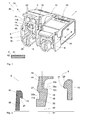
- FIG. 1 a perspective view of two designed as a print terminals 40 terminals 50.
- the terminal 50 has each have a housing 1, which consists here in the embodiment of a base body 2 and an actuating part 3.
- the actuating part 3 is received pivotably mounted at the rear end of the base body 2.
- Both print terminals 40 are constructed identically.
- two cable guides 43 are provided for connecting two cables 5 here.
- the diameter of the cable guides 43 is adapted to the diameter of the cable 5 to be connected.
- connection terminal 50 has cutting contacts 4 for contacting cables 5 to be connected.
- the cutting contacts 4 cut through the insulation 41 of FIG Cable 5, so that the cutting contacts 4 comes into contact with the conductor 42 via the individual wires.
- FIG. 1 shows the terminal 50 shown on the left the opening position 6, while the further right drawn terminal 50 represents the contact position 7.
- a first latching device 8 ensures a secure latching of the housing 1 in the open position 6.
- the locking legs 14 and 15 engage with the latching arms 16 and 17 of the base body 2 and ensure that the housing can not be opened further.
- the housing can be transferred with a defined but relatively small force again from the open position 6 in the contact position 7.
- Fig. 1 it can be seen, in the two illustrated print terminals 40, the operating parts 3 are provided in each case by pivoting axes arranged horizontally in the interior of the main body 2.
- the pivoting levels 46, within which the actuating parts 3 pivot, are arranged perpendicular to the pivot axis 47.
- FIG. 2 shows a schematic view of the locking elements 11a and 12a of the first and second locking means 8 and 9.
- a Detent leg 14 shown In the middle of the figure is a Detent leg 14 shown, which is connected to the actuating part 3.
- FIG. 2 is purely schematically shown a pivot axis 47 about which the actuating part 3 is provided with the latching leg 14 disposed thereon pivotally.
- a pivoting plane 46 within which the locking leg 14 is provided pivotable about the pivot axis, is also shown. In addition to the marked pivoting plane 46, all the planes parallel to it are also pivoting planes through the actuating part 3.
- the latching element 11a is arranged on a longitudinal side 44 of the latching limb 14.
- the locking element 11b is provided on an opposite longitudinal side 44 of the locking leg 14.
- the locking elements 11a and 11b are arranged transversely and here even perpendicular to the pivot plane 46.
- the latching elements 11a and 11b therefore extend in their effective direction here approximately parallel to the pivot axis.
- Links of the locking leg 14 is designed as a locking lug 20 locking part 20 at the end of the latching arm 16 is shown.
- An acute angle 25 is provided on the latching part 20 designed as a latching angle, which is for example in the range between 70 ° and 80 ° and which ensures a reliable and fixed latching of the housing 1 in the open position 6.
- the latching lug 20 of the latching arm 16 is intended to cooperate with the latching groove 22a of the latching limb 14.
- the latching groove 22a serves as a latching element 11a.
- the latching groove 22a has an obtuse angle 27 at the first end 24 located further up, which is between 100 and 130 ° here.
- an acute angle 25 is provided, which cooperates in particular with the acute angle 25 on the latching lug 20 of the latching arm 16.
- the angle 25 may also be 90 ° or even greater, to effect an automatic opening at high loads.
- the latching groove 22a forms, together with the latching lug 20 on the latching arm 16, the first latching device 8.
- the second and independent locking device 9 is formed by the rear handle 33a on the locking leg 14 and by the locking lug 31 on the locking lever 18.
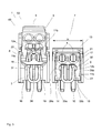
- FIG. 3 shows a front view of the two terminals 50 according to FIG. 1 with the left terminal 50 in the open position 6 and the right terminal 50 in the contact position 7th
- the latching part 20 of the latching arm 16 cooperates with the latching element 22a designed as latching element 11a of the spring leg 14 on the left half of the left connection terminal 50.
- the latching element 22a designed as latching element 11a of the spring leg 14 on the left half of the left connection terminal 50.
- Terminal 50 acts in the open position 6, designed as a locking lug 21 locking part of the latching arm 17 with the latching groove 22 b formed as latching element 11 b of the spring leg 15 together.
- Each terminal 50 is mirror-symmetrical in front view.
- the obtuse angle 27 at the other end of the locking grooves 22a and 22b allows the transfer of the operating part 3 from the opening position 6 to the contact position 7 with a relatively small force.
- the latching arms 16 and 17 elastically spring outward. This is made possible even with closely juxtaposed terminals 50, since the latching arms 16 and 17 slightly converge, so that an elastic springs is possible.
- the second latching device 9 In the contact position 7, the second latching device 9 is latched, the latching lugs 31 and 32 latching on the latching levers 18 and 19 of the main body 2 with the latching elements 29a and 29b designed as latching elements 12a and 12b of the first and second latching shanks 14 and 15.
- the locking grooves 29a and 29b are here designed as an underhand grips 33a and 33b, so that the latching lugs 31 and 32 designed latching parts 28 of the second latching device abut the rear handles 33a and 33b and thus lock the second latching device 9.
- the locking angle of the locking parts 28 can basically be arbitrary. Preferably, the angle is chosen so that an accidental opening is not possible.
- the locking lever 18 and 19 of the second locking device 9 by means of a tool as far as pressed against each other until the locking lever 18 and 19 on the support wall 38 between the locking levers 18 and 19th issue.
- the locking lever 18 and 19 can support and also excessive deformation is avoided, which could lead to breakage of the locking lever.
- each solder pins 10 are awarded, with which the terminal 50 is connected for example with a circuit board.
Landscapes
- Details Of Connecting Devices For Male And Female Coupling (AREA)
- Connections By Means Of Piercing Elements, Nuts, Or Screws (AREA)
- Package Frames And Binding Bands (AREA)
- Lock And Its Accessories (AREA)
- Connections Arranged To Contact A Plurality Of Conductors (AREA)
- Coupling Device And Connection With Printed Circuit (AREA)
- Clamps And Clips (AREA)
Abstract
Description
- Die vorliegende Erfindung betrifft eine Anschlussklemme mit einem Gehäuse und einem Schneidkontakt zum Anschluss eines Kabels. Dabei besteht das Gehäuse wenigstens aus einem Grundkörper und einem damit verrastbaren Betätigungsteil, welches schwenkbar an dem Grundkörper aufgenommen ist.
- Im Stand der Technik sind verschiedenste Anschlussklemmen mit einem Schneidkontakt bekannt geworden, bei denen ein Kabel eingeführt und nach dem Schließen des Gehäuses das Kabel von einem Schneidkontakt elektrisch leitend kontaktiert wird.
- Um die Handhabung zu vereinfachen, sind Gehäuse bekannt geworden, die in der Kontaktposition verrasten und somit den hergestellten Kontakt sichern. Solche Ausführungsformen funktionieren zuverlässig und erlauben einen dauerhaft sicheren Betrieb. Nachteilig an solchen Anschlussklemmen ist allerdings, dass zum Herstellen des Kontakts das Gehäuse beispielsweise mit einer Hand geöffnet werden muss und anschließend mit der anderen Hand ein anzuschließendes Kabel eingeführt werden muss. Das bedeutet, dass regelmäßig eine Zweihandbedienung erforderlich ist.
- Mit der
FR 2 730 096 A1 - Mit der
US 6,254,421 B1 ist eine Anschlusseinrichtung bekannt geworden, die dazu geeignet ist, einen isolierten Leiter mit einem Schneidkontakt zu kontaktieren. An dem Gehäuse ist ein Deckel mit einer Kabelführung schwenkbar vorgesehen und an dem Gehäuse sind zwei Rastarme vorgesehen, die mit Rastvorsprüngen an dem schwenkbaren Deckel zusammenwirken, so dass der Deckel in der offenen Position rastend an dem Rastarm gehalten wird. In der geschlossenen Position rastet der Rastarm an anderen Rastvorsprüngen des Deckels, um den geschlossenen Kontaktzustand zu sichern. - Das System gemäß der
US 6,254,421 B1 ermöglicht ein leichtes Einführen eines anzuschließenden Kabels, da das Gehäuse ebenfalls nicht nur im geschlossenen, sondern auch im offenen Zustand über den Rastarm fixiert wird. Vorteilhaft ist außerdem, dass der Abstand der Rastmittel von der Schwenkachse groß ist. Nachteilig ist allerdings die relativ große Kraft, die überwunden werden muss, um die Anschlussklemme von dem verrasteten Öffnungszustand in den verrasteten Klemmzustand zu überführen. Insbesondere bei modernen Lötprozessen, bei denen solche Anschlussklemmen in einem Reflow-Prozess mitaufgelötet werden, treten hohe Temperaturen auf, bei denen nur hochtemperaturfeste Kunststoffe einsetzbar sind. Solche hochtemperaturfesten Kunststoffe sind relativ spröde, so dass bei der Anschlussklemme im Öffnungszustand die erhebliche Gefahr besteht, dass Rastelemente abbrechen und somit das gesamte Bauteil nicht mehr brauchbar ist. - Ein weiterer Nachteil dem System gemäß der
US 6,254,421 B1 ist, dass die Kraft der Verrastung von der Fertigungstoleranz der Bauteile abhängt. Wird die Schwenkachse zudem noch mit Spiel in dem Gehäuse aufgenommen, so hängt die benötigte Kraft zum Öffnen oder Schließen stark von dem tatsächlich vorliegenden Spiel und der Fertigungstoleranz ab. Eine separate Einstellung der benötigten Kraft, um den Deckel auf- und zu zuschwenken, ist deshalb nicht möglich. - Es ist deshalb die Aufgabe der vorliegenden Erfindung eine Anschlussklemme mit einem schwenkbaren Betätigungsteil zur Verfügung zu stellen, bei welcher eine Verrastung in einem geöffneten und in einem geschlossenen Zustand möglich ist, wobei die benötigten Kräfte zum Öffnen oder Schließen konstruktiv unabhängig voneinander einstellbar sind.
- Diese Aufgabe wird gelöst durch eine Anschlussklemme mit den Merkmalen des Anspruchs 1. Bevorzugte Weiterbildungen der Erfindung sind Gegenstand der Unteransprüche. Weitere Vorteile und Merkmale der Erfindung ergeben sich aus dem Ausführungsbeispiel.
- Die erfindungsgemäße Anschlussklemme umfasst wenigstens ein Gehäuse mit wenigstens einem Grundkörper und wenigstens einem schwenkbar daran aufgenommenem Betätigungsteil. Wenigstens ein Schneidkontakt ist zum Anschluss eines Kabels vorgesehen. Dabei ist das Betätigungsteil sowohl in einer Öffnungsposition als auch in einer Kontaktposition mit dem Grundkörper verrastbar vorgesehen. Wenigstens ein Rastschenkel ist an dem Betätigungsteil vorgesehen. Der Rastschenkel weist an einer Längsseite quer zu der Schwenkebene wenigstens ein erstes Rastelement auf, um das Betätigungsteil mit dem Grundkörper in der Öffnungsposition zu verrasten. Der oder wenigstens ein Rastschenkel umfasst an dem Betätigungsteil an einer anderen Längsseite wenigstens ein zweites Rastelement, um das Betätigungsteil mit dem Grundkörper in der Kontaktposition zu verrasten. Das zweite Rastelement ist ebenfalls quer zu der Schwenkebene angeordnet.
- Die erfindungsgemäße Anschlussklemme hat viele Vorteile, da es durch die Anordnung des ersten und des zweiten Rastelementes an den Längsseiten quer zu der Schwenkebene ermöglicht wird, die Verrastungskraft unabhängig von der Fertigungstoleranz oder einem möglichen Spiel zwischen der Schwenkachse und dem verschwenkbaren Betätigungsteil vorzusehen. Liegt ein größeres Spiel an der Schwenkachse vor, so wird das Rastelement in radialer Richtung etwas versetzt. Das führt aber zu praktisch keiner Änderung der auftretenden Kräfte, da der Eingriffszustand des Rastelementes davon nicht beeinflusst wird. Eine Erhöhung oder auch eine Verringerung der Verrastungskraft tritt nicht auf. Das erste und das zweite Rastelement sind vorzugsweise etwa entlang der bzw. parallel zu der Schwenkachse ausgerichtet.
- Ein weiterer Vorteil ist, dass die Verrastungskräfte unabhängig voneinander ausgelegt werden können. Die Verrastungskraft in der geschlossenen Kontaktposition kann größer gewählt werden als die Verrastungskraft in der Öffnungsposition und umgekehrt. Die Kräfte hängen nicht von Fertigungstoleranz oder einem gegebenenfalls vorgesehenen Spiel ab, sondern können konstruktiv fest und unabhängig voneinander vorgegeben werden.
- Das erste Rastelement ist insbesondere Teil einer ersten Rasteinrichtung, die wenigstens bewirkt, dass der Grundkörper und das Betätigungsteil im geöffneten Zustand miteinander verrastet werden. Das zweite Rastelement ist insbesondere Teil einer zweiten Rasteinrichtung, die wenigstens bewirkt, dass der Grundkörper und das Betätigungsteil in dem geschlossenen Zustand verrastet werden können.
- Durch die erste und die zweite Rasteinrichtung wird eine einfache Bedienung der Anschlussklemme ermöglicht. Die Kraft zur Überführung des Betätigungsteils von der Öffnungsposition in die Kontaktposition kann erheblich geringer gewählt werden, als die Kraft, die nötig ist, um das Betätigungsteil aus der Kontaktposition wieder in die Öffnungsposition zu überführen. Dadurch, dass beide Kräfte unabhängig voneinander gewählt werden können, da zwei unabhängige Rasteinrichtungen vorgesehen sind, kann das System optimal auf den eingesetzten Werkstoff ausgerichtet werden. Besteht das Gehäuse beispielsweise aus einem spröden Kunststoff, kann die notwendige Kraft zur Überführung des Betätigungsteils von der Öffnungsposition in die Kontaktposition entsprechend geringer gewählt werden, um Schädigungen des Betätigungsteils und/oder des Grundkörpers weitestgehend zu vermeiden.
- Die Erfindung ermöglicht es weiterhin, dass die Anschlussklemme in der Öffnungsposition verrastet und praktisch nicht weiter zu öffnen ist, auch wenn erhebliche Kräfte eingesetzt werden. Im Unterschied dazu wird es mit einer relativ leichten Kraft ermöglicht, dass Betätigungsteil aus der Öffnungsposition in die Kontaktposition zu überführen. Diese Kraft kann aber über eine Mehrzahl und sogar Vielzahl von Öffnungs- und Schließvorgängen im Wesentlichen konstant gehalten werden, da kein oder nur ein geringer Verschleiß auftritt. Durch die voneinander unabhängigen ersten und zweiten Rasteinrichtungen können alle Parameter frei gewählt werden.
- Vorzugsweise ist an einem Betätigungsteil wenigstens eine Kabelführung vorgesehen, um eine definierte Überführung eines eingeführten Kabels zu dem Schneidkontakt zu gewährleisten.
- Der Schneidkontakt ermöglicht den Anschluss eines Kabels mit einem isolierten Leiter.
- Vorzugsweise ist das Betätigungsteil als Gehäusedeckel ausgeführt, so dass das Gehäuse nach der Überführung des Betätigungsteils von der Öffnungsposition in die Kontaktposition praktisch geschlossen ist.
- Besonders bevorzugt ragt wenigstens ein Rastschenkel von dem Betätigungsteil aus in Richtung des Grundkörpers. Vorzugsweise sind wenigstens zwei Rastschenkel vorgesehen. Zwei Rastschenkel ermöglichen eine symmetrische und damit besonders sichere und zuverlässige Verbindung.
- Vorteilhafterweise sind an dem Grundkörper wenigstens ein Rastarm und wenigstens ein Rasthebel vorgesehen.
- Besonders bevorzugt weist die erste Rasteinrichtung miteinander zusammenwirkende Rastelemente an dem Rastschenkel und Rastteile an dem Rastarm auf. Dabei ist insbesondere wenigstens ein Rastelement und/oder wenigstens ein Rastteil als Rastnase und wenigstens ein Rastelement und/oder wenigstens ein Rastteil als Rastnut ausgeführt. Es ist möglich, dass eine Rastnase als erstes Rastelement an dem Rastschenkel vorgesehen ist, während eine Rastnut an dem Rastarm vorgesehen ist. Möglich und bevorzugt ist es aber auch, dass an dem Rastschenkel eine Rastnut als erstes Rastelement vorgesehen ist und dass an dem Rastarm eine Rastnase vorgesehen ist.
- Die Rastnut weist auf einer Seite bzw. an einem Ende vorzugsweise einen spitzen Winkel auf und die Rastnut weist auf der anderen Seite bzw. an dem anderen Ende vorzugsweise einen stumpfen Winkel auf. Der stumpfe Winkel sorgt dafür, dass die zur Überwindung der Rasteinrichtung benötigte Kraft relativ gering ist. Der spitze Winkel hingegen bewirkt, dass bei zunehmender Kraft die Verrastung noch stärker wird, so dass ohne weitere Hilfsmittel eine Öffnung nicht möglich ist, ohne die Rasteinrichtung zu zerstören.
- An der zweiten Rasteinrichtung sind auch miteinander zusammenwirkende Rastelemente und Rastteile vorgesehen, die an dem Rastschenkel und an dem Rasthebel angeordnet sind. Dabei ist wenigstens ein Rastelement als Rastnut und wenigstens ein Rastteil als Rastnase ausgeführt. Es ist möglich, dass die Rastnut an dem Rasthebel und dass die Rastnase als zweites Rastelement an dem Rastschenkel vorgesehen sind. Es ist auch möglich, dass die Rastnut als zweites Rastelement an dem Rastschenkel vorgesehen ist und dass an dem Rasthebel eine Rastnase vorgesehen ist. Jedenfalls wird durch das Zusammenwirken der Rastnut mit der Rastnase eine zuverlässige Verrastung des Gehäuses in der Kontaktposition bewirkt. Der Rastwinkel bei der Verrastung der Rastelemente kann jedenfalls spitz ausgeführt sein, um ein Überführen in die Öffnungsposition auch bei Einsatz größerer Kräfte nicht zu ermöglichen.
- Es ist möglich, dass die Rastnut als Hintergriff ausgeführt ist, so dass die damit zusammenwirkende Rastnase an dem Hintergriff einrastet und den Grundkörper oder das Betätigungsteil hintergreift.
- In allen Ausgestaltungen ist es bevorzugt, dass an dem Betätigungsteil wenigstens ein Sichtfenster vorgesehen ist. Vorzugsweise ist das Sichtfenster am hinteren Anschlag oder in der Nähe des hinteren Anschlags vorgesehen. Ein solches Sichtfenster ist sehr vorteilhaft, da durch einen einfachen Blick überprüfbar ist, ob ein eingeschobenes Kabel weit genug eingeschoben wurde. Ist das eingeschobene Kabel an dem Sichtfenster noch nicht sichtbar, muss es weiter eingeschoben werden und wenn es dort sichtbar ist, kann das Betätigungsteil betätigt werden, um das Kabel an dem Schneidkontakt zu kontaktieren. Dazu ist es bevorzugt, dass der Abstand des Sichtfensters von dem Schneidkontakt so bemessen ist, dass wenn ein Kabel an dem Sichtfenster sichtbar ist, ein zuverlässiger Kontakt an dem Schneidkontakt möglich ist.
- In allen Ausgestaltungen ist es besonders bevorzugt, dass der Grundkörper und/oder das Betätigungsteil wenigstens teilweise aus einem hochtemperaturfesten Kunststoff bestehen. Eine solche Ausgestaltung ermöglicht einen zuverlässigen Einsatz solcher Anschlussklemmen und die Vormontage auf Leiterplatten und dergleichen, auch wenn ein Reflow-Lötprozess eingesetzt wird. Hochtemperaturfeste Kunststoffe sind nicht transparent, so dass ein Sichtfenster die Kontrolle über ein eingeschobenes Kabel ermöglicht.
- Vorzugsweise sind an dem Grundkörper symmetrisch zwei Rastarme vorgesehen, deren Abstand sich nach oben hin verjüngt. Das bedeutet, dass auch bei dicht nebeneinander angeordneten Anschlussklemmen die Rastarme im Bereich der Rastnasen auseinander schwenken können, um einen Verrastungszustand zu überwinden.
- Vorzugsweise sind zwei Rasthebel vorgesehen, die insbesondere symmetrisch an einem zentralen Bereich des Grundkörpers angeordnet sind. Durch eine elastische Verformung der Rasthebel mittels beispielsweise eines Werkzeugs kann der Rastzustand der zweiten Rasteinrichtung in der Kontaktposition aufgehoben werden und das Gehäuse wieder geöffnet werden.
- Besonders bevorzugt sind in der Kontaktposition die beiden Rasthebel zwischen den beiden Rastschenkeln vorgesehen. Die zwei Rastschenkel sind in der Kontaktposition zwischen den beiden Rastarmen angeordnet. Dadurch wird ein einfacher und kompakter Aufbau ermöglicht, der eine zuverlässige Funktion bei geringen Bedienkräften ermöglicht. Eine solche Ausgestaltung ist besonders bevorzugt und erlaubt einen z. B. spiegelsymmetrischen Aufbau.
- An jedem Rastschenkel ist ein erstes Rastelement vorgesehen. Die ersten Rastelemente sind dann vorzugsweise an den jeweils äußeren Längsseiten der Rastschenkel angeordnet, die voneinander wegweisen. Die ersten und hier äußeren Rastelemente sind in der Öffnungsposition im Rastzustand mit den nach innen ragenden Rastnasen der Rastarme. Dabei können die ersten Rastelemente als Rastnuten vorgesehen sein, in die von außen Rastnasen der Rastarme eingreifen.
- An jedem Rastschenkel ist weiterhin wenigstens ein zweites Rastelement vorgesehen. Die zweiten Rastelemente sind vorzugsweise an den jeweils inneren Längsseiten der Rastschenkel angeordnet, die aufeinander zu zeigen. Die zweiten und hier inneren Rastelemente sind in der Kontaktposition im Rastzustand mit den nach außen ragenden Rastnasen der Rasthebel. Dabei können die zweiten Rastelemente als Rastnuten vorgesehen sein, in die von innen Rastnasen der Rasthebel eingreifen.
- Zum Öffnen werden die beiden Rasthebel aufeinander zu gedrückt. Um eine Überlastung oder zu starke Verformung der Rathebel zu verhindern, kann zwischen den beiden Rasthebeln eine Stützwand vorgesehen sein, die beim Öffnen mit einem Werkzeug einen definierten Anschlag zur Verfügung stellt. Die Stützwand begrenzt die mögliche Verformung der Rasthebel und sichert so dauerhaft den zuverlässigen Betrieb der Anschlussklemme. In einer solchen Ausgestaltung haben die beiden Rasthebel mit der dazwischen vorgesehenen Stützwand eine etwa W-förmige Struktur.
- Es ist besonders bevorzugt, wenn die beiden Rasthebel nach vorn überstehen. Das ermöglicht einer Bedienperson das einfache Ergreifen der Rasthebel mit einem Werkzeug, wie beispielsweise einer Zange, um die Rasthebel aufeinander zuzudrücken und somit die Verrastung der zweiten Rasteinrichtung zu überwinden. Im Anschluss daran kann das Betätigungsteil nach oben verschwenkt werden, wodurch das kontaktierte Kabel wieder freigegeben wird.
- Gegebenenfalls kann zum Verstellen des Gehäuses auch eine Bedienung per Hand möglich sein.
- Häufig werden Anschlussklemmen mit zwei Kabelanschlüssen zur Verfügung gestellt, bei denen dann zwei Schneidkontakte zur Kontaktierung der beiden anzuschließenden Kabel vorgesehen sind. Um die erforderlichen Sicherheitsabstände zwischen den Schneidkontakten zu gewährleisten, sind die Schneidkontakte insbesondere in Längsrichtung des Gehäuses versetzt zueinander angeordnet. Damit wird der Abstand zwischen den Schneidkontakten und somit die Kriechstrecke vergrößert, so dass trotz mehrerer paralleler Kabel eine unzulässige Verkleinerung der Luft- und Kriechstrecken nicht erfolgt.
- Weitere Vorteile und Merkmale der vorliegenden Erfindung ergeben sich aus dem Ausführungsbeispiel, welches im Folgenden mit Bezug auf die beiliegenden Figuren erläutert wird:
- Darin zeigen:
- Fig. 1
- eine schematische perspektivische Ansicht zweier Anschlussklemmen;
- Fig. 2
- die Querschnitte eines Rastarms,eines Rasthebels und eines Rastschenkels;
- Fig. 3
- eine Vorderansicht der beiden Anschlussklemmen gemäß
Figur 1 . - Mit Bezug auf die
Figuren 1-3 wird ein Ausführungsbeispiel der vorliegenden Erfindung erläutert. Darin zeigtFigur 1 eine perspektivische Darstellung zweier als Printklemmen 40 ausgeführten Anschlussklemmen 50. Die Anschlussklemme 50 verfügt jeweils über ein Gehäuse 1, welches hier im Ausführungsbeispiel aus einem Grundkörper 2 und einem Betätigungsteil 3 besteht. Das Betätigungsteil 3 ist am hinteren Ende des Grundkörpers 2 schwenkbar gelagert aufgenommen. Beide Printklemmen 40 sind identisch aufgebaut. - An dem Betätigungsteil 3 sind hier zwei Kabelführungen 43 zum Anschluss zweier Kabel 5 vorgesehen. Dabei ist der Durchmesser der Kabelführungen 43 an den Durchmesser der anzuschließenden Kabel 5 angepasst.
- Die Anschlussklemme 50 verfügt über Schneidkontakte 4 zur Kontaktierung anzuschließender Kabel 5. Bei der Kontaktierung schneiden die Schneidkontakte 4 durch die Isolierung 41 des Kabels 5, so dass die Schneidkontakte 4 in Kontakt mit dem Leiter 42 über dessen einzelnen Adern gelangt.
- In
Figur 1 zeigt die links abgebildete Anschlussklemme 50 die Öffnungsposition 6, während die weiter rechts eingezeichnete Anschlussklemme 50 die Kontaktposition 7 darstellt. - Eine erste Rasteinrichtung 8 sorgt für eine sichere Verrastung des Gehäuses 1 in der Öffnungsposition 6. In dieser Öffnungsposition 6 verrasten die Rastschenkel 14 und 15 mit den Rastarmen 16 und 17 des Grundkörpers 2 und sorgen dafür, dass das Gehäuse nicht weiter geöffnet werden kann. Außerdem wird sicher gestellt, dass das Gehäuse mit einer definierten aber relativ geringen Kraft wieder von der Öffnungsposition 6 in die Kontaktposition 7 überführt werden kann.
- Am hinteren Ende des Gehäuses 1 ist in dem Gehäusedeckel 13 wenigstens ein Sichtfenster 35 vorgesehen, welches die Überprüfung erlaubt, ob ein anzuschließendes Kabel 5 weit genug eingeschoben ist. Ist das Kabel 5 noch nicht weit genug eingeschoben und in dem Sichtfenster 35 nicht sichtbar, muss das Kabel 5 entlang der Längsrichtung 39 der Anschlussklemme 50 weiter eingeführt werden.
- Wie aus
Fig. 1 ersichtlich, sind bei den beiden dargestellten Printklemmen 40 die Betätigungsteile 3 jeweils um hier horizontal angeordnete Schwenkachsen im Inneren des Grundkörpers 2 schwenkbar vorgesehen. Die Schwenkebenen 46, innerhalb welcher die Betätigungsteile 3 verschwenken, sind senkrecht zu der Schwenkachse 47 angeordnet. -
Figur 2 zeigt in einer schematisierten Ansicht die Rastelemente 11a und 12a der ersten und der zweiten Rasteinrichtung 8 und 9. In der Mitte der Figur ist ein Rastschenkel 14 abgebildet, der mit dem Betätigungsteil 3 verbunden ist. - In
Figur 2 ist rein schematisch eine Schwenkachse 47 eingezeichnet, um welche das Betätigungsteil 3 mit dem daran angeordneten Rastschenkel 14 verschwenkbar vorgesehen ist. Eine Schwenkebene 46, innerhalb derer der Rastschenkel 14 um die Schwenkachse verschwenkbar vorgesehen ist, ist ebenfalls eingezeichnet. Neben der eingezeichneten Schwenkebene 46 sind auch alle dazu parallelen Ebenen durch das Betätigungsteil 3 Schwenkebenen. - Das Rastelement 11a ist auf einer Längsseite 44 des Rastschenkels 14 angeordnet. Das Rastelement 11b ist auf einer gegenüberliegenden Längsseite 44 des Rastschenkels 14 vorgesehen. Die Rastelemente 11a und 11b sind quer und hier sogar senkrecht zu der Schwenkebene 46 angeordnet. Die Rastelemente 11a und 11b erstrecken sich deshalb in ihrer Wirkrichtung hier etwa parallel zu der Schwenkachse. Dadurch werden die Wirkweise und die Stärke der Wirkung der jeweiligen Verrastung unabhängig von der Fertigungstoleranz der Schwenkachse und deren Lagerung, denn eine geringe Verringerung oder Vergrößerung des Schwenkradius ändert die jeweilige Verrastungskraft der Rastelemente 11a und 11b nicht.
- Auch ein etwaiges Spiel bei der Lagerung der Schwenkachse hat keine Auswirkung auf die Verrastungstärke. Durch diese konstruktive Gestaltung kann die Verrastungstärke auf die gewünschten Anforderungen eingestellt werden. Außerdem wird eine separate und unabhängige Verrastungstärke der beiden Rasteinrichtungen 8 und 9 ermöglicht.
- Links von dem Rastschenkel 14 ist ein als Rastnase 20 ausgeführtes Rastteil 20 am Ende des Rastarms 16 abgebildet.
- An dem als Rastnase 20 ausgebildeten Rastteil ist ein spitzer Winkel 25 vorgesehen, der beispielsweise im Bereich zwischen 70° und 80° liegt und der eine zuverlässige und feste Verrastung des Gehäuses 1 in der Öffnungsposition 6 gewährleistet.
- Die Rastnase 20 des Rastarms 16 ist dafür vorgesehen, mit der Rastnut 22a des Rastschenkels 14 zusammenzuwirken. Die Rastnut 22a dient als Rastelement 11a. Die Rastnut 22a weist an dem sich weiter oben befindenden ersten Ende 24 einen stumpfen Winkel 27 auf, der hier zwischen 100 und 130° beträgt. An dem anderen, tieferen Ende 26 ist hier hingegen ein spitzer Winkel 25 vorgesehen, der insbesondere mit dem spitzen Winkel 25 an der Rastnase 20 des Rastarms 16 zusammenwirkt. Der Winkel 25 kann auch 90° oder sogar größer sein, um bei großen Belastungen ein selbsttätiges Öffnen zu bewirken.
- Die Rastnut 22a bildet zusammen mit der Rastnase 20 an dem Rastarm 16 die erste Rasteinrichtung 8.
- Die zweite und davon unabhängige Rasteinrichtung 9 wird durch den Hintergriff 33a an dem Rastschenkel 14 und durch die Rastnase 31 an dem Rasthebel 18 gebildet.
-
Figur 3 zeigt eine Vorderansicht der zwei Anschlussklemmen 50 gemäßFigur 1 mit der linken Anschlussklemme 50 in der Öffnungsposition 6 und der rechten Anschlussklemme 50 in der Kontaktposition 7. - Klar erkennbar ist, dass in der Öffnungsposition 6 das als Rastnase 20 ausgebildete Rastteil des Rastarms 16 mit dem als Rastnut 22a ausgebildeten Rastelement 11a des Federschenkels 14 an der linken Hälfte der linken Anschlussklemme 50 zusammenwirkt. Auf der rechten Seite der linken
- Anschlussklemme 50 wirkt in der Öffnungsposition 6 das als Rastnase 21 ausgebildete Rastteil des Rastarms 17 mit dem als Rastnut 22b ausgebildeten Rastelement 11b des Federschenkels 15 zusammen. Jede Anschlussklemme 50 ist in der Vorderansicht spiegelsymmetrisch aufgebaut.
- Dadurch, dass hier der spitze Winkel 25 an den Rastelementen 11a und 11b und den Rastnasen 20 und 21 der ersten Rasteinrichtung 8 vorgesehen ist, wird ein zu weites Öffnen der Anschlussklemme 50 zuverlässig verhindert. Der stumpfe Winkel 27 an dem anderen Ende der Rastnuten 22a und 22b erlaubt das Überführen des Betätigungsteils 3 von der Öffnungsposition 6 in die Kontaktposition 7 mit einer relativ geringen Kraft. Bei der Überführung federn die Rastarme 16 und 17 elastisch nach außen. Das wird auch bei eng nebeneinander angeordneten Anschlussklemmen 50 ermöglicht, da die Rastarme 16 und 17 leicht aufeinander zulaufen, sodass ein elastisches Federn ermöglicht wird.
- In der Kontaktposition 7 verrastet die zweite Rasteinrichtung 9, wobei die Rastnasen 31 und 32 an den Rasthebeln 18 und 19 des Grundkörpers 2 mit den als Rastnuten 29a und 29b ausgeführten Rastelementen 12a und 12b des ersten und zweiten Rastschenkels 14 und 15 verrasten. Die Rastnuten 29a und 29b sind hier als Hintergriffe 33a und 33b ausgeführt, sodass die als Rastnasen 31 und 32 ausgeführten Rastteile 28 der zweiten Rasteinrichtung an den Hintergriffen 33a und 33b anliegen und somit die zweite Rasteinrichtung 9 verrasten.
- Der Rastwinkel der Rastteile 28 kann grundsätzlich beliebig sein. Vorzugsweise wird der Winkel so gewählt, dass ein ungewolltes Öffnen nicht möglich ist.
- Zum Öffnen und zum Überführen der Anschlussklemme 50 von der Kontaktposition 7 in die Öffnungsposition 6 können die Rasthebel 18 und 19 der zweiten Rasteinrichtung 9 mittels eines Werkzeugs soweit aufeinander zugedrückt werden, bis die Rasthebel 18 und 19 an der Stützwand 38 zwischen den Rasthebeln 18 und 19 anliegen. Dadurch können sich die Rasthebel 18 und 19 abstützen und außerdem wird eine zu starke Verformung vermieden, welche zu einem Bruch der Rasthebel führen könnte.
- An dem Gehäuse 1 sind jeweils Lötstifte 10 zuerkennen, mit denen die Anschlussklemme 50 beispielsweise mit einer Leiterplatte verbunden wird.
-
- 1
- Gehäuse
- 2
- Grundkörper
- 3
- Betätigungsteil
- 4
- Schneidkontakt
- 5
- Kabel
- 6
- Öffnungsposition
- 7
- Kontaktposition
- 8
- Erste Rasteinrichtung
- 9
- Zweite Rasteinrichtung
- 10
- Lötstift
- 11a, 11b
- Rastelement
- 12a, 12b
- Rastelement
- 13
- Gehäusedeckel
- 14, 15
- Rastschenkel
- 16, 17
- Rastarm
- 18, 19
- Rasthebel
- 20, 21
- Rastteil
- 22a,22b
- Rastnut
- 24
- Eine Seite
- 25
- Spitzer Winkel
- 26
- Andere Seite
- 27
- Stumpfer Winkel
- 28
- Rastteil
- 29, 30
- Rastglied
- 31a,31b
- Rastnase
- 33, 34
- Hintergriff
- 35
- Sichtfenster
- 36
- Abstand
- 37
- Zentraler Bereich
- 38
- Stützwand
- 39
- Längsrichtung
- 40
- Printklemme
- 41
- Isolierung
- 42
- Leiter
- 43
- Kabelführung
- 44,45
- Längsseite
- 46
- Schwenkebene
- 47
- Schwenkachse
- 50
- Anschlussklemme
Claims (15)
- Anschlussklemme (50) mit einem Gehäuse (1) mit wenigstens einem Grundkörper (2) und einem schwenkbar daran aufgenommenem Betätigungsteil (3) und wenigstens einem Schneidkontakt (4) zum Anschluss eines Kabels (5),
wobei das Betätigungsteil (3) in einer Öffnungsposition (6) und in einer Kontaktposition (7) mit dem Grundkörper (2) verrastbar vorgesehen ist,
dadurch gekennzeichnet,
dass wenigstens ein Rastschenkel (14, 15) an dem Betätigungsteil (3) vorgesehen ist, und dass der Rastschenkel (14, 15) an einer Längsseite (44) quer zu der Schwenkebene (46) wenigstens ein erstes Rastelement (11a, 11b) umfasst, um das Betätigungsteil (3) mit dem Grundkörper (2) in der Öffnungsposition (6) zu verrasten, und dass der Rastschenkel (14, 15) an dem Betätigungsteil (3) an einer anderen quer zu der Schwenkebene (46) angeordneten Längsseite (45) wenigstens ein zweites Rastelement (12a, 12b) umfasst, um das Betätigungsteil (3) mit dem Grundkörper (2) in der Kontaktposition (7) zu verrasten. - Anschlussklemme (50) nach Anspruch 1, wobei das erste Rastelement (11a, 11b) Teil einer ersten Rasteinrichtung (8) ist, die bewirkt, dass der Grundkörper (2) und das Betätigungsteil (3) in der Öffnungsposition (6) miteinander verrastbar sind,
und wobei das zweite Rastelement (12a, 12b) Teil einer zweiten Rasteinrichtung (9) ist, die bewirkt, dass der Grundkörper (2) und das Betätigungsteil (3) in der Kontaktposition (7) verrastbar sind. - Anschlussklemme (50) nach Anspruch 1 oder 2, wobei das Betätigungsteil (3) als Gehäusedeckel (13) ausgeführt ist, an welchem insbesondere ein Sichtfenster (35) und/oder wenigstens eine Kabelführung (43) vorgesehen ist.
- Anschlussklemme (50) nach einem der vorhergehenden Ansprüche, wobei die eine Längsseite (44) gegenüber der anderen Längsseite (45) vorgesehen ist.
- Anschlussklemme (50) nach einem der vorhergehenden Ansprüche, wobei an dem Grundkörper (2) wenigstens ein Rastarm (16, 17) und wenigstens ein Rasthebel (18, 19) vorgesehen sind.
- Anschlussklemme (50) nach einem der vorhergehenden Ansprüche 2 bis 4, wobei eine erste Rasteinrichtung (8) erste Rastelemente (11a, 11b) an dem Rastschenkel (14, 15) und Rastteile (20, 21) an dem Rastarm (16, 17) umfasst, wobei insbesondere wenigstens ein erstes Rastelement (11a, 11b) als Rastnut (22a, 22b) und wenigstens ein Rastteil (20, 21) als Rastnase (20, 21) ausgeführt ist.
- Anschlussklemme (50) nach dem vorhergehenden Anspruch, wobei die Rastnut (22a, 22b) auf einer Seite (24) einen spitzen Winkel (25) und auf der anderen Seite (26) einen stumpfen Winkel (27) aufweist.
- Anschlussklemme (50) nach einem der vorhergehenden Ansprüche 2 bis 7, wobei die zweite Rasteinrichtung (9) miteinander zusammenwirkende zweite Rastelemente (12a, 12b) an dem Rastschenkel (14, 15) und Rastteile an dem Rasthebel (18, 19) umfasst, wobei wenigstens ein Rastelement (28) als Rastnut (29, 30) und wenigstens ein Rastelement (28) als Rastnase (31, 32) ausgeführt ist.
- Anschlussklemme (50) nach einem der vorhergehenden Ansprüche, wobei wenigstens der Grundkörper (2) und/oder das Betätigungsteil (3) aus einem hochtemperaturfesten Kunststoff besteht.
- Anschlussklemme (50) nach einem der vorhergehenden Ansprüche, wobei zwei Rastarme (16, 17) symmetrisch an dem Grundkörper (2) vorgesehen sind, deren Abstand (36) sich nach oben hin verjüngt.
- Anschlussklemme (50) nach einem der vorhergehenden Ansprüche, wobei zwei Rasthebel (18, 19) symmetrisch an einem zentralen Bereich (37) des Grundkörpers (2) vorgesehen sind, zwischen denen eine Stützwand (38) vorgesehen ist.
- Anschlussklemme (50) nach dem vorhergehenden Anspruch, wobei im geschlossenen Zustand (11) die beiden Rasthebel (18, 19) zwischen den beiden Rastschenkeln (14, 15) vorgesehen sind, während die zwei Rastschenkel (14, 15) zwischen den beiden Rastarmen (16, 17) angeordnet sind.
- Anschlussklemme (50) nach einem der beiden vorhergehenden Ansprüche, wobei die beiden Rasthebel (18, 19) gegeneinander und insbesondere gegen die Stützwand (38) drückbar sind, um die zweite Rasteinrichtung (9) zu öffnen.
- Anschlussklemme (50) nach einem der drei vorhergehenden Ansprüche, wobei die beiden Rasthebel (18, 19) nach vorn überstehen.
- Anschlussklemme (50) nach einem der vorhergehenden Ansprüche, wobei wenigstens zwei Schneidkontakte (4) zur Kontaktierung zweier Kabel vorgesehen sind, wobei die Schneidkontakte (4) in Längsrichtung (39) versetzt angeordnet sind.
Applications Claiming Priority (1)
| Application Number | Priority Date | Filing Date | Title |
|---|---|---|---|
| DE102010047458A DE102010047458A1 (de) | 2010-10-06 | 2010-10-06 | Anschlussklemme |
Publications (3)
| Publication Number | Publication Date |
|---|---|
| EP2439814A2 true EP2439814A2 (de) | 2012-04-11 |
| EP2439814A3 EP2439814A3 (de) | 2013-05-29 |
| EP2439814B1 EP2439814B1 (de) | 2014-12-10 |
Family
ID=44759374
Family Applications (1)
| Application Number | Title | Priority Date | Filing Date |
|---|---|---|---|
| EP11008007.4A Active EP2439814B1 (de) | 2010-10-06 | 2011-10-04 | Anschlussklemme |
Country Status (7)
| Country | Link |
|---|---|
| US (1) | US8636537B2 (de) |
| EP (1) | EP2439814B1 (de) |
| JP (1) | JP5871545B2 (de) |
| CN (1) | CN102570171B (de) |
| DE (1) | DE102010047458A1 (de) |
| DK (1) | DK2439814T3 (de) |
| ES (1) | ES2530071T3 (de) |
Families Citing this family (6)
| Publication number | Priority date | Publication date | Assignee | Title |
|---|---|---|---|---|
| US9004937B2 (en) * | 2012-08-30 | 2015-04-14 | Zierick Manufacturing Corporation | Surface mount/through-hole crimp piercing zipcord connector |
| US9184515B1 (en) * | 2012-09-28 | 2015-11-10 | Anthony Freakes | Terminal blocks for printed circuit boards |
| DE102013012251A1 (de) * | 2013-07-24 | 2015-01-29 | Erni Production Gmbh & Co. Kg | Terminal zur Kontaktierung eines elektrischen Leiters |
| JP2020119689A (ja) * | 2019-01-22 | 2020-08-06 | 株式会社ヨコオ | コネクタ |
| DE102019113788A1 (de) * | 2019-05-23 | 2020-11-26 | Phoenix Contact Gmbh & Co. Kg | Baugruppe mit einem Lötstift und einer Lötstelle |
| JP2023008202A (ja) * | 2021-07-05 | 2023-01-19 | 株式会社アドバンテスト | 電子部品ハンドリング装置用のキャリアのコア、及び、キャリア、並びに、コアの取外方法 |
Citations (2)
| Publication number | Priority date | Publication date | Assignee | Title |
|---|---|---|---|---|
| FR2730096A1 (fr) | 1995-01-30 | 1996-08-02 | Seifel Sa | Dispositif de connexion pour constituer un noeud d'un reseau numerique, tel qu'un reseau de releve de compteurs electriques |
| US6254421B1 (en) | 1998-06-29 | 2001-07-03 | The Whitaker Corporation | Connector assembly having pivoting wire carrier with position detents |
Family Cites Families (18)
| Publication number | Priority date | Publication date | Assignee | Title |
|---|---|---|---|---|
| US4344664A (en) * | 1980-10-03 | 1982-08-17 | Ark-Les Corporation | Wide compliance insulation displacement terminal block |
| JP2575030Y2 (ja) * | 1991-09-30 | 1998-06-25 | 矢崎総業株式会社 | 圧接コネクタ |
| US5779497A (en) * | 1996-10-28 | 1998-07-14 | Leviton Manufacturing Co., Inc. | Quick wire electrical socket |
| JP4067181B2 (ja) * | 1998-06-15 | 2008-03-26 | スリーエム カンパニー | 圧接結線用コネクタとその圧接方法 |
| US6231373B1 (en) * | 1998-12-21 | 2001-05-15 | Avaya Technology Corp. | Connector with integrated living hinge and resettable spring |
| US6152760A (en) * | 1999-03-23 | 2000-11-28 | The Whitaker Corporation | Pivoting wire carrier for aerial drop wire and terminal therefor |
| DK174636B1 (da) * | 1999-12-30 | 2003-08-04 | Lk As | Termineringsanordning f.eks. til et multistik |
| US6296515B1 (en) * | 2000-02-29 | 2001-10-02 | Avaya Technology Corp. | Connector having a latching mechanism |
| US6406324B1 (en) * | 2001-03-13 | 2002-06-18 | Tyco Electronics Corporation | Insulation displacement connector terminal block |
| CN2503600Y (zh) * | 2001-07-24 | 2002-07-31 | 烟台开发区科达电子设备有限公司 | 带指示信号的塑壳断路器 |
| US6875043B2 (en) * | 2002-03-06 | 2005-04-05 | Illinois Tool Works, Inc. | Electrical component terminal connector |
| JP3119725U (ja) * | 2005-12-16 | 2006-03-09 | 株式会社渡辺製作所 | 圧接コネクタ |
| DE502006007551D1 (de) * | 2006-12-19 | 2010-09-09 | Siemens Ag | Schneidklemmen-Anschlusseinrichtung |
| US7867013B2 (en) * | 2008-08-04 | 2011-01-11 | 3M Innovative Properties Company | In-line splice connector |
| US7794267B2 (en) * | 2008-08-06 | 2010-09-14 | Tyco Electronics Corporation | Card edge connector with IDC wire termination |
| US7985094B2 (en) * | 2008-09-15 | 2011-07-26 | Adc Gmbh | Connector block |
| KR101026503B1 (ko) * | 2009-09-17 | 2011-04-05 | 이영환 | 전선 이음 커넥터 |
| US7845968B1 (en) * | 2010-01-12 | 2010-12-07 | Phoenix Contact Development & Manufacturing, Inc. | Electrical connector assembly and method |
-
2010
- 2010-10-06 DE DE102010047458A patent/DE102010047458A1/de not_active Withdrawn
-
2011
- 2011-09-30 CN CN201110303325.3A patent/CN102570171B/zh active Active
- 2011-09-30 JP JP2011216253A patent/JP5871545B2/ja not_active Expired - Fee Related
- 2011-10-04 DK DK11008007T patent/DK2439814T3/da active
- 2011-10-04 ES ES11008007.4T patent/ES2530071T3/es active Active
- 2011-10-04 EP EP11008007.4A patent/EP2439814B1/de active Active
- 2011-10-05 US US13/253,086 patent/US8636537B2/en not_active Expired - Fee Related
Patent Citations (2)
| Publication number | Priority date | Publication date | Assignee | Title |
|---|---|---|---|---|
| FR2730096A1 (fr) | 1995-01-30 | 1996-08-02 | Seifel Sa | Dispositif de connexion pour constituer un noeud d'un reseau numerique, tel qu'un reseau de releve de compteurs electriques |
| US6254421B1 (en) | 1998-06-29 | 2001-07-03 | The Whitaker Corporation | Connector assembly having pivoting wire carrier with position detents |
Also Published As
| Publication number | Publication date |
|---|---|
| DK2439814T3 (da) | 2015-03-02 |
| EP2439814A3 (de) | 2013-05-29 |
| DE102010047458A1 (de) | 2012-04-12 |
| US8636537B2 (en) | 2014-01-28 |
| EP2439814B1 (de) | 2014-12-10 |
| JP2012084524A (ja) | 2012-04-26 |
| CN102570171B (zh) | 2016-07-06 |
| US20120083152A1 (en) | 2012-04-05 |
| JP5871545B2 (ja) | 2016-03-01 |
| ES2530071T3 (es) | 2015-02-26 |
| CN102570171A (zh) | 2012-07-11 |
Similar Documents
| Publication | Publication Date | Title |
|---|---|---|
| DE102019127464B3 (de) | Anschlusseinrichtung zum Anschließen einer elektrischen Leitung | |
| EP2324533B1 (de) | Elektrische anschlussklemme | |
| EP0920714B2 (de) | Elektrisches oder elektronisches gerät | |
| EP3238306B1 (de) | Verbindungsklemme und verfahren zur montage einer verbindungsklemme | |
| DE102015115612A1 (de) | Anschlussklemme zum Anschließen eines elektrischen Leiters | |
| EP2439814B1 (de) | Anschlussklemme | |
| EP3504755A1 (de) | Federkraftklemmanschluss | |
| WO2013185893A1 (de) | Elektrische anschlussklemme | |
| EP3961821B1 (de) | Verbindungsvorrichtung mit einem steckverbinder und einem gegensteckverbinder | |
| EP1207588A1 (de) | Elektrischer Verbinder für flexible Flachkabel oder flexible Leiterplatten | |
| EP3454422A1 (de) | Leiteranschlussklemme | |
| EP2839544A1 (de) | Prüfklemmenblock | |
| WO2019192911A1 (de) | Elektrischer steckverbinder, modulares system und verfahren zur bereitstellung eines steckverbinders | |
| WO2020259926A1 (de) | Elektrische anschlussklemme | |
| EP0896504B2 (de) | Elektrisches oder elektronisches Gerät | |
| DE102014116490A1 (de) | Anschlussvorrichtung für Mehrleiterkabel | |
| DE3318137C2 (de) | Mehrpolige elektrische Steckvorrichtung | |
| DE102009006828A1 (de) | Schneidklemmkontakt mit Entkopplungsstelle und Kontaktanordnung mit Schneidklemmkontakt | |
| DE102006054647B4 (de) | Elektrische Steckverbinderkupplung | |
| DE102022113144A1 (de) | Steckverbinder mit einer rasteinrichtung zur verriegelung einer steckverbindung mit einem gegensteckverbinder, gegensteckverbinder sowie anordnung mit einem steckverbinder und einem gegensteckverbinder | |
| EP0865105A1 (de) | Steckbuchse bzw. elektrischer Steckverbinder mit Kontaktfeder und Steckbuchse als Anschlusskontakt | |
| DE69900798T2 (de) | Kupplung mit selbsttätiger Verbindung und Trennung | |
| EP1523065B1 (de) | Elektrische Klemme | |
| WO2016087433A1 (de) | Leiterklemmeneinrichtung | |
| EP3210261B1 (de) | Elektronikbaugruppe |
Legal Events
| Date | Code | Title | Description |
|---|---|---|---|
| AK | Designated contracting states |
Kind code of ref document: A2 Designated state(s): AL AT BE BG CH CY CZ DE DK EE ES FI FR GB GR HR HU IE IS IT LI LT LU LV MC MK MT NL NO PL PT RO RS SE SI SK SM TR |
|
| AX | Request for extension of the european patent |
Extension state: BA ME |
|
| PUAI | Public reference made under article 153(3) epc to a published international application that has entered the european phase |
Free format text: ORIGINAL CODE: 0009012 |
|
| PUAL | Search report despatched |
Free format text: ORIGINAL CODE: 0009013 |
|
| AK | Designated contracting states |
Kind code of ref document: A3 Designated state(s): AL AT BE BG CH CY CZ DE DK EE ES FI FR GB GR HR HU IE IS IT LI LT LU LV MC MK MT NL NO PL PT RO RS SE SI SK SM TR |
|
| AX | Request for extension of the european patent |
Extension state: BA ME |
|
| RIC1 | Information provided on ipc code assigned before grant |
Ipc: H01R 4/24 20060101AFI20130423BHEP |
|
| 17P | Request for examination filed |
Effective date: 20131129 |
|
| RBV | Designated contracting states (corrected) |
Designated state(s): AL AT BE BG CH CY CZ DE DK EE ES FI FR GB GR HR HU IE IS IT LI LT LU LV MC MK MT NL NO PL PT RO RS SE SI SK SM TR |
|
| GRAP | Despatch of communication of intention to grant a patent |
Free format text: ORIGINAL CODE: EPIDOSNIGR1 |
|
| INTG | Intention to grant announced |
Effective date: 20140514 |
|
| GRAS | Grant fee paid |
Free format text: ORIGINAL CODE: EPIDOSNIGR3 |
|
| GRAA | (expected) grant |
Free format text: ORIGINAL CODE: 0009210 |
|
| AK | Designated contracting states |
Kind code of ref document: B1 Designated state(s): AL AT BE BG CH CY CZ DE DK EE ES FI FR GB GR HR HU IE IS IT LI LT LU LV MC MK MT NL NO PL PT RO RS SE SI SK SM TR |
|
| REG | Reference to a national code |
Ref country code: GB Ref legal event code: FG4D Free format text: NOT ENGLISH |
|
| REG | Reference to a national code |
Ref country code: CH Ref legal event code: EP |
|
| REG | Reference to a national code |
Ref country code: IE Ref legal event code: FG4D Free format text: LANGUAGE OF EP DOCUMENT: GERMAN |
|
| REG | Reference to a national code |
Ref country code: AT Ref legal event code: REF Ref document number: 701074 Country of ref document: AT Kind code of ref document: T Effective date: 20150115 |
|
| REG | Reference to a national code |
Ref country code: DE Ref legal event code: R096 Ref document number: 502011005203 Country of ref document: DE Effective date: 20150122 |
|
| REG | Reference to a national code |
Ref country code: ES Ref legal event code: FG2A Ref document number: 2530071 Country of ref document: ES Kind code of ref document: T3 Effective date: 20150226 |
|
| REG | Reference to a national code |
Ref country code: DK Ref legal event code: T3 Effective date: 20150224 |
|
| REG | Reference to a national code |
Ref country code: NL Ref legal event code: T3 |
|
| REG | Reference to a national code |
Ref country code: SE Ref legal event code: TRGR |
|
| PG25 | Lapsed in a contracting state [announced via postgrant information from national office to epo] |
Ref country code: LT Free format text: LAPSE BECAUSE OF FAILURE TO SUBMIT A TRANSLATION OF THE DESCRIPTION OR TO PAY THE FEE WITHIN THE PRESCRIBED TIME-LIMIT Effective date: 20141210 Ref country code: FI Free format text: LAPSE BECAUSE OF FAILURE TO SUBMIT A TRANSLATION OF THE DESCRIPTION OR TO PAY THE FEE WITHIN THE PRESCRIBED TIME-LIMIT Effective date: 20141210 Ref country code: NO Free format text: LAPSE BECAUSE OF FAILURE TO SUBMIT A TRANSLATION OF THE DESCRIPTION OR TO PAY THE FEE WITHIN THE PRESCRIBED TIME-LIMIT Effective date: 20150310 |
|
| REG | Reference to a national code |
Ref country code: LT Ref legal event code: MG4D |
|
| PG25 | Lapsed in a contracting state [announced via postgrant information from national office to epo] |
Ref country code: HR Free format text: LAPSE BECAUSE OF FAILURE TO SUBMIT A TRANSLATION OF THE DESCRIPTION OR TO PAY THE FEE WITHIN THE PRESCRIBED TIME-LIMIT Effective date: 20141210 Ref country code: GR Free format text: LAPSE BECAUSE OF FAILURE TO SUBMIT A TRANSLATION OF THE DESCRIPTION OR TO PAY THE FEE WITHIN THE PRESCRIBED TIME-LIMIT Effective date: 20150311 Ref country code: LV Free format text: LAPSE BECAUSE OF FAILURE TO SUBMIT A TRANSLATION OF THE DESCRIPTION OR TO PAY THE FEE WITHIN THE PRESCRIBED TIME-LIMIT Effective date: 20141210 Ref country code: RS Free format text: LAPSE BECAUSE OF FAILURE TO SUBMIT A TRANSLATION OF THE DESCRIPTION OR TO PAY THE FEE WITHIN THE PRESCRIBED TIME-LIMIT Effective date: 20141210 |
|
| PG25 | Lapsed in a contracting state [announced via postgrant information from national office to epo] |
Ref country code: RO Free format text: LAPSE BECAUSE OF FAILURE TO SUBMIT A TRANSLATION OF THE DESCRIPTION OR TO PAY THE FEE WITHIN THE PRESCRIBED TIME-LIMIT Effective date: 20141210 Ref country code: CZ Free format text: LAPSE BECAUSE OF FAILURE TO SUBMIT A TRANSLATION OF THE DESCRIPTION OR TO PAY THE FEE WITHIN THE PRESCRIBED TIME-LIMIT Effective date: 20141210 Ref country code: SK Free format text: LAPSE BECAUSE OF FAILURE TO SUBMIT A TRANSLATION OF THE DESCRIPTION OR TO PAY THE FEE WITHIN THE PRESCRIBED TIME-LIMIT Effective date: 20141210 Ref country code: PT Free format text: LAPSE BECAUSE OF FAILURE TO SUBMIT A TRANSLATION OF THE DESCRIPTION OR TO PAY THE FEE WITHIN THE PRESCRIBED TIME-LIMIT Effective date: 20150410 Ref country code: EE Free format text: LAPSE BECAUSE OF FAILURE TO SUBMIT A TRANSLATION OF THE DESCRIPTION OR TO PAY THE FEE WITHIN THE PRESCRIBED TIME-LIMIT Effective date: 20141210 |
|
| PG25 | Lapsed in a contracting state [announced via postgrant information from national office to epo] |
Ref country code: IS Free format text: LAPSE BECAUSE OF FAILURE TO SUBMIT A TRANSLATION OF THE DESCRIPTION OR TO PAY THE FEE WITHIN THE PRESCRIBED TIME-LIMIT Effective date: 20150410 Ref country code: PL Free format text: LAPSE BECAUSE OF FAILURE TO SUBMIT A TRANSLATION OF THE DESCRIPTION OR TO PAY THE FEE WITHIN THE PRESCRIBED TIME-LIMIT Effective date: 20141210 |
|
| REG | Reference to a national code |
Ref country code: DE Ref legal event code: R097 Ref document number: 502011005203 Country of ref document: DE |
|
| PLBE | No opposition filed within time limit |
Free format text: ORIGINAL CODE: 0009261 |
|
| STAA | Information on the status of an ep patent application or granted ep patent |
Free format text: STATUS: NO OPPOSITION FILED WITHIN TIME LIMIT |
|
| REG | Reference to a national code |
Ref country code: FR Ref legal event code: PLFP Year of fee payment: 5 |
|
| 26N | No opposition filed |
Effective date: 20150911 |
|
| PG25 | Lapsed in a contracting state [announced via postgrant information from national office to epo] |
Ref country code: SI Free format text: LAPSE BECAUSE OF FAILURE TO SUBMIT A TRANSLATION OF THE DESCRIPTION OR TO PAY THE FEE WITHIN THE PRESCRIBED TIME-LIMIT Effective date: 20141210 |
|
| PG25 | Lapsed in a contracting state [announced via postgrant information from national office to epo] |
Ref country code: LU Free format text: LAPSE BECAUSE OF FAILURE TO SUBMIT A TRANSLATION OF THE DESCRIPTION OR TO PAY THE FEE WITHIN THE PRESCRIBED TIME-LIMIT Effective date: 20151004 |
|
| PG25 | Lapsed in a contracting state [announced via postgrant information from national office to epo] |
Ref country code: MC Free format text: LAPSE BECAUSE OF FAILURE TO SUBMIT A TRANSLATION OF THE DESCRIPTION OR TO PAY THE FEE WITHIN THE PRESCRIBED TIME-LIMIT Effective date: 20141210 |
|
| REG | Reference to a national code |
Ref country code: IE Ref legal event code: MM4A |
|
| REG | Reference to a national code |
Ref country code: FR Ref legal event code: PLFP Year of fee payment: 6 |
|
| PG25 | Lapsed in a contracting state [announced via postgrant information from national office to epo] |
Ref country code: IE Free format text: LAPSE BECAUSE OF NON-PAYMENT OF DUE FEES Effective date: 20151004 |
|
| PG25 | Lapsed in a contracting state [announced via postgrant information from national office to epo] |
Ref country code: HU Free format text: LAPSE BECAUSE OF FAILURE TO SUBMIT A TRANSLATION OF THE DESCRIPTION OR TO PAY THE FEE WITHIN THE PRESCRIBED TIME-LIMIT; INVALID AB INITIO Effective date: 20111004 Ref country code: SM Free format text: LAPSE BECAUSE OF FAILURE TO SUBMIT A TRANSLATION OF THE DESCRIPTION OR TO PAY THE FEE WITHIN THE PRESCRIBED TIME-LIMIT Effective date: 20141210 Ref country code: BG Free format text: LAPSE BECAUSE OF FAILURE TO SUBMIT A TRANSLATION OF THE DESCRIPTION OR TO PAY THE FEE WITHIN THE PRESCRIBED TIME-LIMIT Effective date: 20141210 |
|
| PG25 | Lapsed in a contracting state [announced via postgrant information from national office to epo] |
Ref country code: CY Free format text: LAPSE BECAUSE OF FAILURE TO SUBMIT A TRANSLATION OF THE DESCRIPTION OR TO PAY THE FEE WITHIN THE PRESCRIBED TIME-LIMIT Effective date: 20141210 |
|
| PG25 | Lapsed in a contracting state [announced via postgrant information from national office to epo] |
Ref country code: BE Free format text: LAPSE BECAUSE OF NON-PAYMENT OF DUE FEES Effective date: 20151031 |
|
| PG25 | Lapsed in a contracting state [announced via postgrant information from national office to epo] |
Ref country code: MT Free format text: LAPSE BECAUSE OF FAILURE TO SUBMIT A TRANSLATION OF THE DESCRIPTION OR TO PAY THE FEE WITHIN THE PRESCRIBED TIME-LIMIT Effective date: 20141210 |
|
| REG | Reference to a national code |
Ref country code: FR Ref legal event code: PLFP Year of fee payment: 7 |
|
| PGFP | Annual fee paid to national office [announced via postgrant information from national office to epo] |
Ref country code: TR Payment date: 20170922 Year of fee payment: 7 |
|
| PG25 | Lapsed in a contracting state [announced via postgrant information from national office to epo] |
Ref country code: MK Free format text: LAPSE BECAUSE OF FAILURE TO SUBMIT A TRANSLATION OF THE DESCRIPTION OR TO PAY THE FEE WITHIN THE PRESCRIBED TIME-LIMIT Effective date: 20141210 |
|
| REG | Reference to a national code |
Ref country code: FR Ref legal event code: PLFP Year of fee payment: 8 |
|
| PG25 | Lapsed in a contracting state [announced via postgrant information from national office to epo] |
Ref country code: AL Free format text: LAPSE BECAUSE OF FAILURE TO SUBMIT A TRANSLATION OF THE DESCRIPTION OR TO PAY THE FEE WITHIN THE PRESCRIBED TIME-LIMIT Effective date: 20141210 |
|
| PGFP | Annual fee paid to national office [announced via postgrant information from national office to epo] |
Ref country code: NL Payment date: 20181025 Year of fee payment: 8 |
|
| PGFP | Annual fee paid to national office [announced via postgrant information from national office to epo] |
Ref country code: SE Payment date: 20181029 Year of fee payment: 8 Ref country code: AT Payment date: 20181025 Year of fee payment: 8 Ref country code: DK Payment date: 20181025 Year of fee payment: 8 |
|
| PGFP | Annual fee paid to national office [announced via postgrant information from national office to epo] |
Ref country code: CH Payment date: 20181015 Year of fee payment: 10 Ref country code: GB Payment date: 20181031 Year of fee payment: 8 |
|
| REG | Reference to a national code |
Ref country code: DK Ref legal event code: EBP Effective date: 20191031 |
|
| REG | Reference to a national code |
Ref country code: CH Ref legal event code: PL |
|
| REG | Reference to a national code |
Ref country code: NL Ref legal event code: MM Effective date: 20191101 |
|
| PG25 | Lapsed in a contracting state [announced via postgrant information from national office to epo] |
Ref country code: LI Free format text: LAPSE BECAUSE OF NON-PAYMENT OF DUE FEES Effective date: 20191031 Ref country code: CH Free format text: LAPSE BECAUSE OF NON-PAYMENT OF DUE FEES Effective date: 20191031 |
|
| REG | Reference to a national code |
Ref country code: AT Ref legal event code: MM01 Ref document number: 701074 Country of ref document: AT Kind code of ref document: T Effective date: 20191004 |
|
| PG25 | Lapsed in a contracting state [announced via postgrant information from national office to epo] |
Ref country code: SE Free format text: LAPSE BECAUSE OF NON-PAYMENT OF DUE FEES Effective date: 20191005 Ref country code: NL Free format text: LAPSE BECAUSE OF NON-PAYMENT OF DUE FEES Effective date: 20191101 |
|
| GBPC | Gb: european patent ceased through non-payment of renewal fee |
Effective date: 20191004 |
|
| PG25 | Lapsed in a contracting state [announced via postgrant information from national office to epo] |
Ref country code: DK Free format text: LAPSE BECAUSE OF NON-PAYMENT OF DUE FEES Effective date: 20191031 Ref country code: GB Free format text: LAPSE BECAUSE OF NON-PAYMENT OF DUE FEES Effective date: 20191004 |
|
| PG25 | Lapsed in a contracting state [announced via postgrant information from national office to epo] |
Ref country code: AT Free format text: LAPSE BECAUSE OF NON-PAYMENT OF DUE FEES Effective date: 20191004 |
|
| REG | Reference to a national code |
Ref country code: ES Ref legal event code: FD2A Effective date: 20210301 |
|
| PG25 | Lapsed in a contracting state [announced via postgrant information from national office to epo] |
Ref country code: ES Free format text: LAPSE BECAUSE OF NON-PAYMENT OF DUE FEES Effective date: 20191005 |
|
| PG25 | Lapsed in a contracting state [announced via postgrant information from national office to epo] |
Ref country code: TR Free format text: LAPSE BECAUSE OF NON-PAYMENT OF DUE FEES Effective date: 20181004 |
|
| P01 | Opt-out of the competence of the unified patent court (upc) registered |
Effective date: 20230424 |
|
| PGFP | Annual fee paid to national office [announced via postgrant information from national office to epo] |
Ref country code: FR Payment date: 20241025 Year of fee payment: 14 |
|
| PGFP | Annual fee paid to national office [announced via postgrant information from national office to epo] |
Ref country code: IT Payment date: 20241022 Year of fee payment: 14 |
|
| PGFP | Annual fee paid to national office [announced via postgrant information from national office to epo] |
Ref country code: DE Payment date: 20251229 Year of fee payment: 15 |