EP2439490A1 - Vorrichtung und Verfahren zur Erkennung einer Drehstellung von Kunststoffvorformlingen - Google Patents
Vorrichtung und Verfahren zur Erkennung einer Drehstellung von Kunststoffvorformlingen Download PDFInfo
- Publication number
- EP2439490A1 EP2439490A1 EP20110182762 EP11182762A EP2439490A1 EP 2439490 A1 EP2439490 A1 EP 2439490A1 EP 20110182762 EP20110182762 EP 20110182762 EP 11182762 A EP11182762 A EP 11182762A EP 2439490 A1 EP2439490 A1 EP 2439490A1
- Authority
- EP
- European Patent Office
- Prior art keywords
- plastic
- image
- containers
- recording device
- longitudinal direction
- Prior art date
- Legal status (The legal status is an assumption and is not a legal conclusion. Google has not performed a legal analysis and makes no representation as to the accuracy of the status listed.)
- Granted
Links
Images


Classifications
-
- G—PHYSICS
- G01—MEASURING; TESTING
- G01B—MEASURING LENGTH, THICKNESS OR SIMILAR LINEAR DIMENSIONS; MEASURING ANGLES; MEASURING AREAS; MEASURING IRREGULARITIES OF SURFACES OR CONTOURS
- G01B11/00—Measuring arrangements characterised by the use of optical techniques
- G01B11/26—Measuring arrangements characterised by the use of optical techniques for measuring angles or tapers; for testing the alignment of axes
-
- B—PERFORMING OPERATIONS; TRANSPORTING
- B29—WORKING OF PLASTICS; WORKING OF SUBSTANCES IN A PLASTIC STATE IN GENERAL
- B29C—SHAPING OR JOINING OF PLASTICS; SHAPING OF MATERIAL IN A PLASTIC STATE, NOT OTHERWISE PROVIDED FOR; AFTER-TREATMENT OF THE SHAPED PRODUCTS, e.g. REPAIRING
- B29C49/00—Blow-moulding, i.e. blowing a preform or parison to a desired shape within a mould; Apparatus therefor
- B29C49/42—Component parts, details or accessories; Auxiliary operations
- B29C49/4205—Handling means, e.g. transfer, loading or discharging means
- B29C49/42073—Grippers
-
- B—PERFORMING OPERATIONS; TRANSPORTING
- B29—WORKING OF PLASTICS; WORKING OF SUBSTANCES IN A PLASTIC STATE IN GENERAL
- B29C—SHAPING OR JOINING OF PLASTICS; SHAPING OF MATERIAL IN A PLASTIC STATE, NOT OTHERWISE PROVIDED FOR; AFTER-TREATMENT OF THE SHAPED PRODUCTS, e.g. REPAIRING
- B29C49/00—Blow-moulding, i.e. blowing a preform or parison to a desired shape within a mould; Apparatus therefor
- B29C49/42—Component parts, details or accessories; Auxiliary operations
- B29C49/4205—Handling means, e.g. transfer, loading or discharging means
- B29C49/42093—Transporting apparatus, e.g. slides, wheels or conveyors
- B29C49/42095—Rotating wheels or stars
-
- B—PERFORMING OPERATIONS; TRANSPORTING
- B29—WORKING OF PLASTICS; WORKING OF SUBSTANCES IN A PLASTIC STATE IN GENERAL
- B29C—SHAPING OR JOINING OF PLASTICS; SHAPING OF MATERIAL IN A PLASTIC STATE, NOT OTHERWISE PROVIDED FOR; AFTER-TREATMENT OF THE SHAPED PRODUCTS, e.g. REPAIRING
- B29C49/00—Blow-moulding, i.e. blowing a preform or parison to a desired shape within a mould; Apparatus therefor
- B29C49/42—Component parts, details or accessories; Auxiliary operations
- B29C49/4252—Auxiliary operations prior to the blow-moulding operation not otherwise provided for
-
- B—PERFORMING OPERATIONS; TRANSPORTING
- B29—WORKING OF PLASTICS; WORKING OF SUBSTANCES IN A PLASTIC STATE IN GENERAL
- B29C—SHAPING OR JOINING OF PLASTICS; SHAPING OF MATERIAL IN A PLASTIC STATE, NOT OTHERWISE PROVIDED FOR; AFTER-TREATMENT OF THE SHAPED PRODUCTS, e.g. REPAIRING
- B29C49/00—Blow-moulding, i.e. blowing a preform or parison to a desired shape within a mould; Apparatus therefor
- B29C49/42—Component parts, details or accessories; Auxiliary operations
- B29C49/78—Measuring, controlling or regulating
- B29C2049/7874—Preform or article shape, weight, defect or presence
- B29C2049/7876—Defects
-
- B—PERFORMING OPERATIONS; TRANSPORTING
- B29—WORKING OF PLASTICS; WORKING OF SUBSTANCES IN A PLASTIC STATE IN GENERAL
- B29C—SHAPING OR JOINING OF PLASTICS; SHAPING OF MATERIAL IN A PLASTIC STATE, NOT OTHERWISE PROVIDED FOR; AFTER-TREATMENT OF THE SHAPED PRODUCTS, e.g. REPAIRING
- B29C49/00—Blow-moulding, i.e. blowing a preform or parison to a desired shape within a mould; Apparatus therefor
- B29C49/42—Component parts, details or accessories; Auxiliary operations
- B29C49/78—Measuring, controlling or regulating
- B29C2049/7878—Preform or article handling, e.g. flow from station to station
-
- B—PERFORMING OPERATIONS; TRANSPORTING
- B29—WORKING OF PLASTICS; WORKING OF SUBSTANCES IN A PLASTIC STATE IN GENERAL
- B29C—SHAPING OR JOINING OF PLASTICS; SHAPING OF MATERIAL IN A PLASTIC STATE, NOT OTHERWISE PROVIDED FOR; AFTER-TREATMENT OF THE SHAPED PRODUCTS, e.g. REPAIRING
- B29C2949/00—Indexing scheme relating to blow-moulding
- B29C2949/07—Preforms or parisons characterised by their configuration
- B29C2949/0715—Preforms or parisons characterised by their configuration the preform having one end closed
-
- B—PERFORMING OPERATIONS; TRANSPORTING
- B29—WORKING OF PLASTICS; WORKING OF SUBSTANCES IN A PLASTIC STATE IN GENERAL
- B29C—SHAPING OR JOINING OF PLASTICS; SHAPING OF MATERIAL IN A PLASTIC STATE, NOT OTHERWISE PROVIDED FOR; AFTER-TREATMENT OF THE SHAPED PRODUCTS, e.g. REPAIRING
- B29C49/00—Blow-moulding, i.e. blowing a preform or parison to a desired shape within a mould; Apparatus therefor
- B29C49/02—Combined blow-moulding and manufacture of the preform or the parison
- B29C49/06—Injection blow-moulding
-
- B—PERFORMING OPERATIONS; TRANSPORTING
- B29—WORKING OF PLASTICS; WORKING OF SUBSTANCES IN A PLASTIC STATE IN GENERAL
- B29C—SHAPING OR JOINING OF PLASTICS; SHAPING OF MATERIAL IN A PLASTIC STATE, NOT OTHERWISE PROVIDED FOR; AFTER-TREATMENT OF THE SHAPED PRODUCTS, e.g. REPAIRING
- B29C49/00—Blow-moulding, i.e. blowing a preform or parison to a desired shape within a mould; Apparatus therefor
- B29C49/28—Blow-moulding apparatus
- B29C49/30—Blow-moulding apparatus having movable moulds or mould parts
- B29C49/36—Blow-moulding apparatus having movable moulds or mould parts rotatable about one axis
-
- B—PERFORMING OPERATIONS; TRANSPORTING
- B29—WORKING OF PLASTICS; WORKING OF SUBSTANCES IN A PLASTIC STATE IN GENERAL
- B29C—SHAPING OR JOINING OF PLASTICS; SHAPING OF MATERIAL IN A PLASTIC STATE, NOT OTHERWISE PROVIDED FOR; AFTER-TREATMENT OF THE SHAPED PRODUCTS, e.g. REPAIRING
- B29C49/00—Blow-moulding, i.e. blowing a preform or parison to a desired shape within a mould; Apparatus therefor
- B29C49/42—Component parts, details or accessories; Auxiliary operations
- B29C49/4205—Handling means, e.g. transfer, loading or discharging means
- B29C49/42113—Means for manipulating the objects' position or orientation
- B29C49/42119—Rotation, e.g. rotating a predetermined angle for asymmetric preform or with asymmetric heat profile
Definitions
- the present invention relates to an apparatus and a method for detecting the position of containers and in particular of plastic preforms. It has long been known from the state of the art to produce plastic containers, in particular plastic bottles, by first heating plastic preforms and subsequently shaping the heated plastic preforms by means of a forming device, such as a stretch blow molding machine, into plastic containers.
- a forming device such as a stretch blow molding machine
- oval containers for example oval PET bottles
- the plastic preforms are known to be heated unevenly in the circumferential direction.
- such containers are known from the prior art, which are not only oval, but whose closure must also be screwed to the mouth rotation position.
- the EP 1 279 477 A1 describes an apparatus and method for blow molding bottles.
- a rotating device is provided, which rotates the preform based on signals from a sensor unit, to arrange it in this way in a certain angular position in a blow mold.
- the EP 0 835 736 B1 describes a blow molding apparatus and an injection stretch blow molding apparatus.
- Rotational means are provided for rotating the preform about its longitudinal axis during transport of the preform, and alignment means for aligning the handle projecting from the preform in a predetermined direction.
- the present invention is based on the object to provide a device which detects a geometric position of the plastic preform and in particular detects a rotational position of the plastic preform with respect to its longitudinal axis. This is inventively achieved by a device according to claim 1 and a method according to claim 13. Advantageous embodiments and further developments are the subject of the dependent claims.
- An inventive device for detecting a geometric position of plastic containers and in particular of plastic preforms, wherein the plastic containers have a base body and a threaded portion, has an image pickup device which receives a spatially resolved image of the plastic container or a portion of the plastic container.
- the image recording device is arranged such that it observes the plastic container substantially along its longitudinal direction.
- the device has an illumination device which illuminates at least one region of the plastic container observed by the image recording device and an evaluation device which determines a rotational position of the plastic container with respect to its longitudinal direction on the basis of an image recorded by the image recording device.
- the evaluation device preferably determines the rotational position of the plastic preform on the basis of exactly one image taken by the image recording device.
- the evaluation device it would also be conceivable for the evaluation device to determine information based on an image recorded by the image recording device, which information can be read, for example, from a marking of the plastic container. It is therefore proposed that the observation of the container takes place from below or from above the container and in particular substantially along its longitudinal direction.
- the image recording device it would preferably be possible for the image recording device to be arranged in the longitudinal direction below or above the container.
- mirrors are provided, and the image pickup device is arranged at a position other than below the container or above the container, so that nevertheless (with beam path extending over deflecting mirror) is observed in the longitudinal direction of the container.
- the advantage of the proposed system is that, in comparison to systems known from the prior art, it works without contact with light and with an image recording device, in particular a camera. Because the image recording device is advantageously located below or above the plastic preforms, it is possible for the inspection of the plastic preform to be carried out without elements which lie in the region of a transport path of the plastic preforms. In this way, disturbances of transporters or transfer stars can be avoided.
- the inspection of the plastic preform takes place in a transfer star and the result of said inspection is transmitted to a subsequent machine, such as a treatment star, in particular to the servomotors of this treatment star. These servomotors can then rotate the plastic preforms to a desired rotational position.
- the illumination device is arranged or formed substantially annularly with respect to the longitudinal direction of the plastic container.
- a plurality of light sources such as LEDs
- the container is illuminated from at least two, preferably from at least three, and more preferably from a plurality of different directions, so that in this way a fully-flared illumination of the container and in particular its supporting ring is made possible in a particularly advantageous manner.
- the illumination device is arranged between the image recording device and the plastic container. In this way it can be prevented that light passes directly from the illumination device in the image pickup device.
- the image recording device is arranged below the plastic container or observes the image recording device that Plastic container from below.
- Simple markings on the underside or on the edge of the plastic preforms, for example their support rings, are sufficient to ensure image acquisition. In this way, enough surface remains at an upper side of the support ring to be able to carry out a seal on the support ring, for example, for the subsequent blowing process.
- An observation in the longitudinal direction of the plastic preforms is understood to mean that an observation direction with respect to the longitudinal direction of the containers deviates in magnitude by no more than 20 °, preferably not more than 10 ° and particularly preferably not more than 5 °.
- pericentric images or observations and particularly preferably also pericentric illuminations are used, that is, the plastic preforms are illuminated along their entire circumference and also observed.
- the illumination device is arranged below the plastic container or its transport path.
- both the illumination device and the image recording device are advantageously arranged underneath the plastic preforms or their transport path.
- the lighting devices and the observation devices can be constructed as a modular unit.
- the illumination device is advantageously arranged such that light emanating from the illumination device does not strike the image acquisition device directly.
- shields are provided which obstruct a direct beam path between the illumination device and the image recording device.
- a lens body is arranged between the illumination device and the plastic containers.
- this is a lens with a small aperture ratio (focal length / diameter) which is between 2.0 and 0.5, preferably between 1.5 and 0.7.
- a Lens is used which has a structure on at least one of its surfaces, and more preferably, the lens used is a Fresnel lens.
- the illumination device advantageously has a large number of single-color LEDs.
- a ring mounted on the Fresnel lens to separate the viewing and illumination region of the Fresnel lens, so that interference reflexes in the camera image are prevented.
- the monochrome LEDs allow to use the lens simultaneously for the imaging system. When using light with very different wavelengths (white light, RGB LEDs, etc.), the image is very blurred by the color error of the cheap lens.
- Fresnel lens has particular advantages in terms of cost. Instead of a Fresnel lens, pericentric lenses could be used, which may improve imaging, but are very expensive. Normal pericentric lenses are so expensive because they have large lens systems that have been corrected for proper imaging. They are therefore usually not used for lighting.
- a distance between the said lens and the support ring of a plastic preform to be observed is between 150 and 300 mm, preferably between 170 and 250 mm and particularly preferably between 190 and 210 mm.
- a lens body is further used, which has a focal length which substantially corresponds to the distance of the lens to the support ring of the plastic preform, or particularly preferably in a range of plus / minus 20% holds this distance. In this approach, the light is optimally concentrated on the support ring of the plastic preforms.
- the plastic preform may have at its lower end almost the diameter of the support ring and can also bend laterally.
- a certain positional tolerance with respect to the gripping device or holding device, which holds the plastic preform during its transport, is made possible.
- a lens body is also arranged between the observation device and the plastic container.
- This is advantageously the same lens body, which is also arranged between the illumination device and the plastic container.
- the illumination device illuminates a support ring of the plastic container and the image recording device takes an image of the illuminated support ring. In this way, can be closed very easily to a rotational position of the plastic container with respect to its longitudinal axis in particular by markings on the support ring.
- the degree of the pericenter is adjusted. The greater the distance of the image pickup device to the lens, the greater the resulting viewing angle if the remaining parameters are maintained. If necessary, it would also be possible for certain considerations to replace the lens with another correspondingly larger or smaller focal length lens.
- the Fresnel lens and illumination are part of the housing! are only basic settings, and further adjustments are made with the camera distance, because so only the small camera and not the whole construction must be moved.
- a telecentric image is obtained in this way, or a completely straight view.
- the image of the support ring occupies an increasing area of the Fresnel lens.
- the system can be optimally adjusted to different support ring and mouth sizes.
- a position of the image recording device with respect to the lens body is adjustable.
- a distance between the lens body and the observed plastic preform is adjustable.
- a distance between the lens body and the image pickup device is greater than the focal length of the lens body, and more preferably, the distance is between 1.5 times the focal length and 3 times the focal length, and more preferably between 1.8 times the focal length and 2.4 times the focal length.
- the image recording device is therefore advantageously adjustable in the direction of the longitudinal direction of the plastic preform.
- a construction height calculated from the lens body to the end of the image pickup device in a range of 400 to 800 mm.
- a deflection mirror between the Fresnel lens and the camera, so that the observation direction of the camera itself is perpendicular to the longitudinal direction of the plastic preform, but at the same time a picture in the longitudinal direction of the Plastic preform absorbs.
- the system can be more compact and better adapted to the space available in the respective machines.
- the said beam deflection is not necessary.
- the present invention is further directed to a system for treating plastic preforms with a device of the type described above and a rotating device which rotates the plastic preform around or with respect to its longitudinal direction, taking into account a rotational position of the plastic container determined by the evaluation device.
- the said rotating device is advantageously arranged in a transport direction of the plastic preforms according to the device according to the invention.
- the rotating device rotates it about its longitudinal axis.
- the system has a transport device which moves the plastic preform along a transport path with respect to the device.
- This transport device may be, for example, a transfer wheel, on which a plurality of gripping elements is arranged, which each hold the plastic preforms.
- the transport of the plastic preforms relative to the device according to the invention is carried out continuously.
- the device according to the invention is a blow molding machine, in particular a stretch blow molding machine, downstream, which transforms the plastic preforms into plastic containers.
- the device also has a position detection device, which detects a position of the plastic preform, in particular during its transport and along the transport path.
- a position detection device which detects a position of the plastic preform, in particular during its transport and along the transport path.
- This can be, for example, a light barrier device, which respectively determines the position of the plastic preforms and, in response to the respective location of the plastic preforms, triggers a light pulse of the illumination device as a function of the position of the plastic preform.
- this light barrier device is arranged along the transport path of the containers just before the device according to the invention, so that on the one hand in response to the determined position of the plastic preform sufficient time to trigger the light pulse remains and on the other hand, the position can be determined with sufficient accuracy.
- the present invention further relates to a method for detecting a geometric position of plastic containers and in particular a rotational position of plastic preforms with respect to their longitudinal axis, wherein a lighting device illuminates the plastic preform and an observation device observes the illuminated by the illumination device plastic preform substantially along its longitudinal direction and an image of the plastic preform absorbs.
- a rotational position of the plastic preform with respect to its longitudinal direction is determined from at least one recorded image.
- the plastic preform is rotated about its longitudinal axis in response to the captured image.
- the plastic preform is observed from several directions.
- a supporting ring of the plastic preform is illuminated and, advantageously, this illuminated area is also observed by the image recording device.
- the plastic preform - as mentioned above - illuminated periodically, the light is particularly advantageous concentrated on the support ring or the mouth and thus creates a bright picture.
- the rotational position of the plastic preform is determined from exactly one recorded image, with particular preference also being dispensed with an unwinding Preformboyen for the inspection.
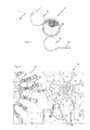
- Fig. 1 shows a schematic representation of a device 1 for inspecting plastic preforms 10.
- the plastic preform 10 has a mouth region 10b and a base body 10a.
- the reference character L refers to a longitudinal direction of the plastic preform 10.
- the plastic preform 10 is here observed by an image recording device 2, such as a camera, along its longitudinal direction L.
- the plastic preform is observed from below in this embodiment.
- the reference numeral 4 refers to a lighting device which also illuminates the plastic preform from below and with the beam path S.
- this illumination device has a multiplicity of light-emitting diodes 24, which advantageously direct monochrome light onto the plastic preform.
- the light here forms a cone around the view cone B of the camera. The light thus falls in comparison to the observation angle with a similar angle to the plastic preform 10 or its support ring 10c. In this way, the reflection on horizontal surfaces, such as the support ring underside, favors.
- the direction under which the plastic preform is illuminated and the direction under which it is observed is similar, that is, they deviate by less than 50 °, preferably by less than 40 ° and more preferably by less than 30 ° and especially preferably less than 20 ° from each other.
- the holding device 38 such as a clamp during hanging Preformtransport or a preferably closed ring when stationary Preformtransport and the background 28 lit. and thus causes disturbances in the picture.
- Full circumferential, annular retainers are preferred because they form a uniform background for the support ring.
- the holder 38 and the background surface 28 may have a rough, light-absorbing and abrasion-resistant surface. The passing major part of the light is thereby attenuated so far that the small amount of light reflected on the support ring becomes the image.
- the reference numeral 8 refers to a lens body, which is arranged here between the image pickup device 2 and the plastic preform 10 and also between the illumination device 4 and the plastic preform 10. This is at the in Fig. 1
- the outside area of the plastic preform is illuminated with the same lens body 8, which is also used for the pericentric imaging by the image recording device 2.
- the lens body 8 or the Fresnel lens deflects the individual light cones of the LEDs so that the desired large light cone S is formed. This procedure is easier and less expensive to implement than, for example, a perforated body in which each LED receives its own orientation.
- the reference numeral 28 in FIG Fig. 1 refers to a background, here advantageously rough, dark or black, but in particular absorbing for the emanating from the illumination device light is configured.
- the reference numeral 26 denotes a shielding device which prevents light from passing directly from the illumination device 4 to the image recording device 2, or via a reflection in the central lens region. In addition, it would also be possible for the individual light sources to lie directly against the lens body 8.
- the reference numeral 20 denotes an evaluation device which detects the images taken by the image recording device (cf. Fig. 4 ) evaluates.
- a rotational position of the plastic device is determined, for example, by the position of a (in Fig. 4 shown) marking is determined.
- the evaluation could also be used to read, for example, arranged on the support ring symbols and to identify in this way the plastic preform.
- Fig. 2 shows two possible beam paths in the observation of the plastic preform 10 and its support ring 10c. In each case, the support ring underside is observed and since the observation is oblique, the respective reflex is visible only by a double reflection.
- the light from the illumination device strikes the support ring 10c and is reflected at this ring to the main body 10a of the plastic preform 10.
- a second reflection towards the image recording device 2 takes place on the main body 10a of the plastic preform 10.
- the image recording device or camera sees on the main body 10a of the plastic preform the mirror image of the supporting ring.
- this inner mirror image can easily be partially covered by the main body 10a of the plastic preform 10.
- the light of the illumination device 4 first strikes the main body 10a of the plastic preform and is reflected from there to the support ring 10c.
- the support ring 10c then reflects the light to the camera where it (the support ring) appears brightly lit. This outer image area is less prone to cover, as is apparent Fig. 2 results, and is evaluated.
- the lens body 8 itself as a window.
- the transmitted-through ground glass also generates reflections on the surfaces and surface disturbances on the lens and the window that can be seen in the camera image. Therefore, the cost-effective Fresnel lens can be dispensed with in this case preferably.
- Lens and windows must preferably have an antireflective coating on all surfaces.
- the lens then breaks conical again the visual and light rays on the support ring.
- this method is more complicated than that with reference to Fig. 1 and 2 described method.
- the illumination device 4 and the observation device 2 above the plastic preform so as to determine a thread start (which is often flat and brightly reflected) vent slots, bayonet threaded parts and the like.
- plastic preforms made of material with diffusely scattering particles can also be inspected with the device according to the invention.
- the influence of the background is considerably lower than with transparent plastic preforms. Since the diffuse backscattering is much brighter than the reflection image, notches on the edge of the support ring are particularly easy to recognize.
- the light is strongly absorbed or swallowed; here, as with the transparent plastic preforms, the reflection light of the surface must be used.
- the Fig. 3 shows a further illustration to illustrate the measuring principle.
- This is a plastic preform, which is bent as a result of heating and, for example, a movement on a circular path or its base body 10a is inclined relative to the threaded portion 10b obliquely.
- a pericentric view of the camera device 2 takes place past the oblique main body 10a.
- the observation takes place here along the longitudinal direction of the non-curved plastic container.
- Fig. 4 shows a representation of an image taken with the device according to the invention. It can be clearly seen in this image, a marker 11 which is arranged on the support ring 10c of the container and which extends here in the radial direction R.
- the reference numeral 10d denotes an injection point of the plastic preform 10. On the basis of this image can be determined in this way the rotational position of the plastic preform with respect to its longitudinal axis and then the plastic preform are rotated.
- Fig. 5 shows a schematic representation of a system according to the invention for treating containers.
- the plastic preforms (not shown) run out of a heating device 52, which heats them.
- a transfer wheel 54 the plastic preforms are transferred to a treatment module or a contacting device 56, with which the plastic preforms are contacted at certain areas of their outer circumference and cooled here.
- the so partially cooled plastic preforms are transferred via a further transfer wheel 58 to a stretch blow molding machine 60 and can be formed there in particular to non-circular or oval containers.
- the rotational position of the plastic preforms is detected with respect to their longitudinal direction and then the plastic preforms are rotated by a predetermined angle with respect to their longitudinal axis.
- Fig. 6 shows a detailed representation of the area between the transfer wheel 54 and the contacting device 56.
- the transfer wheel 54 here has a plurality of gripping elements 62 such as gripping clamps, which grip and transport the plastic preform above its support ring here.
- the gripping devices are pivotally mounted on a main carrier 64 with individual carriers 66, whereby the transfer to the contacting device 56 is facilitated.
- the contacting device 56 has in each case contacting elements 57 which contact the plastic preforms partially on their outer wall.
- the contacting elements 57 can also be arranged on a carrier 66.
- the transfer wheel 54 can also be designed as a pitch delay star.
- the retaining clips 62 can be blackened. These retaining clips 62 can be seen in the picture both around and (in the case of transparent plastic preforms) through the support ring.
- the gripping clamps 62 are not completely around the plastic preform and have edges, gaps and structures. To the influence of such edges, columns and structures To keep the evaluation as low as possible, the retaining clips 62 are advantageously provided with a matte, rough and abrasion-resistant black surface.
- a (only schematically illustrated) rotary device 80 (which, for example, has stepper motors) is provided, which rotates with respect to the determined rotational position of the plastic preforms with respect to the longitudinal direction thereof.
- the rotating device can be designed as a separate module, but could also be arranged on or on the transfer wheel 54.
- the preforms are preferably individually rotated such that they are oriented after passing through the rotary device 80 in each case with the same rotational position.
- the rotating device 80 may have a mandrel or a gripping device, which preferably penetrates into the mouth of the plastic preforms and this rotates.
- said mandrel can also move along the transport path of the plastic preforms and in particular perform the rotation of the plastic preforms during this movement.
- the reference numeral 36 refers to a (only schematically illustrated) position detection device, such as a light barrier, which detects a position of the plastic preforms along their transport path and preferably serves to trigger a receptacle of the plastic container.
- an in Fig. 1 also shown matte black and / or light disc 28 provided on the opposite side as a background.
- matte black and / or light disc 28 provided on the opposite side as a background.
Landscapes
- Engineering & Computer Science (AREA)
- Manufacturing & Machinery (AREA)
- Mechanical Engineering (AREA)
- Physics & Mathematics (AREA)
- General Physics & Mathematics (AREA)
- Blow-Moulding Or Thermoforming Of Plastics Or The Like (AREA)
- Investigating Materials By The Use Of Optical Means Adapted For Particular Applications (AREA)
- Length Measuring Devices By Optical Means (AREA)
Abstract
Description
- Die vorliegende Erfindung bezieht sich auf eine Vorrichtung und ein Verfahren zur Erkennung der Lage von Behältnissen und insbesondere von Kunststoffvorformlingen. Aus dem Stand der Technik ist es seit langem bekannt, Kunststoffbehältnisse, insbesondere Kunststoffflaschen, dadurch herzustellen, dass zunächst Kunststoffvorformlinge erwärmt werden und anschließend die erwärmten Kunststoffvorformlinge mittels einer Umformungseinrichtung, wie beispielsweise einer Streckblasmaschine, zu Kunststoffbehältnissen umgeformt werden.
- Neben rotationssymmetrischen Behältnissen sind dabei aus dem Stand der Technik auch ovale Behältnisse, beispielsweise ovale PET-Flaschen, bekannt. Zur Herstellung solcher Behältnisse werden bekanntermaßen die Kunststoffvorformlinge in Umfangsrichtung ungleichmäßig erwärmt. Daneben sind jedoch aus dem Stand der Technik auch solche Behältnisse bekannt, die nicht nur oval ausgebildet sind, sondern deren Verschluss auch drehstellungsgenau auf die Mündung aufgeschraubt werden muss.
- Dies bedeutet, dass bereits vor dem Umformungsvorgang der Kunststoffvorformling hinsichtlich seiner Drehstellung orientiert sein muss. Das Problem besteht damit darin, dass oft die ovalen bzw. asymmetrischen Verschlüsse nicht einstellbar sind und je nach Lage des Bajonetts oder Gewindes eine unverrückbare Schließposition einnehmen. Nur wenn die Kunststoffvorformlinge bezüglich des Bajonetts oder Gewindes ausgerichtet, erwärmt und geblasen werden, sind die Verschlüsse dann in der Position, in der sie vom Kunden gewünscht wurden.
- Aus dem Stand der Technik sind Systeme bekannt, die für jeden neuen Kunststoffvorformling unterschiedlich gebaut werden müssen. Daneben schränkt die mechanische Ausrichtung der Kunststoffvorformlinge die Maschinenleistung stark ein. Denkbar wäre es, zur Erfassung Sensoren einzusetzen, die beispielsweise in den einzelnen Behandlungsstationen einer Streckblasmaschine angeordnet sind. In diesem Falle müsste jedoch eine Vielzahl von Sensoren, nämlich für jede Blas- oder Transportstation ein Sensor eingesetzt werden, die alle einjustiert werden müssen und deren Lage auch von dem jeweils zu behandelnden Kunststoffvorformling abhängt.
- Die
EP 1 279 477 A1 beschreibt eine Vorrichtung und ein Verfahren zum Blasformen von Flaschen. Dabei ist eine Dreheinrichtung vorgesehen, welche den Vorformling auf Basis von Signalen einer Sensoreinheit dreht, um ihn auf diese Weise in einer bestimmten Winkelstellung in einer Blasform anzuordnen. - Die
EP 0 835 736 B1 beschreibt eine Vorrichtung zum Blasformen und eine Vorrichtung zum Spritzstreckblasformen. Dabei sind Rotationseinrichtungen zum Rotieren des Vorformlings um seine Längsachse beim Transport des Vorformlings vorgesehen sowie Ausrichteinrichtungen, um den von dem Vorformling abstehenden Griff in eine vorgegebene Richtung auszurichten. - Der vorliegenden Erfindung liegt die Aufgabe zu Grunde, eine Vorrichtung zu schaffen, welche eine geometrische Position des Kunststoffvorformlings erfasst und insbesondere eine Drehstellung des Kunststoffvorformlings bezüglich seiner Längsachse erfasst. Dies wird erfindungsgemäß durch eine Vorrichtung nach Anspruch 1 und ein Verfahren nach Anspruch 13 erreicht. Vorteilhafte Ausführungsformen und Weiterbildungen sind Gegenstand der Unteransprüche.
- Eine erfindungsgemäße Vorrichtung zum Erkennen einer geometrischen Lage von Kunststoffbehältnissen und insbesondere von Kunststoffvorformlingen, wobei die Kunststoffbehältnisse einen Grundkörper und einen Gewindebereich aufweisen, weist eine Bildaufnahmeeinrichtung auf, welche ein ortsaufgelöstes Bild des Kunststoffbehältnisses bzw. eines Bereiches des Kunststoffbehältnisses aufnimmt. Dabei ist die Bildaufnahmeeinrichtung derart angeordnet, dass sie das Kunststoffbehältnis im Wesentlichen entlang seiner Längsrichtung beobachtet.
- Erfindungsgemäß weist die Vorrichtung eine Beleuchtungseinrichtung auf, welche wenigstens einen von der Bildaufnahmeeinrichtung beobachteten Bereich des Kunststoffbehältnisses beleuchtet sowie eine Auswerteeinrichtung, welche auf Basis eines von der Bildaufnahmeeinrichtung aufgenommenen Bildes eine Drehstellung des Kunststoffbehältnisses bezüglich dessen Längsrichtung bestimmt. Vorzugsweise bestimmt die Auswerteeinrichtung auf Basis genau eines von der Bildaufnahmeeinrichtung aufgenommenen Bildes die Drehstellung des Kunststoffvorformlings. Daneben wäre es auch denkbar, dass die Auswerteeinrichtung auf Basis eines von der Bildaufnahmeeinrichtung aufgenommenen Bildes eine Information ermittelt, welche beispielsweise aus einer Markierung des Kunststoffbehältnisses ablesbar ist. Es wird daher vorgeschlagen, dass die Beobachtung des Behältnisses von unterhalb oder von oberhalb des Behältnisses und insbesondere im Wesentlichen entlang seiner Längsrichtung erfolgt. Dabei wäre es bevorzugt möglich, dass die Bildaufnahmeeinrichtung in Längsrichtung unterhalb oder oberhalb des Behältnisses angeordnet ist. Es wäre jedoch auch möglich, dass Spiegel vorgesehen sind, und die Bildaufnahmeeinrichtung an einer andere Position als unterhalb des Behältnisses oder oberhalb des Behältnisses angeordnet ist, so dass gleichwohl (mit über Umlenkspiegel verlaufendem Strahlengang) in Längsrichtung des Behältnisses beobachtet wird.
- Der Vorteil des vorgeschlagenen Systems liegt darin, dass dieses im Vergleich zu Systemen, welche aus dem Stand der Technik bekannt sind, berührungslos mit Licht und einer Bildaufnahmeeinrichtung, wie insbesondere einer Kamera, arbeitet. Dadurch, dass sich die Bildaufnahmeeinrichtung vorteilhaft unterhalb oder über den Kunststoffvorformlingen befindet, ist es möglich, dass die Inspektion des Kunststoffvorformlings ohne Elemente auskommt, welche im Bereich einer Transportbahn der Kunststoffvorformlinge liegen. Auf diese Weise können Störungen von Transporteuren oder Transfersternen vermieden werden.
- Ein weiterer Vorteil der Beobachtung von oben oder von unten ergibt sich daraus, dass mit nur einem Bild die Drehlage des Kunststoffvorformlings erfasst werden kann und auf diese Weise keine Abwicklung bzw. Mehrfachansichten nötig sind. Im Falle einer horizontalen Inspektion, beispielsweise in der Transportebene des Kunststoffvorformlings, würde die Notwendigkeit entstehen, mehrere Aufnahmen von dem Kunststoffvorformling zu machen. Durch die Aufnahme von oben oder unten kann die Drehlage des Kunststoffvorformlings auch an Stellen, an denen die Kunststoffvorformlinge starr gehalten werden, bestimmt werden.
- Bei einer weiteren vorteilhaften Ausführungsform findet die Inspektion des Kunststoffvorformlings in einem Transferstern statt und das Ergebnis der besagten Inspektion wird an eine nachfolgende Maschine wie beispielsweise an einen Behandlungsstern insbesondere an die Servomotoren dieses Behandlungssternes übermittelt. Diese Servomotoren können dann die Kunststoffvorformlinge in eine gewünschte Drehlage drehen.
- Vorteilhaft ist die Beleuchtungseinrichtung im Wesentlichen ringförmig bezüglich der Längsrichtung des Kunststoffbehältnisses angeordnet bzw. ausgebildet. So wäre es beispielsweise möglich, dass eine Vielzahl von Lichtquellen wie beispielsweise LED's ringförmig um die Längsachse des Kunststoffbehältnisses angeordnet ist. Daneben könnten jedoch auch Leuchtringe und dergleichen verwendet werden. Vorteilhaft wird das Behältnis aus wenigstens zwei, bevorzugt aus wenigstens drei und besonders bevorzugt aus mehreren unterschiedlichen Richtungen beleuchtet, sodass auf diese Weise besonders vorteilhaft eine voll umfängliche Beleuchtung des Behältnisses und insbesondere dessen Tragringes ermöglicht wird.
- Diese Vorgehensweise ist für mehrere Arten von Kunststoffvorformlingen geeignet, eine Anpassung kann durch Modifizierung der Software - Auswerteparameter erfolgen, sodass vorteilhaft keine mechanischen Umbauten bei der Umstellung auf andere Kunststoffvorformlinge nötig sind.
- Bei einer weiteren vorteilhaften Ausführungsform ist die Beleuchtungseinrichtung zwischen der Bildaufnahmeeinrichtung und dem Kunststoffbehältnis angeordnet. Auf diese Weise kann verhindert werden, dass Licht unmittelbar von der Beleuchtungseinrichtung in die Bildaufnahmeinrichtung gelangt.
- Bei einer weiteren vorteilhaften Ausführungsform ist die Bildaufnahmeeinrichtung unterhalb des Kunststoffbehältnisses angeordnet bzw. beobachtet die Bildaufnahmeeinrichtung das Kunststoffbehältnisses von unterhalb. Einfache Markierungen an der Unterseite oder am Rand der Kunststoffvorformlinge, beispielsweise deren Tragringe, sind dabei ausreichend, um die Bildaufnahme zu gewährleisten. Auf diese Weise verbleibt an einer Oberseite des Tragringes genügend Fläche, um beispielsweise für den nachfolgenden Blasvorgang eine Abdichtung am Tragring durchführen zu können. Es wäre jedoch auch möglich, die Drehstellung der Kunststoffvorformlinge anhand von Merkmalen des Gewindes zu erfassen und hier eine Beobachtung von oben durchzuführen. Bei dieser Vorgehensweise können auch mechanische Nocken zwischen den Tragringen und dem Gewinde entfallen.
- Unter einer Beobachtung in Längsrichtung der Kunststoffvorformlinge wird verstanden, dass eine Beobachtungsrichtung bezüglich der Längsrichtung der Behältnisse dem Betrag nach um nicht mehr als 20°, bevorzugt um nicht mehr als 10° und besonders bevorzugt um nicht mehr als 5°, abweicht.
- Vorteilhaft werden perizentrische Abbildungen bzw. Beobachtungen und besonders bevorzugt auch perizentrische Beleuchtungen verwendet das heißt, die Kunststoffvorformlinge werden entlang ihres vollständigen Umfangs beleuchtet und auch beobachtet. Vorteilhaft ist auch die Beleuchtungseinrichtung unterhalb des Kunststoffbehältnisses bzw. dessen Transportpfad angeordnet. Damit sind vorteilhaft sowohl die Beleuchtungseinrichtung als auch die Bildaufnahmeeinrichtung unterhalb der Kunststoffvorformlinge bzw. deren Transportpfad angeordnet. So können die Beleuchtungseinrichtungen und die Beobachtungseinrichtungen als modulare Einheit aufgebaut sein.
- Wie oben erwähnt, ist die Beleuchtungseinrichtung vorteilhaft derart angeordnet, dass von der Beleuchtungseinrichtung ausgehendes Licht nicht direkt auf die Bildaufnahmeeinrichtung trifft. So wäre es beispielsweise möglich, dass Abschirmungen vorgesehen sind, welche einen direkten Strahlengang zwischen der Beleuchtungseinrichtung und der Bildaufnahmeeinrichtung behindern.
- Bei einer weiteren vorteilhaften Ausführungsform ist zwischen der Beleuchtungseinrichtung und den Kunststoffbehältnissen ein Linsenkörper angeordnet. Vorteilhaft handelt es sich dabei um eine Linse mit einem kleinen Öffnungsverhältnis (Brennweite/Durchmesser), welches zwischen 2,0 und 0,5, bevorzugt zwischen 1,5 und 0,7 liegt. Besonders bevorzugt wird eine Linse verwendet, welche an wenigstens einer ihrer Oberflächen eine Struktur aufweist und besonders bevorzugt handelt es sich bei der verwendeten Linse um eine Fresnel-Linse.
- Weiterhin weist die Beleuchtungseinrichtung vorteilhaft eine Vielzahl von einfarbigen LED's auf. Dabei wäre es zusätzlich bevorzugt möglich, dass ein auf der Fresnel-Linse aufsitzender Ring den Sicht- und Beleuchtungsbereich der Fresnel-Linse voneinander trennt, so dass Störreflexe im Kamerabild verhindert werden. Die einfarbigen LEDs erlauben, die Linse gleichzeitig auch für das abbildende System zu nutzen. Bei Verwendung von Licht mit stark unterschiedlichen Wellenlängen (weißes Licht, RGB-LEDs etc.) wird das Bild durch den Farbfehler der Billiglinse sehr unscharf.
- Die Auswahl einer Fresnel-Linse hat insbesondere auch Vorteile hinsichtlich der Kosten. Anstelle einer Fresnel-Linse könnten auch perizentrische Objektive verwendet werden, welche möglicherweise die Abbildung verbessern, allerdings sehr teuer sind. Normale Perizentrische Objektive sind so teuer, weil sie große Linsensysteme haben, die für eine einwandfreie Abbildung korrigiert wurden. Sie werden deshalb üblicherweise nicht für die Beleuchtung eingesetzt.
- Vorteilhaft liegt ein Abstand zwischen der besagten Linse und dem Tragring eines zu beobachtenden Kunststoffvorformlings zwischen 150 und 300 mm, bevorzugt zwischen 170 und 250 mm und besonders bevorzugt zwischen 190 und 210 mm. Vorteilhaft wird weiterhin ein Linsenkörper verwendet, der eine Brennweite aufweist, welche im wesentlichen dem Abstand der Linse zu dem Tragering des Kunststoffvorformlings entspricht, bzw. sich besonders bevorzugt in einem Bereich von plus/minus 20 % dieses Abstandes hält. Auf diese Vorgehensweise wird das Licht optimal auf dem Tragring der Kunststoffvorformlinge konzentriert.
- Weil während einer normalen Betrachtung des Tragrings des Kunststoffvorformlings von unten, in der Verlängerung der Längsachse des Kunststoffvorformlings, oft der untere Preformteil den Tragring verdeckt, kann durch die Verwendung einer perizentrischen Abbildung der Tragring besser beobachtet werden. Weiterhin tritt in der Praxis das Problem auf, dass die Zentripetalkraft die weichen und erhitzten Kunststoffvorformlinge beim Transport auf gekrümmten Bahnen verbiegt. In diesem Falle verdecken sie auch oft einseitig den Tragring. Bei der perizentrischen Abbildung wird umfänglich von schräg außen auf den Tragring geblickt.
- Auf diese Weise ist es möglich, dass der Kunststoffvorformling an seinem unteren Ende nahezu den Durchmesser des Tragrings aufweisen kann und sich daneben auch seitlich biegen kann. Daneben wird auch eine gewisse Lagetoleranz bezüglich der Greifeinrichtung bzw. Haltevorrichtung, welche den Kunststoffvorformling während seines Transports hält, ermöglicht.
- Bevorzugt ist auch zwischen der Beobachtungseinrichtung und dem Kunststoffbehältnis ein Linsenkörper angeordnet. Vorteilhaft handelt es sich hierbei um den gleichen Linsenkörper, der auch zwischen der Beleuchtungseinrichtung und dem Kunststoffbehältnis angeordnet ist.
- Bei einer weiteren bevorzugten Ausführungsform beleuchtet die Beleuchtungseinrichtung einen Tragring des Kunststoffbehältnisses und die Bildaufnahmeeinrichtung nimmt ein Bild des beleuchteten Tragrings auf. Auf diese Weise kann insbesondere durch Markierungen an dem Tragring sehr leicht auf eine Drehstellung des Kunststoffbehältnisses bezüglich seiner Längsachse geschlossen werden.
- Weiterhin ist es auch möglich, dass durch eine Variation des Abstandes der Bildaufnahmeeinrichtung zu der Fresnel-Linse der Grad der Perizentrie eingestellt wird. Je größer der Abstand der Bildaufnahmeeinrichtung zu der Linse ist, desto größer ist der sich ergebene Betrachtungswinkel, falls die übrigen Parameter beibehalten werden. Gegebenenfalls wäre es auch möglich, für bestimmte Betrachtungen die Linse durch eine andere Linse mit entsprechend größerer oder kleinerer Brennweite zu ersetzen.
- Vorzugsweise werden Fresnellinse und Beleuchtung (sie sind Teil des Gehäuses!) nur grundeingestellt, und weitere Einstellungen erfolgen mit der Kameraentfernung, weil so nur die kleine Kamera und nicht die ganze Konstruktion bewegt werden muss.
- Falls sich das Kameraobjektiv im Brennpunkt der Fresnel-Linse befindet, wird auf diese Weise eine telezentrische Abbildung erhalten, bzw. eine vollständig gerade Sicht. Mit zunehmendem Abstand wird immer schräger auf den Tragring des Kunststoffvorformlings geblickt. Dabei nimmt das Bild des Tragrings einen immer größeren Bereich der Fresnel-Linse ein. Auf diese Weise kann das System optimal auf verschiedene Tragring- und Mündungsgrößen eingestellt werden. Bevorzugt ist daher eine Position der Bildaufnahmeeinrichtung bezüglich des Linsenkörpers verstellbar. Bevorzugt ist auch ein Abstand zwischen dem Linsenkörper und dem beobachteten Kunststoffvorformling verstellbar.
- Vorzugsweise ist ein Abstand zwischen dem Linsenkörper und der Bildaufnahmeeinrichtung größer als die Brennweite des Linsenkörpers, und besonders bevorzugt liegt der Abstand zwischen der 1,5 - fachen Brennweite und der 3 - fachen Brennweite und besonders bevorzugt zwischen der 1,8 - fachen Brennweite und der 2,4 - fachen Brennweite. Vorteilhaft ist daher die Bildaufnahmeeinrichtung in Richtung der Längsrichtung des Kunststoffvorformlings verstellbar.
- Vorteilhaft liegt eine Aufbauhöhe gerechnet von dem Linsenkörper bis zu dem Ende der Bildaufnahmeeinrichtung in einem Bereich von 400 bis 800 mm. Um die vertikale Ausdehnung zu reduzieren, ist es auch möglich, zwischen die Fresnel-Linse und die Kamera einen Umlenkspiegel einzufügen, so dass die Beobachtungsrichtung der Kamera selbst zwar senkrecht zur Längsrichtung des Kunststoffvorformlings liegt, jedoch gleichzeitig über den besagten Umlenkspiegel ein Bild in Längsrichtung des Kunststoffvorformlings aufnimmt. Auf diese Weise lässt sich das System kompakter und besser an die Platzverhältnisse in den jeweiligen Maschinen anpassen. Für die Funktion der Vorrichtung ist jedoch die besagte Strahlumlenkung nicht notwendig.
- Die vorliegende Erfindung ist weiterhin auf eine Anlage zum Behandeln von Kunststoffvorformlingen mit einer Vorrichtung der oben beschriebenen Art gerichtet sowie einer Dreheinrichtung, welche den Kunststoffvorformling unter Berücksichtigung einer von der Auswertungseinrichtung bestimmten Drehlage des Kunststoffbehältnisses um bzw. bezüglich dessen Längsrichtung dreht. Vorteilhaft ist die besagte Dreheinrichtung in einer Transportrichtung der Kunststoffvorformlinge nach der erfindungsgemäßen Vorrichtung angeordnet. In Reaktion auf eine von der erfindungsgemäßen Vorrichtung bestimmte Drehstellung des Kunststoffvorformlings dreht die Dreheinrichtung diesen um seine Längsachse.
- Bei einer weiteren vorteilhaften Ausführungsform weist die Anlage eine Transporteinrichtung auf, welche den Kunststoffvorformling entlang eines Transportpfades gegenüber der Vorrichtung bewegt. Bei dieser Transporteinrichtung kann es sich beispielsweise um ein Transferrad handeln, an dem eine Vielzahl von Greifelementen angeordnet ist, welche jeweils die Kunststoffvorformlinge halten. Vorteilhaft erfolgt der Transport der Kunststoffvorformlinge gegenüber der erfindungsgemäßen Vorrichtung kontinuierlich. In einer weiteren vorteilhaften Ausführungsform ist der erfindungsgemäßen Vorrichtung eine Blasmaschine, insbesondere eine Streckblasmaschine, nachgeschaltet, welche die Kunststoffvorformlinge zu Kunststoffbehältnissen umformt.
- Bei einer weiteren vorteilhaften Ausführungsform weist die Vorrichtung auch eine Positionserfassungseinrichtung auf, welche eine Position des Kunststoffvorformlings, insbesondere während dessen Transports und entlang des Transportpfades, erfasst. Dabei kann es sich beispielsweise um eine Lichtschrankeneinrichtung handeln, welche jeweils die Position der Kunststoffvorformlinge bestimmt und in Reaktion auf den jeweiligen Ort der Kunststoffvorformlinge einen Lichtpuls der Beleuchtungseinrichtung in Abhängigkeit von der Position des Kunststoffvorformlings auslöst. Vorteilhaft ist dabei diese Lichtschrankeneinrichtung entlang des Transportpfades der Behältnisse kurz vor der erfindungsgemäßen Vorrichtung angeordnet, so dass einerseits in Reaktion auf die ermittelte Position des Kunststoffvorformlings genügend Zeit zum Auslösen des Lichtpulses verbleibt und andererseits die Position mit hinreichender Genauigkeit festgestellt werden kann.
- Die vorliegende Erfindung bezieht sich weiterhin auf ein Verfahren zum Erfassen einer geometrischen Position von Kunststoffbehältnissen und insbesondere einer Drehstellung von Kunststoffvorformlingen bezüglich ihrer Längsachse, wobei eine Beleuchtungseinrichtung den Kunststoffvorformling beleuchtet und eine Beobachtungseinrichtung den von der Beleuchtungseinrichtung beleuchteten Kunststoffvorformling im wesentlichen entlang seiner Längsrichtung beobachtet und ein Bild des Kunststoffvorformlings aufnimmt.
- Erfindungsgemäß wird aus mindestens einem aufgenommenen Bild eine Drehstellung des Kunststoffvorformlings bezüglich seiner Längsrichtung ermittelt.
- Bei einem weiteren bevorzugten Verfahren wird der Kunststoffvorformling in Reaktion auf das aufgenommene Bild um seine Längsachse gedreht.
- Vorteilhaft wird der Kunststoffvorformling aus mehreren Richtungen beobachtet. Bei einem weiteren vorteilhaften Verfahren wird ein Tragring des Kunststoffvorformlings beleuchtet und vorteilhaft auch dieser beleuchtete Bereich von der Bildaufnahmeeinrichtung beobachtet.
- Vorteilhaft wird der Kunststoffvorformling - wie oben erwähnt - perizentrisch beleuchtet, wobei das Licht besonders vorteilhaft auf den Tragring bzw. die Mündung konzentriert wird und dadurch ein helles Bild entsteht.
- Bevorzugt wird aus genau einem aufgenommenen Bild die Drehstellung des Kunststoffvorformlings ermittelt, wobei besonders bevorzugt auch auf eine abwickelnde Preformbewegungen für die Inspektion verzichtet wird.
- Weitere Vorteile und Ausführungsformen ergeben sich aus den beigefügten Zeichnungen.
- Darin zeigen:
- Fig. 1 Fig. 2
- eine schematische Darstellung einer erfindungsgemäßen Vorrichtung; eine Darstellung der Beobachtung von Kunststoffvorformlingen;
- Fig. 3
- eine weitere Möglichkeiten der Beobachtung von Kunststoffvorformlingen;
- Fig. 4
- ein aufgenommenes Bild eines Kunststoffvorformlings;
- Fig. 5
- eine schematische Darstellung einer Anlage zum Behandeln von Kunststoffvorformlingen und
- Fig. 6
- eine Detailansicht einer Anlage zum Behandeln von Kunststoffvorformlingen;
-
Fig. 1 zeigt eine schematische Darstellung einer Vorrichtung 1 zum Inspizieren von Kunststoffvorformlingen 10.Dabei weist der Kunststoffvorformling 10 einen Mündungsbereich 10b und einen Grundköper 10a auf. Das Bezugszeichen L bezieht sich auf eine Längsrichtung des Kunststoffvorformlings 10. - Man erkennt, dass der Kunststoffvorformling 10 hier von einer Bildaufnahmeeinrichtung 2, wie einer Kamera, entlang seiner Längsrichtung L beobachtet wird. Dabei wird bei dieser Ausgestaltung der Kunststoffvorformling von unten beobachtet. Das Bezugszeichen 4 bezieht sich auf eine Beleuchtungseinrichtung, welche den Kunststoffvorformling hier ebenfalls von unten her und mit dem Strahlengang S beleuchtet. Diese Beleuchtungseinrichtung weist hier eine Vielzahl von Leuchtdioden 24 auf, welche vorteilhaft einfarbiges Licht auf den Kunststoffvorformling richten. Wie in
Fig. 1 erkennbar, bildet das Licht hier einen Kegel rund um den Sichtkegel B der Kamera. Das Licht fällt somit im Vergleich zum Beobachtungswinkel mit einen ähnlichen Winkel auf den Kunststoffvorformling 10 bzw. dessen Tragring 10c. Auf diese Weise wird die Reflexion an horizontalen Flächen, wie beispielsweise der Tragringunterseite, begünstigt. Vorteilhaft ist daher die Richtung, unter welcher der Kunststoffvorformling beleuchtet wird und die Richtung, unter welcher er beobachtet wird, ähnlich das heißt, sie weichen um weniger als 50°, bevorzugt um weniger als 40° und besonders bevorzugt um weniger als 30° und besonders bevorzugt um weniger als 20° voneinander ab. - Da bei durchsichtigem Material wie dem Material der Kunststoffvorformlinge das meiste Licht durch den Tragring 10c hindurchtritt, ist es möglich, dass das durchgehende Licht die Haltevorrichtung 38 wie eine Klammer beim hängenden Preformtransport bzw. einen vorzugsweise geschlossenen Ring beim stehenden Preformtransport und den Hintergrund 28, beleuchtet und somit Störungen im Bild verursacht. Vollumfängliche, ringförmige Haltevorrichtungen sind bevorzugt, weil sie einen gleichmäßigen Hintergrund für den Tragering bilden.
- Daher kann die Haltevorrichtung 38 und die Hintergrundfläche 28 eine raue, lichtabsorbierende und abriebfeste Oberfläche besitzen. Der durchtretende Hauptanteil des Lichts wird dadurch so weit abgeschwächt, dass der kleine, an dem Tragering reflektierte Lichtanteil bildbestimmend wird.
- Das Bezugszeichen 8 bezieht sich auf einen Linsenkörper, der hier zwischen der Bildaufnahmeeinrichtung 2 und dem Kunststoffvorformling 10 bzw. auch zwischen der Beleuchtungseinrichtung 4 und dem Kunststoffvorformling 10 angeordnet ist. Damit wird bei der in
Fig. 1 gezeigten Ausführungsform der Außenbereich des Kunststoffvorformlings mit dem gleichen Linsenkörper 8, der auch für die perizentrische Abbildung durch die Bildaufnahmeeinrichtung 2 verwendet wird, beleuchtet. Auf diese Weise kann eine einfache, ebene und insbesondere mit LEDs bestückte Ringlampe zur Beleuchtung benutzt werden. Der Linsenkörper 8 bzw. die Fresnel-Linse lenkt die einzelnen Lichtkegel der LEDs so um, dass der gewünschte große Lichtkegel S entsteht. Diese Vorgehensweise ist einfacher und kostengünstiger zu realisieren als beispielsweise ein Lochkörper, in dem jede LED ihre eigene Ausrichtung erhält. - Damit wird hier die Beleuchtung durch den Beleuchtungshohlkegel S erreicht. Das Bezugszeichen 28 in
Fig. 1 bezieht sich auf einen Hintergrund, der hier vorteilhaft rau, dunkel bzw. schwarz, insbesondere jedoch absorbierend für das von der Beleuchtungseinrichtung ausgehende Licht, ausgestaltet ist. - Das Bezugszeichen 26 kennzeichnet eine Abschirmungseinrichtung, welche verhindert, dass Licht unmittelbar, oder über eine Reflexion im zentralen Linsenbereich von der Beleuchtungseinrichtung 4 zu der Bildaufnahmeeinrichtung 2 gelangt, Daneben wäre es auch möglich, dass die einzelnen Lichtquellen unmittelbar an dem Linsenkörper 8 anliegen.
- Das Bezugszeichen 20 kennzeichnet eine Auswerteeinrichtung, welche die von der Bildaufnahmeeinrichtung aufgenommenen Bilder (vgl.
Fig. 4 ) auswertet. Dabei wird insbesondere eine Drehstellung der Kunststoffeinrichtung ermittelt, etwa, indem die Position einer (inFig. 4 gezeigten) Markierung bestimmt wird. Daneben könnte die Auswerteeinrichtung jedoch auch verwendet werden, um beispielsweise auf dem Tragring angeordnete Symbole auszulesen und um auf diese Weise den Kunststoffvorformling zu identifizieren. -
Fig. 2 zeigt zwei mögliche Strahlengänge bei der Beobachtung des Kunststoffvorformlings 10 bzw. dessen Tragrings 10c. In jedem Fall wird die Tragringunterseite beobachtet und da die Beobachtung schräg erfolgt, ist der jeweilige Reflex erst durch eine Doppelreflektion sichtbar. - Im Falle des ersten Beobachtungswegs B1 trifft das Licht der Beleuchtungseinrichtung auf den Tragring 10c auf und wird an diesem Ring zum Grundkörper 10a des Kunststoffvorformlings 10 reflektiert. An dem Grundkörper 10a des Kunststoffvorformlings 10 erfolgt eine zweite Reflexion hin zur Bildaufnahmeeinrichtung 2. Die Bildaufnahmeeinrichtung bzw. Kamera sieht auf dem Grundkörper 10a des Kunststoffvorformlings das Spiegelbild des Tragrings. Dieses innere Spiegelbild kann jedoch leicht durch den Grundkörper 10a des Kunststoffvorformlings 10 teilverdeckt werden.
- Daneben ist auch ein zweiter Beobachtungsweg möglich. Hier trifft das Licht der Beleuchtungseinrichtung 4 zunächst auf den Grundkörper 10a des Kunststoffvorformlings und wird von dort auf den Tragring 10c reflektiert. Der Tragring 10c reflektiert dann das Licht zur Kamera, wo er (der Tragring) hell erleuchtet erscheint. Dieser äußere Bildbereich ist weniger abdeckungsgefährdet, wie sich aus
Fig. 2 ergibt, und wird ausgewertet. - Es hat sich gezeigt, dass auf diese Weise die Beleuchtung zufriedenstellend arbeitet. Daher wurde bei dieser Ausführungsform auf eine echte kegelförmige bzw. koaxiale Beleuchtung verzichtet. Diese könnte jedoch ebenfalls verwendet werden. Bei einer derartigen Anordnung wäre es möglich, dass vor der Bildaufnahmeeinrichtung ein halbdurchlässiger Spiegel das Licht der LEDs einspiegelt. In diesem Falle ist bevorzugt vor den Beleuchtungseinrichtungen eine Licht streuende Mattscheibe vorgesehen, damit keine hellen punktförmigen Reflexe auf der nachfolgenden Linse und dem (hier nicht gezeichneten) Fenster auftreten.
- Daneben wäre es denkbar, den Linsenkörper 8 selbst als Fenster zu verwenden Auch die durchstrahlte Mattscheibe erzeugt Reflexe an den Oberflächen und Oberflächenstörungen von der Linse und dem Fenster, die im Kamerabild zu sehen sind. Deshalb kann in diesem Fall bevorzugter Weise auf die kostengünstige Fresnellinse verzichtet werden. Linse und Fenster müssen bevorzugt eine Antireflexbeschichtung auf allen Oberflächen aufweisen.
- In diesem Falle bricht die Linse dann wieder kegelförmig die Sicht- und Lichtstrahlen auf den Tragring. Dieses Verfahren ist jedoch aufwendiger als das unter Bezugnahme auf
Fig. 1 und 2 beschriebene Verfahren. - Wie erwähnt, wäre es auch möglich, die Beleuchtungseinrichtung 4 sowie die Beobachtungseinrichtung 2 oberhalb des Kunststoffvorformlings anzuordnen, um auf diese Weise einen Gewindeanfang (der oft eben ist und hell reflektiert) Vent-Slots, Bajonett-Gewindeteile und dergleichen zu ermitteln.
- Weiterhin wäre es auch möglich, sowohl ein Erkennungssystem über- als auch unterhalb des Kunststoffvorformlings vorzusehen. Diese könnte bei speziellen Kunststoffvorformlingen in Betracht kommen oder auch bei Kunststoffvorformlingsorten, welche unterschiedliche Markierungen aufweisen, um so einen umbaufreien Sortenwechsel zu ermöglichen.
- Daneben können mit der erfindungsgemäßen Vorrichtung auch Kunststoffvorformlinge aus Material mit diffus streuenden Partikeln inspiziert werden. Bei hellen und/oder diffusen Kunststoffvorformlingen ist der Einfluss des Hintergrunds wesentlich geringer als bei durchsichtigen Kunststoffvorformlingen. Da hier die diffuse Rückstreuung wesentlich heller als das Reflexbild ist, sind so durchgehende Kerben am Tragringrand besonders leicht zu erkennen. Bei dunklem diffusem Material wird das Licht stark absorbiert bzw. verschluckt, hier muss wie bei den durchsichtigen Kunststoffvorformlingen mit dem Reflexlicht der Oberfläche gearbeitet werden.
- Die
Fig. 3 zeigt eine weitere Darstellung zur Veranschaulichung des Messprinzips. Dabei handelt es sich hier um einen Kunststoffvorformling, der in Folge der Erwärmung und beispielsweise einer Bewegung auf einem kreisförmigen Pfad geknickt ist bzw. dessen Grundkörper 10a gegenüber dem Gewindebereich 10b schräg geneigt ist. Auch hier erfolgt ein perizentrischer Blick der Kameraeinrichtung 2 an dem schrägen Grundkörper 10a vorbei. Die Beobachtung erfolgt hier entlang der Längsrichtung des ungekrümmten Kunststoffbehältnisses. Es wäre jedoch auch möglich, die Blickrichtung bewusst auf eine zu erwartende Krümmung des Kunststoffvorformlings anzupassen, d.h., die Behältnisse insbesondere unter einem vorgegebenen schrägen Winkel zu beobachten. -
Fig. 4 zeigt eine Darstellung eines mit der erfindungsgemäßen Vorrichtung aufgenommenen Bildes. Man erkennt in diesem Bild deutlich eine Markierung 11, die an dem Tragring 10c des Behältnisses angeordnet ist und die sich hier in radialer Richtung R erstreckt. - Das Bezugszeichen 10d bezeichnet einen Anspritzpunkt des Kunststoffvorformlings 10. Anhand dieses Bildes kann auf diese Weise die Drehstellung des Kunststoffvorformlings bezüglich seiner Längsachse ermittelt werden und anschließend der Kunststoffvorformling gedreht werden.
-
Fig. 5 zeigt eine schematische Darstellung einer erfindungsgemäßen Anlage zum Behandeln von Behältnissen. Dabei laufen die (nicht gezeigten) Kunststoffvorformlinge aus einer Heizeinrichtung 52, welche diese erwärmt, aus. Über ein Transferrad 54 werden die Kunststoffvorformlinge an ein Behandlungsmodul bzw. eine Kontaktierungseinrichtung 56 übergeben, mit dem die Kunststoffvorformlinge an bestimmten Bereichen ihres Außenumfangs kontaktiert und hier gekühlt werden. Anschließend werden die so partiell gekühlten Kunststoffvorformlinge über ein weiteres Transferrad 58 an eine Streckblasmaschine 60 übergeben und können dort insbesondere zu nicht kreisförmigen bzw. ovalen Behältnissen geformt werden.
Entlang des Transferrades 54 wird die Drehstellung der Kunststoffvorformlinge bezüglich deren Längsrichtung erfasst und anschließend werden die Kunststoffvorformlinge um einen vorgegebenen Winkel bezüglich ihrer Längsachse gedreht. -
Fig. 6 zeigt eine detaillierte Darstellung des Bereiches zwischen dem Transferrad 54 und der Kontaktierungseinrichtung 56. Man erkennt, dass das Transferrad 54 hier eine Vielzahl von Greifelementen 62 wie Greifklammern aufweist, welche den Kunststoffvorformling hier oberhalb seines Tragringes greifen und transportieren. Dabei sind die Greifeinrichtungen an einem Hauptträger 64 mit Einzelträgern 66 schwenkbar gelagert, wodurch die Übergabe an die Kontaktierungseinrichtung 56 erleichtert wird. Die Kontaktierungseinrichtung 56 weist jeweils Kontaktierungselemente 57 auf, welche die Kunststoffvorformlinge partiell an ihrer Außenwandung kontaktieren. Auch die Kontaktierungselemente 57 können dabei an einem Träger 66 angeordnet sein. Das Transferrad 54 kann dabei auch als Teilungsverzugsstern ausgeführt sein. - Bei einigen Anwendungen ist es auch möglich, die Halteklammern 62 geschwärzt auszuführen. Diese Halteklammern 62 sind sowohl um, als auch (im Falle von durchsichtigen Kunststoffvorformlingen) durch den Tragring hindurch im Bild zu sehen. Die Greifklammern 62 liegen dabei jedoch nicht voll umfänglich um den Kunststoffvorformling an und weisen Kanten, Spalten und Strukturen auf. Um den Einfluss derartiger Kanten, Spalten und Strukturen auf die Auswertung möglichst gering zu halten, werden vorteilhaft die Halteklammern 62 mit einer matten, rauen und abriebfesten schwarzen Oberfläche versehen.
- Zwischen der Inspektion der Kunststoffvorformlinge 10 bzw. der Ermittlung der Drehstellung der Kunststoffvorformlinge bzgl. der Längsrichtung L einerseits und der Zuführung zu der Kontaktierungseinrichtung 56 werden die Kunststoffvorformlinge bezüglich ihrer Längsrichtung gedreht. Zu diesem Zweck ist eine (nur schematisch dargestellte) Dreheinrichtung 80 (welche beispielsweise Schrittmotoren aufweist) vorgesehen, die in Abhängigkeit von der ermittelten Drehstellung der Kunststoffvorformlinge diese bezüglich deren Längsrichtung dreht. Die Dreheinrichtung kann dabei als eigenes Modul ausgebildet sein, könnte jedoch auch auf bzw. an dem Transferrad 54 angeordnet sein.
- Dabei werden die Vorformlinge bevorzugt individuell derart gedreht, dass sie nach Durchlaufen der Dreheinrichtung 80 jeweils mit gleicher Drehstellung orientiert sind.
Die Dreheinrichtung 80 kann dabei einen Dorn oder eine Greifeinrichtung aufweisen, welche bevorzugt in die Mündung der Kunststoffvorformlinge eindringt und diese so dreht. Dabei kann sich der besagte Dorn auch entlang des Transportpfades der Kunststoffvorformlinge mitbewegen und insbesondere während dieser Bewegung auch die Drehung der Kunststoffvorformlinge durchführen. Das Bezugszeichen 36 bezieht sich auf eine (nur schematisch dargestellte) Positionserfassungseinrichtung, wie etwa eine Lichtschranke, welche eine Position der Kunststoffvorformlinge entlang deren Transportpfad erfasst und bevorzugt zum Auslösen einer Aufnahme des Kunststoffbehältnisses dient. - Zusätzlich ist eine in
Fig. 1 gezeigte ebenfalls matte schwarze und/oder helle Scheibe 28 auf der gegenüber liegenden Seite als Hintergrund vorgesehen. Auf diese Weise werden Störungen im Bild, wie die Sicht auf bewegliche Maschinenteile oder Fremdlicht durch Fenster oder Oberlichter der Maschinenhalle, vermieden. Insgesamt wird durch einen einheitlichen Hintergrund die Auswertung vereinfacht. Weiterhin ist es auch möglich, insbesondere bei Kunststoffvorformlingen aus durchsichtigem Material die Inspektion durch spezielle Markierungen und eine mattierte bzw. unpolierte Tragringunterseite zu verbessern. - Die Anmelderin behält sich vor sämtliche in den Anmeldungsunterlagen offenbarten Merkmale als erfindungswesentlich zu beanspruchen, sofern sie einzeln oder in Kombination gegenüber dem Stand der Technik neu sind.
-
- 1
- Vorrichtung
- 2
- Bildaufnahmeeinrichtung
- 4
- Beleuchtungseinrichtung
- 8
- Linsenkörper
- 10
- Kunststoffvorformling
- 11
- Markierung
- 10a
- Grundkörper des Kunststoffvorformlings
- 10b
- Mündungsbereich des Kunststoffvorformlings
- 10c
- Tragring des Kunststoffvorformlings
- 10d
- Anspritzpunkt des Kunststoffvorformlings
- 20
- Auswerteeinrichtung
- 24
- Leuchtdioden
- 28
- Hintergrund
- 36
- Positionserfassungseinrichtung
- 38
- Haltevorrichtung
- 50
- Anlage
- 52
- Heizeinrichtung
- 54
- Transferrad
- 56
- Kontaktierungseinrichtung
- 57
- Kontaktierungselement
- 58
- Transferrad
- 60
- Streckblasmaschine
- 62
- Greifelemente
- 64
- Hauptträger
- 66
- Träger
- 80
- Dreheinrichtung
- L
- Längsrichtung des Kunststoffvorformlings
- B
- Sichtkegel der Bildaufnahmeeinrichtung
- B1, B2
- Beobachtungspfade
- S
- Lichtkegel
- R
- radiale Richtung
Claims (13)
- Vorrichtung (1) zum Erkennen einer geometrischen Lage von Kunststoffbehältnissen und insbesondere von Kunststoffvorformlingen (10), wobei die Kunststoffbehältnisse einen Grundkörper (10a) und einen Gewindebereich (10b) aufweisen, mit einer Bildaufnahmeeinrichtung (2), welche ein ortsaufgelöstes Bild des Kunststoffbehältnisses (10) aufnimmt, wobei die Bildaufnahmeeinrichtung derart angeordnet ist, dass sie das Kunststoffbehältnis (10) im Wesentlichen entlang dessen Längsrichtung (L) beobachtet,
dadurch gekennzeichnet dass
die Vorrichtung (1) eine Beleuchtungseinrichtung (4) aufweist, welche wenigstens einen von der Bildaufnahmeeinrichtung (2) beobachteten Bereich des Kunststoffbehältnisses (10) beleuchtet sowie eine Auswerteeinrichtung (20), welche auf Basis mindestens eines von der Bildaufnahmeeinrichtung (2) aufgenommenen Bildes eine Drehstellung des Kunststoffbehältnisses (10) bezüglich dessen Längsrichtung (L) bestimmt. - Vorrichtung (1) nach Anspruch 1,
dadurch gekennzeichnet, dass
die Beleuchtungseinrichtung (4) im Wesentlichen ringförmig bezüglich der Längsrichtung (L) des Kunststoffbehältnisses (10) angeordnet ist. - Vorrichtung (1) nach wenigstens einem der vorangegangenen Ansprüche,
dadurch gekennzeichnet, dass
die Beleuchtungseinrichtung (4) zwischen der Bildaufnahmeeinrichtung (2) und dem Kunststoffbehältnis (10) angeordnet ist. - Vorrichtung (1) nach wenigstens einem der vorangegangenen Ansprüche,
dadurch gekennzeichnet, dass
die Bildaufnahmeeinrichtung (2) unterhalb des Kunststoffbehältnisses (10) angeordnet ist. - Vorrichtung (1) nach wenigstens einem der vorangegangenen Ansprüche,
dadurch gekennzeichnet, dass
die Beleuchtungseinrichtung (4) unterhalb des Kunststoffbehältnisses (10) angeordnet ist. - Vorrichtung (1) nach wenigstens einem der vorangegangenen Ansprüche,
dadurch gekennzeichnet, dass
die Beleuchtungseinrichtung (4) derart angeordnet ist, dass von der Beleuchtungseinrichtung ausgehendes Licht nicht direkt auf die Bildaufnahmeeinrichtung (2) trifft. - Vorrichtung (1) nach wenigstens einem der vorangegangenen Ansprüche,
dadurch gekennzeichnet, dass
zwischen der Beleuchtungseinrichtung (4) und dem Kunststoffbehältnis ein Linsenkörper (8) angeordnet ist. - Vorrichtung (1) nach wenigstens einem der vorangegangenen Ansprüche,
dadurch gekennzeichnet, dass
zwischen der Beobachtungseinrichtung (2) und dem Kunststoffbehältnis ein Linsenkörper (8) angeordnet ist. - Vorrichtung (1) nach wenigstens einem der vorangegangenen Ansprüche,
dadurch gekennzeichnet, dass
die Beleuchtungseinrichtung (4) einen Tragring (10c) des Kunststoffbehältnisses (10) beleuchtet und die Bildaufnahmeeinrichtung ein Bild des beleuchteten Tragrings (10c) aufnimmt. - Anlage zum Behandeln von Kunststoffvorformlingen mit einer Vorrichtung (1) nach wenigstens einem der vorangegangenen Ansprüche und mit einer Dreheinrichtung (80), welche den Kunststoffvorformling unter Berücksichtigung einer von der Auswerteeinrichtung (20) bestimmten Drehstellung des Kunststoffbehältnisses (10) bezüglich dessen Längsrichtung (L) dreht.
- Anlage nach Anspruch 10,
dadurch gekennzeichnet, dass
die Anlage eine Transporteinrichtung aufweist, welche den Kunststoffvorformling entlang eines vorgegebenen Transportpfades gegenüber der Vorrichtung (1) bewegt. - Anlage (50) nach Anspruch 10,
dadurch gekennzeichnet, dass
die Anlage (50) eine Positionserfassungseinrichtung (36) aufweist, welche eine Position des Kunststoffvorformlings entlang des Transportpfades erfasst. - Verfahren zum Erfassen einer geometrischen Position von Kunststoffbehältnissen (10) und insbesondere von Kunststoffvorformlingen (10), wobei eine Beleuchtungseinrichtung (4) den Kunststoffvorformling (10) beleuchtet und eine Beobachtungseinrichtung (2) den von der Beleuchtungseinrichtung (4) beleuchteten Kunststoffvorformling entlang seiner Längsrichtung (L) beobachtet und ein Bild des Kunststoffvorformlings (10) aufnimmt,
dadurch gekennzeichnet, dass
aus dem mindestens einem aufgenommenen Bild eine Drehstellung des Kunststoffvorformlings (10) bezüglich seiner Längsrichtung (L) ermittelt wird.
Applications Claiming Priority (1)
| Application Number | Priority Date | Filing Date | Title |
|---|---|---|---|
| DE102010047621A DE102010047621A1 (de) | 2010-10-07 | 2010-10-07 | Vorrichtung und Verfahren zur Erkennung einer Drehstellung von Kunststoffvorformlingen |
Publications (3)
| Publication Number | Publication Date |
|---|---|
| EP2439490A1 true EP2439490A1 (de) | 2012-04-11 |
| EP2439490B1 EP2439490B1 (de) | 2016-11-09 |
| EP2439490B2 EP2439490B2 (de) | 2022-12-14 |
Family
ID=44720688
Family Applications (1)
| Application Number | Title | Priority Date | Filing Date |
|---|---|---|---|
| EP11182762.2A Active EP2439490B2 (de) | 2010-10-07 | 2011-09-26 | Vorrichtung und Verfahren zur Erkennung einer Drehstellung von Kunststoffvorformlingen |
Country Status (6)
| Country | Link |
|---|---|
| US (1) | US8620062B2 (de) |
| EP (1) | EP2439490B2 (de) |
| CN (1) | CN102555195B (de) |
| BR (1) | BRPI1105891A2 (de) |
| DE (1) | DE102010047621A1 (de) |
| ES (1) | ES2607582T3 (de) |
Cited By (4)
| Publication number | Priority date | Publication date | Assignee | Title |
|---|---|---|---|---|
| DE102012218481A1 (de) * | 2012-10-10 | 2014-04-10 | Kba-Kammann Gmbh | Verfahren und Vorrichtung zum Ausrichten von Gegenständen |
| WO2017102432A1 (de) * | 2015-12-16 | 2017-06-22 | Krones Ag | Vorrichtung und verfahren zum behandeln von behältnissen mit überwachung von antriebsmotoren |
| EP2522479B1 (de) | 2011-05-09 | 2018-10-31 | Plastipak BAWT S.à.r.l. | Kunststoffvorformling oder Behälter mit ausgespartem Ausrichtungsschlitz, Verfahren zur Herstellung eines Behälters, Verfahren zur Orientierung eines Vorformlings und Verfahren zur Erkennung der Ausrichtung eines Vorformlings |
| WO2024141433A1 (fr) | 2022-12-31 | 2024-07-04 | Sidel Participations | Procédé pour détecter la position angulaire d'un corps creux par prise d'au moins une image du col dudit corps creux et dispositif pour la mise en œuvre dudit procédé |
Families Citing this family (15)
| Publication number | Priority date | Publication date | Assignee | Title |
|---|---|---|---|---|
| US8961298B2 (en) | 2013-01-11 | 2015-02-24 | Bally Gaming, Inc. | Bet sensors, gaming tables with one or more bet sensors, and related methods |
| ITBO20150203A1 (it) * | 2015-04-21 | 2016-10-21 | Sacmi | Apparato e metodo di ispezione ottica di preforme. |
| DE102017111598A1 (de) * | 2017-05-29 | 2018-11-29 | Krones Ag | Kamera für Übergabeüberwachung |
| DE102017118656A1 (de) * | 2017-08-16 | 2019-02-21 | Krones Ag | Blasformmaschine mit Reinraum und Inspektion von Behältnissen |
| FR3066137A1 (fr) * | 2017-12-07 | 2018-11-16 | Sidel Participations | Procede de determination d'une position geometrique d'un corps creux et dispositif de traitement pour positionner un corps creux dans une position de reference |
| FR3079825B1 (fr) * | 2018-04-06 | 2020-03-13 | Sidel Participations | Procede et dispositif de gestion d'unite de traitement rotative |
| FR3080319B1 (fr) | 2018-04-20 | 2022-01-07 | Sidel Participations | Procede de transport et dispositif de transport de type rotatif pour des preformes en matiere thermoplastique |
| FR3090603B1 (fr) * | 2018-12-19 | 2020-11-27 | Sidel Participations | « Dispositif de convoyage de préformes et procédé de commande d’un tel dispositif pour indexer angulairement les préformes dans une position de référence » |
| FR3090457A1 (fr) * | 2018-12-19 | 2020-06-26 | Sidel Participations | Procédé et système de traitement d’un flux de préformes en matière thermoplastique pour en orienter angulairement chacune des préformes dans une position de référence. |
| BE1026920B1 (nl) * | 2018-12-24 | 2020-07-24 | Resilux Nv | Nekring markering van kunststofcontainers, containers voorzien van nekring markeringen en aanverwante werkwijzen |
| DE102019120889A1 (de) * | 2019-08-02 | 2021-02-04 | Khs Gmbh | Vorrichtung und Verfahren zur Steuerung der Drehbewegung von Behältern zur Ausrichtung der Behälter in eine zur Förderrichtung definierte Soll-Drehlage |
| FR3103131B1 (fr) * | 2019-11-20 | 2021-11-05 | Sidel Participations | "Procédé d'orientation d'une préforme dans un moule" |
| FR3104484B1 (fr) | 2019-12-17 | 2021-12-03 | Sidel Participations | Procédé d'indexation angulaire d'une préforme |
| FR3117921B1 (fr) * | 2020-12-22 | 2022-12-16 | Sidel Participations | Procédé de vérification automatique de la présence d'organes de maintien de préformes dans une station de chauffage |
| DE102022122219A1 (de) * | 2022-09-01 | 2024-03-07 | Krones Aktiengesellschaft | Verfahren und Vorrichtung zum Inspizieren von an Behältnissen angeordneten Behältnisverschlüssen |
Citations (6)
| Publication number | Priority date | Publication date | Assignee | Title |
|---|---|---|---|---|
| JPS58195108A (ja) * | 1982-05-10 | 1983-11-14 | Ishizuka Glass Ltd | ビンの方向検出方法 |
| EP0101246A2 (de) * | 1982-08-06 | 1984-02-22 | Emhart Industries, Inc. | Gerät zum Überprüfen von Glasbehältern auf Neigungs- und Verengungsfehler |
| EP0835736B1 (de) | 1996-10-09 | 2002-03-06 | Nissei Asb Machine Co., Ltd. | Vorrichtung zum Blasformen und Vorrichtung zum Spritzstreckblasformen |
| EP1279477A1 (de) | 2001-07-27 | 2003-01-29 | Taisei Kako Co., Ltd. | Vorrichtung und Verfahren zum Blasformen einer Flasche |
| US20080247858A1 (en) * | 2005-10-13 | 2008-10-09 | Saverglass S.A.S. | Method for Automatically and Sequentially Loading Objects and Corresponding Equipment |
| DE202009016830U1 (de) * | 2009-12-14 | 2010-04-29 | o.m.p. Optische Meß- und Prüftechnik GmbH | Vorrichtung zum Ausrichten von Behältern vor der Bedruckung oder Etikettierung |
Family Cites Families (14)
| Publication number | Priority date | Publication date | Assignee | Title |
|---|---|---|---|---|
| US4580045A (en) * | 1982-08-06 | 1986-04-01 | Emhart Industries, Inc. | Apparatus for the inspection of glassware for leaners and chokes |
| JPS61232195A (ja) † | 1985-03-29 | 1986-10-16 | サッポロビール株式会社 | 壜口のキヤツプ検査装置 |
| US4914289A (en) † | 1988-10-26 | 1990-04-03 | Inex-Vistech Technologies Incorporated | Article inspection system for analyzing end and adjacent sides |
| DE4408948C2 (de) † | 1994-03-16 | 1998-02-26 | Till Gea Gmbh & Co | Verfahren und Vorrichtung zur Überprüfung von Gebinden |
| DE19647260B4 (de) † | 1996-11-15 | 2007-08-02 | Beiersdorf Ag | Behältnis und Verfahren zu seiner Herstellung |
| US5923419A (en) * | 1997-06-16 | 1999-07-13 | Insight Control Systems International | System and method for optical inspection of recessed surfaces |
| DE19920007C1 (de) † | 1999-05-03 | 2000-07-27 | Krones Ag | Vorrichtung zur Inspektion von Dichtflächen an Flaschen |
| FR2804059B1 (fr) † | 2000-01-20 | 2002-08-30 | Sidel Sa | Machine de soufflage de recipients comportant des moyens d'orientation des preformes dans le moule de soufflage |
| US6643009B2 (en) † | 2001-06-20 | 2003-11-04 | Japan Crown Cork Co. Ltd. | Method of inspecting a wrap-fitted state of a cap wrap-fitted to a neck of a bottle and apparatus therefor |
| DE20217396U1 (de) † | 2002-11-08 | 2004-03-25 | Krones Ag | Vorrichtung zur Inspektion von Flaschen |
| EP1826556A3 (de) † | 2006-02-22 | 2009-02-11 | Helmut A. Kappner | Prüfeinrichtung |
| DE102006047150B4 (de) * | 2006-10-05 | 2013-01-17 | Krones Aktiengesellschaft | Inspektionsvorrichtung für Behältnisse |
| DE102008044696A1 (de) † | 2008-08-28 | 2010-03-04 | Khs Ag | Verschlussausrichtung |
| DE102008053876A1 (de) † | 2008-10-30 | 2010-05-06 | Khs Ag | Flaschennaht- und Embossingausrichtung |
-
2010
- 2010-10-07 DE DE102010047621A patent/DE102010047621A1/de not_active Withdrawn
-
2011
- 2011-09-26 ES ES11182762.2T patent/ES2607582T3/es active Active
- 2011-09-26 EP EP11182762.2A patent/EP2439490B2/de active Active
- 2011-10-06 BR BRPI1105891-9A patent/BRPI1105891A2/pt not_active IP Right Cessation
- 2011-10-07 US US13/269,533 patent/US8620062B2/en not_active Expired - Fee Related
- 2011-10-08 CN CN201110299916.8A patent/CN102555195B/zh active Active
Patent Citations (6)
| Publication number | Priority date | Publication date | Assignee | Title |
|---|---|---|---|---|
| JPS58195108A (ja) * | 1982-05-10 | 1983-11-14 | Ishizuka Glass Ltd | ビンの方向検出方法 |
| EP0101246A2 (de) * | 1982-08-06 | 1984-02-22 | Emhart Industries, Inc. | Gerät zum Überprüfen von Glasbehältern auf Neigungs- und Verengungsfehler |
| EP0835736B1 (de) | 1996-10-09 | 2002-03-06 | Nissei Asb Machine Co., Ltd. | Vorrichtung zum Blasformen und Vorrichtung zum Spritzstreckblasformen |
| EP1279477A1 (de) | 2001-07-27 | 2003-01-29 | Taisei Kako Co., Ltd. | Vorrichtung und Verfahren zum Blasformen einer Flasche |
| US20080247858A1 (en) * | 2005-10-13 | 2008-10-09 | Saverglass S.A.S. | Method for Automatically and Sequentially Loading Objects and Corresponding Equipment |
| DE202009016830U1 (de) * | 2009-12-14 | 2010-04-29 | o.m.p. Optische Meß- und Prüftechnik GmbH | Vorrichtung zum Ausrichten von Behältern vor der Bedruckung oder Etikettierung |
Cited By (8)
| Publication number | Priority date | Publication date | Assignee | Title |
|---|---|---|---|---|
| EP2522479B1 (de) | 2011-05-09 | 2018-10-31 | Plastipak BAWT S.à.r.l. | Kunststoffvorformling oder Behälter mit ausgespartem Ausrichtungsschlitz, Verfahren zur Herstellung eines Behälters, Verfahren zur Orientierung eines Vorformlings und Verfahren zur Erkennung der Ausrichtung eines Vorformlings |
| EP2522479B2 (de) † | 2011-05-09 | 2025-02-26 | Plastipak BAWT S.à.r.l. | Kunststoffvorformling oder Behälter mit ausgespartem Ausrichtungsschlitz, Verfahren zur Herstellung eines Behälters, Verfahren zur Orientierung eines Vorformlings und Verfahren zur Erkennung der Ausrichtung eines Vorformlings |
| DE102012218481A1 (de) * | 2012-10-10 | 2014-04-10 | Kba-Kammann Gmbh | Verfahren und Vorrichtung zum Ausrichten von Gegenständen |
| WO2017102432A1 (de) * | 2015-12-16 | 2017-06-22 | Krones Ag | Vorrichtung und verfahren zum behandeln von behältnissen mit überwachung von antriebsmotoren |
| EP3377300B1 (de) | 2015-12-16 | 2021-01-20 | Krones AG | Vorrichtung und verfahren zum behandeln von behältnissen mit überwachung von antriebsmotoren |
| US11440236B2 (en) | 2015-12-16 | 2022-09-13 | Krones Ag | System and method for processing containers with monitoring of drive motors |
| WO2024141433A1 (fr) | 2022-12-31 | 2024-07-04 | Sidel Participations | Procédé pour détecter la position angulaire d'un corps creux par prise d'au moins une image du col dudit corps creux et dispositif pour la mise en œuvre dudit procédé |
| FR3144654A1 (fr) | 2022-12-31 | 2024-07-05 | Sidel Participations | Procédé pour détecter la position angulaire d’un corps creux par prise d’au moins une image du col dudit corps creux et dispositif pour la mise en œuvre dudit procédé |
Also Published As
| Publication number | Publication date |
|---|---|
| CN102555195B (zh) | 2015-03-25 |
| BRPI1105891A2 (pt) | 2015-06-02 |
| EP2439490B1 (de) | 2016-11-09 |
| EP2439490B2 (de) | 2022-12-14 |
| US8620062B2 (en) | 2013-12-31 |
| DE102010047621A1 (de) | 2012-04-12 |
| ES2607582T3 (es) | 2017-04-03 |
| CN102555195A (zh) | 2012-07-11 |
| US20120089252A1 (en) | 2012-04-12 |
Similar Documents
| Publication | Publication Date | Title |
|---|---|---|
| EP2439490B1 (de) | Vorrichtung und Verfahren zur Erkennung einer Drehstellung von Kunststoffvorformlingen | |
| DE69832839T2 (de) | Prüfung der Dichtfläche eines Behälters | |
| DE3822303C2 (de) | ||
| EP2819944B1 (de) | Verfahren und vorrichtung zum berührungslosen prüfen eines schraubverschlussdrehmoments | |
| EP2156169B1 (de) | Opto-elektrisches erfassungssystem | |
| EP0873510B1 (de) | Inspektionsvorrichtung für flaschen oder dgl. | |
| EP2439488B1 (de) | Optische Gewindestellungserfassungseinrichtung | |
| DE102010032166B4 (de) | Erfassungssystem und Inspektionsverfahren zur Flaschennaht- und Embossingausrichtung | |
| DE102017119074B4 (de) | Verfahren zur Fehleranalyse und Inspektionssystem | |
| EP2112502B1 (de) | Verfahren und Vorrichtung zur Prüfung von Behälter-Preforms | |
| EP2885630A1 (de) | Behälterinneninspektion von unten durch den boden hindurch | |
| DE102010046461B4 (de) | Inspektionsverfahren, Inspektionsstation und Belichtungs- und Auswertevorrichtung | |
| DE19940363C2 (de) | Vorrichtung und Verfahren zur optischen Inspektion offener Getränkebehälter | |
| EP1606579B1 (de) | Mantelflächensensor sowie abbildungsoptik hierfür | |
| DE102010012570A1 (de) | Vorrichtung und Verfahren zum Untersuchen von befüllten Behältnissen auf Fremdkörper | |
| EP2547591A1 (de) | Deckelsichttulpe | |
| WO2015185318A1 (de) | Inspektionsvorrichtung für behälterverschlüsse | |
| DE102007054657A1 (de) | Optische Erfassungseinrichtung, insbesondere zur Inspektion von Flaschen, sowie entsprechendes Visualisierungsverfahren | |
| WO2022218666A1 (de) | Verfahren und vorrichtung zum inspizieren von behältnissen mit feststellung einer drehstellung eines behältnisverschlusses | |
| EP3110701B1 (de) | Behälterinspektionsvorrichtung | |
| DE102007030917B4 (de) | Verfahren sowie System zum Behandeln von Flaschen oder dergleichen Behälter sowie Flaschen bzw. Behälter zur Verwendung bei diesem Verfahren oder System | |
| DE20208943U1 (de) | Vorrichtung zum Prüfen einer Behältermündung auf das Vorhandensein einer Neigung | |
| EP1811288A2 (de) | Vorrichtung und Verfahren zum Inspizieren von Gefässverschlüssen | |
| WO2010094268A2 (de) | Vorrichtung und verfahren zum vermessen eines körpers | |
| DE8600118U1 (de) | Prüfvorrichtung zur Feststellung von Fehlern an der Mündung von sich entlang einer Bahn bewegenden Behältern |
Legal Events
| Date | Code | Title | Description |
|---|---|---|---|
| AK | Designated contracting states |
Kind code of ref document: A1 Designated state(s): AL AT BE BG CH CY CZ DE DK EE ES FI FR GB GR HR HU IE IS IT LI LT LU LV MC MK MT NL NO PL PT RO RS SE SI SK SM TR |
|
| AX | Request for extension of the european patent |
Extension state: BA ME |
|
| PUAI | Public reference made under article 153(3) epc to a published international application that has entered the european phase |
Free format text: ORIGINAL CODE: 0009012 |
|
| 17P | Request for examination filed |
Effective date: 20120605 |
|
| 17Q | First examination report despatched |
Effective date: 20150320 |
|
| GRAP | Despatch of communication of intention to grant a patent |
Free format text: ORIGINAL CODE: EPIDOSNIGR1 |
|
| INTG | Intention to grant announced |
Effective date: 20160525 |
|
| GRAS | Grant fee paid |
Free format text: ORIGINAL CODE: EPIDOSNIGR3 |
|
| GRAA | (expected) grant |
Free format text: ORIGINAL CODE: 0009210 |
|
| AK | Designated contracting states |
Kind code of ref document: B1 Designated state(s): AL AT BE BG CH CY CZ DE DK EE ES FI FR GB GR HR HU IE IS IT LI LT LU LV MC MK MT NL NO PL PT RO RS SE SI SK SM TR |
|
| REG | Reference to a national code |
Ref country code: GB Ref legal event code: FG4D Free format text: NOT ENGLISH |
|
| REG | Reference to a national code |
Ref country code: AT Ref legal event code: REF Ref document number: 844349 Country of ref document: AT Kind code of ref document: T Effective date: 20161115 Ref country code: CH Ref legal event code: EP |
|
| REG | Reference to a national code |
Ref country code: IE Ref legal event code: FG4D Free format text: LANGUAGE OF EP DOCUMENT: GERMAN |
|
| REG | Reference to a national code |
Ref country code: DE Ref legal event code: R096 Ref document number: 502011011089 Country of ref document: DE |
|
| PG25 | Lapsed in a contracting state [announced via postgrant information from national office to epo] |
Ref country code: LV Free format text: LAPSE BECAUSE OF FAILURE TO SUBMIT A TRANSLATION OF THE DESCRIPTION OR TO PAY THE FEE WITHIN THE PRESCRIBED TIME-LIMIT Effective date: 20161109 |
|
| REG | Reference to a national code |
Ref country code: LT Ref legal event code: MG4D |
|
| REG | Reference to a national code |
Ref country code: NL Ref legal event code: MP Effective date: 20161109 |
|
| PG25 | Lapsed in a contracting state [announced via postgrant information from national office to epo] |
Ref country code: LT Free format text: LAPSE BECAUSE OF FAILURE TO SUBMIT A TRANSLATION OF THE DESCRIPTION OR TO PAY THE FEE WITHIN THE PRESCRIBED TIME-LIMIT Effective date: 20161109 Ref country code: GR Free format text: LAPSE BECAUSE OF FAILURE TO SUBMIT A TRANSLATION OF THE DESCRIPTION OR TO PAY THE FEE WITHIN THE PRESCRIBED TIME-LIMIT Effective date: 20170210 Ref country code: NO Free format text: LAPSE BECAUSE OF FAILURE TO SUBMIT A TRANSLATION OF THE DESCRIPTION OR TO PAY THE FEE WITHIN THE PRESCRIBED TIME-LIMIT Effective date: 20170209 Ref country code: SE Free format text: LAPSE BECAUSE OF FAILURE TO SUBMIT A TRANSLATION OF THE DESCRIPTION OR TO PAY THE FEE WITHIN THE PRESCRIBED TIME-LIMIT Effective date: 20161109 Ref country code: NL Free format text: LAPSE BECAUSE OF FAILURE TO SUBMIT A TRANSLATION OF THE DESCRIPTION OR TO PAY THE FEE WITHIN THE PRESCRIBED TIME-LIMIT Effective date: 20161109 |
|
| PG25 | Lapsed in a contracting state [announced via postgrant information from national office to epo] |
Ref country code: HR Free format text: LAPSE BECAUSE OF FAILURE TO SUBMIT A TRANSLATION OF THE DESCRIPTION OR TO PAY THE FEE WITHIN THE PRESCRIBED TIME-LIMIT Effective date: 20161109 Ref country code: PL Free format text: LAPSE BECAUSE OF FAILURE TO SUBMIT A TRANSLATION OF THE DESCRIPTION OR TO PAY THE FEE WITHIN THE PRESCRIBED TIME-LIMIT Effective date: 20161109 Ref country code: IS Free format text: LAPSE BECAUSE OF FAILURE TO SUBMIT A TRANSLATION OF THE DESCRIPTION OR TO PAY THE FEE WITHIN THE PRESCRIBED TIME-LIMIT Effective date: 20170309 Ref country code: FI Free format text: LAPSE BECAUSE OF FAILURE TO SUBMIT A TRANSLATION OF THE DESCRIPTION OR TO PAY THE FEE WITHIN THE PRESCRIBED TIME-LIMIT Effective date: 20161109 Ref country code: PT Free format text: LAPSE BECAUSE OF FAILURE TO SUBMIT A TRANSLATION OF THE DESCRIPTION OR TO PAY THE FEE WITHIN THE PRESCRIBED TIME-LIMIT Effective date: 20170309 Ref country code: RS Free format text: LAPSE BECAUSE OF FAILURE TO SUBMIT A TRANSLATION OF THE DESCRIPTION OR TO PAY THE FEE WITHIN THE PRESCRIBED TIME-LIMIT Effective date: 20161109 |
|
| PG25 | Lapsed in a contracting state [announced via postgrant information from national office to epo] |
Ref country code: SK Free format text: LAPSE BECAUSE OF FAILURE TO SUBMIT A TRANSLATION OF THE DESCRIPTION OR TO PAY THE FEE WITHIN THE PRESCRIBED TIME-LIMIT Effective date: 20161109 Ref country code: RO Free format text: LAPSE BECAUSE OF FAILURE TO SUBMIT A TRANSLATION OF THE DESCRIPTION OR TO PAY THE FEE WITHIN THE PRESCRIBED TIME-LIMIT Effective date: 20161109 Ref country code: EE Free format text: LAPSE BECAUSE OF FAILURE TO SUBMIT A TRANSLATION OF THE DESCRIPTION OR TO PAY THE FEE WITHIN THE PRESCRIBED TIME-LIMIT Effective date: 20161109 Ref country code: CZ Free format text: LAPSE BECAUSE OF FAILURE TO SUBMIT A TRANSLATION OF THE DESCRIPTION OR TO PAY THE FEE WITHIN THE PRESCRIBED TIME-LIMIT Effective date: 20161109 Ref country code: DK Free format text: LAPSE BECAUSE OF FAILURE TO SUBMIT A TRANSLATION OF THE DESCRIPTION OR TO PAY THE FEE WITHIN THE PRESCRIBED TIME-LIMIT Effective date: 20161109 |
|
| REG | Reference to a national code |
Ref country code: DE Ref legal event code: R026 Ref document number: 502011011089 Country of ref document: DE |
|
| REG | Reference to a national code |
Ref country code: FR Ref legal event code: PLFP Year of fee payment: 7 |
|
| PLBI | Opposition filed |
Free format text: ORIGINAL CODE: 0009260 |
|
| PG25 | Lapsed in a contracting state [announced via postgrant information from national office to epo] |
Ref country code: BG Free format text: LAPSE BECAUSE OF FAILURE TO SUBMIT A TRANSLATION OF THE DESCRIPTION OR TO PAY THE FEE WITHIN THE PRESCRIBED TIME-LIMIT Effective date: 20170209 Ref country code: SM Free format text: LAPSE BECAUSE OF FAILURE TO SUBMIT A TRANSLATION OF THE DESCRIPTION OR TO PAY THE FEE WITHIN THE PRESCRIBED TIME-LIMIT Effective date: 20161109 |
|
| PLAX | Notice of opposition and request to file observation + time limit sent |
Free format text: ORIGINAL CODE: EPIDOSNOBS2 |
|
| 26 | Opposition filed |
Opponent name: KHS GMBH Effective date: 20170809 |
|
| PLBB | Reply of patent proprietor to notice(s) of opposition received |
Free format text: ORIGINAL CODE: EPIDOSNOBS3 |
|
| PG25 | Lapsed in a contracting state [announced via postgrant information from national office to epo] |
Ref country code: SI Free format text: LAPSE BECAUSE OF FAILURE TO SUBMIT A TRANSLATION OF THE DESCRIPTION OR TO PAY THE FEE WITHIN THE PRESCRIBED TIME-LIMIT Effective date: 20161109 |
|
| REG | Reference to a national code |
Ref country code: CH Ref legal event code: PL |
|
| PG25 | Lapsed in a contracting state [announced via postgrant information from national office to epo] |
Ref country code: MC Free format text: LAPSE BECAUSE OF FAILURE TO SUBMIT A TRANSLATION OF THE DESCRIPTION OR TO PAY THE FEE WITHIN THE PRESCRIBED TIME-LIMIT Effective date: 20161109 |
|
| REG | Reference to a national code |
Ref country code: IE Ref legal event code: MM4A |
|
| REG | Reference to a national code |
Ref country code: BE Ref legal event code: MM Effective date: 20170930 |
|
| PG25 | Lapsed in a contracting state [announced via postgrant information from national office to epo] |
Ref country code: LU Free format text: LAPSE BECAUSE OF NON-PAYMENT OF DUE FEES Effective date: 20170926 |
|
| PG25 | Lapsed in a contracting state [announced via postgrant information from national office to epo] |
Ref country code: LI Free format text: LAPSE BECAUSE OF NON-PAYMENT OF DUE FEES Effective date: 20170930 Ref country code: IE Free format text: LAPSE BECAUSE OF NON-PAYMENT OF DUE FEES Effective date: 20170926 Ref country code: CH Free format text: LAPSE BECAUSE OF NON-PAYMENT OF DUE FEES Effective date: 20170930 |
|
| REG | Reference to a national code |
Ref country code: FR Ref legal event code: PLFP Year of fee payment: 8 |
|
| PG25 | Lapsed in a contracting state [announced via postgrant information from national office to epo] |
Ref country code: BE Free format text: LAPSE BECAUSE OF NON-PAYMENT OF DUE FEES Effective date: 20170930 |
|
| PG25 | Lapsed in a contracting state [announced via postgrant information from national office to epo] |
Ref country code: MT Free format text: LAPSE BECAUSE OF FAILURE TO SUBMIT A TRANSLATION OF THE DESCRIPTION OR TO PAY THE FEE WITHIN THE PRESCRIBED TIME-LIMIT Effective date: 20161109 |
|
| REG | Reference to a national code |
Ref country code: AT Ref legal event code: MM01 Ref document number: 844349 Country of ref document: AT Kind code of ref document: T Effective date: 20170926 |
|
| APBM | Appeal reference recorded |
Free format text: ORIGINAL CODE: EPIDOSNREFNO |
|
| APBP | Date of receipt of notice of appeal recorded |
Free format text: ORIGINAL CODE: EPIDOSNNOA2O |
|
| APAH | Appeal reference modified |
Free format text: ORIGINAL CODE: EPIDOSCREFNO |
|
| PG25 | Lapsed in a contracting state [announced via postgrant information from national office to epo] |
Ref country code: AT Free format text: LAPSE BECAUSE OF NON-PAYMENT OF DUE FEES Effective date: 20170926 |
|
| APBM | Appeal reference recorded |
Free format text: ORIGINAL CODE: EPIDOSNREFNO |
|
| APBP | Date of receipt of notice of appeal recorded |
Free format text: ORIGINAL CODE: EPIDOSNNOA2O |
|
| APBQ | Date of receipt of statement of grounds of appeal recorded |
Free format text: ORIGINAL CODE: EPIDOSNNOA3O |
|
| APBQ | Date of receipt of statement of grounds of appeal recorded |
Free format text: ORIGINAL CODE: EPIDOSNNOA3O |
|
| PG25 | Lapsed in a contracting state [announced via postgrant information from national office to epo] |
Ref country code: HU Free format text: LAPSE BECAUSE OF FAILURE TO SUBMIT A TRANSLATION OF THE DESCRIPTION OR TO PAY THE FEE WITHIN THE PRESCRIBED TIME-LIMIT; INVALID AB INITIO Effective date: 20110926 |
|
| PG25 | Lapsed in a contracting state [announced via postgrant information from national office to epo] |
Ref country code: CY Free format text: LAPSE BECAUSE OF NON-PAYMENT OF DUE FEES Effective date: 20161109 |
|
| PG25 | Lapsed in a contracting state [announced via postgrant information from national office to epo] |
Ref country code: MK Free format text: LAPSE BECAUSE OF FAILURE TO SUBMIT A TRANSLATION OF THE DESCRIPTION OR TO PAY THE FEE WITHIN THE PRESCRIBED TIME-LIMIT Effective date: 20161109 |
|
| PGFP | Annual fee paid to national office [announced via postgrant information from national office to epo] |
Ref country code: GB Payment date: 20190926 Year of fee payment: 9 |
|
| PGFP | Annual fee paid to national office [announced via postgrant information from national office to epo] |
Ref country code: ES Payment date: 20191001 Year of fee payment: 9 |
|
| PG25 | Lapsed in a contracting state [announced via postgrant information from national office to epo] |
Ref country code: TR Free format text: LAPSE BECAUSE OF FAILURE TO SUBMIT A TRANSLATION OF THE DESCRIPTION OR TO PAY THE FEE WITHIN THE PRESCRIBED TIME-LIMIT Effective date: 20161109 |
|
| PG25 | Lapsed in a contracting state [announced via postgrant information from national office to epo] |
Ref country code: AL Free format text: LAPSE BECAUSE OF FAILURE TO SUBMIT A TRANSLATION OF THE DESCRIPTION OR TO PAY THE FEE WITHIN THE PRESCRIBED TIME-LIMIT Effective date: 20161109 |
|
| GBPC | Gb: european patent ceased through non-payment of renewal fee |
Effective date: 20200926 |
|
| PG25 | Lapsed in a contracting state [announced via postgrant information from national office to epo] |
Ref country code: GB Free format text: LAPSE BECAUSE OF NON-PAYMENT OF DUE FEES Effective date: 20200926 |
|
| REG | Reference to a national code |
Ref country code: ES Ref legal event code: FD2A Effective date: 20220119 |
|
| APAN | Information on closure of appeal procedure modified |
Free format text: ORIGINAL CODE: EPIDOSCNOA9O |
|
| APBU | Appeal procedure closed |
Free format text: ORIGINAL CODE: EPIDOSNNOA9O |
|
| APAN | Information on closure of appeal procedure modified |
Free format text: ORIGINAL CODE: EPIDOSCNOA9O |
|
| PG25 | Lapsed in a contracting state [announced via postgrant information from national office to epo] |
Ref country code: ES Free format text: LAPSE BECAUSE OF NON-PAYMENT OF DUE FEES Effective date: 20200927 |
|
| PUAH | Patent maintained in amended form |
Free format text: ORIGINAL CODE: 0009272 |
|
| STAA | Information on the status of an ep patent application or granted ep patent |
Free format text: STATUS: PATENT MAINTAINED AS AMENDED |
|
| 27A | Patent maintained in amended form |
Effective date: 20221214 |
|
| AK | Designated contracting states |
Kind code of ref document: B2 Designated state(s): AL AT BE BG CH CY CZ DE DK EE ES FI FR GB GR HR HU IE IS IT LI LT LU LV MC MK MT NL NO PL PT RO RS SE SI SK SM TR |
|
| REG | Reference to a national code |
Ref country code: DE Ref legal event code: R102 Ref document number: 502011011089 Country of ref document: DE |
|
| PGFP | Annual fee paid to national office [announced via postgrant information from national office to epo] |
Ref country code: FR Payment date: 20240808 Year of fee payment: 14 |
|
| PGFP | Annual fee paid to national office [announced via postgrant information from national office to epo] |
Ref country code: IT Payment date: 20240812 Year of fee payment: 14 |
|
| PGFP | Annual fee paid to national office [announced via postgrant information from national office to epo] |
Ref country code: DE Payment date: 20250730 Year of fee payment: 15 |