EP2438460B1 - Dispositif d'assistance de conducteur et procédé pour corriger une courbe caractéristique angle cible - paramètre - Google Patents
Dispositif d'assistance de conducteur et procédé pour corriger une courbe caractéristique angle cible - paramètre Download PDFInfo
- Publication number
- EP2438460B1 EP2438460B1 EP10725025.0A EP10725025A EP2438460B1 EP 2438460 B1 EP2438460 B1 EP 2438460B1 EP 10725025 A EP10725025 A EP 10725025A EP 2438460 B1 EP2438460 B1 EP 2438460B1
- Authority
- EP
- European Patent Office
- Prior art keywords
- target angle
- value
- parameter characteristic
- characteristic curve
- radar device
- Prior art date
- Legal status (The legal status is an assumption and is not a legal conclusion. Google has not performed a legal analysis and makes no representation as to the accuracy of the status listed.)
- Active
Links
- 238000000034 method Methods 0.000 title claims description 46
- 238000012937 correction Methods 0.000 claims description 55
- 238000004364 calculation method Methods 0.000 claims description 33
- 238000005259 measurement Methods 0.000 claims description 19
- 238000013215 result calculation Methods 0.000 claims 1
- 238000001514 detection method Methods 0.000 description 20
- 230000005540 biological transmission Effects 0.000 description 9
- 230000009897 systematic effect Effects 0.000 description 7
- 230000005404 monopole Effects 0.000 description 6
- 238000012935 Averaging Methods 0.000 description 5
- 230000032683 aging Effects 0.000 description 5
- 238000009434 installation Methods 0.000 description 5
- 230000008859 change Effects 0.000 description 4
- 238000003491 array Methods 0.000 description 3
- 230000008901 benefit Effects 0.000 description 3
- 238000001914 filtration Methods 0.000 description 3
- 230000010363 phase shift Effects 0.000 description 3
- 230000001419 dependent effect Effects 0.000 description 2
- 230000008021 deposition Effects 0.000 description 2
- 230000008569 process Effects 0.000 description 2
- 230000009466 transformation Effects 0.000 description 2
- 230000003044 adaptive effect Effects 0.000 description 1
- 238000013459 approach Methods 0.000 description 1
- 238000004891 communication Methods 0.000 description 1
- 230000001143 conditioned effect Effects 0.000 description 1
- 238000010586 diagram Methods 0.000 description 1
- 230000000694 effects Effects 0.000 description 1
- 238000005516 engineering process Methods 0.000 description 1
- 238000002955 isolation Methods 0.000 description 1
- 238000012544 monitoring process Methods 0.000 description 1
- 230000004044 response Effects 0.000 description 1
Images


Classifications
-
- G—PHYSICS
- G01—MEASURING; TESTING
- G01S—RADIO DIRECTION-FINDING; RADIO NAVIGATION; DETERMINING DISTANCE OR VELOCITY BY USE OF RADIO WAVES; LOCATING OR PRESENCE-DETECTING BY USE OF THE REFLECTION OR RERADIATION OF RADIO WAVES; ANALOGOUS ARRANGEMENTS USING OTHER WAVES
- G01S7/00—Details of systems according to groups G01S13/00, G01S15/00, G01S17/00
- G01S7/02—Details of systems according to groups G01S13/00, G01S15/00, G01S17/00 of systems according to group G01S13/00
- G01S7/40—Means for monitoring or calibrating
- G01S7/4004—Means for monitoring or calibrating of parts of a radar system
- G01S7/4026—Antenna boresight
- G01S7/403—Antenna boresight in azimuth, i.e. in the horizontal plane
-
- G—PHYSICS
- G01—MEASURING; TESTING
- G01S—RADIO DIRECTION-FINDING; RADIO NAVIGATION; DETERMINING DISTANCE OR VELOCITY BY USE OF RADIO WAVES; LOCATING OR PRESENCE-DETECTING BY USE OF THE REFLECTION OR RERADIATION OF RADIO WAVES; ANALOGOUS ARRANGEMENTS USING OTHER WAVES
- G01S13/00—Systems using the reflection or reradiation of radio waves, e.g. radar systems; Analogous systems using reflection or reradiation of waves whose nature or wavelength is irrelevant or unspecified
- G01S13/02—Systems using reflection of radio waves, e.g. primary radar systems; Analogous systems
- G01S13/06—Systems determining position data of a target
- G01S13/42—Simultaneous measurement of distance and other co-ordinates
- G01S13/44—Monopulse radar, i.e. simultaneous lobing
- G01S13/4454—Monopulse radar, i.e. simultaneous lobing phase comparisons monopulse, i.e. comparing the echo signals received by an interferometric antenna arrangement
-
- G—PHYSICS
- G01—MEASURING; TESTING
- G01S—RADIO DIRECTION-FINDING; RADIO NAVIGATION; DETERMINING DISTANCE OR VELOCITY BY USE OF RADIO WAVES; LOCATING OR PRESENCE-DETECTING BY USE OF THE REFLECTION OR RERADIATION OF RADIO WAVES; ANALOGOUS ARRANGEMENTS USING OTHER WAVES
- G01S13/00—Systems using the reflection or reradiation of radio waves, e.g. radar systems; Analogous systems using reflection or reradiation of waves whose nature or wavelength is irrelevant or unspecified
- G01S13/02—Systems using reflection of radio waves, e.g. primary radar systems; Analogous systems
- G01S13/06—Systems determining position data of a target
- G01S13/46—Indirect determination of position data
- G01S13/48—Indirect determination of position data using multiple beams at emission or reception
-
- G—PHYSICS
- G01—MEASURING; TESTING
- G01S—RADIO DIRECTION-FINDING; RADIO NAVIGATION; DETERMINING DISTANCE OR VELOCITY BY USE OF RADIO WAVES; LOCATING OR PRESENCE-DETECTING BY USE OF THE REFLECTION OR RERADIATION OF RADIO WAVES; ANALOGOUS ARRANGEMENTS USING OTHER WAVES
- G01S13/00—Systems using the reflection or reradiation of radio waves, e.g. radar systems; Analogous systems using reflection or reradiation of waves whose nature or wavelength is irrelevant or unspecified
- G01S13/87—Combinations of radar systems, e.g. primary radar and secondary radar
-
- G—PHYSICS
- G01—MEASURING; TESTING
- G01S—RADIO DIRECTION-FINDING; RADIO NAVIGATION; DETERMINING DISTANCE OR VELOCITY BY USE OF RADIO WAVES; LOCATING OR PRESENCE-DETECTING BY USE OF THE REFLECTION OR RERADIATION OF RADIO WAVES; ANALOGOUS ARRANGEMENTS USING OTHER WAVES
- G01S13/00—Systems using the reflection or reradiation of radio waves, e.g. radar systems; Analogous systems using reflection or reradiation of waves whose nature or wavelength is irrelevant or unspecified
- G01S13/88—Radar or analogous systems specially adapted for specific applications
- G01S13/93—Radar or analogous systems specially adapted for specific applications for anti-collision purposes
- G01S13/931—Radar or analogous systems specially adapted for specific applications for anti-collision purposes of land vehicles
-
- G—PHYSICS
- G01—MEASURING; TESTING
- G01S—RADIO DIRECTION-FINDING; RADIO NAVIGATION; DETERMINING DISTANCE OR VELOCITY BY USE OF RADIO WAVES; LOCATING OR PRESENCE-DETECTING BY USE OF THE REFLECTION OR RERADIATION OF RADIO WAVES; ANALOGOUS ARRANGEMENTS USING OTHER WAVES
- G01S7/00—Details of systems according to groups G01S13/00, G01S15/00, G01S17/00
- G01S7/02—Details of systems according to groups G01S13/00, G01S15/00, G01S17/00 of systems according to group G01S13/00
- G01S7/40—Means for monitoring or calibrating
- G01S7/4004—Means for monitoring or calibrating of parts of a radar system
- G01S7/4026—Antenna boresight
-
- G—PHYSICS
- G01—MEASURING; TESTING
- G01S—RADIO DIRECTION-FINDING; RADIO NAVIGATION; DETERMINING DISTANCE OR VELOCITY BY USE OF RADIO WAVES; LOCATING OR PRESENCE-DETECTING BY USE OF THE REFLECTION OR RERADIATION OF RADIO WAVES; ANALOGOUS ARRANGEMENTS USING OTHER WAVES
- G01S13/00—Systems using the reflection or reradiation of radio waves, e.g. radar systems; Analogous systems using reflection or reradiation of waves whose nature or wavelength is irrelevant or unspecified
- G01S13/02—Systems using reflection of radio waves, e.g. primary radar systems; Analogous systems
- G01S13/50—Systems of measurement based on relative movement of target
- G01S13/58—Velocity or trajectory determination systems; Sense-of-movement determination systems
- G01S13/583—Velocity or trajectory determination systems; Sense-of-movement determination systems using transmission of continuous unmodulated waves, amplitude-, frequency-, or phase-modulated waves and based upon the Doppler effect resulting from movement of targets
- G01S13/584—Velocity or trajectory determination systems; Sense-of-movement determination systems using transmission of continuous unmodulated waves, amplitude-, frequency-, or phase-modulated waves and based upon the Doppler effect resulting from movement of targets adapted for simultaneous range and velocity measurements
-
- G—PHYSICS
- G01—MEASURING; TESTING
- G01S—RADIO DIRECTION-FINDING; RADIO NAVIGATION; DETERMINING DISTANCE OR VELOCITY BY USE OF RADIO WAVES; LOCATING OR PRESENCE-DETECTING BY USE OF THE REFLECTION OR RERADIATION OF RADIO WAVES; ANALOGOUS ARRANGEMENTS USING OTHER WAVES
- G01S13/00—Systems using the reflection or reradiation of radio waves, e.g. radar systems; Analogous systems using reflection or reradiation of waves whose nature or wavelength is irrelevant or unspecified
- G01S13/02—Systems using reflection of radio waves, e.g. primary radar systems; Analogous systems
- G01S13/06—Systems determining position data of a target
- G01S13/46—Indirect determination of position data
- G01S2013/466—Indirect determination of position data by Trilateration, i.e. two antennas or two sensors determine separately the distance to a target, whereby with the knowledge of the baseline length, i.e. the distance between the antennas or sensors, the position data of the target is determined
-
- G—PHYSICS
- G01—MEASURING; TESTING
- G01S—RADIO DIRECTION-FINDING; RADIO NAVIGATION; DETERMINING DISTANCE OR VELOCITY BY USE OF RADIO WAVES; LOCATING OR PRESENCE-DETECTING BY USE OF THE REFLECTION OR RERADIATION OF RADIO WAVES; ANALOGOUS ARRANGEMENTS USING OTHER WAVES
- G01S13/00—Systems using the reflection or reradiation of radio waves, e.g. radar systems; Analogous systems using reflection or reradiation of waves whose nature or wavelength is irrelevant or unspecified
- G01S13/88—Radar or analogous systems specially adapted for specific applications
- G01S13/93—Radar or analogous systems specially adapted for specific applications for anti-collision purposes
- G01S13/931—Radar or analogous systems specially adapted for specific applications for anti-collision purposes of land vehicles
- G01S2013/9315—Monitoring blind spots
-
- G—PHYSICS
- G01—MEASURING; TESTING
- G01S—RADIO DIRECTION-FINDING; RADIO NAVIGATION; DETERMINING DISTANCE OR VELOCITY BY USE OF RADIO WAVES; LOCATING OR PRESENCE-DETECTING BY USE OF THE REFLECTION OR RERADIATION OF RADIO WAVES; ANALOGOUS ARRANGEMENTS USING OTHER WAVES
- G01S13/00—Systems using the reflection or reradiation of radio waves, e.g. radar systems; Analogous systems using reflection or reradiation of waves whose nature or wavelength is irrelevant or unspecified
- G01S13/88—Radar or analogous systems specially adapted for specific applications
- G01S13/93—Radar or analogous systems specially adapted for specific applications for anti-collision purposes
- G01S13/931—Radar or analogous systems specially adapted for specific applications for anti-collision purposes of land vehicles
- G01S2013/9325—Radar or analogous systems specially adapted for specific applications for anti-collision purposes of land vehicles for inter-vehicle distance regulation, e.g. navigating in platoons
-
- G—PHYSICS
- G01—MEASURING; TESTING
- G01S—RADIO DIRECTION-FINDING; RADIO NAVIGATION; DETERMINING DISTANCE OR VELOCITY BY USE OF RADIO WAVES; LOCATING OR PRESENCE-DETECTING BY USE OF THE REFLECTION OR RERADIATION OF RADIO WAVES; ANALOGOUS ARRANGEMENTS USING OTHER WAVES
- G01S13/00—Systems using the reflection or reradiation of radio waves, e.g. radar systems; Analogous systems using reflection or reradiation of waves whose nature or wavelength is irrelevant or unspecified
- G01S13/88—Radar or analogous systems specially adapted for specific applications
- G01S13/93—Radar or analogous systems specially adapted for specific applications for anti-collision purposes
- G01S13/931—Radar or analogous systems specially adapted for specific applications for anti-collision purposes of land vehicles
- G01S2013/9327—Sensor installation details
- G01S2013/93272—Sensor installation details in the back of the vehicles
-
- G—PHYSICS
- G01—MEASURING; TESTING
- G01S—RADIO DIRECTION-FINDING; RADIO NAVIGATION; DETERMINING DISTANCE OR VELOCITY BY USE OF RADIO WAVES; LOCATING OR PRESENCE-DETECTING BY USE OF THE REFLECTION OR RERADIATION OF RADIO WAVES; ANALOGOUS ARRANGEMENTS USING OTHER WAVES
- G01S13/00—Systems using the reflection or reradiation of radio waves, e.g. radar systems; Analogous systems using reflection or reradiation of waves whose nature or wavelength is irrelevant or unspecified
- G01S13/88—Radar or analogous systems specially adapted for specific applications
- G01S13/93—Radar or analogous systems specially adapted for specific applications for anti-collision purposes
- G01S13/931—Radar or analogous systems specially adapted for specific applications for anti-collision purposes of land vehicles
- G01S2013/9327—Sensor installation details
- G01S2013/93275—Sensor installation details in the bumper area
-
- G—PHYSICS
- G01—MEASURING; TESTING
- G01S—RADIO DIRECTION-FINDING; RADIO NAVIGATION; DETERMINING DISTANCE OR VELOCITY BY USE OF RADIO WAVES; LOCATING OR PRESENCE-DETECTING BY USE OF THE REFLECTION OR RERADIATION OF RADIO WAVES; ANALOGOUS ARRANGEMENTS USING OTHER WAVES
- G01S5/00—Position-fixing by co-ordinating two or more direction or position line determinations; Position-fixing by co-ordinating two or more distance determinations
- G01S5/02—Position-fixing by co-ordinating two or more direction or position line determinations; Position-fixing by co-ordinating two or more distance determinations using radio waves
- G01S5/0205—Details
- G01S5/021—Calibration, monitoring or correction
-
- G—PHYSICS
- G01—MEASURING; TESTING
- G01S—RADIO DIRECTION-FINDING; RADIO NAVIGATION; DETERMINING DISTANCE OR VELOCITY BY USE OF RADIO WAVES; LOCATING OR PRESENCE-DETECTING BY USE OF THE REFLECTION OR RERADIATION OF RADIO WAVES; ANALOGOUS ARRANGEMENTS USING OTHER WAVES
- G01S5/00—Position-fixing by co-ordinating two or more direction or position line determinations; Position-fixing by co-ordinating two or more distance determinations
- G01S5/02—Position-fixing by co-ordinating two or more direction or position line determinations; Position-fixing by co-ordinating two or more distance determinations using radio waves
- G01S5/14—Determining absolute distances from a plurality of spaced points of known location
-
- G—PHYSICS
- G01—MEASURING; TESTING
- G01S—RADIO DIRECTION-FINDING; RADIO NAVIGATION; DETERMINING DISTANCE OR VELOCITY BY USE OF RADIO WAVES; LOCATING OR PRESENCE-DETECTING BY USE OF THE REFLECTION OR RERADIATION OF RADIO WAVES; ANALOGOUS ARRANGEMENTS USING OTHER WAVES
- G01S7/00—Details of systems according to groups G01S13/00, G01S15/00, G01S17/00
- G01S7/02—Details of systems according to groups G01S13/00, G01S15/00, G01S17/00 of systems according to group G01S13/00
- G01S7/40—Means for monitoring or calibrating
- G01S7/4004—Means for monitoring or calibrating of parts of a radar system
- G01S7/4021—Means for monitoring or calibrating of parts of a radar system of receivers
-
- G—PHYSICS
- G01—MEASURING; TESTING
- G01S—RADIO DIRECTION-FINDING; RADIO NAVIGATION; DETERMINING DISTANCE OR VELOCITY BY USE OF RADIO WAVES; LOCATING OR PRESENCE-DETECTING BY USE OF THE REFLECTION OR RERADIATION OF RADIO WAVES; ANALOGOUS ARRANGEMENTS USING OTHER WAVES
- G01S7/00—Details of systems according to groups G01S13/00, G01S15/00, G01S17/00
- G01S7/02—Details of systems according to groups G01S13/00, G01S15/00, G01S17/00 of systems according to group G01S13/00
- G01S7/40—Means for monitoring or calibrating
- G01S7/4052—Means for monitoring or calibrating by simulation of echoes
- G01S7/4082—Means for monitoring or calibrating by simulation of echoes using externally generated reference signals, e.g. via remote reflector or transponder
- G01S7/4091—Means for monitoring or calibrating by simulation of echoes using externally generated reference signals, e.g. via remote reflector or transponder during normal radar operation
Definitions
- the invention relates to a driver assistance device for determining a target angle of an object external to the device.
- the target angle is an angle between a reference line passing through a radar device of the driver assistance device and a connecting line passing through the radar device and the object.
- the radar device includes at least one receiving antenna unit for receiving signals.
- the driver assistance device also comprises a control device which, depending on a parameter related to the received signals, determines a value for the target angle in accordance with a stored target angle parameter characteristic and a value for a distance of the object from the radar device.
- the driver assistance device also comprises a sensor arranged at a distance from the radar device for measuring a distance of the object from the same sensor.
- the invention also relates to a motor vehicle having such a driver assistance device and to a method for correcting a target angle parameter characteristic stored in a control device of a driver assistance device.
- the interest in particular of the phase monopole measurement by means of a radar applies.
- This method is used to determine the target angle of an object and represents a known method in radar technology.
- at least two receive antenna units are required, which can be two receive antennas or two receive antenna groups (arrays).
- the signals received by the receiving antenna units are processed in two separate receiving channels and processed as digital signals by means of a control device.
- the target angle is determined depending on the phase shift between the received signals.
- the relationship of the target angle and the phase difference between the phases of the received signals in the control device is modeled, namely by a target angle phase difference characteristic (also known as phase monopole characteristic).
- DE10241456A1 discloses an object angle consistency check between 2 automotive radar sensors via triangulation.
- WO03 / 031228A2 discloses a distance / angle consistency check by averaging the individual distance data of one and the same object taken by 2 or 3 car (radar) sensors (more reliable sensors are weighted in the respective distance range) and serving this weighted average as a plausibility reference.
- a driver assistance device is designed to determine a target angle of an object external to and apart from the driver assistance device, the target angle being an angle between a reference line passing through a radar device of the driver assistance device and a vehicle passing through the radar device and the object Connecting line is.
- the radar device comprises at least one receiving antenna unit for receiving signals.
- a control device of the driver assistance device is designed to determine a value for the target angle in accordance with a stored target angle parameter characteristic and a value for a distance of the object from the radar, depending on a parameter related to the received signals.
- the driver assistance device further comprises a sensor arranged at a distance from the radar device for measuring a distance of the object from the same sensor.
- the control device is designed to calculate the target angle according to a calculation method from measured values of the distance of the object from the sensor and the values for the distance of the object from the radar, and to correct the stored target angle parameter characteristic depending on the result of this calculation.
- the effect according to the invention is achieved in that the target angle is also calculated from the respective distance of the object from the radar device and the sensor-that is, independently of the target angle-parameter characteristic-and the control device calculates the target angle-parameter characteristic as a function of this Correct the target angle.
- the control device calculates the target angle-parameter characteristic as a function of this Correct the target angle.
- the invention is based on the recognition that the determination of the target angle with the aid of the target angle-parameter characteristic has a low variance or a low measurement noise, but is subject to a systematic error, namely due to the aging of the components or also due to the installation tolerances.
- the target angle values calculated depending on the distance have a high variance, but can be regarded as being faithful to expectations.
- the error of the target angle calculated according to the calculation method is thus a random error - due to the accuracy of the distance measurement - and not a systematic error. This error can be approximated to be mean free. It is thus possible, by means of a filtering-for example an averaging-of the values calculated for the target angle according to the calculation method to achieve very precise measured values over a specific time and to correct the target angle-parameter characteristic curve.
- the receiving antenna unit is understood to mean a single receiving antenna or a group of mutually coupled and jointly fed receiving antennas (arrays).
- a single receiving antenna unit can therefore be assigned a receiving channel; the signals received by the receiving antenna unit are then conditioned in the receiving channel.
- the radar device has only a single receiving antenna unit, preferably at least two transmitting antenna units - at least two individual transmitting antennas or at least two groups of transmitting antennas (arrays) - are used.
- the target angle can be determined by means of the radar, namely by evaluating the received signals transmitted by two independent transmitting antenna units.
- the radar device comprises at least two receiving antenna units. Then, a separate receiving channel can be provided for each receiving antenna unit, in which the signals received by the associated receiving antenna unit are processed. For the determination of the target angle then signals are available in two independent receiving channels, and it can be the phase monopulse method or the amplitude monopulse method used to determine the target angle. Then, the target angle parameter characteristic is a target angle phase shift characteristic or a target angle amplitude difference characteristic. The radar device can make do with only one transmission antenna unit in this embodiment.
- the calculation method is in particular the trilateration method.
- the relative position of an object with respect to a specific point of the driver assistance device or the position of the object in a coordinate system defined for the driver assistance device can be determined, provided that the distance of the object to the radar device and the distance to the sensor are known. If the relative position of the object with respect to the driver assistance device or the position of the object in the coordinate system is known, the target angle with respect to the reference line can also be determined. So only the distances of the object from the radar and the sensor have to be measured, and the target angle can be determined by simple calculation according to the trilateration method.
- At least one value calculated by the calculation method for the target angle may be assigned to a specific value of the target angle in the target angle parameter characteristic, and the value of the target angle of the target angle parameter characteristic may be corrected depending on this at least one assigned value.
- This assignment can be designed, for example, such that, for a specific position of an object in a single measurement, the target angle is determined using the target angle parameter characteristic and simultaneously according to the calculation method depending on the distance.
- the value calculated by the calculation method for the target angle may then be assigned to the value of the target angle in the target angle parameter characteristic, and the value of the target angle in the target angle parameter characteristic may be corrected depending on the assigned value calculated by the calculation method.
- a large number of values computed according to the calculation method for example thousand values - are assigned to a specific value of the target angle in the target angle parameter characteristic. This can be achieved, for example, by a large number of individual measurements on different objects. Then, for a certain value of the target angle in the target angle parameter characteristic, a plurality of values calculated by the calculation method are available, and the value of the target angle in the target angle parameter characteristic can be precisely corrected. This is based - as already stated - on the knowledge that the values calculated for the target angle according to the calculation method have a high variance or a high measurement noise, but are not subject to any systematic errors and are therefore faithful to expectations. For example, the plurality of values calculated by the calculation method may be averaged, and the value of the target angle in the target angle parameter characteristic may be corrected depending on the averaged value.
- a motor vehicle with the driver assistance device drives through a city area.
- the detection range of the radar first passes through a first object, for example another motor vehicle or a bicycle.
- the controller continuously determines the target angle using the stored target angle parameter characteristic.
- the radar device and the sensor measure the respective distance of the object from the radar device or the sensor.
- the control device continuously calculates the target angle after Trilateration.
- two values for the target angle are available at a specific point in time or at a specific position of the object relative to the motor vehicle, namely the value determined using the target angle parameter characteristic curve and the value calculated using the trilateration method. If the object traverses the entire detection area, this applies correspondingly to a plurality of positions of the object in the detection area and thus to a multiplicity of values of the target angle in the target angle parameter characteristic curve.
- the value calculated by the trilateration method is assigned to the value determined by the characteristic and used to correct the characteristic. If further objects pass through the detection area of the radar, further values calculated by the trilateration method are assigned to a single target angle value in the target angle parameter characteristic curve. By locating a plurality of objects, a corresponding plurality of calculated values for the target angle can be obtained for a specific position relative to the motor vehicle and assigned to a single target angle value in the target angle parameter characteristic curve.
- a difference between this value and the assigned value calculated according to the calculation method can be calculated as the correction value. Then, the value of the target angle in the target angle parameter characteristic may be corrected depending on the correction value. By calculating the correction value, the deviation of the target angle in the target angle parameter characteristic can be estimated. This makes it possible to precisely and without much effort correct the target angle parameter characteristic.
- control device calculates a corresponding number of correction values from a predetermined number of values calculated according to the calculation method and assigned to a specific value of the target angle in the target angle parameter characteristic and the value of the target angle in the target angle.
- Parameter characteristic corrected depending on the correction values In this case, the relationship holds that the larger the number of correction values, the more accurate the estimation of the deviation of the target angle in the target angle parameter characteristic curve, and thus more precisely the correction of this characteristic curve.
- control device filters the correction values and corrects the value of the target angle in the target angle parameter characteristic as a function of the result of the filtering. By filtering the correction values, it is possible to precisely estimate the deviation of the target angle in the target angle parameter characteristic curve.
- a mean value can be calculated from a predetermined number of correction values, and the value of the target angle in the target angle parameter characteristic can be corrected by this mean value.
- the control means may each accumulate a predetermined number of correction values for the determined value of the target angle in the target angle parameter characteristic, calculate a mean value from these correction values, and correct the value of the target angle in the target angle parameter characteristic about the average value. For example, each first thousand correction values can be collected, and from these thousand correction values, an average value can be calculated. The mean value is thus calculated only when all correction values have been collected. This embodiment provides accurate calibration of the target angle parameter characteristic without much effort; the correction values would only have to be stored, averaged once and applied to the target angle parameter characteristic.
- the control device calculates, for the specific value of the target angle in the target angle parameter characteristic, a sliding average from in each case a predetermined number of correction values and the value of the target angle in the target angle parameter characteristic around the respective current one Mean value of the moving average continuously corrected.
- the target angle parameter characteristic is recalibrated with each calculated correction value.
- the moving average is an infinite series of means, each calculated from a predetermined number of correction values. If a new correction value is calculated, a new mean value is calculated directly from the predetermined number of correction values.
- a recursive filter can be used, that is to say one which has an infinite impulse response.
- the radar device is arranged in a left corner region of a rear bumper of a motor vehicle, the sensor in the region of the right corner of the same bumper.
- the coverage areas of the radar and the sensor overlap, the overlap area is for example 70 °.
- targets which are in an angular range between -35 ° and + 35 ° with respect to the vehicle's longitudinal axis can be detected both by the radar device and by the sensor. If a first object traverses the detection range of the radar device, the control device directly determines the target angle, namely with the aid of the stored target angle parameter characteristic curve.
- the control device calculates the target angle according to the trilateration method.
- This calculated value for the target angle is assigned to the value determined by the target angle parameter characteristic at the same time or at the same measurement, and a difference from the value of the target angle in the characteristic and the calculated value is calculated.
- This difference is supplied as a correction value to a recursive filter which calculates a current arithmetic mean value from this correction value as well as further previously calculated correction values.
- the controller corrects the value of the target angle in the target angle parameter characteristic curve for this newly calculated mean value.
- a new correction value may be assigned to the same target angle value in the target angle parameter characteristic, and the controller calculates a new average of that correction value and previously accumulated correction values.
- the target angle parameter characteristic curve is corrected with each correction value by the current mean value.
- the target angle parameter characteristic curve can be corrected directly only in such a value range which corresponds to the overlap region of the respective detection regions of the radar device and of the sensor.
- the remainder of the target angle parameter characteristic can be corrected, for example, by interpolation.
- the control device may be configured to associate each value of the target angle within an overlap region of the target angle parameter characteristic curve in which the target angle can be calculated according to the calculation method with at least one value calculated according to the calculation method for the target angle and the respective value of Target angle in the target angle parameter characteristic curve to correct depending on the at least one associated value.
- the above-described procedure for correcting the target angle parameter characteristic relates to the target angle at a predetermined value of the parameter, for example at a predetermined phase shift between the received signals of two receiving antenna units.
- the values of the parameter can also be corrected for a given value of the target angle.
- This can be designed, for example, such that the parameter value is calculated from the target angle calculated according to the calculation method, namely, for example, taking into account a slope of the characteristic in the range of the calculated value of the target angle.
- a plurality of correction values can be calculated, and this value of the parameter can be corrected depending on the correction values. This procedure leads to the same result as the correction of the values of the target angle.
- a continuous wave radar is preferably used as the radar device, which is designed to emit a frequency-modulated continuous electromagnetic wave (also known as FMCW (frequency modulated continuous wave) radar).
- FMCW frequency modulated continuous wave
- the radar device may include a receiver to which the at least one receiving antenna unit is coupled.
- a receiver may include, for example, a mixer, a low-pass filter, an amplifier, and an analog-to-digital converter.
- the signals received by the at least one receiving antenna unit are then down-converted in the receiver to the baseband, low-pass filtered and analog-to-digital converted.
- the receiver for each receiving antenna unit can in each case comprise a mixer, a low-pass filter, an amplifier and an analog-to-digital converter.
- the signals received by the receiving antenna units are then down-converted in the receiver to the baseband, low-pass filtered and analog-to-digital converted.
- the control device can perform the Fourier transformation on the received signals, in particular the FFT (Fast Fourier Transformation), and detect and compare the phases or the amplitudes of the received signals.
- FFT Fast Fourier Transformation
- the radar device preferably uses a separate transmitting antenna unit, be it a single transmitting antenna or a transmitting antenna group, which is fed by means of a local oscillator to generate a transmission signal.
- the transmit signal may also be applied to the respective mixers in the receiver to down-mix the received signals into the baseband.
- the transmitting antenna unit can be phased, so as to be able to detect a relatively wide surrounding area with a narrow main lobe of the directional characteristic as a whole.
- phase difference between the phases of the received signals used as parameters in the target angle parameter characteristic.
- evaluating the phase difference between the phases of the received signals namely the target angle of an object can be determined precisely and without much effort.
- the separate from the radar sensor is also a radar device. It has been found to be particularly advantageous if the sensor is a same radar device.
- the driver assistance device then includes two radars, each measuring the distance, the speed and the target angle of an object. It can also be stored in the control device for the separate sensor a separate target angle parameter characteristic.
- the control device can then be designed to correct this target angle parameter characteristic as a function of the target angle calculated according to the calculation method.
- the control device simultaneously corrects two target angle parameter characteristics, namely for both radars.
- the invention also includes a motor vehicle having a driver assistance device according to the invention or a preferred embodiment thereof.
- the radar device and the separate sensor are arranged at a distance from one another in a rear region of the motor vehicle, in particular in each case in a corner region. Then both the radar device as Also, the sensor detect an area behind the motor vehicle and an area laterally of the motor vehicle.
- the detection range of the radar device preferably overlaps with the detection range of the sensor, the opening angle of an overlap region of the two detection ranges is preferably in an angular range of 40 ° to 100 ° and is for example 70 °.
- the opening angles of the respective detection areas of the radar device and of the sensor can be, for example, 170 ° in each case.
- the target angle parameter characteristic is corrected during operation of the driver assistance device, in particular during the drive of the motor vehicle.
- the target angle parameter characteristic is continuously corrected with each correction value. If the correction values - as stated above - are initially collected before the target angle parameter characteristic curve is actually corrected, then the correction of the target angle parameter characteristic curve can also be carried out in the case of a parked motor vehicle. If the correction values are collected exclusively in a traveling motor vehicle, the distance measuring errors and thus the correction values can actually be regarded as being of average value, and the deviation of the target angle parameter characteristic can be estimated precisely.
- the driver assistance device can serve for lane change assistance, for monitoring the blind spot, as well as for early accident detection.
- the driver assistance device can also have the function of an automatic distance warning, a distance control, a lane departure warning or a parking aid.
- a method according to the invention is designed for correcting a target angle parameter characteristic stored in a control device of a driver assistance device, which reproduces the dependence of a target angle of a device external object and a parameter related to receive signals of at least one receive antenna unit of an in-device radar device.
- the target angle is an angle between a reference line passing through the radar and a connecting line passing through the radar device and the object.
- a distance of the object to the radar device is measured. It also measures a distance of the object to a sensor spaced from the radar. From these measured values, the target angle becomes one Calculated calculation method, and the stored target angle parameter characteristic curve is corrected depending on the result of this calculation.
- the illustrated motor vehicle 1 comprises a driver assistance device 2, which assists the driver in guiding the motor vehicle 1.
- the driver assistance device 2 may be, for example, a lane keeping system and / or an accident early warning system, in particular for rear-end rear-end collisions, and / or an ACC (Adaptive Cruise Control) system.
- the driver assistance device 2 comprises a first radar device 3 and a sensor 4 designed as a second radar device.
- the first radar device 3 is arranged in a left corner of a rear bumper and the second radar device 4 in a right corner of the same bumper.
- the first and second radar devices 3, 4 are coupled to a control device 5.
- the control device 5 may comprise, for example, a common for the first and the second radar 3, 4 microprocessor 6.
- two microprocessors 6 may be provided which communicate with each other, for example, via a communication bus provided in the motor vehicle 1.
- the first radar device 3 has a detection area 7, which is delimited by two lines 7a, 7b.
- the opening angle of the detection area 7 - ie the angle between the lines 7a, 7b - is about 170 °.
- the second radar device 4 has a detection area 8, which is delimited by two lines 8a, 8b.
- the opening angle of the detection area 8 - ie the angle between the lines 8a, 8b - is also about 170 ° in the exemplary embodiment.
- the detection areas 7, 8 of the radars 3, 4 overlap, so that an overlap area 9 is given.
- the overlapping area 9 is bounded at an angle by the lines 7b, 8b. In the embodiment, an opening angle ⁇ of the overlapping area 9 is about 70 °.
- the radars 3, 4 can locate an object 10.
- the radar devices 3, 4 can each determine a distance R 1 , R 2 of the object 10 from the respective radar device 3, 4, respectively a target angle ⁇ 1 , ⁇ 2 and a relative speed of the object 10 with respect to the motor vehicle 1.
- the target angles ⁇ 1 , ⁇ 2 are angles between in each case a reference line 11 which passes through the corresponding radar device 3, 4 and a connecting line 12 which passes through the object 10 and the respective radar device 3, 4.
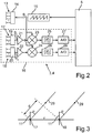
- the radars 3, 4 measure the respective target angle ⁇ 1 , ⁇ 2 according to the phase monopole method. Referring to the FIGS. 2 and 3 Now, the structure of a single radar device 3, 4, as well as the determination of a target angle ⁇ is explained in more detail.
- Fig. 2 2 shows a block diagram of a single radar 3, 4 and the control device 5.
- the radar 3, 4 comprises a transmitting antenna unit 13, which may be a single antenna or an array of antennas, which is fed via a feed circuit 14.
- the transmitting antenna unit 13 is using a supplied to local oscillator 15, which generates a transmission signal S 0 .
- This transmission signal S 0 is a frequency-modulated electromagnetic wave whose frequency has a sawtooth-shaped course in the exemplary embodiment. So the transmission signal S 0 is frequency-modulated; its frequency is periodically between a first value of, for example, 23.8 GHz and a second value of, for example, 24.2 GHz.
- the mean frequency of the transmission signal S 0 is 24 GHz in the exemplary embodiment.
- the local oscillator 15 is driven by the control device 5.
- the oscillator 15 is, for example, a voltage-controlled oscillator which generates the transmission signal S 0 at a frequency which is dependent on the amplitude of a DC voltage provided by the control device 5 to the oscillator 15.
- the radar device 3, 4 also comprises a receiver 16.
- the receiver 16 comprises two receiving antenna units 17, 18 which in the exemplary embodiment are each formed by a row of patch antennas.
- the receiving antenna units 17, 18 are each coupled to a feed circuit 19, 20.
- the supply circuits 19, 20 each provide a signal S 1 , S 2 , which are received signals.
- the received signals S 1 , S 2 are amplified by means of a respective low-noise amplifier 21, 22 (low noise amplifier), mixed down by means of a respective mixer 23, 24, low pass filtered by means of a respective low-pass filter 25, 26 and by means of an analogue amplifier.
- Digital converter 27, 28 analog-digital-converted.
- the transmission signal S 0 is used; the transmission signal S 0 is fed to the mixers 23, 24, for example by means of a directional coupler.
- the received digital signals S 1 , S 2 are then processed by means of the control device 5. From the signals 5 1 , S 2 , the control device 5 determines the distance R 1 , R 2 , the relative speed of the object 10, as well as the target angle ⁇ 1 , ⁇ 2 . In the present case, the interest is directed in particular to the determination of the target angle ⁇ 1 , ⁇ 2 .
- Fig. 3 shows the two receiving antenna units 17, 18 of the radar 3, 4 and an incident direction 29 of an incident electromagnetic wave.
- the target angle ⁇ is here the angle of incidence the electromagnetic wave, that is, the reference line 11 is parallel to the main beam direction of the receiving antenna units 17, 18.
- the wave first reaches the second receiving antenna unit 18 before arriving at the first receiving antenna unit 17.
- the difference between the propagation paths is d.
- a distance r between the two receiving antenna units 17, 18 is smaller than the wavelength of the electromagnetic wave.
- the control device 5 can detect the phase difference between the phases of the received signals S 1 , S 2 .
- a target angle parameter characteristic is stored in the control device 5, which reproduces the dependence of the phase difference of the target angle ⁇ . It can be stored in the control device 5 for the two radars 3, 4 separate target angle parameter characteristics. For the sake of simplicity, only a single target angle parameter characteristic for a radar 3, 4 will be considered below.
- Such an exemplary characteristic I is in Fig. 4 displayed.
- a phase difference ⁇ is plotted between the phases of the received signals S 1 , S 2 .
- the target angle ⁇ is plotted on the X axis.
- the target angle parameter characteristic I has the form of a sine function. In Fig. 4 is only a range of values of the target angle ⁇ from 0 ° to 90 °, so only a quarter of an entire period of the sine function shown. The relationship holds that the larger the target angle ⁇ is, the larger the phase difference ⁇ is.
- the radars 3, 4 are arranged in the embodiment behind the bumper of the motor vehicle 1. Installation tolerances, high-frequency properties and the shape of the bumper change the directivity of the receiving antenna units 17, 18, as well as the transmitting antenna unit 13. This falsifies the in Fig. 4 shown target angle parameter characteristic I. In addition, this characteristic I can change over the life of the motor vehicle 1. This happens, for example, by deformation of the bumper, deposition of dirt or aging of the components. The control device 5 counteracts this problem by correcting or calibrating the target angle parameter characteristic curve I.
- the control device 5 detects the distances R 1 , R 2 of an object 10 to the respective radar device 3, 4. If an object 10 is located in the overlapping area 9, it is possible to calculate the target angle ⁇ , namely after Trilaterationshabilit depending on the distance R 1 of the object 10 to the first radar device 3 and the distance R 2 of the same object 10 to the second radar device 4. If the control device 5 measures a phase difference of ⁇ 1 , the result is a target angle ⁇ of about 60 ° ( Fig. 4 ). At the same time, the control device 5 calculates the target angle ⁇ according to the trilateration method as a function of the distance R 1 , R 2 of the object 10 to the first radar 3 and to the second radar 4.
- This calculated target angle ⁇ coincides with the value of the target angle ⁇ in the target angle parameter Characteristic I does not match, as in Fig. 4 designated 30.
- it depends on a very accurate distance measurement. The smaller the distance between the radars 3, 4, the smaller the difference of the distance as a function of the target angle ⁇ and the more accurate the individual measurement of the distance R 1 , R 2 must be made. If the radar devices 3, 4 are arranged, for example, at a distance of 1.8 m from one another, a relatively small distance measuring error results in a relatively large angle error. For this reason, the trilateration method alone is not sufficient to accurately determine the target angle ⁇ .
- the ranging error and thus the error in the calculation of the target angle ⁇ after the trilateration method is a random error and not a systematic error, as is the case with the phase monopulse measurement.
- the error in the trilateration method can be considered approximately as mean free. In other words, the values calculated by the trilateration method for the target angle ⁇ are unbiased.
- a plurality of values calculated by the trilateration method are thus collected. This is in Fig. 4 for the target angle ⁇ of 60 ° shown schematically.
- a difference between the value of the target angle ⁇ in the target angle parameter characteristic I - in the case 60 ° - and the values calculated according to the trilateration method is calculated as a correction value.
- This correction value can be regarded as an estimate of the deviation of the target angle parameter characteristic I.
- the values calculated by the trilateration method are very noisy, so that the correction values are correspondingly noisy. For this reason, the correction values are averaged, and the value of the target angle ⁇ in the target angle parameter characteristic I is corrected by this mean value.
- a multiplicity, for example thousand, of correction values for each point in the target angle parameter characteristic curve I or for each target angular value in the characteristic curve I can first be collected. If all correction values are available, they are averaged, and the corresponding target angle value in the characteristic curve I is corrected by the mean value.
- the process of correcting alone can be effected even in a parked vehicle 1.
- a recursive filter can be used in the control device 5. Such a filter then calculates a moving average from the correction values.
- the target angle parameter characteristic I originally stored as reference is continuously corrected; the corresponding target angle value in the characteristic curve I is corrected by the current mean value of the moving average.
- the corresponding target angle value on the characteristic curve I is corrected by the calculated mean value from the correction values. It can be provided that the target angle value in the characteristic curve I is corrected at any mean value, namely even at a very low mean value. Then, each, even a small deviation of the target angle parameter characteristic I is corrected. However, to minimize the computational effort, a tolerance interval for the calculated mean can be defined. If the calculated mean value lies within this tolerance interval, then the target angle value in the characteristic curve I is not corrected. Only then, when the mean value leaves the tolerance interval, the correction of the target angle value in the target angle parameter characteristic curve is performed. Such a tolerance interval may be, for example, an angle range of -0.5 ° to + 0.5 °.
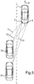
- the collection of target angle values calculated by the trilateration method will now be referred to an in Fig. 5 shown traffic situation on a highway explained in more detail.
- the motor vehicle 1, which has the radars 3, 4, travels in the right lane in a direction of travel designated 31.
- Another motor vehicle 32 runs on the left lane at a speed greater than that of the motor vehicle 1 Fig. 5 is the other motor vehicle 32 at two different times in two different positions, that is shown in two different distances to the motor vehicle 1.
- Now correction values for the target angle parameter characteristic I of the first radar device 3 are to be collected, namely by means of the trilateration method. In a time interval between the times at which the further motor vehicle 32 in the in Fig.
- a plurality of values for the target angle ⁇ are calculated by the trilateration method.
- the two positions of the further motor vehicle 32 correspond in the target angle parameter characteristic I according to FIG Fig. 4 a target angle of about 45 ° or 30 °. These points are in the target angle parameter characteristic I in Fig. 4 denoted by 33.
- the target angle ⁇ is calculated according to the trilateration method, namely to each point in the target angle parameter characteristic I between the points 33.
- one hundred values for the target angle can be calculated according to the trilateration method;
- Each value calculated according to the trilateration method for the target angle is in each case assigned to a value of the target angle ⁇ in the target angle parameter characteristic I.
- This is in Fig. 4 indicated schematically between the points 33.
- a multiplicity of values calculated according to the trilateration method to a single value of the target angle ⁇ in the target angle parameter characteristic curve I, a large number of objects are therefore required.
- a driver assistance device 2 is provided with which a precise determination of the target angle ⁇ is ensured.
- the target angle parameter characteristic I stored in the control device 5 is calibrated as a function of values obtained by the trilateration method for the target angle ⁇ .
- the angle measurement according to the phase monopole method has a small variance, but has systematic errors, namely, in particular due to a mounting angle and the distortion of the target angle parameter characteristic I by the bumper.
- the difference between the target angle according to the target angle parameter characteristic I and the target angle calculated by the trilateration method can be regarded as an estimate of the deviation of the target angle in the target angle parameter characteristic I. Since this estimate is very noisy due to high rangefinding errors, averaging the estimates can provide a precise estimate. In this way, it is possible to obtain a precise target angle parameter characteristic I.
Landscapes
- Engineering & Computer Science (AREA)
- Radar, Positioning & Navigation (AREA)
- Remote Sensing (AREA)
- Physics & Mathematics (AREA)
- Computer Networks & Wireless Communication (AREA)
- General Physics & Mathematics (AREA)
- Electromagnetism (AREA)
- Radar Systems Or Details Thereof (AREA)
Claims (8)
- Dispositif d'assistance au conducteur (2) destiné à déterminer un angle cible (α) d'un objet (10, 32) extérieur au dispositif, dans lequel l'angle cible (α) est un angle formé entre une ligne de référence (11) passant par un appareil radar (3) du dispositif d'assistance au conducteur (2) et une ligne de liaison (12) passant par l'appareil radar (3) et l'objet (10, 32), comportant- l'appareil radar (3), qui comprend au moins deux unités d'antenne de réception (17, 18) chacune destinée à recevoir des signaux (S1, S2),- un dispositif de commande (5) conçu pour déterminer, en fonction d'un paramètre (ϕ) lié aux signaux reçus (S1, S2), une valeur de l'angle cible (α) conformément à une courbe caractéristique du paramètre d'angle cible (I) stockée, et une valeur d'une distance (R1) de l'objet (10, 32) par rapport à l'appareil radar (3), dans lequel le paramètre (ϕ) est une différence de phase (ϕ) entre les phases des signaux reçus (S1, S2) et la courbe caractéristique du paramètre d'angle cible (I) représente la dépendance de la différence de phase (ϕ) par rapport à l'angle cible (α), et- un capteur (4) disposé de manière espacée de l'appareil radar (3), destiné à mesurer une distance (R2) de l'objet (10, 32) par rapport au même capteur (4),caractérisé en ce que le dispositif de commande (5) est conçu pour calculer l'angle cible (α) à partir de valeurs de mesure de la distance (R2) de l'objet (10, 32) par rapport au capteur (4) et des valeurs de la distance (R1) de l'objet (10, 32) par rapport à l'appareil radar (3) conformément à un procédé de calcul et pour corriger la courbe caractéristique du paramètre d'angle cible (I) stockée en fonction du résultat dudit calcul,
en ce qu'une pluralité de valeurs résultant de mesures individuelles effectuées sur différents objets et calculées par le procédé de calcul est associée à une valeur déterminée de l'angle cible (α) dans la courbe caractéristique du paramètre d'angle cible (I),
en ce que la pluralité des valeurs calculées conformément au procédé de calcul est moyennée et en ce que la valeur de l'angle cible (α) dans la courbe caractéristique du paramètre d'angle cible est corrigée en fonction de la valeur moyennée calculée. - Dispositif d'assistance au conducteur (2) selon la revendication 1, caractérisé en ce que le procédé de calcul est un procédé de trilatération.
- Dispositif d'assistance au conducteur (2) selon l'une des revendications précédentes, caractérisé en ce que le dispositif de commande (5) est conçu pour calculer une différence à partir de la valeur de l'angle cible (α) dans la courbe caractéristique du paramètre d'angle cible (I) et de la valeur calculée en tant que valeur de correction et pour corriger la valeur de l'angle cible (α) dans la courbe caractéristique du paramètre d'angle cible (I) en fonction de ladite valeur de correction.
- Dispositif d'assistance au conducteur (2) selon l'une des revendications précédentes, caractérisé en ce que l'appareil radar (3) est conçu pour émettre une onde électromagnétique continument modulée en fréquence (S0).
- Dispositif d'assistance au conducteur (2) selon l'une des revendications précédentes, caractérisé en ce que le capteur (4) séparé de l'appareil radar (3) est également un appareil radar, en particulier un appareil radar (3, 4) identique.
- Dispositif d'assistance au conducteur (2) selon la revendication 5, caractérisé en ce qu'une courbe caractéristique du paramètre d'angle cible (I) distincte est également stockée dans le dispositif de commande (5) pour le capteur séparé (4), et en ce que le dispositif de commande (5) est conçu pour corriger ladite courbe caractéristique du paramètre d'angle cible (I) en fonction de l'angle cible (α) calculé par le procédé de calcul.
- Véhicule automobile équipé d'un dispositif d'assistance au conducteur (2) selon l'une des revendications précédentes.
- Procédé de correction d'une courbe caractéristique d'un paramètre d'angle cible (I) stockée dans un dispositif de commande (5) d'un dispositif d'assistance au conducteur (2) et qui représente la dépendance d'un angle cible (α) d'un objet (10, 32) extérieur au dispositif et d'un paramètre (ϕ) relatif aux signaux reçus (S1, S2) par au moins deux unités d'antennes de réception (17, 18) d'un appareil radar (3) intérieur au dispositif de commande, dans lequel l'angle cible (α) est un angle formé entre une ligne de référence (11) passant par l'appareil radar (3) et une ligne de liaison (12) passant par l'appareil radar (3) et l'objet (10, 32), et le paramètre (ϕ) est une différence de phase (ϕ) entre les phases des signaux reçus (S1, S2) et la courbe caractéristique du paramètre d'angle cible (I) représente la dépendance de la différence de phase (ϕ) par rapport à l'angle cible (α), caractérisé par les étapes consistant à :a) mesurer une distance (R1) de l'objet (10, 32) par rapport à l'appareil radar (3),b) mesurer une distance (R2) de l'objet (10, 32) par rapport à un capteur (4) disposé de manière espacée de l'appareil radar (3),c) calculer l'angle cible (α) à partir des valeurs de mesure conformément aux étapes a) et b) selon un procédé de calcul etd) corriger la courbe caractéristique du paramètre d'angle cible (I) stockée en fonction du résultat du calcul,dans lequel une pluralité de valeurs résultant de mesures individuelles effectuées sur différents objets et calculées par le procédé de calcul est associée à une valeur déterminée de l'angle cible (α) dans la courbe caractéristique du paramètre d'angle cible (I), et la pluralité des valeurs calculées conformément au procédé de calcul est moyennée, et en ce que la valeur de l'angle cible (α) dans la courbe caractéristique du paramètre d'angle cible est corrigée en fonction de la valeur moyennée calculée.
Applications Claiming Priority (2)
| Application Number | Priority Date | Filing Date | Title |
|---|---|---|---|
| DE102009024064A DE102009024064A1 (de) | 2009-06-05 | 2009-06-05 | Fahrerassistenzeinrichtung zum Bestimmen eines Zielwinkels eines einrichtungsexternen Objektes und Verfahren zum Korrigieren einer Zielwinkel-Parameter-Kennlinie |
| PCT/EP2010/003303 WO2010139446A1 (fr) | 2009-06-05 | 2010-06-01 | Dispositif d'assistance de conducteur et procédé pour corriger une courbe caractéristique angle cible - paramètre |
Publications (2)
| Publication Number | Publication Date |
|---|---|
| EP2438460A1 EP2438460A1 (fr) | 2012-04-11 |
| EP2438460B1 true EP2438460B1 (fr) | 2019-04-10 |
Family
ID=42735310
Family Applications (1)
| Application Number | Title | Priority Date | Filing Date |
|---|---|---|---|
| EP10725025.0A Active EP2438460B1 (fr) | 2009-06-05 | 2010-06-01 | Dispositif d'assistance de conducteur et procédé pour corriger une courbe caractéristique angle cible - paramètre |
Country Status (3)
| Country | Link |
|---|---|
| EP (1) | EP2438460B1 (fr) |
| DE (1) | DE102009024064A1 (fr) |
| WO (1) | WO2010139446A1 (fr) |
Families Citing this family (8)
| Publication number | Priority date | Publication date | Assignee | Title |
|---|---|---|---|---|
| DE102011015935A1 (de) | 2011-04-02 | 2012-10-04 | Valeo Schalter Und Sensoren Gmbh | Verfahren zum Bestimmen eines Korrekturwerts für die Messung eines Zielwinkels mit einem Radargerät, Fahrerassistenzsystem und Kraftfahrzeug |
| DE102012101303A1 (de) * | 2012-02-17 | 2013-08-22 | Hella Kgaa Hueck & Co. | Sensorvorrichtung |
| DE102012101363A1 (de) * | 2012-02-21 | 2013-08-22 | Hella Kgaa Hueck & Co. | Verfahren zum Betreiben einer Schaltungsanordnung mit einem Steuer- und/oder Regelungsmittel für ein Leuchtdiodenfeld |
| JP6168784B2 (ja) * | 2013-02-08 | 2017-07-26 | 古河電気工業株式会社 | 周辺監視システム及び周辺監視システムの軸ずれ検知方法 |
| DE102013203574A1 (de) | 2013-03-01 | 2014-09-04 | Hella Kgaa Hueck & Co. | Verfahren zur Kompensation von Winkelmessfehlern |
| DE102015119660A1 (de) * | 2015-11-13 | 2017-05-18 | Valeo Schalter Und Sensoren Gmbh | Verfahren zum Kalibrieren eines Sensors eines Kraftfahrzeugs zur Winkelmessung, Recheneinrichtung, Fahrerassistenzsystem sowie Kraftfahrzeug |
| JP6859073B2 (ja) * | 2016-11-01 | 2021-04-14 | 株式会社デンソー | 異常検出装置 |
| JP6848725B2 (ja) * | 2017-06-29 | 2021-03-24 | 株式会社デンソー | 車両用の対象物検出装置および車両用の対象物検出装置における水平方向の軸ずれ判定方法 |
Family Cites Families (6)
| Publication number | Priority date | Publication date | Assignee | Title |
|---|---|---|---|---|
| JPH09191213A (ja) * | 1995-11-07 | 1997-07-22 | Denso Corp | 開口面アンテナ |
| DE10149115A1 (de) * | 2001-10-05 | 2003-04-17 | Bosch Gmbh Robert | Objekterfassungsvorrichtung |
| DE10241456A1 (de) * | 2002-09-07 | 2004-03-18 | Robert Bosch Gmbh | Sensoranordnung und Verfahren zur Abstandsregelung bei Kraftfahrzeugen |
| DE10357148A1 (de) * | 2003-12-06 | 2005-07-07 | Robert Bosch Gmbh | Radarsensor |
| DE102004017268A1 (de) * | 2004-04-07 | 2005-11-03 | Siemens Ag | Verfahren und Anordnung zur Positionsbestimmung eines Objekts |
| DE102005015259A1 (de) * | 2005-04-04 | 2006-10-12 | Robert Bosch Gmbh | Verfahren und Vorrichtung zur Positionsbestimmung von Objekten |
-
2009
- 2009-06-05 DE DE102009024064A patent/DE102009024064A1/de not_active Withdrawn
-
2010
- 2010-06-01 WO PCT/EP2010/003303 patent/WO2010139446A1/fr active Application Filing
- 2010-06-01 EP EP10725025.0A patent/EP2438460B1/fr active Active
Non-Patent Citations (1)
| Title |
|---|
| None * |
Also Published As
| Publication number | Publication date |
|---|---|
| EP2438460A1 (fr) | 2012-04-11 |
| DE102009024064A1 (de) | 2010-12-09 |
| WO2010139446A1 (fr) | 2010-12-09 |
Similar Documents
| Publication | Publication Date | Title |
|---|---|---|
| EP2438460B1 (fr) | Dispositif d'assistance de conducteur et procédé pour corriger une courbe caractéristique angle cible - paramètre | |
| DE102018207718A1 (de) | Verfahren zur Phasenkalibrierung von Hochfrequenzbausteinen eines Radarsensors | |
| EP2507649B1 (fr) | Procédé de détermination univoque d'une distance et/ou d'une vitesse relative d'un objet, système d'assistance au conducteur et véhicule à moteur | |
| DE102011015935A1 (de) | Verfahren zum Bestimmen eines Korrekturwerts für die Messung eines Zielwinkels mit einem Radargerät, Fahrerassistenzsystem und Kraftfahrzeug | |
| EP3143712B1 (fr) | Procédé d'étalonnage d'un capteur radar mimo pour véhicules automobiles | |
| DE102018132745B4 (de) | Fmcw radar mit störsignalunterdrückung im zeitbereich | |
| EP3204788B1 (fr) | Capteur radar formeur d'image avec formation numérique horizontale de faisceau et mesure verticale d'objet par comparaison de phases en cas d'émetteurs décalés les uns par rapport aux autres | |
| EP1395846B1 (fr) | Procede et dispositif pour l'auto-etalonnage d'un ensemble de capteurs radar | |
| WO2017080791A1 (fr) | Procédé d'étalonnage d'un capteur d'un véhicule automobile pour une mesure d'angle, dispositif informatique, système d'assistance à la conduite ainsi que véhicule automobile | |
| DE102018210070A1 (de) | Verfahren zur Kalibrierung eines MIMO-Radarsensors für Kraftfahrzeuge | |
| EP3752858B1 (fr) | Capteur radar à large bande à résolution angulaire pour véhicules automobiles | |
| DE102009032124A1 (de) | Verfahren zum Erkennen eines blockierten Zustands eines Radargeräts und Fahrerassistenzeinrichtung | |
| DE102012021212A1 (de) | Verfahren zur Detektion einer Interferenz in einem Empfangssignal eines Radarsensors, Fahrerassistenzeinrichtung und Kraftfahrzeug | |
| EP3060942B1 (fr) | Procédé pour la détermination de la disposition d'au moins deux capteurs et réseaux de capteurs | |
| WO2013117276A1 (fr) | Capteur radar | |
| WO2011117173A1 (fr) | Dispositif d'assistance au conducteur pour un véhicule et procédé pour faire fonctionner un appareil radar | |
| DE102012024998A1 (de) | Verfahren zum Bestimmen einer lateralen Geschwindigkeit eines Zielobjekts relativ zu einem Kraftfahrzeug mit Hilfe eines Radarsensors, Fahrerassistenzsystem und Kraftfahrzeug | |
| DE102013203574A1 (de) | Verfahren zur Kompensation von Winkelmessfehlern | |
| DE102015208901A1 (de) | Radarsensor für Kraftfahrzeuge | |
| DE102020006220A1 (de) | Minimieren von Phasenrauschen in einem FMCW-Radar und Erkennen einer Radargehäusebeschichtung | |
| DE102015116434A1 (de) | Verfahren zur Schätzung der Eigengeschwindigkeit | |
| WO2019158253A1 (fr) | Estimation de vitesses transversales ou de vitesses cartésiennes de cibles ponctuelles au moyen d'un capteur radar | |
| DE102008043394A1 (de) | Verfahren zur Detektion von Peaküberlagerungen in einem diskreten Spektrum eines Ortungssignals | |
| EP3752852A1 (fr) | Estimation de vitesses cartésiennes d'objets radar étendus au moyen d'un capteur radar | |
| DE102018129876B3 (de) | Verfahren zum Bestimmen einer geometrischen Eigenschaft eines Objekts mittels einer Geradengleichung, Computerprogrammprodukt, elektronische Recheneinrichtung sowie Ultraschallsensorvorrichtung |
Legal Events
| Date | Code | Title | Description |
|---|---|---|---|
| PUAI | Public reference made under article 153(3) epc to a published international application that has entered the european phase |
Free format text: ORIGINAL CODE: 0009012 |
|
| 17P | Request for examination filed |
Effective date: 20111117 |
|
| AK | Designated contracting states |
Kind code of ref document: A1 Designated state(s): AL AT BE BG CH CY CZ DE DK EE ES FI FR GB GR HR HU IE IS IT LI LT LU LV MC MK MT NL NO PL PT RO SE SI SK SM TR |
|
| DAX | Request for extension of the european patent (deleted) | ||
| 17Q | First examination report despatched |
Effective date: 20160614 |
|
| STAA | Information on the status of an ep patent application or granted ep patent |
Free format text: STATUS: EXAMINATION IS IN PROGRESS |
|
| GRAP | Despatch of communication of intention to grant a patent |
Free format text: ORIGINAL CODE: EPIDOSNIGR1 |
|
| STAA | Information on the status of an ep patent application or granted ep patent |
Free format text: STATUS: GRANT OF PATENT IS INTENDED |
|
| RIC1 | Information provided on ipc code assigned before grant |
Ipc: G01S 13/48 20060101ALI20181026BHEP Ipc: G01S 13/93 20060101ALI20181026BHEP Ipc: G01S 13/46 20060101ALI20181026BHEP Ipc: G01S 13/58 20060101ALI20181026BHEP Ipc: G01S 13/87 20060101ALI20181026BHEP Ipc: G01S 5/14 20060101ALI20181026BHEP Ipc: G01S 13/44 20060101ALI20181026BHEP Ipc: G01S 5/02 20100101ALI20181026BHEP Ipc: G01S 7/40 20060101AFI20181026BHEP |
|
| INTG | Intention to grant announced |
Effective date: 20181203 |
|
| GRAS | Grant fee paid |
Free format text: ORIGINAL CODE: EPIDOSNIGR3 |
|
| GRAA | (expected) grant |
Free format text: ORIGINAL CODE: 0009210 |
|
| STAA | Information on the status of an ep patent application or granted ep patent |
Free format text: STATUS: THE PATENT HAS BEEN GRANTED |
|
| AK | Designated contracting states |
Kind code of ref document: B1 Designated state(s): AL AT BE BG CH CY CZ DE DK EE ES FI FR GB GR HR HU IE IS IT LI LT LU LV MC MK MT NL NO PL PT RO SE SI SK SM TR |
|
| REG | Reference to a national code |
Ref country code: GB Ref legal event code: FG4D Free format text: NOT ENGLISH |
|
| REG | Reference to a national code |
Ref country code: CH Ref legal event code: EP Ref country code: AT Ref legal event code: REF Ref document number: 1119459 Country of ref document: AT Kind code of ref document: T Effective date: 20190415 |
|
| REG | Reference to a national code |
Ref country code: IE Ref legal event code: FG4D Free format text: LANGUAGE OF EP DOCUMENT: GERMAN |
|
| REG | Reference to a national code |
Ref country code: DE Ref legal event code: R096 Ref document number: 502010015930 Country of ref document: DE |
|
| REG | Reference to a national code |
Ref country code: NL Ref legal event code: MP Effective date: 20190410 |
|
| REG | Reference to a national code |
Ref country code: LT Ref legal event code: MG4D |
|
| PG25 | Lapsed in a contracting state [announced via postgrant information from national office to epo] |
Ref country code: NL Free format text: LAPSE BECAUSE OF FAILURE TO SUBMIT A TRANSLATION OF THE DESCRIPTION OR TO PAY THE FEE WITHIN THE PRESCRIBED TIME-LIMIT Effective date: 20190410 |
|
| PG25 | Lapsed in a contracting state [announced via postgrant information from national office to epo] |
Ref country code: PT Free format text: LAPSE BECAUSE OF FAILURE TO SUBMIT A TRANSLATION OF THE DESCRIPTION OR TO PAY THE FEE WITHIN THE PRESCRIBED TIME-LIMIT Effective date: 20190910 Ref country code: HR Free format text: LAPSE BECAUSE OF FAILURE TO SUBMIT A TRANSLATION OF THE DESCRIPTION OR TO PAY THE FEE WITHIN THE PRESCRIBED TIME-LIMIT Effective date: 20190410 Ref country code: NO Free format text: LAPSE BECAUSE OF FAILURE TO SUBMIT A TRANSLATION OF THE DESCRIPTION OR TO PAY THE FEE WITHIN THE PRESCRIBED TIME-LIMIT Effective date: 20190710 Ref country code: SE Free format text: LAPSE BECAUSE OF FAILURE TO SUBMIT A TRANSLATION OF THE DESCRIPTION OR TO PAY THE FEE WITHIN THE PRESCRIBED TIME-LIMIT Effective date: 20190410 Ref country code: FI Free format text: LAPSE BECAUSE OF FAILURE TO SUBMIT A TRANSLATION OF THE DESCRIPTION OR TO PAY THE FEE WITHIN THE PRESCRIBED TIME-LIMIT Effective date: 20190410 Ref country code: AL Free format text: LAPSE BECAUSE OF FAILURE TO SUBMIT A TRANSLATION OF THE DESCRIPTION OR TO PAY THE FEE WITHIN THE PRESCRIBED TIME-LIMIT Effective date: 20190410 Ref country code: LT Free format text: LAPSE BECAUSE OF FAILURE TO SUBMIT A TRANSLATION OF THE DESCRIPTION OR TO PAY THE FEE WITHIN THE PRESCRIBED TIME-LIMIT Effective date: 20190410 Ref country code: ES Free format text: LAPSE BECAUSE OF FAILURE TO SUBMIT A TRANSLATION OF THE DESCRIPTION OR TO PAY THE FEE WITHIN THE PRESCRIBED TIME-LIMIT Effective date: 20190410 |
|
| PG25 | Lapsed in a contracting state [announced via postgrant information from national office to epo] |
Ref country code: BG Free format text: LAPSE BECAUSE OF FAILURE TO SUBMIT A TRANSLATION OF THE DESCRIPTION OR TO PAY THE FEE WITHIN THE PRESCRIBED TIME-LIMIT Effective date: 20190710 Ref country code: PL Free format text: LAPSE BECAUSE OF FAILURE TO SUBMIT A TRANSLATION OF THE DESCRIPTION OR TO PAY THE FEE WITHIN THE PRESCRIBED TIME-LIMIT Effective date: 20190410 Ref country code: GR Free format text: LAPSE BECAUSE OF FAILURE TO SUBMIT A TRANSLATION OF THE DESCRIPTION OR TO PAY THE FEE WITHIN THE PRESCRIBED TIME-LIMIT Effective date: 20190711 Ref country code: LV Free format text: LAPSE BECAUSE OF FAILURE TO SUBMIT A TRANSLATION OF THE DESCRIPTION OR TO PAY THE FEE WITHIN THE PRESCRIBED TIME-LIMIT Effective date: 20190410 |
|
| PG25 | Lapsed in a contracting state [announced via postgrant information from national office to epo] |
Ref country code: IS Free format text: LAPSE BECAUSE OF FAILURE TO SUBMIT A TRANSLATION OF THE DESCRIPTION OR TO PAY THE FEE WITHIN THE PRESCRIBED TIME-LIMIT Effective date: 20190810 |
|
| REG | Reference to a national code |
Ref country code: DE Ref legal event code: R097 Ref document number: 502010015930 Country of ref document: DE |
|
| PG25 | Lapsed in a contracting state [announced via postgrant information from national office to epo] |
Ref country code: DK Free format text: LAPSE BECAUSE OF FAILURE TO SUBMIT A TRANSLATION OF THE DESCRIPTION OR TO PAY THE FEE WITHIN THE PRESCRIBED TIME-LIMIT Effective date: 20190410 Ref country code: RO Free format text: LAPSE BECAUSE OF FAILURE TO SUBMIT A TRANSLATION OF THE DESCRIPTION OR TO PAY THE FEE WITHIN THE PRESCRIBED TIME-LIMIT Effective date: 20190410 Ref country code: EE Free format text: LAPSE BECAUSE OF FAILURE TO SUBMIT A TRANSLATION OF THE DESCRIPTION OR TO PAY THE FEE WITHIN THE PRESCRIBED TIME-LIMIT Effective date: 20190410 Ref country code: MC Free format text: LAPSE BECAUSE OF FAILURE TO SUBMIT A TRANSLATION OF THE DESCRIPTION OR TO PAY THE FEE WITHIN THE PRESCRIBED TIME-LIMIT Effective date: 20190410 Ref country code: CZ Free format text: LAPSE BECAUSE OF FAILURE TO SUBMIT A TRANSLATION OF THE DESCRIPTION OR TO PAY THE FEE WITHIN THE PRESCRIBED TIME-LIMIT Effective date: 20190410 Ref country code: SK Free format text: LAPSE BECAUSE OF FAILURE TO SUBMIT A TRANSLATION OF THE DESCRIPTION OR TO PAY THE FEE WITHIN THE PRESCRIBED TIME-LIMIT Effective date: 20190410 |
|
| REG | Reference to a national code |
Ref country code: CH Ref legal event code: PL |
|
| PLBE | No opposition filed within time limit |
Free format text: ORIGINAL CODE: 0009261 |
|
| STAA | Information on the status of an ep patent application or granted ep patent |
Free format text: STATUS: NO OPPOSITION FILED WITHIN TIME LIMIT |
|
| PG25 | Lapsed in a contracting state [announced via postgrant information from national office to epo] |
Ref country code: SM Free format text: LAPSE BECAUSE OF FAILURE TO SUBMIT A TRANSLATION OF THE DESCRIPTION OR TO PAY THE FEE WITHIN THE PRESCRIBED TIME-LIMIT Effective date: 20190410 Ref country code: IT Free format text: LAPSE BECAUSE OF FAILURE TO SUBMIT A TRANSLATION OF THE DESCRIPTION OR TO PAY THE FEE WITHIN THE PRESCRIBED TIME-LIMIT Effective date: 20190410 |
|
| 26N | No opposition filed |
Effective date: 20200113 |
|
| REG | Reference to a national code |
Ref country code: BE Ref legal event code: MM Effective date: 20190630 |
|
| PG25 | Lapsed in a contracting state [announced via postgrant information from national office to epo] |
Ref country code: TR Free format text: LAPSE BECAUSE OF FAILURE TO SUBMIT A TRANSLATION OF THE DESCRIPTION OR TO PAY THE FEE WITHIN THE PRESCRIBED TIME-LIMIT Effective date: 20190410 |
|
| PG25 | Lapsed in a contracting state [announced via postgrant information from national office to epo] |
Ref country code: IE Free format text: LAPSE BECAUSE OF NON-PAYMENT OF DUE FEES Effective date: 20190601 |
|
| PG25 | Lapsed in a contracting state [announced via postgrant information from national office to epo] |
Ref country code: LI Free format text: LAPSE BECAUSE OF NON-PAYMENT OF DUE FEES Effective date: 20190630 Ref country code: CH Free format text: LAPSE BECAUSE OF NON-PAYMENT OF DUE FEES Effective date: 20190630 Ref country code: SI Free format text: LAPSE BECAUSE OF FAILURE TO SUBMIT A TRANSLATION OF THE DESCRIPTION OR TO PAY THE FEE WITHIN THE PRESCRIBED TIME-LIMIT Effective date: 20190410 Ref country code: LU Free format text: LAPSE BECAUSE OF NON-PAYMENT OF DUE FEES Effective date: 20190601 Ref country code: BE Free format text: LAPSE BECAUSE OF NON-PAYMENT OF DUE FEES Effective date: 20190630 |
|
| REG | Reference to a national code |
Ref country code: AT Ref legal event code: MM01 Ref document number: 1119459 Country of ref document: AT Kind code of ref document: T Effective date: 20190601 |
|
| PG25 | Lapsed in a contracting state [announced via postgrant information from national office to epo] |
Ref country code: AT Free format text: LAPSE BECAUSE OF NON-PAYMENT OF DUE FEES Effective date: 20190601 |
|
| PG25 | Lapsed in a contracting state [announced via postgrant information from national office to epo] |
Ref country code: CY Free format text: LAPSE BECAUSE OF FAILURE TO SUBMIT A TRANSLATION OF THE DESCRIPTION OR TO PAY THE FEE WITHIN THE PRESCRIBED TIME-LIMIT Effective date: 20190410 |
|
| PG25 | Lapsed in a contracting state [announced via postgrant information from national office to epo] |
Ref country code: MT Free format text: LAPSE BECAUSE OF FAILURE TO SUBMIT A TRANSLATION OF THE DESCRIPTION OR TO PAY THE FEE WITHIN THE PRESCRIBED TIME-LIMIT Effective date: 20190410 Ref country code: HU Free format text: LAPSE BECAUSE OF FAILURE TO SUBMIT A TRANSLATION OF THE DESCRIPTION OR TO PAY THE FEE WITHIN THE PRESCRIBED TIME-LIMIT; INVALID AB INITIO Effective date: 20100601 |
|
| PG25 | Lapsed in a contracting state [announced via postgrant information from national office to epo] |
Ref country code: MK Free format text: LAPSE BECAUSE OF FAILURE TO SUBMIT A TRANSLATION OF THE DESCRIPTION OR TO PAY THE FEE WITHIN THE PRESCRIBED TIME-LIMIT Effective date: 20190410 |
|
| P01 | Opt-out of the competence of the unified patent court (upc) registered |
Effective date: 20230528 |
|
| PGFP | Annual fee paid to national office [announced via postgrant information from national office to epo] |
Ref country code: GB Payment date: 20240626 Year of fee payment: 15 |
|
| PGFP | Annual fee paid to national office [announced via postgrant information from national office to epo] |
Ref country code: DE Payment date: 20240613 Year of fee payment: 15 |
|
| PGFP | Annual fee paid to national office [announced via postgrant information from national office to epo] |
Ref country code: FR Payment date: 20240625 Year of fee payment: 15 |