EP2438019B1 - Method for biological purification of waste water. - Google Patents
Method for biological purification of waste water. Download PDFInfo
- Publication number
- EP2438019B1 EP2438019B1 EP10783628.0A EP10783628A EP2438019B1 EP 2438019 B1 EP2438019 B1 EP 2438019B1 EP 10783628 A EP10783628 A EP 10783628A EP 2438019 B1 EP2438019 B1 EP 2438019B1
- Authority
- EP
- European Patent Office
- Prior art keywords
- reactor
- water
- sludge
- elements
- biofilm
- Prior art date
- Legal status (The legal status is an assumption and is not a legal conclusion. Google has not performed a legal analysis and makes no representation as to the accuracy of the status listed.)
- Active
Links
Images
Classifications
-
- C—CHEMISTRY; METALLURGY
- C02—TREATMENT OF WATER, WASTE WATER, SEWAGE, OR SLUDGE
- C02F—TREATMENT OF WATER, WASTE WATER, SEWAGE, OR SLUDGE
- C02F3/00—Biological treatment of water, waste water, or sewage
- C02F3/02—Aerobic processes
- C02F3/06—Aerobic processes using submerged filters
-
- B—PERFORMING OPERATIONS; TRANSPORTING
- B01—PHYSICAL OR CHEMICAL PROCESSES OR APPARATUS IN GENERAL
- B01D—SEPARATION
- B01D39/00—Filtering material for liquid or gaseous fluids
- B01D39/02—Loose filtering material, e.g. loose fibres
-
- B—PERFORMING OPERATIONS; TRANSPORTING
- B01—PHYSICAL OR CHEMICAL PROCESSES OR APPARATUS IN GENERAL
- B01J—CHEMICAL OR PHYSICAL PROCESSES, e.g. CATALYSIS OR COLLOID CHEMISTRY; THEIR RELEVANT APPARATUS
- B01J47/00—Ion-exchange processes in general; Apparatus therefor
-
- C—CHEMISTRY; METALLURGY
- C02—TREATMENT OF WATER, WASTE WATER, SEWAGE, OR SLUDGE
- C02F—TREATMENT OF WATER, WASTE WATER, SEWAGE, OR SLUDGE
- C02F1/00—Treatment of water, waste water, or sewage
- C02F1/42—Treatment of water, waste water, or sewage by ion-exchange
-
- C—CHEMISTRY; METALLURGY
- C02—TREATMENT OF WATER, WASTE WATER, SEWAGE, OR SLUDGE
- C02F—TREATMENT OF WATER, WASTE WATER, SEWAGE, OR SLUDGE
- C02F11/00—Treatment of sludge; Devices therefor
- C02F11/02—Biological treatment
-
- C—CHEMISTRY; METALLURGY
- C02—TREATMENT OF WATER, WASTE WATER, SEWAGE, OR SLUDGE
- C02F—TREATMENT OF WATER, WASTE WATER, SEWAGE, OR SLUDGE
- C02F3/00—Biological treatment of water, waste water, or sewage
- C02F3/02—Aerobic processes
- C02F3/10—Packings; Fillings; Grids
-
- C—CHEMISTRY; METALLURGY
- C02—TREATMENT OF WATER, WASTE WATER, SEWAGE, OR SLUDGE
- C02F—TREATMENT OF WATER, WASTE WATER, SEWAGE, OR SLUDGE
- C02F3/00—Biological treatment of water, waste water, or sewage
- C02F3/02—Aerobic processes
- C02F3/12—Activated sludge processes
- C02F3/1236—Particular type of activated sludge installations
- C02F3/1263—Sequencing batch reactors [SBR]
-
- C—CHEMISTRY; METALLURGY
- C02—TREATMENT OF WATER, WASTE WATER, SEWAGE, OR SLUDGE
- C02F—TREATMENT OF WATER, WASTE WATER, SEWAGE, OR SLUDGE
- C02F3/00—Biological treatment of water, waste water, or sewage
- C02F3/28—Anaerobic digestion processes
- C02F3/2826—Anaerobic digestion processes using anaerobic filters
-
- C—CHEMISTRY; METALLURGY
- C02—TREATMENT OF WATER, WASTE WATER, SEWAGE, OR SLUDGE
- C02F—TREATMENT OF WATER, WASTE WATER, SEWAGE, OR SLUDGE
- C02F3/00—Biological treatment of water, waste water, or sewage
- C02F3/28—Anaerobic digestion processes
- C02F3/2833—Anaerobic digestion processes using fluidized bed reactors
-
- Y—GENERAL TAGGING OF NEW TECHNOLOGICAL DEVELOPMENTS; GENERAL TAGGING OF CROSS-SECTIONAL TECHNOLOGIES SPANNING OVER SEVERAL SECTIONS OF THE IPC; TECHNICAL SUBJECTS COVERED BY FORMER USPC CROSS-REFERENCE ART COLLECTIONS [XRACs] AND DIGESTS
- Y02—TECHNOLOGIES OR APPLICATIONS FOR MITIGATION OR ADAPTATION AGAINST CLIMATE CHANGE
- Y02W—CLIMATE CHANGE MITIGATION TECHNOLOGIES RELATED TO WASTEWATER TREATMENT OR WASTE MANAGEMENT
- Y02W10/00—Technologies for wastewater treatment
- Y02W10/10—Biological treatment of water, waste water, or sewage
Definitions
- the present invention relates to a method for biological purification of water in a reactor with one or more inlet and outlet zones where water and substrate come into contact with carrier elements for a biofilm.
- the reactor can be arranged for aerobic, anaerobic and anoxic purification of municipal and industrial waste water, processing water, water from aquaculture installations and drinking water.
- the process is based on the principle that biomass is established on a carrier element for the formation of a biofilm.
- the carrier elements are held in place in the reactor with the help of an outlet arrangement.
- the degree of filling of the carrier elements in the reactor is so large that during normal operation they are not free to move -hindered movement. All known types of carrier elements, with a specific weight relatively near to the specific weight of water can be used.
- the invention will result in a better transfer of oxygen from the air blown into the water and a better transport of water and substrate to the biofilm, something which will result in a more compact and less energy demanding installation.
- Bio purification entails that a culture of micro-organisms carries out the desired transformation of the materials in the water. Biological purification is, to a large extent, combined with mechanical and chemical purification methods.
- Bio purification is much used for purification of polluted water. Traditionally, biological purification has been completely dominating for removal of organic materials and, for the last years, biological purification has also become dominating for the removal of nitrogen (nitrification, de-nitrification, anammox) and relatively common for removal of phosphorous (bio-P removal).
- aerobic processes In aerobic processes the micro-organisms need molecular oxygen as an electron acceptor.
- anoxic processes one depends on the absence of molecular oxygen and the micro-organisms will use nitrate or sulphate as the electron acceptor.
- biological removal of nitrogen one combines an aerobic process, which oxidises ammonium to nitrate, with an anoxic process that reduces nitrate to molecular nitrogen gas.
- Anaerobic processes take place in the absence of oxygen and are characterised in that the organic material in the water is both electron donor and electron acceptor. Anaerobic processes are most relevant for highly concentrated industrial discharge of organic matter and in a complete decomposition the end product will be a mixture of methane and carbon dioxide (biogas).
- the micro-organisms one needs for biological purification could, in principle, be suspended in the water phase in a bioreactor, or be attached to surfaces in the bioreactor.
- a process with suspended micro-organisms is called an activated sludge process.
- the micro-organisms in an activated sludge process must be able to form floccules that are separated from the water in a downstream reactor and are returned to the bioreactor.
- the suspended micro-organisms can be held in place in the bioreactor in that the purified water is drained from the reactor via membranes with pore openings so small that the micro-organisms are held back in the bioreactor. This is known as a membrane bioreactor (MBR) process.
- MLR membrane bioreactor
- a process where the micro-organisms are attached to a surface is called a biofilm process.
- biofilm processes used in purification of water are trickling filters, bio rotors, submerged biological filters, moving bed processes and fluidised bed processes.
- Submerged biological filters include both filters with a relatively open carrier medium of plastic and filters with a carrier medium of a small diameter (sand, Leca balls, small polystyrene balls). Submerged biological filters with a carrier medium of a small diameter will relatively quickly be clogged up with biosludge and must be regularly taken out of operation for backflushing and removal of the sludge.
- IFAS integrated fixed film and activated sludge
- the membrane bioreactor process is a relatively new technology where membranes with very small pore openings are used to separate the activated sludge from the water.
- MLR membrane bioreactor process
- This technology one can manage with considerably smaller reactor volumes than for a conventional activated sludge process, in that one can keep a considerably higher concentration of micro-organisms in the reactors.
- the purified water will be free of suspended matter.
- the disadvantages with this process are that it is still very costly, it requires much pre-treatment of the water to remove materials that can lead to clogging of the membranes, the membranes must be washed regularly to maintain the hydraulic capacity and the energy consumption is relatively high.
- trickling filters are the biofilm processes that were first taken into use for purification of waste water. Initially, trickling filters were filled with stone, but modern trickling filters are filled with plastic materials with a larger surface area for the biofilm to grow on. Modern trickling filters are relatively tall. The water is pumped to the top of the trickling filter and distributed evenly over the whole surface. The supply of oxygen takes place by natural ventilation. It is difficult to adjust the amount of water, load of matter and natural supply of oxygen in a trickling filter so that everything functions optimally. It is relatively common that the biofilm in the upper parts of a trickling filter does not get enough oxygen. Therefore, trickling filters have normally lower conversion rates and require larger reactor volumes than other biofilm processes.
- Bio rotors are biofilm processes that became very popular in the 1970's. The principle is that one has circular discs with corrugated surfaces secured to a horizontal shaft that rotates slowly in a basin. The discs are partially submerged in the water and a biofilm is established on the discs which alternatively take up polluting material from the water phase and oxygen from the air when the discs rotate.
- a big disadvantage with the bio rotor systems is that they are based on prefabricated rotors that make the system not very flexible. All basins must be adapted to the dimensions of the bio rotor.
- Submerged biological filters with a relatively open biofilm medium use, in principle, the same type of plastic material as modern trickle filters.
- the plastic material is stationary, submerged in the reactor and oxygen is supplied via diffuser aerators at the bottom of the reactor.
- a problem with submerged bio filters of this type has been clogging from growth of biomass and formation of channels. Water and air take the path of least resistance and zones are formed in aerated reactors where the biomass is accumulated resulting in anaerobic conditions.
- Another disadvantage is that one has no access to the aerators below the stationary biofilm medium. For maintenance or replacing of the aerators one must first remove the biofilm medium from the reactor.
- Submerged biological filters with a carrier medium of a small diameter have a very large biofilm surface area.
- the carrier medium is stationary during normal operation, but this type of filter will clog up with bio sludge and must regularly be taken out of operation for backflushing and removal of sludge.
- the process is sensitive to particles in the waste water and for waste waters with much suspended matter the operation cycles between each flushing become very short. Because of fittings for flushing and placing of the aerator at the bottom of the reactors, these types of biofilm reactors are complicated to construct.
- a common designation for this type of biofilm reactor is BAF (biological aerated filter) and the best known brand names are Biostyr, Biocarbone and Biofor.
- the biofilm grows on a carrier material that floats freely around in the reactor.
- the carrier material has either been foam rubber or small elements of plastic. Processes that use foam rubber pieces are known by the name Captor and Linpor.
- Captor and Linpor Processes that use foam rubber pieces are known by the name Captor and Linpor.
- the disadvantages with foam rubber pieces are that the effective biofilm area is too small because the growth on the outside of the foam rubber pieces clogs up the pores and prevents ingress of substrate and oxygen to the inner parts of the foam rubber pieces.
- the carrier material is small pieces of plastic.
- the pieces of plastic are normally distributed evenly in the whole of the water volume and in practice one operates with degrees of filling with biofilm medium up to about 67 %. Sieves keep the plastic pieces in place in the reactor.
- the reactors are operated continuously without the need for back flushing.
- the patent NO 172687 B3 describes that one operates with 30 to 70 % degree of filling and the particles move freely.
- the carriers shall have a specific weight of 0.90 - 1.20.
- the patent also states that one has mixing appliances to ensure a good mixing of the reactor content.
- the biofilm grows on small grains of sand.
- the operating principle is based on water being pumped into the bottom of the reactor at such a high rate that the sand is fluidised.
- Normally water is recirculated many times to get the rate of flow high enough to fluidise the sand and one supplies oxygen by saturating the recirculated stream of water with air or pure oxygen.
- the pumping costs can be large.
- In full scale plants one has the problem of distributing the water in such a way that the whole of the sand bed fluidises.
- WO2006114552 discloses a fluidised bed reactor with carriers for a biofilm.
- the carriers occupy between 40-80% of the reactor fill volume.
- Carriers are alternatively fluidised for sludge removal by activating a mixer and a pump for air.
- the present invention is comprised of a biofilm process where the growth surface for micro-organisms consists of carrier elements that are packed so closely that they can not move freely in normal operation, but they have no, or a hindered, movement.
- the ideal carrier elements have a large protected surface area and a large pore volume so that the water can flow through the carrier elements and ensure good contact between water, substrate and biofilm. All known types of carrier elements with a specific weight relatively near the specific weight of water can be used.
- the degree of filling of carrier elements is greater than in moving bed processes. Because of increased degree of filling and thus no, or a hindered, movement of the carrier elements, the velocity gradient between the biofilm and water will increase. Thus, the thickness of the stationary layer of water above the biofilm is reduced, the resistance to diffusion is reduced, the transport of substrate and oxygen is improved and the rate of conversion is increased. It is desirable that the biofilm elements have a large pore volume so that they can store as much sludge as possible on and in the biofilm elements before excess sludge must be washed out of the reactor. Thus, one can get long operating periods between each washing.
- a reactor for biological purification of water is known from CN 100337936C .
- the reactor contains carrier elements for a biofilm and these elements have a specific weight of 0.7-0.95 and the degree of filling for the elements is 20-90% of the effective volume of the reactor.
- a method and a reactor for purification of water are known.
- the water is fed into the reactor which is filled with the carriers for the biofilm.
- These carriers have a specific weight in the area 0.90 - 1.20 kg/dm 3 and a degree of filling for the carriers of 30-70 % of the reactor volume.
- the reactor has mixing equipment and also appliances in the form of a sieve plate to retain the carriers in the reactor.
- NO 314255 describes an application of carrier elements in connection with the purification of water.
- the carrier elements are placed in a reactor where the inlet for water is at the top of the reactor.
- the carriers are freely suspended and have a specific weight of 0.92 - 1.40 kg/dm 3 .
- JP 5068991A How to pack carrier elements in a netbag to prevent movement between the carriers is known form JP 5068991A .
- the carrier elements have a specific weight of 0.95 - 0.98.
- This net bag with the carriers can be used in a number of reactors for treatment of waste water.
- US 6,383,373 B1 describes a biological filtration apparatus for purification of water.
- the filtration apparatus comprises a container which is closely packed with carrier elements, whereupon these are hollow, and has a specific weight of 1.01- 1.2 g/ml.
- the water that shall be treated is led through one or more inlets at the top of the container.
- the invention is comprised of a method for biological purification of water which is characterised in that one has a continuous or intermittent supply of water to the reactor and intermittent washing with incoming water to remove sludge from the biofilm elements.
- the method is characterised by -leading water containing substrate to be removed into a reactor (4) through one or more inlet pipes (1) or inlet zones and -leading the water and substrate through carrier elements for a biofilm (5) having a highly protected surface of > 200 m2 /m3 carrier elements and a pore volume of >60%, wherein the degree of filling for the elements (5) at normal operation constitutes an amount corresponding to 90 % -100 %, more preferred 92 % - 100 %, and most preferred 92 % - 99 % of the reactor (4) liquid volume, so that the carrier elements (5) are held approximately stationary or prevented from moving during normal operation, and wherein the elements (5) have a specific weight that is in the area 0.8 - 1.4, more preferred 0.9 -1.1 and most preferred 0.93-0.97, and - leading the treated water to one or more outlet pipes (2), and further comprising - temporarily fluidising the carrier elements by raising the water level in the reactor (4) for removal of excess sludge.
- the elements are preferably fluidised in that the water level in the reactor is temporarily increased so that the degree of filling of the elements becomes less than 90 %, more preferred less than 85% and most preferred less than 80% of the reactor liquid volume, in that a mixing mechanism creates turbulence in the reactor so that excess sludge is torn off the elements and sedimented sludge is suspended, and in that the inlet water is led into the reactor through one or more inlet pipes or inlet zones and thus brings sludge out of the reactor through one or more outlet zones and one or more pipes for sludge and when the sludge is removed, the water level in the reactor is reduced in that the treated water is led out through one or more outlet pipes so that the degree of filling for the elements during normal operation is 90 % -100 %, more preferred 92 % - 100 % and most preferred 92 % - 99 % of the reactor liquid volume.
- a continuous stream of polluted water is preferably supplied to the reactor through one or more inlet pipes or inlet zones.
- the method is further characterised in that at the removal of sludge a discontinuous stream of untreated water is supplied to the reactor through one or more inlet pipes or inlet zones, the supply of untreated water is stopped after the water level in the reactor is raised and provides turbulence with the help of mixing appliances to create turbulence in the reactor to fluidise the elements so that excess sludge is torn off the elements and sedimented sludge is resuspended, and thereafter again lead inlet water into the reactor through one or more inlet pipes or inlet zones so that sludge can be brought out of the reactor through one or more outlet zones and one or more pipes for sludge.
- the degree of filling (bulk volume) of the biofilm elements is so large that one has no, or very limited movements, of the biofilm elements.
- the degree of filling in the liquid volume during normal operation will be dependent on the type of biofilm elements that are used, but will normally be from 90-100 %.
- the water level in the reactor is increased sufficiently for all biofilm elements to be free to move. Which filling degree and how much turbulence one needs during the washing will again be dependent on the type of biofilm element used.
- the specific weight of the biofilm elements ought to be between 0.85 and 1.25.
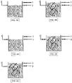
- the biofilm reactor has an inlet pipe (1), an outlet pipe with a valve (2) for biologically purified water, and an outlet pipe with a valve (3) for removal of sludge.
- A normal operation
- the required time for the loosening of particulate material can be from 1 minute to about 1 ⁇ 2 hour, dependent on the shape of the reactor and the strength of the turbulence. Thereafter, sufficient incoming water must pass through the reactor to get the sludge transported out of the reactor through pipe (3).
- the necessary amount of water to transport the sludge out of the reactor, and thus the volume of sludge water, will normally be from 1 to 3 times the reactor volume, dependent on how low the content of suspended material must be as one again returns to normal operation by opening the valve on pipe (2) ( Fig. 1 A) ..
- the biofilm reactor has an inlet pipe with a valve (1), an outlet pipe with a valve (2) for biologically purified water and an outlet pipe with a valve (3) for removal of sludge.
- A normal operation
- the reactors must have an outlet arrangement that prevents that the biofilm elements can leave the reactor, at the same time as purified water and sludge can be led out through pipe (2) and pipe (3), respectively.
- the reactor may comprise a mixing mechanism for transport of the water and substrate and which supplies oxygen to an aerobic process at the same time.
- mixing mechanisms will be diffuser aerators and ejector aerators.
- the reactor may comprise a mixing mechanism for transport of the water and the substrate in an anaerobic and in an anoxic process.
- mixing mechanisms will be mechanical stirrers, circular pumping and anaerobic gas agitation.
- the present invention has many advantages. There is no need for pumping of recycled sludge. There is no risk of discharge of sludge.
- the concentration of suspended material out of the bioreactor is low. Thus, the particle load on the sludge separation step will be low and one can use many alternative sludge separation processes, such as, for example, sedimentation, flotation, fine sieving or filtration.
- the bioreactor can handle considerably higher loads than an activated sludge process, so that the necessary bioreactor volume is considerably smaller and one gets a compact purification plant.
- the biofilm elements in the present invention will break up large gas bubbles, reduce the velocity of all the gas bubbles and increase the distance the gas bubbles must travel to get to the surface of the liquid in the reactor. Thereby, one achieves a considerably better oxygen transfer and a lower energy consumption than in an activated sludge process.
- the present invention also has many advantages with regard to other biofilm processes.
- Submerged biological filters with a stationary biofilm medium and without back-flushing have problems with blocking and channel formation, in addition to that there is no access to the diffusion aerators at the bottom of the reactors.
- the biofilm elements can simply be shovelled, sucked or pumped out of the reactors.
- the present invention has a higher specific biofilm surface area and a considerably higher capacity than the submerged biological filters mentioned above, so that the bioreactor becomes more compact.
- the present invention Compared to BAF processes, the present invention has the advantage that one does not have to have basins to store water that shall be used for the back-flushing. One can also have a continuous supply of water to the present invention. Furthermore, the present invention tolerates waste waters with a higher concentration of suspended material than what the BAF processes tolerate. With the present invention one has more freedom in the choice of bioreactor shapes and forms. BAF processes have a high pressure drop, while the present invention has a negligible pressure drop across the bioreactor.
- the present invention has a greater extent of filling of biofilm elements. This results in an increased biofilm surface area.
- the biofilm elements move around freely and follow the flow pattern of the water in the reactor. This means that the velocity gradient between the biofilm elements and the water is relatively small.
- the biofilm elements have hindered or no movement and the velocity gradient between the biofilm elements and the water becomes greater. This results in a better transfer of substrate and oxygen to the biofilm so that the rates of reaction increase. Together with an increased biofilm surface area, this means that the present invention leads to a very compact process. The oxygen transfer is also better than in a "moving bed” process.
- the gas bubbles are, to some extent, slowed down by the biofilm elements, but because the biofilm elements are largely following the water stream that is created by the air bubbles, the effect is considerably smaller than in the present invention where the biofilm elements have a limited or no movement.
- the present invention will thereby have up to 50 % higher specific oxygen transfer than a "moving bed” process.
- a high sludge production was previously regarded as a disadvantage, now it is viewed as an advantage.
- a higher biological sludge production means a lower energy consumption, in that the oxygen requirement and thus the need for air is lower.
- the need for oxygen will be typically reduced by 10 to 20 %. If one has degradation tanks on the purification plant, more biological sludge will mean more energy recovery in the form of biogas.
- the present invention is considerably simpler to construct and operate.
- the energy costs are considerably lower than for a fluidized bed process, because of the high pump costs to keep the biofilm medium (normally sand) fluidized.
- the design of the reactors (4) represents no limitation for the invention, but it will typically have a flat bottom and vertical walls.
- the effective depth of the reactor (4) will typically be in the area 1.5 to 12 meters, normally 3.0 to 8.0 meters.
- the choice of material for the manufacture of the reactor (4) is of no importance for the process and can be chosen freely.
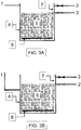
- the inflow of water to the reactor (4) can comprise one or more inlet zones, typically arranged with pipes (1) or channel constructions.
- the water can either enter at the top of the reactor so that one has a water level gap (see figure 3 A) or one can have a submerged inlet (see figure 3B ).
- the inlet must therefore be submersed or at the same level as the surface of the water in the reactor during normal operation.
- the direction of flow of water through the reactor (4) can be both horizontal and vertical.
- the outlet of water from the reactor can comprise one or more outlet zones (7), typically with an arrangement to keep the biofilm elements (5) in place in the reactor.
- the outlet arrangement will typically be characterised in that a construction with openings is used that are smaller than the linear dimensions of the biofilm elements (5).
- the aeration system in an aerobic reactor shall ensure that oxygen is supplied to the bioprocess and sufficient energy is provided to tear off loose excess sludge and keep the sludge in suspension in connection with the washing process.
- the aeration system will typically be placed at the bottom of the reactor (4) and be arranged so that the air is distributed in the largest part of the horizontal extent of the reactor (4).
Landscapes
- Life Sciences & Earth Sciences (AREA)
- Chemical & Material Sciences (AREA)
- Organic Chemistry (AREA)
- Water Supply & Treatment (AREA)
- Engineering & Computer Science (AREA)
- Environmental & Geological Engineering (AREA)
- Hydrology & Water Resources (AREA)
- Biodiversity & Conservation Biology (AREA)
- Microbiology (AREA)
- Chemical Kinetics & Catalysis (AREA)
- Health & Medical Sciences (AREA)
- Molecular Biology (AREA)
- Biological Treatment Of Waste Water (AREA)
- Purification Treatments By Anaerobic Or Anaerobic And Aerobic Bacteria Or Animals (AREA)
Priority Applications (1)
| Application Number | Priority Date | Filing Date | Title |
|---|---|---|---|
| PL10783628T PL2438019T3 (pl) | 2009-06-03 | 2010-06-03 | Sposób biologicznego oczyszczania ścieków |
Applications Claiming Priority (2)
| Application Number | Priority Date | Filing Date | Title |
|---|---|---|---|
| NO20092151A NO329665B1 (no) | 2009-06-03 | 2009-06-03 | Fremgangsmate og reaktor for behandling av vann |
| PCT/NO2010/000207 WO2010140898A1 (en) | 2009-06-03 | 2010-06-03 | Method and reactor for biological purification of waste water. |
Publications (3)
| Publication Number | Publication Date |
|---|---|
| EP2438019A1 EP2438019A1 (en) | 2012-04-11 |
| EP2438019A4 EP2438019A4 (en) | 2015-06-03 |
| EP2438019B1 true EP2438019B1 (en) | 2019-03-27 |
Family
ID=43297895
Family Applications (1)
| Application Number | Title | Priority Date | Filing Date |
|---|---|---|---|
| EP10783628.0A Active EP2438019B1 (en) | 2009-06-03 | 2010-06-03 | Method for biological purification of waste water. |
Country Status (19)
| Country | Link |
|---|---|
| US (1) | US9758402B2 (da) |
| EP (1) | EP2438019B1 (da) |
| JP (2) | JP2012528716A (da) |
| KR (3) | KR20170001744A (da) |
| CN (1) | CN102448894B (da) |
| AU (1) | AU2010254693B2 (da) |
| BR (1) | BRPI1010782B1 (da) |
| CA (1) | CA2763258C (da) |
| DK (1) | DK2438019T3 (da) |
| EA (1) | EA022513B1 (da) |
| ES (1) | ES2732148T3 (da) |
| IL (1) | IL216591A (da) |
| MX (1) | MX2011012273A (da) |
| NO (1) | NO329665B1 (da) |
| NZ (1) | NZ596609A (da) |
| PL (1) | PL2438019T3 (da) |
| PT (1) | PT2438019T (da) |
| TR (1) | TR201907175T4 (da) |
| WO (1) | WO2010140898A1 (da) |
Families Citing this family (19)
| Publication number | Priority date | Publication date | Assignee | Title |
|---|---|---|---|---|
| NO329665B1 (no) | 2009-06-03 | 2010-11-29 | Biowater Technology AS | Fremgangsmate og reaktor for behandling av vann |
| WO2012087151A1 (en) * | 2010-12-22 | 2012-06-28 | Biowater Technology AS | Carrier element for purification of water |
| EP2508488B1 (en) * | 2011-04-04 | 2015-06-10 | Veolia Water Solutions & Technologies Support | Improved biological waste water purification reactor and method |
| US9162910B2 (en) | 2011-07-11 | 2015-10-20 | Allegheny-Singer Research Institute | Fluid treatment system |
| CN102351304A (zh) * | 2011-09-09 | 2012-02-15 | 北京林业大学 | 一种解决反冲洗问题的新型曝气生物滤池 |
| NO20131634A1 (no) * | 2013-12-09 | 2015-06-10 | Biowater Technology AS | Fremgangsmåte for biologisk rensing av vann |
| NO336908B1 (no) | 2014-05-28 | 2015-11-23 | Hias Iks | Metode for biologisk vannrensing av avløpsvann i en kontinuerlig prosess, samt reaktor for kontinuerlig biologisk vannrensing av avløpsvann. |
| US10392277B2 (en) * | 2015-03-11 | 2019-08-27 | Bl Technologies, Inc. | Backwash method for biological reactors |
| NO342658B1 (en) * | 2015-10-06 | 2018-06-25 | Biowater Tech As | Method and reactor to alternate between stationary bed and moving bed for treatment of water, without changing the water level in the reactor |
| DK3552679T3 (da) * | 2016-12-06 | 2023-09-18 | Passavant Geiger Gmbh | Sandfilterbassin med horisontalgennemstrømning og vandbehandlingsfremgangsmåde deraf |
| CN106893701B (zh) * | 2017-03-13 | 2019-11-26 | 中国水产科学研究院黑龙江水产研究所 | 高碱型盐碱水生物处理挂膜的方法 |
| JP6912987B2 (ja) * | 2017-09-26 | 2021-08-04 | メタウォーター株式会社 | 散水ろ床の洗浄方法および散水ろ床 |
| CN107915316B (zh) * | 2017-10-20 | 2023-06-30 | 浙江大学 | 颗粒污泥和生物填料协同强化的厌氧氨氧化深度脱氮反应器及方法 |
| US10913667B2 (en) * | 2017-12-08 | 2021-02-09 | Westech Engineering, Inc. | Multi-media clarification systems and methods |
| JP6597815B2 (ja) * | 2018-02-20 | 2019-10-30 | 栗田工業株式会社 | 好気性生物処理装置の運転方法 |
| CN110980948B (zh) * | 2019-12-14 | 2022-02-18 | 浙江永续环境工程有限公司 | 兼氧型流动生物床反应器 |
| CN113104968B (zh) * | 2021-03-23 | 2022-09-16 | 上海师范大学 | 一种用于筛板塔式生物反应器的生物膜载体及生物反应器 |
| CN114031174B (zh) * | 2021-11-22 | 2022-10-28 | 广州市水之道生态环境修复有限公司 | 一种太阳能环流曝气悬浮型生物滤池 |
| DE102021133020A1 (de) | 2021-12-14 | 2023-06-15 | dsf Danz Special Foams GmbH | Bewuchskörper für Mikroorganismen in biologischen Kläranlagen und Verfahren zu dessen Herstellung |
Family Cites Families (25)
| Publication number | Priority date | Publication date | Assignee | Title |
|---|---|---|---|---|
| JPS5068991A (da) * | 1973-10-24 | 1975-06-09 | ||
| US4253947A (en) | 1979-02-12 | 1981-03-03 | Kansas State University Research Foundation | Method for wastewater treatment in fluidized bed biological reactors |
| US4322296A (en) * | 1980-08-12 | 1982-03-30 | Kansas State Univ. Research Foundation | Method for wastewater treatment in fluidized bed biological reactors |
| JP2552493B2 (ja) * | 1987-07-23 | 1996-11-13 | 千代田化工建設株式会社 | 加圧式上向流排水処理装置およびその使用法 |
| US5057221A (en) * | 1988-12-19 | 1991-10-15 | Weyerhaeuser Company | Aerobic biological dehalogenation reactor |
| JPH0729096B2 (ja) * | 1989-06-12 | 1995-04-05 | 荏原インフイルコ株式会社 | 水処理方法 |
| DE69104629D1 (de) * | 1990-01-23 | 1994-11-17 | Kaldnes Miljoteknologi As | Methode und reaktor zur reinigung von wasser. |
| JPH0568991A (ja) | 1991-09-10 | 1993-03-23 | Chiyoda Corp | 微生物担持体充填網袋 |
| US5126042A (en) | 1991-10-31 | 1992-06-30 | Malone Ronald F | Floating media biofilter |
| JPH0677650B2 (ja) * | 1991-11-15 | 1994-10-05 | 荏原インフィルコ株式会社 | 上向流ろ過方法及び装置 |
| US5350505A (en) * | 1993-03-01 | 1994-09-27 | Jet, Inc. | Plastic media filter |
| SE517400C2 (sv) * | 1994-03-16 | 2002-06-04 | Kaldnes Miljoeteknologi As | Biofilmsbärare för vatten- och avloppsvattenrening |
| CA2263668A1 (en) * | 1996-08-19 | 1998-02-26 | Wolfgang Schenk Gmbh | Bioreactor |
| US6007712A (en) * | 1997-02-28 | 1999-12-28 | Kuraray Co., Ltd. | Waste water treatment apparatus |
| WO2000034187A1 (en) * | 1998-12-04 | 2000-06-15 | Knud Peter Brockdorff | A method and a bio reactor for use in the purification of water, and a bio-element for use in this connection |
| JP2000185293A (ja) * | 1998-12-22 | 2000-07-04 | Sumitomo Heavy Ind Ltd | 生物ろ過装置 |
| JP2000202482A (ja) * | 1999-01-14 | 2000-07-25 | Denso Corp | 排水の浄化方法及び浄化装置 |
| CN100337936C (zh) * | 2004-08-08 | 2007-09-19 | 江苏鹏鹞环境工程技术研究中心有限公司 | 改良的生物反应器 |
| FR2885126B1 (fr) | 2005-04-27 | 2007-08-10 | Agronomique Inst Nat Rech | Procede d'epuration d'effluent en reacteur anaerobie, et utilisation d'un reacteur biologique pour le traitement d'effluent |
| FI117763B (fi) * | 2005-12-30 | 2007-02-15 | Suunnittelutoimisto Bestdan Oy | Kansirakenne |
| PL1971555T3 (pl) * | 2006-01-04 | 2013-08-30 | Clewer Oy | Bioreaktor i sposób biologicznego oczyszczania wody |
| CA2550121A1 (en) * | 2006-06-07 | 2007-12-07 | Flynn Water Technologies Inc. | Biomass carrier promoting simultaneous nitrification-de-nitrification |
| US7914678B2 (en) * | 2008-05-30 | 2011-03-29 | Beggs Robert A | Backwashing unsaturated wastewater filter |
| NO329665B1 (no) | 2009-06-03 | 2010-11-29 | Biowater Technology AS | Fremgangsmate og reaktor for behandling av vann |
| JP5137906B2 (ja) | 2009-06-19 | 2013-02-06 | 日本電信電話株式会社 | 光アクセス網、光加入者装置および光アクセス網の通信設定方法 |
-
2009
- 2009-06-03 NO NO20092151A patent/NO329665B1/no unknown
-
2010
- 2010-06-03 US US13/375,103 patent/US9758402B2/en active Active
- 2010-06-03 KR KR1020167036367A patent/KR20170001744A/ko not_active Ceased
- 2010-06-03 EA EA201190324A patent/EA022513B1/ru not_active IP Right Cessation
- 2010-06-03 EP EP10783628.0A patent/EP2438019B1/en active Active
- 2010-06-03 ES ES10783628T patent/ES2732148T3/es active Active
- 2010-06-03 MX MX2011012273A patent/MX2011012273A/es active IP Right Grant
- 2010-06-03 CA CA2763258A patent/CA2763258C/en active Active
- 2010-06-03 TR TR2019/07175T patent/TR201907175T4/tr unknown
- 2010-06-03 CN CN201080023640.4A patent/CN102448894B/zh active Active
- 2010-06-03 KR KR20117029196A patent/KR20120039530A/ko not_active Ceased
- 2010-06-03 AU AU2010254693A patent/AU2010254693B2/en active Active
- 2010-06-03 WO PCT/NO2010/000207 patent/WO2010140898A1/en not_active Ceased
- 2010-06-03 KR KR1020177037158A patent/KR20180000752A/ko not_active Ceased
- 2010-06-03 NZ NZ596609A patent/NZ596609A/xx not_active IP Right Cessation
- 2010-06-03 JP JP2012513895A patent/JP2012528716A/ja active Pending
- 2010-06-03 PT PT10783628T patent/PT2438019T/pt unknown
- 2010-06-03 BR BRPI1010782-7A patent/BRPI1010782B1/pt active IP Right Grant
- 2010-06-03 PL PL10783628T patent/PL2438019T3/pl unknown
- 2010-06-03 DK DK10783628.0T patent/DK2438019T3/da active
-
2011
- 2011-11-24 IL IL216591A patent/IL216591A/en active IP Right Grant
-
2015
- 2015-02-20 JP JP2015031977A patent/JP5945342B2/ja active Active
Non-Patent Citations (1)
| Title |
|---|
| None * |
Also Published As
| Publication number | Publication date |
|---|---|
| MX2011012273A (es) | 2012-01-30 |
| NZ596609A (en) | 2013-05-31 |
| IL216591A0 (en) | 2012-02-29 |
| EA022513B1 (ru) | 2016-01-29 |
| US20120067818A1 (en) | 2012-03-22 |
| NO20092151A (no) | 2010-11-29 |
| JP2015145006A (ja) | 2015-08-13 |
| KR20170001744A (ko) | 2017-01-04 |
| EP2438019A1 (en) | 2012-04-11 |
| EA201190324A1 (ru) | 2012-06-29 |
| BRPI1010782B1 (pt) | 2020-03-10 |
| CN102448894A (zh) | 2012-05-09 |
| KR20120039530A (ko) | 2012-04-25 |
| JP5945342B2 (ja) | 2016-07-05 |
| CA2763258C (en) | 2021-08-03 |
| DK2438019T3 (da) | 2019-06-17 |
| KR20180000752A (ko) | 2018-01-03 |
| AU2010254693B2 (en) | 2014-06-19 |
| TR201907175T4 (tr) | 2019-06-21 |
| HK1165399A1 (en) | 2012-10-05 |
| EP2438019A4 (en) | 2015-06-03 |
| PT2438019T (pt) | 2019-05-31 |
| PL2438019T3 (pl) | 2019-12-31 |
| BRPI1010782A2 (pt) | 2016-03-22 |
| CN102448894B (zh) | 2014-04-09 |
| NO329665B1 (no) | 2010-11-29 |
| IL216591A (en) | 2015-05-31 |
| US9758402B2 (en) | 2017-09-12 |
| ES2732148T3 (es) | 2019-11-20 |
| JP2012528716A (ja) | 2012-11-15 |
| CA2763258A1 (en) | 2010-12-09 |
| AU2010254693A1 (en) | 2011-12-08 |
| WO2010140898A1 (en) | 2010-12-09 |
Similar Documents
| Publication | Publication Date | Title |
|---|---|---|
| EP2438019B1 (en) | Method for biological purification of waste water. | |
| EP2254842B1 (en) | Method and device for the treatment of waste water | |
| US20160304369A1 (en) | Method for biological purification of water | |
| JP3183406B2 (ja) | 水の浄化用の方法とリアクター | |
| CN105585119A (zh) | 一种硝化反硝化两相膨胀床反应器及污水处理工艺 | |
| WO2016061664A1 (en) | Water treatment system and method | |
| WO2017061872A1 (en) | Method and reactor to alternate between stationary bed and moving bed for treatment of water, without changing the water level in the reactor | |
| CN217479275U (zh) | 一种分布式污水处理装置 | |
| CN213171940U (zh) | 模块化集成式高效污水处理系统 | |
| KR100873052B1 (ko) | 개방형 오폐수 및 하수 처리장치 | |
| KR101147247B1 (ko) | 회전원통형 질산화반응기를 포함하는 고효율 질산화반응조 및 이를 이용한 수처리 시스템 | |
| KR100862184B1 (ko) | 비중이 조절된 담체를 사용한 혐기/무산소 반응조, 이를 이용한 폐수처리장치 및 폐수처리방법 | |
| HK1165399B (en) | Method and reactor for biological purification of waste water | |
| JPS5857238B2 (ja) | 廃水の処理方法 | |
| JP2003033795A (ja) | 生物脱窒装置及び生物脱窒方法 | |
| JPH04197493A (ja) | 汚水の濾過方法および装置 | |
| CN112573649A (zh) | 硝酸根废水处理装置及方法 | |
| WO2012087151A1 (en) | Carrier element for purification of water |
Legal Events
| Date | Code | Title | Description |
|---|---|---|---|
| PUAI | Public reference made under article 153(3) epc to a published international application that has entered the european phase |
Free format text: ORIGINAL CODE: 0009012 |
|
| 17P | Request for examination filed |
Effective date: 20111114 |
|
| AK | Designated contracting states |
Kind code of ref document: A1 Designated state(s): AL AT BE BG CH CY CZ DE DK EE ES FI FR GB GR HR HU IE IS IT LI LT LU LV MC MK MT NL NO PL PT RO SE SI SK SM TR |
|
| DAX | Request for extension of the european patent (deleted) | ||
| RA4 | Supplementary search report drawn up and despatched (corrected) |
Effective date: 20150508 |
|
| RIC1 | Information provided on ipc code assigned before grant |
Ipc: C02F 3/10 20060101ALI20150430BHEP Ipc: C02F 3/06 20060101ALI20150430BHEP Ipc: C02F 3/12 20060101AFI20150430BHEP Ipc: C02F 3/08 20060101ALI20150430BHEP |
|
| STAA | Information on the status of an ep patent application or granted ep patent |
Free format text: STATUS: EXAMINATION IS IN PROGRESS |
|
| 17Q | First examination report despatched |
Effective date: 20180215 |
|
| GRAP | Despatch of communication of intention to grant a patent |
Free format text: ORIGINAL CODE: EPIDOSNIGR1 |
|
| STAA | Information on the status of an ep patent application or granted ep patent |
Free format text: STATUS: GRANT OF PATENT IS INTENDED |
|
| INTG | Intention to grant announced |
Effective date: 20181123 |
|
| GRAS | Grant fee paid |
Free format text: ORIGINAL CODE: EPIDOSNIGR3 |
|
| GRAA | (expected) grant |
Free format text: ORIGINAL CODE: 0009210 |
|
| STAA | Information on the status of an ep patent application or granted ep patent |
Free format text: STATUS: THE PATENT HAS BEEN GRANTED |
|
| AK | Designated contracting states |
Kind code of ref document: B1 Designated state(s): AL AT BE BG CH CY CZ DE DK EE ES FI FR GB GR HR HU IE IS IT LI LT LU LV MC MK MT NL NO PL PT RO SE SI SK SM TR |
|
| REG | Reference to a national code |
Ref country code: GB Ref legal event code: FG4D |
|
| REG | Reference to a national code |
Ref country code: CH Ref legal event code: EP |
|
| REG | Reference to a national code |
Ref country code: AT Ref legal event code: REF Ref document number: 1112841 Country of ref document: AT Kind code of ref document: T Effective date: 20190415 |
|
| REG | Reference to a national code |
Ref country code: IE Ref legal event code: FG4D |
|
| REG | Reference to a national code |
Ref country code: DE Ref legal event code: R096 Ref document number: 602010057860 Country of ref document: DE |
|
| REG | Reference to a national code |
Ref country code: PT Ref legal event code: SC4A Ref document number: 2438019 Country of ref document: PT Date of ref document: 20190531 Kind code of ref document: T Free format text: AVAILABILITY OF NATIONAL TRANSLATION Effective date: 20190513 |
|
| REG | Reference to a national code |
Ref country code: DK Ref legal event code: T3 Effective date: 20190613 |
|
| REG | Reference to a national code |
Ref country code: SE Ref legal event code: TRGR |
|
| REG | Reference to a national code |
Ref country code: NL Ref legal event code: FP |
|
| PG25 | Lapsed in a contracting state [announced via postgrant information from national office to epo] |
Ref country code: LT Free format text: LAPSE BECAUSE OF FAILURE TO SUBMIT A TRANSLATION OF THE DESCRIPTION OR TO PAY THE FEE WITHIN THE PRESCRIBED TIME-LIMIT Effective date: 20190327 Ref country code: NO Free format text: LAPSE BECAUSE OF FAILURE TO SUBMIT A TRANSLATION OF THE DESCRIPTION OR TO PAY THE FEE WITHIN THE PRESCRIBED TIME-LIMIT Effective date: 20190627 |
|
| PG25 | Lapsed in a contracting state [announced via postgrant information from national office to epo] |
Ref country code: BG Free format text: LAPSE BECAUSE OF FAILURE TO SUBMIT A TRANSLATION OF THE DESCRIPTION OR TO PAY THE FEE WITHIN THE PRESCRIBED TIME-LIMIT Effective date: 20190627 Ref country code: LV Free format text: LAPSE BECAUSE OF FAILURE TO SUBMIT A TRANSLATION OF THE DESCRIPTION OR TO PAY THE FEE WITHIN THE PRESCRIBED TIME-LIMIT Effective date: 20190327 Ref country code: HR Free format text: LAPSE BECAUSE OF FAILURE TO SUBMIT A TRANSLATION OF THE DESCRIPTION OR TO PAY THE FEE WITHIN THE PRESCRIBED TIME-LIMIT Effective date: 20190327 |
|
| REG | Reference to a national code |
Ref country code: SK Ref legal event code: T3 Ref document number: E 31200 Country of ref document: SK |
|
| REG | Reference to a national code |
Ref country code: AT Ref legal event code: MK05 Ref document number: 1112841 Country of ref document: AT Kind code of ref document: T Effective date: 20190327 |
|
| REG | Reference to a national code |
Ref country code: GR Ref legal event code: EP Ref document number: 20190401756 Country of ref document: GR Effective date: 20190906 |
|
| PG25 | Lapsed in a contracting state [announced via postgrant information from national office to epo] |
Ref country code: AL Free format text: LAPSE BECAUSE OF FAILURE TO SUBMIT A TRANSLATION OF THE DESCRIPTION OR TO PAY THE FEE WITHIN THE PRESCRIBED TIME-LIMIT Effective date: 20190327 Ref country code: RO Free format text: LAPSE BECAUSE OF FAILURE TO SUBMIT A TRANSLATION OF THE DESCRIPTION OR TO PAY THE FEE WITHIN THE PRESCRIBED TIME-LIMIT Effective date: 20190327 Ref country code: CZ Free format text: LAPSE BECAUSE OF FAILURE TO SUBMIT A TRANSLATION OF THE DESCRIPTION OR TO PAY THE FEE WITHIN THE PRESCRIBED TIME-LIMIT Effective date: 20190327 Ref country code: EE Free format text: LAPSE BECAUSE OF FAILURE TO SUBMIT A TRANSLATION OF THE DESCRIPTION OR TO PAY THE FEE WITHIN THE PRESCRIBED TIME-LIMIT Effective date: 20190327 |
|
| REG | Reference to a national code |
Ref country code: ES Ref legal event code: FG2A Ref document number: 2732148 Country of ref document: ES Kind code of ref document: T3 Effective date: 20191120 |
|
| PG25 | Lapsed in a contracting state [announced via postgrant information from national office to epo] |
Ref country code: SM Free format text: LAPSE BECAUSE OF FAILURE TO SUBMIT A TRANSLATION OF THE DESCRIPTION OR TO PAY THE FEE WITHIN THE PRESCRIBED TIME-LIMIT Effective date: 20190327 |
|
| PG25 | Lapsed in a contracting state [announced via postgrant information from national office to epo] |
Ref country code: IS Free format text: LAPSE BECAUSE OF FAILURE TO SUBMIT A TRANSLATION OF THE DESCRIPTION OR TO PAY THE FEE WITHIN THE PRESCRIBED TIME-LIMIT Effective date: 20190727 Ref country code: AT Free format text: LAPSE BECAUSE OF FAILURE TO SUBMIT A TRANSLATION OF THE DESCRIPTION OR TO PAY THE FEE WITHIN THE PRESCRIBED TIME-LIMIT Effective date: 20190327 |
|
| REG | Reference to a national code |
Ref country code: DE Ref legal event code: R097 Ref document number: 602010057860 Country of ref document: DE |
|
| PG25 | Lapsed in a contracting state [announced via postgrant information from national office to epo] |
Ref country code: MC Free format text: LAPSE BECAUSE OF FAILURE TO SUBMIT A TRANSLATION OF THE DESCRIPTION OR TO PAY THE FEE WITHIN THE PRESCRIBED TIME-LIMIT Effective date: 20190327 |
|
| PLBE | No opposition filed within time limit |
Free format text: ORIGINAL CODE: 0009261 |
|
| STAA | Information on the status of an ep patent application or granted ep patent |
Free format text: STATUS: NO OPPOSITION FILED WITHIN TIME LIMIT |
|
| PG25 | Lapsed in a contracting state [announced via postgrant information from national office to epo] |
Ref country code: SI Free format text: LAPSE BECAUSE OF FAILURE TO SUBMIT A TRANSLATION OF THE DESCRIPTION OR TO PAY THE FEE WITHIN THE PRESCRIBED TIME-LIMIT Effective date: 20190327 |
|
| 26N | No opposition filed |
Effective date: 20200103 |
|
| REG | Reference to a national code |
Ref country code: BE Ref legal event code: MM Effective date: 20190630 |
|
| PG25 | Lapsed in a contracting state [announced via postgrant information from national office to epo] |
Ref country code: BE Free format text: LAPSE BECAUSE OF NON-PAYMENT OF DUE FEES Effective date: 20190630 Ref country code: LU Free format text: LAPSE BECAUSE OF NON-PAYMENT OF DUE FEES Effective date: 20190603 |
|
| PG25 | Lapsed in a contracting state [announced via postgrant information from national office to epo] |
Ref country code: CY Free format text: LAPSE BECAUSE OF FAILURE TO SUBMIT A TRANSLATION OF THE DESCRIPTION OR TO PAY THE FEE WITHIN THE PRESCRIBED TIME-LIMIT Effective date: 20190327 |
|
| PG25 | Lapsed in a contracting state [announced via postgrant information from national office to epo] |
Ref country code: MT Free format text: LAPSE BECAUSE OF FAILURE TO SUBMIT A TRANSLATION OF THE DESCRIPTION OR TO PAY THE FEE WITHIN THE PRESCRIBED TIME-LIMIT Effective date: 20190327 Ref country code: HU Free format text: LAPSE BECAUSE OF FAILURE TO SUBMIT A TRANSLATION OF THE DESCRIPTION OR TO PAY THE FEE WITHIN THE PRESCRIBED TIME-LIMIT; INVALID AB INITIO Effective date: 20100603 |
|
| PG25 | Lapsed in a contracting state [announced via postgrant information from national office to epo] |
Ref country code: MK Free format text: LAPSE BECAUSE OF FAILURE TO SUBMIT A TRANSLATION OF THE DESCRIPTION OR TO PAY THE FEE WITHIN THE PRESCRIBED TIME-LIMIT Effective date: 20190327 |
|
| PGFP | Annual fee paid to national office [announced via postgrant information from national office to epo] |
Ref country code: GR Payment date: 20220623 Year of fee payment: 13 |
|
| PGFP | Annual fee paid to national office [announced via postgrant information from national office to epo] |
Ref country code: TR Payment date: 20230518 Year of fee payment: 14 Ref country code: SK Payment date: 20230509 Year of fee payment: 14 |
|
| PG25 | Lapsed in a contracting state [announced via postgrant information from national office to epo] |
Ref country code: GR Free format text: LAPSE BECAUSE OF NON-PAYMENT OF DUE FEES Effective date: 20240109 |
|
| PG25 | Lapsed in a contracting state [announced via postgrant information from national office to epo] |
Ref country code: GR Free format text: LAPSE BECAUSE OF NON-PAYMENT OF DUE FEES Effective date: 20240109 |
|
| REG | Reference to a national code |
Ref country code: SK Ref legal event code: MM4A Ref document number: E 31200 Country of ref document: SK Effective date: 20240603 |
|
| PG25 | Lapsed in a contracting state [announced via postgrant information from national office to epo] |
Ref country code: SK Free format text: LAPSE BECAUSE OF NON-PAYMENT OF DUE FEES Effective date: 20240603 |
|
| PG25 | Lapsed in a contracting state [announced via postgrant information from national office to epo] |
Ref country code: SK Free format text: LAPSE BECAUSE OF NON-PAYMENT OF DUE FEES Effective date: 20240603 |
|
| PGFP | Annual fee paid to national office [announced via postgrant information from national office to epo] |
Ref country code: FI Payment date: 20250603 Year of fee payment: 16 |
|
| PGFP | Annual fee paid to national office [announced via postgrant information from national office to epo] |
Ref country code: PL Payment date: 20250601 Year of fee payment: 16 Ref country code: DE Payment date: 20250602 Year of fee payment: 16 |
|
| PGFP | Annual fee paid to national office [announced via postgrant information from national office to epo] |
Ref country code: GB Payment date: 20250613 Year of fee payment: 16 Ref country code: DK Payment date: 20250612 Year of fee payment: 16 |
|
| PGFP | Annual fee paid to national office [announced via postgrant information from national office to epo] |
Ref country code: NL Payment date: 20250602 Year of fee payment: 16 |
|
| PGFP | Annual fee paid to national office [announced via postgrant information from national office to epo] |
Ref country code: PT Payment date: 20250506 Year of fee payment: 16 |
|
| PGFP | Annual fee paid to national office [announced via postgrant information from national office to epo] |
Ref country code: FR Payment date: 20250612 Year of fee payment: 16 |
|
| PGFP | Annual fee paid to national office [announced via postgrant information from national office to epo] |
Ref country code: IE Payment date: 20250602 Year of fee payment: 16 |
|
| PGFP | Annual fee paid to national office [announced via postgrant information from national office to epo] |
Ref country code: SE Payment date: 20250604 Year of fee payment: 16 |
|
| PGFP | Annual fee paid to national office [announced via postgrant information from national office to epo] |
Ref country code: ES Payment date: 20250903 Year of fee payment: 16 |
|
| PGFP | Annual fee paid to national office [announced via postgrant information from national office to epo] |
Ref country code: IT Payment date: 20250602 Year of fee payment: 16 |
|
| PGFP | Annual fee paid to national office [announced via postgrant information from national office to epo] |
Ref country code: CH Payment date: 20250701 Year of fee payment: 16 |