EP2437795B1 - Dekontaminierung geschlossener räume mithilfe von gasförmigem chlorindioxid - Google Patents
Dekontaminierung geschlossener räume mithilfe von gasförmigem chlorindioxid Download PDFInfo
- Publication number
- EP2437795B1 EP2437795B1 EP10783758.5A EP10783758A EP2437795B1 EP 2437795 B1 EP2437795 B1 EP 2437795B1 EP 10783758 A EP10783758 A EP 10783758A EP 2437795 B1 EP2437795 B1 EP 2437795B1
- Authority
- EP
- European Patent Office
- Prior art keywords
- chlorine dioxide
- emitter
- gas
- air
- concentration
- Prior art date
- Legal status (The legal status is an assumption and is not a legal conclusion. Google has not performed a legal analysis and makes no representation as to the accuracy of the status listed.)
- Not-in-force
Links
Images


Classifications
-
- A—HUMAN NECESSITIES
- A61—MEDICAL OR VETERINARY SCIENCE; HYGIENE
- A61L—METHODS OR APPARATUS FOR STERILISING MATERIALS OR OBJECTS IN GENERAL; DISINFECTION, STERILISATION OR DEODORISATION OF AIR; CHEMICAL ASPECTS OF BANDAGES, DRESSINGS, ABSORBENT PADS OR SURGICAL ARTICLES; MATERIALS FOR BANDAGES, DRESSINGS, ABSORBENT PADS OR SURGICAL ARTICLES
- A61L9/00—Disinfection, sterilisation or deodorisation of air
- A61L9/015—Disinfection, sterilisation or deodorisation of air using gaseous or vaporous substances, e.g. ozone
- A61L9/04—Disinfection, sterilisation or deodorisation of air using gaseous or vaporous substances, e.g. ozone using substances evaporated in the air without heating
- A61L9/12—Apparatus, e.g. holders, therefor
- A61L9/122—Apparatus, e.g. holders, therefor comprising a fan
-
- A—HUMAN NECESSITIES
- A61—MEDICAL OR VETERINARY SCIENCE; HYGIENE
- A61L—METHODS OR APPARATUS FOR STERILISING MATERIALS OR OBJECTS IN GENERAL; DISINFECTION, STERILISATION OR DEODORISATION OF AIR; CHEMICAL ASPECTS OF BANDAGES, DRESSINGS, ABSORBENT PADS OR SURGICAL ARTICLES; MATERIALS FOR BANDAGES, DRESSINGS, ABSORBENT PADS OR SURGICAL ARTICLES
- A61L2/00—Disinfection or sterilisation of materials or objects, in general; Accessories therefor
- A61L2/16—Disinfection or sterilisation of materials or objects, in general; Accessories therefor using chemical substances
- A61L2/20—Gaseous substances, e.g. vapours
-
- A—HUMAN NECESSITIES
- A61—MEDICAL OR VETERINARY SCIENCE; HYGIENE
- A61L—METHODS OR APPARATUS FOR STERILISING MATERIALS OR OBJECTS IN GENERAL; DISINFECTION, STERILISATION OR DEODORISATION OF AIR; CHEMICAL ASPECTS OF BANDAGES, DRESSINGS, ABSORBENT PADS OR SURGICAL ARTICLES; MATERIALS FOR BANDAGES, DRESSINGS, ABSORBENT PADS OR SURGICAL ARTICLES
- A61L9/00—Disinfection, sterilisation or deodorisation of air
- A61L9/015—Disinfection, sterilisation or deodorisation of air using gaseous or vaporous substances, e.g. ozone
-
- A—HUMAN NECESSITIES
- A61—MEDICAL OR VETERINARY SCIENCE; HYGIENE
- A61L—METHODS OR APPARATUS FOR STERILISING MATERIALS OR OBJECTS IN GENERAL; DISINFECTION, STERILISATION OR DEODORISATION OF AIR; CHEMICAL ASPECTS OF BANDAGES, DRESSINGS, ABSORBENT PADS OR SURGICAL ARTICLES; MATERIALS FOR BANDAGES, DRESSINGS, ABSORBENT PADS OR SURGICAL ARTICLES
- A61L9/00—Disinfection, sterilisation or deodorisation of air
- A61L9/14—Disinfection, sterilisation or deodorisation of air using sprayed or atomised substances including air-liquid contact processes
- A61L9/145—Disinfection, sterilisation or deodorisation of air using sprayed or atomised substances including air-liquid contact processes air-liquid contact processes, e.g. scrubbing
-
- C—CHEMISTRY; METALLURGY
- C01—INORGANIC CHEMISTRY
- C01B—NON-METALLIC ELEMENTS; COMPOUNDS THEREOF; METALLOIDS OR COMPOUNDS THEREOF NOT COVERED BY SUBCLASS C01C
- C01B11/00—Oxides or oxyacids of halogens; Salts thereof
- C01B11/02—Oxides of chlorine
- C01B11/022—Chlorine dioxide (ClO2)
-
- A—HUMAN NECESSITIES
- A61—MEDICAL OR VETERINARY SCIENCE; HYGIENE
- A61L—METHODS OR APPARATUS FOR STERILISING MATERIALS OR OBJECTS IN GENERAL; DISINFECTION, STERILISATION OR DEODORISATION OF AIR; CHEMICAL ASPECTS OF BANDAGES, DRESSINGS, ABSORBENT PADS OR SURGICAL ARTICLES; MATERIALS FOR BANDAGES, DRESSINGS, ABSORBENT PADS OR SURGICAL ARTICLES
- A61L2/00—Disinfection or sterilisation of materials or objects, in general; Accessories therefor
- A61L2/16—Disinfection or sterilisation of materials or objects, in general; Accessories therefor using chemical substances
- A61L2/22—Phase substances, e.g. smokes or aerosols
-
- A—HUMAN NECESSITIES
- A61—MEDICAL OR VETERINARY SCIENCE; HYGIENE
- A61L—METHODS OR APPARATUS FOR STERILISING MATERIALS OR OBJECTS IN GENERAL; DISINFECTION, STERILISATION OR DEODORISATION OF AIR; CHEMICAL ASPECTS OF BANDAGES, DRESSINGS, ABSORBENT PADS OR SURGICAL ARTICLES; MATERIALS FOR BANDAGES, DRESSINGS, ABSORBENT PADS OR SURGICAL ARTICLES
- A61L2103/00—Materials or objects being the target of disinfection or sterilisation
- A61L2103/75—Room floors or walls
-
- A—HUMAN NECESSITIES
- A61—MEDICAL OR VETERINARY SCIENCE; HYGIENE
- A61L—METHODS OR APPARATUS FOR STERILISING MATERIALS OR OBJECTS IN GENERAL; DISINFECTION, STERILISATION OR DEODORISATION OF AIR; CHEMICAL ASPECTS OF BANDAGES, DRESSINGS, ABSORBENT PADS OR SURGICAL ARTICLES; MATERIALS FOR BANDAGES, DRESSINGS, ABSORBENT PADS OR SURGICAL ARTICLES
- A61L2209/00—Aspects relating to disinfection, sterilisation or deodorisation of air
- A61L2209/20—Method-related aspects
- A61L2209/22—Treatment by sorption, e.g. absorption, adsorption, chemisorption, scrubbing, wet cleaning
-
- A—HUMAN NECESSITIES
- A61—MEDICAL OR VETERINARY SCIENCE; HYGIENE
- A61L—METHODS OR APPARATUS FOR STERILISING MATERIALS OR OBJECTS IN GENERAL; DISINFECTION, STERILISATION OR DEODORISATION OF AIR; CHEMICAL ASPECTS OF BANDAGES, DRESSINGS, ABSORBENT PADS OR SURGICAL ARTICLES; MATERIALS FOR BANDAGES, DRESSINGS, ABSORBENT PADS OR SURGICAL ARTICLES
- A61L9/00—Disinfection, sterilisation or deodorisation of air
- A61L9/015—Disinfection, sterilisation or deodorisation of air using gaseous or vaporous substances, e.g. ozone
- A61L9/02—Disinfection, sterilisation or deodorisation of air using gaseous or vaporous substances, e.g. ozone using substances evaporated in the air by heating or combustion
- A61L9/03—Apparatus therefor
-
- A—HUMAN NECESSITIES
- A61—MEDICAL OR VETERINARY SCIENCE; HYGIENE
- A61L—METHODS OR APPARATUS FOR STERILISING MATERIALS OR OBJECTS IN GENERAL; DISINFECTION, STERILISATION OR DEODORISATION OF AIR; CHEMICAL ASPECTS OF BANDAGES, DRESSINGS, ABSORBENT PADS OR SURGICAL ARTICLES; MATERIALS FOR BANDAGES, DRESSINGS, ABSORBENT PADS OR SURGICAL ARTICLES
- A61L9/00—Disinfection, sterilisation or deodorisation of air
- A61L9/015—Disinfection, sterilisation or deodorisation of air using gaseous or vaporous substances, e.g. ozone
- A61L9/04—Disinfection, sterilisation or deodorisation of air using gaseous or vaporous substances, e.g. ozone using substances evaporated in the air without heating
-
- B—PERFORMING OPERATIONS; TRANSPORTING
- B01—PHYSICAL OR CHEMICAL PROCESSES OR APPARATUS IN GENERAL
- B01F—MIXING, e.g. DISSOLVING, EMULSIFYING OR DISPERSING
- B01F25/00—Flow mixers; Mixers for falling materials, e.g. solid particles
- B01F25/70—Spray-mixers, e.g. for mixing intersecting sheets of material
- B01F25/72—Spray-mixers, e.g. for mixing intersecting sheets of material with nozzles
-
- F—MECHANICAL ENGINEERING; LIGHTING; HEATING; WEAPONS; BLASTING
- F24—HEATING; RANGES; VENTILATING
- F24F—AIR-CONDITIONING; AIR-HUMIDIFICATION; VENTILATION; USE OF AIR CURRENTS FOR SCREENING
- F24F6/00—Air-humidification, e.g. cooling by humidification
Definitions
- the invention relates to a method of remediation or decontamination of an enclosed space using gaseous chlorine dioxide under conditions that mitigate or eliminate corrosion.
- a prior art method is known, e.g., from WO 2007/118159 A2 .
- Chlorine dioxide a powerful oxidant and disinfectant
- Chlorine dioxide has been employed in a wide spectrum of gas phase applications, including the disinfection of food, odor control, Anthrax and other microbial decontamination, mold remediation, Chinese wallboard remediation, disinfection of medical waste, and oil and gas injection well stimulation.
- U.S. Prov. Appln. Nos. 61/173,844 and 61/252,422 disclose a method for using chlorine dioxide for in situ remediation of gypsum board in existing construction to eliminate sulfate-reducing bacteria and to oxidize reactive metal sulphides in contact with the wall board.
- WO 2007118159 discloses a method for applying gaseous chlorine dioxide within an enclosed volume, where the relative humidity is kept within a range between 65 and 80%.
- US 2004/0259188 discloses a method of decontamination using chlorine dioxide and teaches that the efficacy of the decontamination depends on the relative humidity and the concentration of the gas.
- chlorine dioxide is highly oxidizing, it is prone to exhibit corrosion on certain items located within an enclosed structure upon completion of the fumigation treatment.
- chlorine dioxide is less corrosive than chlorine to metals, it has been shown that gas phase application of chlorine dioxide can result in the corrosion of certain metals that are found within a building, either in the structure itself or in the contents located within.
- electronic equipment e.g., telephone equipment, computers, copiers, and other electronic office equipment
- the present invention relates to a method for mitigating corrosion during the gas phase application of chlorine dioxide within an enclosed volume that comprises the steps of: climatizing the enclosed volume to a relative humidity not exceeding about 56%, generating chlorine dioxide gas: and introducing the chlorine dioxide gas into the enclosed volume at an effective concentration-time (CT) value to achieve the desired level of kill of targeted organisms or oxidation of contaminants.
- CT concentration-time
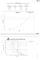
- the present invention relates to a method for gas phase application of chlorine dioxide within an enclosed volume that comprises the steps of: climatizing the enclosed volume to a relative humidity equal to x (%); generating chlorine dioxide gas; and introducing the chlorine dioxide gas into the enclosed volume at CT value of chlorine dioxide equal to y (ppm v -hrs), wherein y is equal to 6 x 2 . 870 x + 32100 ⁇ 1000, x being a number between 5 and 56 equal to the % RH.
- the present invention further relates to a method for gas phase application of chlorine dioxide within an enclosed volume that comprises the steps of: climatizing the enclosed volume to achieve a relative humidity (RH) in the range of about 5% to about 56%, generating chlorine dioxide gas; and introducing the chlorine dioxide gas at a concentration ranging from 25 ppm v to 10,000 ppm v for the appropriate time into the enclosed volume to achieve a CT value of chlorine dioxide equal to y (ppm v -hrs); wherein y is equal to 6 x 2 . 870 x + 32100 ⁇ 1000, x being a number between 5 and 56 equal to the % RH.
- RH relative humidity
- the present invention also relates to a method for gas phase application of chlorine dioxide within an enclosed volume that comprises the steps of: climatizing the enclosed volume to achieve a relative humidity (RH) in the range of about 5% to about 56%, generating chlorine dioxide gas; and introducing the chlorine dioxide gas under specified conditions of chlorine dioxide gas concentration and contact time, the specified conditions being effective to eliminate contaminants within the closed volume, and further to mitigate corrosion within the enclosed volume during the gas phase application.
- RH relative humidity
- CT concentration-time
- the enclosed volume is climatized to achieve a relative humidity (RH) in the range of about 5% to about 56%, preferably about 35% to about 53%, more preferably about 40% to about 52%, still more preferably about 45-50%, most preferably about 45% to about 48%.
- RH relative humidity
- Climatizing the enclosed volume is carried out at a temperature of about 10°C (50°F) to about 32°C (90°F), preferably about 18°C (65°F) to about 29°C (85°F).
- "Elimination of contaminants” is defined as eliminating at least 95% of contaminants, or preferably eliminating at least 98% of contaminants, or more preferably eliminating at least 99% of contaminants.
- the contaminants within the enclosed volume may be selected from the group consisting of: bacteria, spores, molds, mycotoxins, allergens, insects, larvae, arachnids, lizards, and combinations thereof.
- the enclosed volume may include objects selected from the group consiating of metallic objects, non-metallic objects, and combinations thereof.
- Metallic objects within the enclosed volume may be formed from metals selected from the group consisting of steel, aluminum, iron, copper, chromium, lead, and combinations thereof.
- Non-metallic objects may be formed from materials selected from the group consisting of wood, brick, stone, cinder concrete, ceramic tile, ceiling tile, carpet, woven fabric, and combinations thereof.
- the chlorine dioxide gas is introduced into the enclosed volume at a concentration of about 25 ppm v to about 10,000 ppm v , preferably about 500 ppm v to about 30,000 ppm v .
- CT concentration-time
- typical chlorine dioxide concentrations are in the range of 500 to 3000 ppmv, and exposure times are typically about 8 to 12 hours.
- the target set points for each desired % RH level were as follows: Target %RH Reheat Column/Chamber Temperature (°C) Chamber H 2 O Bath (°C) Stripper Column Temperature (°C) Stripper Column H 2 O Bath (°C) 45 21.1 (70 °F) 20 8.9 (48 °F) 0.5 55 21.1 (70 °F) 20 11.7 (53 °F) 7 65 21.1 (70 °F) 20 14.4 (58 °F) 11
- the stripper column temperature was lowered. If the %RH needed to be raised, the stripper column temperature was raised. These temperature adjustments were done using the stripper column H 2 O bath. The opposite holds true for the reheat column/chamber. If the %RH needed to be lowered, the reheat column temperature was raised. If the %RH needed to be raised, the reheat column temperature was lowered. One must keep in mind that adjusting this set-point also affects the chamber temperature. All temperature adjustments were done using the reheat column/chamber H 2 O bath.
- both water baths were turned on and adjusted to desired set-points as set forth above.
- the stripper column pump and chamber blowers were turned on.
- the stripper column was filled with cold tap water up to the drain line and the chamber hatch left open as the stripper column H 2 O bath chilled down to its set-point. Typically it took about 2 hours for the water bath to chill down.
- the samples were placed in chamber and the hatch closed.
- ClO 2 tap water was simultaneously emptied from the stripper column while charging it with ClO 2 solution until it reached the drain line and fumigation would begin. While fumigating, the column was periodically charged with fresh ClO 2 to reach desired concentrations and to maintain concentrations.
- the flow rate of chlorine dioxide solution was set at 800 mL/hour.
- a six log kill can be achieved with a concentration-time of chlorine dioxide equivalent to 5100 CT (ppmvhrs).
- a CT of 5100 ppm v hrs is well within the range of acceptable chlorine dioxide levels as established by those of ordinary skill in the art and governmental agencies that set the standards for fumigation using chlorine dioxide. In fact, it is customary for the gas phase application of chlorine dioxide to use a CT of 9000 ppmv-hrs.
- a six log kill was achieved at a RH of approximately 35% using a CT of 9000 ppmv -hrs.
- an emitter may be used with water alone to lower (or raise, in some instances) the relative humidity in the volume requiring remediation. This is done by adjusting the temperature within the system and, in a preferred embodiment, is accomplished as follows.
- lowering the relative humidity in an enclosed space or structure such as a building or home can be accomplished by the use of an emitter and a chiller.
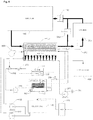
- a volume of water is placed in emitter 100.
- approximately 0.61-0.91 m (2-3 feet) of water is placed in the bottom of emitter 100.
- This water is then passed through chiller 120 to take the temperature of the water down to the appropriate dew point temperature when compared to the temperature of building 140. For example, if the temperature in the building 140 or other enclosed space to be fumigated is 23.9 °C (75°F), a dew point temperature of about 11.1 °C (52°F) is needed in the water.
- the water is initially circulated out of the emitter 100 through a chiller 120 using a pump 260 that continually chills the water.
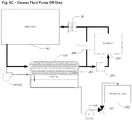
- the chilled water flows back into the emitter through a series of 'condenser' pipes 200 in the air space above the water in the emitter ( Fig. 7A ).
- the target humidity in the enclosed space to be fumigated is reached by passing the air from the building 140 using a fan 130 through emitter 100. Due to the cold water at dew point temperature circulating through the condenser pipes in the emitter, the humidity in the air passed through the emitter 100 will drop as water vapor is condensed out of the air.
- the de-humidified air will then go back into the building 140. This process is continued in a cycle until the target relative humidity in building 140 is achieved, and then fumigation can begin.
- valve configuration (210,220, 230) of the system allows all of the water in the emitter 100 to pass directly through the chiller 120, which brings the water in the emitter 100 down to the required dew point temperature.
- water is kept circulating through the condenser coils 200 in the top of the emitter 100, while air is pumped from the building using a fan 130 through the top space in the emitter, such that air passes over the cold condenser coils 200.
- fumigation can start.
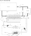
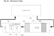
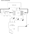
- the valve configuration (220, 230) in the system is then switched over so that the chiller 120 is controlling the temperature of water in a separate tank 110 containing a double wall counter flow heat exchanger 115 ( Fig. 7B ). This is done to avoid having to put the chlorine dioxide solution directly through the chiller 120.
- chlorine dioxide solution is injected into the emitter 100 where the bubbling air through the water in the emitter 100 strips the gas out and then carries it into the building 140.
- the water in the emitter is continuously passed through the heat exchanger 115, which is sitting in the middle tank 110 of cold water that is kept cold by the chiller 120. This maintains the dew point temperature of the water in the emitter.
- the valves in the system are configured for the Climatization Step (7A).
- the water is going directly from the emitter to the chiller and air is passed from the building to the emitter to de-humidify it.
- the valves are configured so that the chiller cools the middle tank of water 110 that holds a heat exchanger 115 to about dew point temperature . To accomplish this, water moves from chiller 120 to middle tank 110 and then back to the chiller 120.
- the valves (210, 220, 230) are configured such that water from the emitter 100 is pumped through the heat exchanger 115 sitting in middle tank 110.
- the water circulating from emitter 100 passes through the heat exchanger in middle tank 110, while the water in middle tank 110 is kept at about dew point by chiller 120.
- the cold water in the middle tank 110 is continuously circulated in a counter flow through the heat exchanger by a small submersible pump 105 in the middle tank 110 for maximum cooling efficiency.
- the system's air loop is under balanced pressure. This is accomplished by the use of fan 130, which draws air (via suction) from building 140 through the emitter 100 and scrubber 280, then back in again.
- fan 130 operates at about 141.6 cubic meters per minute (5000 cubic feet per minute (CFM)).
- blower 150 takes a small amount of air from the building 140 and passes it through the water in emitter 100 in order strip the chlorine dioxide gas. In a preferred embodiment, blower 150 operates at about 2.8 cubic meters per minute (100 CFM).
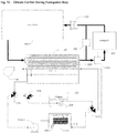
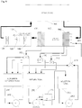
- Fig. 8 water is pumped from the emitter 100 by a pump 250 through a chlorine dioxide generator 170 and into a solution holding tank 180 ( Fig. 8A ). The solution is then pumped from the solution holding tank 180 into the emitter 100 using pump 190 ( Fig. 8B ). Pump 200 is used as a backup pump to increase the flow of solution to the emitter if required. Chlorine dioxide is stripped from the solution in the emitter 100 by means of the blower 150 blowing air through the water in the emitter.
- waste storage tank 160 into which excess fluid can be pumped from the system by pump 250 through valve 240 in order to remove volume from the system.
- the entire system in Figs. 6-8 is designed to both pump gas into the building and to maintain the target relative humidity within the building. In one embodiment, this is accomplished by keeping the air in the emitter at the dew point temperature. According to this embodiment, when the air enters the building, it will be warmed because of the higher temperature in the building (e.g., about 23.9° C (75° F)). As the temperature of the air from the emitter rises, the relative humidity will drop. In other words, the air in the emitter is at dew point so that any gas that is bubbled through and pumped into the building is essentially at saturation (100% RH). When this enters the building and warms up, the humidity will drop to the target RH
- the gas is removed from the air in the building. This is achieved by closing damper 300 and opening damper 290 and passing the air through a scrubber 280.
- the scrubber can be a container of activated carbon, or a liquid scrubber using an alkalizing and dechlorinating agent or other functional chemistry (e.g., ascorbic acid).
- the air is continuously circulated through the scrubber until the measured concentration of chlorine dioxide gas in the air in the structure has been reduced to below the target concentration.
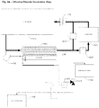
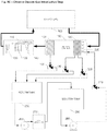
- Fig. 9 schematically illustrates a further embodiment of the invention.
- lowering the relative humidity in an enclosed space or structure such as a building or home, and introducing chlorine dioxide gas to the structure can be accomplished by the use of an emitter/scrubber, which functions as both an emitter and a scrubber, and an air handling unit which functions both as a dehumidifier and air reheat unit.
- an emitter/scrubber which functions as both an emitter and a scrubber
- an air handling unit which functions both as a dehumidifier and air reheat unit.
- air is pulled under suction from the structure 100, through the emitter/scrubber 150, through the air handling unit 110 and recirculated back into the structure by means of a fan 120.
- the fan 120 which may be part of or separate from the air handling unit, may be placed at any point in the air re-circulation loop.
- a refrigeration coil 140 is set at a temperature sufficient to remove moisture from the air and thereby achieve the target relative humidity.
- the air passing over the coil 140 is effectively chilled to a temperature near to that of the coil.
- the relative humidity of the air leaving the coil is approaching 100% at this point.
- the air is reheated to the temperature of the air in the building with a heating coil 130.
- the reheat coil may be electrical, or may use waste heat from the refrigeration process, or a combination of both.
- the refrigeration and reheat capacity of the air handling unit may be sized to achieve the desired target relative humidity with one pass of the air through the air handling unit, or to achieve the desired target relative humidity after two or more passes of the air through the air handling unit.
- fan 120 which draws air (via suction) from the structure 100, through the emitter/scrubber 150, through the air handling unit 110, and then back into the structure.
- fan 120 operates at a preferred flow rate of about 85 cubic meters per minute (3000 cubic feet per minute (CFM)). Fan 120 may operate at any flow rate provided that it does not exceed the air flow rate design parameters of the refrigeration coil 140 or the reheat coil 130.
- first water is added to the return tank 250 in a sufficient volume to meet the needs of the chlorine dioxide generation process.
- the preferred volume is about 946.4 liters (250 US gallons).
- Pump 260 is switched on to pump the water from return tank 250, through the chlorine dioxide generator 270, and into the solution tank 290. This continues until all the water in return tank 250 has been transferred through the generator 270 into the solution tank 290.
- the air flow through the emitter/scrubber 150 and air handling unit 110 is maintained by fan 120 with both the refrigeration coil 140 and the reheat coil 130 functioning, so that any humidity introduced in the air stream by the emitter/scrubber is removed before the air is returned to the structure.
- the emitter/scrubber first has to be configured to function as an emitter.
- the valves 180, 190 and 200 on the emitter/scrubber drains are configured so that any liquid draining from the emitter/scrubber drains back into the return tank 250.
- Valve 210 is then configured so that fluid from pump 280 is directed through the spray header bar 220 in the emitter/scrubber 150.
- pump 280 With air flowing through the emitter/scrubber, pump 280 is turned on to send chlorine dioxide solution to the emitter/scrubber through the spray head 220.
- An impingement bank 160 in the emitter/scrubber ensures intimate contact between the chlorine dioxide solution and the air. This contact enables chlorine dioxide gas to be released from the solution and enter the air stream.
- Depleted chlorine dioxide solution drains from the emitter/scrubber 150 back into the return tank 250 via valves 190 and 200.
- a mist eliminator 170 is utilized to remove water droplets from the air leaving the emitter scrubber. Liquid taken from the air by mist eliminator 170 drains back into the return tank 250 via valve 180.
- the depleted chlorine dioxide solution is then pumped from the return tank 250 through the chlorine dioxide generator 270 by pump 260 into the solution tank 290. This recharges the spent solution with chlorine dioxide ready for return to the emitter/scrubber by pump 280. This process continues until the required concentration of chlorine dioxide has been reached in the structure and held for the required time at that concentration to achieve the target CT.
- pump 280 When the required concentration of chlorine dioxide has been maintained in the structure for the required time period to achieve the target CT, pump 280 is turned off and the scrubbing process to remove the chlorine dioxide gas from the structure can commence.
- the air flow through the emitter/scrubber 150 and air handling unit 110 is maintained by fan 120 with both the refrigeration coil 140 and the reheat coil 130 functioning, so that any humidity introduced in the air stream by the emitter/scrubber is removed before the air is returned to the structure.
- the emitter/scrubber 150 has to be configured for use as a scrubber.
- Valves 180, 190 and 200 on the emitter/scrubber drains are configured so that any fluid from the emitter/scrubber drains into the scrubber solution tank 220.
- Valve 210 is configured so that the flow from pump 230 is delivered to the spray head 220 in the emitter/scrubber.
- the scrubber tank 220 is filled with sufficient scrubber solution and at a concentration required to remove the quantity of chlorine dioxide gas that remains in the structure.
- the scrubber solution may be an alkalizing and dechlorinating agent or other chemical agent suitable for scrubbing chlorine dioxide gas from an air stream.
- Pump 230 is switched on to pump scrubber fluid via valve 210 to the spray header 220 in the emitter/scrubber 150.
- An impingement bank 160 in the emitter/scrubber ensures intimate contact between the air stream containing chlorine dioxide gas and the scrubber solution. This contact enables chlorine dioxide gas to react with the scrubber solution and be removed from the air stream.
- Scrubber solution drains from the emitter/scrubber impingement bank 160 to the scrubber solution tank 220 via valves 190 and 200.
- a mist eliminator 170 is utilized to remove water droplets from the air leaving the emitter/scrubber. Liquid taken from the air by mist eliminator 170 drains back into the scrubber solution tank 220 via valve 180.
- the scrubber solution is pumped through the emitter/scrubber, and the air from the structure is recirculated through the emitter/scrubber until the measured concentration of chlorine dioxide gas in the air in the structure has been reduced to below the target concentration.
- the return tank 250, solution tank 290 and scrubber solution tank 230 are sized for sufficient volume to contain all the introduced liquids.
- the system may need to be configured to increase the relative humidity to a target value in the enclosed space to be fumigated.
- chlorine dioxide is not stable at partial pressures over 83 millimeters of mercury, it is not available for purchase in high-pressure gas cylinders. Therefore chlorine dioxide gas must be generated at the decontamination site for subsequent introduction into an enclosed space to be fumigated.
- chlorine dioxide solutions can be produced by treatment of chlorite salt solutions (e.g. NaClO 2 ) with an acid solution to produce acidic solutions that contain ClO 2 , which can be then be flushed as a gas into water to produce aqueous ClO 2 .
- chlorite salt solutions e.g. NaClO 2
- Other precursors such as sodium chlorate can also be used.
- the present invention provides a process that comprises producing chlorine dioxide by using an apparatus such as a chlorine dioxide generator, e.g. as disclosed and claimed in U.S. Pat. No. 6,468,479 .
- the chlorine dioxide is generated either directly as a gas, or preferably as an aqueous (or other suitable liquid carrier) chlorine dioxide mixture.
- the generator is preferably run using an excess of sodium chlorite to reduce the possibility of generating chlorine gas as an impurity.
- Other generally accepted methods for generating chlorine dioxide can be found in, for example, U.S. Patent Pub. No. 2006/0068029 ( U.S. Pat. App. No. 11/131021 ).
- the same equipment described in the above climatization step and shown in Figs. 6-8 is used to a) introduce the chlorine dioxide gas into the volume requiring remediation, b) distribute the introduced chlorine dioxide gas within the volume, and c) maintain the chlorine dioxide gas within the volume at a concentration and for a sufficient duration to permit the gas to penetrate included contents as required for fumigation.
- the generated chlorine dioxide is transferred directly or alternatively, indirectly via a storage tank, to the emitter.
- the emitter is an apparatus such as the stripper discussed above and shown in Figs 6-8 .
- the emitter is operated to maintain the gaseous chlorine dioxide concentration substantially below the explosion limit of chlorine dioxide in the air.
- the emitter is a combined emitter/scrubber as described above and shown in Fig. 9
- the relative humidity must be maintained at the target percentage for the particular application. Therefore, the climatization to achieve the target relative humidity (i.e. via de-humidification or humidification) and the remediation are performed simultaneously using the same apparatus by the appropriate adjustment in the temperature of chlorine dioxide solution, or by using an air handling unit that combines dehumidification and air reheating.
- illumination levels may also be reduced within the enclosed space, preferably to substantial darkness, to minimize the decomposition of chlorine dioxide to chlorine.
- the process is monitored with the use of an infrared camera or similar device. Temperature, relative humidity, concentration of decontamination agent, and contact time typically will be measured and recorded throughout the decontamination process.
- variable generation rate of chlorine dioxide gas is initiated.
- the initial rate is high to provide sufficient chlorine dioxide to penetrate the various materials within the volume requiring remediation.
- This rate is predetermined to accommodate the material demand as well as to provide the initial charge of the volume requiring remediation to a predetermined chlorine dioxide residual level.
- the chlorine dioxide generation rate is then reduced appropriately to maintain the predetermined chlorine dioxide concentration in the air of the volume requiring remediation for a predetermined time. This can be achieved by various means, for example, lowering the concentration of chlorine dioxide in the solution that is fed to the emitter, or lowering the flow rate of the chlorine dioxide solution to the emitter.
- the chlorine dioxide gas concentration is determined to compensate for the decay or loss rate from the volume requiring remediation.
- the volume requiring remediation is preferably to be at slightly negative pressure to areas outside of it, and the volume may be sealed off through the use of a strippable sealant, for example, a hardenable foam.
- the volume to be remediated can be enclosed within a substantially light impervious tent while undergoing remediation so as to avoid light-induced degradation of the introduced chlorine dioxide gas.
- the tent is substantially impervious to gas.
- the generator, storage and emitter are purged with fresh water. Subsequently the water may be injected with an alkalizing and dechlorinating agent or other agent that will scrub the chlorine dioxide. This scrubbing solution is then fed to the emitter and with the blowers still in operation, and the emitter begins to scrub chlorine dioxide out of the environmental air composition within the volume that has been remediated.
- the chlorine dioxide can be scrubbed from the environmental air by passing the air through a separate scrubber system containing water injected with an alkalizing and dechlorinating agent or other agent that will scrub the chlorine dioxide. This process is continued until the environmental air composition within the volume that has been remediated is returned to acceptable limits for reopening the exterior environment to re-habitation.
- the emitters can be located inside or outside of the volume requiring remediation. However, it is highly preferred to locate the emitter inside the volume requiring remediation, since then no contaminated air is allowed to leave the volume requiring remediation.
- a 232.2-square meters (2500-square foot) building structure was encapsulated and prepared for treatment with chlorine dioxide gas.
- the structure was maintained under a negative pressure by withdrawing from 50 to 100 CFM of air from the structure though out the treatment process.
- the withdrawn air was scrubbed though carbon filters to prevent the discharge of chlorine dioxide.
- Temperature and relative humidity were monitored at six locations throughout the structure.
- An external six ton HVAC system was connected to the home to provide temperature and humidity control.
- a six thousand 1b per day (2721.5 kg/day) chlorine dioxide system with the appropriately sized gas strippper was used to apply chlorine dioxide to the building structure.
- Chlorine dioxide gas was added to the structure to achieve a concentration ranging from 2800 to 3800 ppmv throughout the structure.
- chlorine dioxide was added to the structure to maintain these concentrations.
- the relative humidity was maintained within the structure between 32 and 45%.
- the concentration-time (CT) of chlorine dioxide in the structure was 37,000 ppmv/hours.
- a structure was prepared for fumigation with chlorine dioxide gas by enclosing the structure within an envelope, installing a scrubbing system upon the structure to maintain a negative pressure within the envelope, and installing temperature and humidity control equipment to maintain environmental levels.
- the structure had a footprint of approximately 297.3 square meters (3200 square feet) and a volume of 1500.8 cubic meters (53000 cubic feet).
- Chlorine dioxide was added continuously for about 14 hours to maintain an average concentration of about 3800 ppmv.
- the total treatment of the structure was an average of 52,000 ppmv hours of chlorine dioxide.
- the drywall Prior to the treatment of 10 locations, the drywall was sampled to determine the presence of bacterial growth by culture for anaerobic, aerobic, and sulfate reducing bacteria. All locations exhibited growth on the wallboard surface, within the front and back wallboard paper, and within the core of the gypsum. All locations exhibited bacterial growth. Six log spore strips were inserted deep into the wall cavities prior to the fumigation. All wall penetrations made during sampling were sealed with "plumber's plugs" prior to fumigation.
- Post fumigation no bacterial growth was observed at any of the sample locations. All spore strips were completely inactivated. Post fumigation numerous types of insects and arachnids, including ants, flies, larvae, bees, termites, and spiders were observed dead throughout the structure. Numerous geckos on the walls and floors within the fumigated volume were also found dead post fumigation.
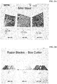
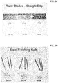
- Metals such as exposed, scuffed mild steel and high carbon steel known to be sensitive to chlorine dioxide fumigation at high humidities were examined at six hours, thirty days, and sixty days following fumigation. No evidence of corrosion due to the fumigation was observed.
- Each of the structures was fumigated with chlorine dioxide gas at concentrations from 1500 ppmv to 4500 ppmv chlorine dioxide.
- the chlorine dioxide concentration -time (CT) ranged from 9000 ppm v hours to 54,000 ppm v hours. All of the structures were inspected immediately post fumigation and 30 days after fumigation. No corrosion or rusting was observed in any of the structures. All of the highly sensitive materials were corrosion-free post fumigation on the immediate and 30 day evaluations.
- Humidity measured in the structures prior to fumigation ranged from 65% to 80%. Immediately prior to fumigation, the relative humidity levels were adjusted to 48% or less using a humidity control system. The process used a cooling coil to remove moisture from the air and a reheating coil to maintain temperature within the structure.
- the structures were purged with outside air for a period of 72 hours.
- the purge air temperature ranged from 18.3 °C (35°F) to 23.9 °C (75°F) and from 40% to 85% relative humidity.
- Penetration of chlorine dioxide throughout the structure was verified by culture tests of the drywall core and by the insertion of "spore strips" within the structure walls. Chlorine dioxide kill, and thus penetration, was demonstrated on all of the core samples and all of the inserted spore strips on all of the tests and all of the structures.
- ClO 2 fumigation process One technology that shows great promise for solving the Chinese wallboard problem is a gaseous chlorine dioxide (ClO 2 ) fumigation process originally developed by Sabre Technical Services, LLC (Sabre) while assisting USEPA and the US Postal Service (USPS) in devising a technical solution to widespread Bacillus anthracis (i.e. anthrax) contamination present in buildings following the anthrax attacks of 2001.
- Sabre's ClO 2 fumigation technology was used to eliminate anthrax contamination from the Hart Senate Office Building and USPS Curseen-Morris Processing and Distribution Center (P&DC) in Washington, DC, the USPS Trenton P&DC in Hamilton Township, New Jersey and the former American Media, Inc. Building in Boca Raton, Florida.
- the size of these ClO 2 fumigation applications ranged from a low of 2831.7 cubic meters (100,000 cubic feet (ft 3 )) to a high of over 396436 cubic meters (14 million ft 3 ).
- a major complication in determining success of ClO 2 in eliminating reduced-sulfur compounds from an affected structure is the difficulty of measuring and analyzing these gases at the low concentrations they are present at within the structure.
- Sabre used various surrogate measures to document the efficacy of ClO 2 gas in ridding the test structure of reduced-sulfur compounds.
- atrophaeus species is widely recognized as being the most difficult to inactivate with ClO2 gas. Pervasive inactivation of BIs in "hard to reach" areas of the structure (i.e. inside wall cavities) thus indicates that pervasive oxidation of reduced- sulfur compounds also occurred throughout the structure.
- Reduced- sulfur compounds odors are extremely noxious and can be detected by the human olfactory (i.e. odor) sense at levels which are at or below the detection limits of sophisticated analytical instruments.
- the olfactory senses of both Sabre personnel and independent observers were employed both pre- and post-treatment to gauge the effectiveness of ClO2 in ridding the test structure of reduced- sulfur compound odors.
- This 225.6 square meters (2,429 square foot) two-story home consists of 3 bedrooms, 3.5 baths, a kitchen, grand room, dining room, laundry room and an attached 2-car garage.
- This home also has an adjacent 26.6 square meters (286 square foot) guest cabana consisting of 1 bedroom, 1 bathroom and a small kitchen.
- the main home and guest cabana are connected by a private courtyard with a screen ceiling enclosure, brick foundation and small spa.
- the entire structure, including main home, guest cabana and private courtyard was enclosed with impermeable polyethylene sheeting material during the fumigation to prevent release of ClO 2 gas to the surrounding environment.
- Pre- and post-treatment SRB samples were collected from wallboard material throughout the structure to assess efficacy of the ClO2 gas in inactivating bacteria present within them, and thus oxidizing any reduced-sulfur compounds.
- BI spore strips were also placed in representative locations throughout building wall cavities to document that pervasive gas penetration occurred throughout the structure.
- Temperature and RH -- Temperature and RH conditions within the structure were monitored throughout the fumigation at four representative locations. Each monitored location was deemed to be a potential problem area for controlling temperature and RH conditions based on the home's heating, ventilation and air conditioning (HVAC) system and airflow movement characteristics. Selected monitoring locations were in the 1st floor master suite closet; inside the attic access point in the garage; in the guest cabana kitchen; and inside the attic access point in the 2nd floor suite #2 closet.
- HVAC heating, ventilation and air conditioning
- the target temperature and RH conditions chosen for the fumigation were a temperature of 26. 6°C ⁇ 2.8°C (80oF ⁇ 5° F) and an RH level of 45% ⁇ 5% at all monitoring locations.
- Temperature and RH levels were monitored through use of HOBO® Model U 12-011 TEMP/RH Data Loggers manufactured by Onset Computer Corporation.
- the instrument temperature measuring range is -20 to 70°C (-4 to 158°F) with an accuracy of ⁇ 0.35°C ( ⁇ 0.63 °F).
- the RH measuring range is 5% to 95% with an accuracy of ⁇ 2.5 %. Temperature and RH measurements were monitored on a real-time basis and logged at 5-minute intervals throughout the fumigation process.
- ClO2 Concentrations and CT Values -- ClO2 concentration levels were monitored throughout the fumigation process at the same four representative locations selected for temperature and RH monitoring. These locations were, again, selected based on knowledge of the home's HVAC systems and airflow movement characteristics.
- the target ClO 2 parameters selected for this project were an average concentration of 500 ppm v or more and a CT value not less than 2,000 ppmv-hours nor more than 9,000 ppmv-hours at all monitoring locations. Monitoring of ClO 2 concentrations began shortly after the gas was first introduced into the structure and continued at periodic intervals throughout the fumigation process.
- HDPE tubing 0.63cm (one-quarter inch) inside diameter high-density polyethylene (HDPE) tubing.
- the HDPE tubing was run from the four designated monitoring locations to a central sampling manifold located outside the building in a mobile laboratory facility. Samples were collected and analyzed by trained technicians. Air flowed continuously to the sampling manifold so that samples represented existing conditions within the building at the time they were taken. A vacuum pump was placed on the downstream side of the sampling manifold to move air through the system and return it to the structure on a continuous basis throughout the fumigation process.
- Samples were collected from the sampling manifold via impingement of two liters of air at a flow rate of 1.0 liter per minute through 15 milliliters of a strongly buffered pH 7 potassium iodide solution (modified US Occupational Safety and Health Administration Method ID126SGX). Once collected, samples were analyzed by colorimetric titration, using a 0.1 normal sodium thiosulfate solution as the titrant (modified American Water Works Association Method 4500-ClO 2 -E and modified 2-step version of same).
- a fumigation ClO 2 CT dose "clock” was started for each of the four co-located monitoring points when temperature and RH conditions had equilibrated in their desired ranges and gas introduction into the structure had begun. Once started, each CT clock accumulated ClO 2 exposure "credit" until the target dose level had been achieved at each monitoring location, at which time the fumigation was deemed complete.
- SRBs The efficacy of ClO 2 gas in eliminating SRBs from Chinese wallboard material was evaluated by collecting samples of unpainted wallboard paper located inside wall cavities of the home prior to, and immediately after, ClO 2 exposure. Unpainted wallboard paper from wall cavities was chosen for SRB testing because preliminary laboratory work done at Sabre's Slingerlands, NY laboratory facility had shown SRBs to be concentrated in this media.
- Pre-treatment wallboard paper samples were collected by drilling a 5.08cm (two- inch) circular core at selected wall and ceiling locations. To avoid damaging vapor barriers present within the home, samples were not collected from any bathroom or laundry room locations. Sample locations were selected to be representative wall cavities within the structure most likely to contain conditions conducive to SRB growth. In total, 20 sample locations were selected. Nine were wall cores and eleven were ceiling cores.
- the wallboard holes created through SRB sampling were each sealed using a 5.08cm (two-inch) rubber expansion plug in order to ensure that ClO 2 gas would not penetrate into wall cavities as a consequence of sampling activities.
- Post-treatment wallboard paper samples were collected by drilling an identical 5.08cm (two-inch) circular core approximately one inch away from each of the 20 pre- treatment sample locations.
- BI Spore Strips - BI spore strips, each containing an approximate 2.5 x 10 3 titer of B. atrophaeus spores, were placed within wall cavities of the structure at the same 20 locations where wallboard samples had been collected, prior to insertion of the 5.08cm (2-inch) expansion plugs.
- the B. atrophaeus species was selected due to its historical use as a biological indicator for ClO 2 fumigations
- Spore strips are thin cellulose pads that have been impregnated with a defined titer of bacterial spores. Each spore strip is encased in a Tyvek® pouch to allow for effective penetration of fumigant gas yet protect the strip from contamination by external sources.
- the BIs were obtained from SGM Biotech Inc., 10 Evergreen Drive, Suite E, Bozeman, MT (Lot # ACD-113e). All BIs were supplied from the same product batch in order to ensure uniformity in spore titer. Relevant production QA/QC data for the specific lot number have been kept on file for future reference.
- BIs were retrieved promptly following fumigation and sent to Sabre's Slingerlands, NY laboratory facility for analysis.
- Each spore strip was aseptically placed in a growth media tube containing 15 milliliters of trypticase soy broth (BD Diagnostics product #221823, Lot # 7337460) and incubated at 37°C. Spore strips were evaluated daily for the presence or absence of indicator organism growth for a total of seven days.
- Corrosivity potential was assessed by observation of typical metal items present within the structure (e.g. screws, door hinges, HVAC system components, etc.).
- Several pieces of copper pipe were also placed on the cafe countertop for the duration of fumigation to verify that ClO 2 would not cause any adverse effects such as corrosion or discoloration.
- Each piece of copper was "scuffed” clean prior to fumigation to ensure that any changes in the metal due to ClO 2 exposure would be readily recognizable. Photographs were taken of the copper pipe pieces before and after treatment to document visual observations made.
- Bleaching potential of ClO 2 was assessed by observation of carpet color and brightness throughout the structure both pre- and post-treatment. A piece of carpeting was also removed from a closet within the structure prior to fumigation and used for direct visual comparison with treated carpet following completion of the process.
- Odor levels emanating from within the structure were observed both pre- and post-treatment for the "putrid" characteristic commonly associated with reduced- sulfur gases such as hydrogen sulfide, carbonyl sulfide and carbon disulfide that have been definitively shown by an FDOH study as being released from Chinese wallboard.
- Positive control BIs were submitted to the Sabre laboratory for viability testing along with the fumigated BIs in a ratio of approximately one positive control sample for every 10 treated samples, for a total of two positive controls. Positive controls are untreated (i.e., not fumigated) BIs of identical composition that are submitted to the laboratory along with the exposed BIs. Positive controls provide evidence of BI product quality as well as evidence that appropriate conditions for growth of the surrogate test organism were achieved. The positive control samples were handled, packaged and shipped in the same manner as the actual samples from the building, except that the positive controls were not subjected to the fumigant gas.
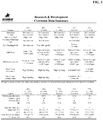
- Temperature & RH -- Raw temperature and RH data were exported from the HOBO® data loggers into a Microsoft Corporation Excel® spreadsheet for purposes of calculating mean temperature and RH levels for each monitoring location. These mean temperature and RH values ( ⁇ one standard deviation) are shown in Table 1.
- the SRB growth data indicated a widespread presence of SRBs within the unpainted wallboard paper prior to fumigation. Twelve of 20 sample locations were found to be positive for SRBs prior to ClO 2 treatment. Following treatment, all 20 locations were determined to be negative for SRB growth.
- the ClO 2 fumigation process was shown capable of inactivating SRBs present within wallboard material, as well as BI spore strips embedded within wall cavities, thereby demonstrating the ability of ClO 2 gas to completely permeate an affected structure and oxidize reduced sulfur compounds at the CT values employed. In addition, it was demonstrated that ClO 2 would not cause unacceptable changes within a treated structure in terms of metal corrosion or material bleaching.
Landscapes
- Health & Medical Sciences (AREA)
- Animal Behavior & Ethology (AREA)
- Public Health (AREA)
- Veterinary Medicine (AREA)
- Epidemiology (AREA)
- Life Sciences & Earth Sciences (AREA)
- General Health & Medical Sciences (AREA)
- Chemical & Material Sciences (AREA)
- Organic Chemistry (AREA)
- General Chemical & Material Sciences (AREA)
- Chemical Kinetics & Catalysis (AREA)
- Inorganic Chemistry (AREA)
- Apparatus For Disinfection Or Sterilisation (AREA)
- Agricultural Chemicals And Associated Chemicals (AREA)
- Catching Or Destruction (AREA)
Claims (11)
- Verfahren für eine Gasphasenanwendung von Chlordioxid in einem geschlossenen Raum, wobei das Verfahren die folgenden Schritte umfasst:
Klimatisieren des geschlossenen Raums auf eine Temperatur von 10 °C (50 °F) bis 32,2 °C (90 °F), um eine relative Luftfeuchtigkeit (RH) von 5 % bis 56 % zu erreichen; Erzeugen von Chlordioxidgas und Einführen des Chlordioxidgases in den geschlossenen Raum zu einer Konzentrationszeit (CT) gleich y (ppmv-hrs), mit y = 6x2 - 870x + 32100 ± 1000, wobei x der prozentualen RH entspricht, wobei die CT die zeitlich gewichtete mittlere Chlordioxidkonzentration multipliziert mit der Expositionszeit ist. - Verfahren nach Anspruch 1, wobei die RH im Bereich von 35 % bis 53 % liegt.
- Verfahren nach Anspruch 1, wobei die RH im Bereich von 45 % bis 48 % liegt.
- Verfahren nach Anspruch 1, wobei die RH im Bereich von 45 % bis 55 % liegt.
- Verfahren nach einem der Ansprüche 1 bis 4, wobei der geschlossene Raum Kontaminationsstoffe enthält, die ausgewählt sind aus der Gruppe bestehend aus:
Bakterien, Sporen, Schimmel, Mycotoxinen, Allergenen, Insekten, Larven, Arachniden, Echsen und Kombinationen davon. - Verfahren nach Anspruch 5, wobei die Kontaminationsstoffe Sulfat reduzierende Bakterien sind.
- Verfahren nach einem der Ansprüche 1 bis 6, wobei das geschlossene Volumen Objekte umfasst, die aus Metallen gebildet sind, die ausgewählt sind aus der Gruppe bestehend aus Stahl, Aluminium, Eisen, Kupfer, Chrom, Blei und Kombinationen davon.
- Verfahren nach einem der Ansprüche 1 bis 7, wobei das Einführen des Chlordioxidgases folgendes umfasst: Einführen des Chlordioxidgases in den geschlossenen Raum mit einer Konzentration von 25 ppmv bis 10.000 ppmv.
- Verfahren nach Anspruch 8, wobei das Chlordioxidgas in den geschlossenen Raum mit einer Konzentration von 500 ppmv bis 3.000 ppmv eingeführt wird.
- Verfahren nach einem der Ansprüche 1 bis 9, wobei das Klimatisieren des geschlossenen Raums auf einer Temperatur von 18,3 °C (65 °F) bis 29,4 °C (85 °F) durchgeführt wird.
- Verfahren nach Anspruch 5, wobei der Kontaminationsstoff Bacillus atrophaeus ist.
Applications Claiming Priority (2)
| Application Number | Priority Date | Filing Date | Title |
|---|---|---|---|
| US18429809P | 2009-06-04 | 2009-06-04 | |
| PCT/US2010/032812 WO2010141169A2 (en) | 2009-06-04 | 2010-04-28 | Decontamination of enclosed space using gaseous chlorine dioxide |
Publications (3)
| Publication Number | Publication Date |
|---|---|
| EP2437795A2 EP2437795A2 (de) | 2012-04-11 |
| EP2437795A4 EP2437795A4 (de) | 2014-11-26 |
| EP2437795B1 true EP2437795B1 (de) | 2019-04-24 |
Family
ID=43298388
Family Applications (1)
| Application Number | Title | Priority Date | Filing Date |
|---|---|---|---|
| EP10783758.5A Not-in-force EP2437795B1 (de) | 2009-06-04 | 2010-04-28 | Dekontaminierung geschlossener räume mithilfe von gasförmigem chlorindioxid |
Country Status (7)
| Country | Link |
|---|---|
| US (2) | US8192684B2 (de) |
| EP (1) | EP2437795B1 (de) |
| JP (1) | JP5823957B2 (de) |
| CN (1) | CN102458487B (de) |
| AU (1) | AU2010257064B2 (de) |
| CA (1) | CA2764138C (de) |
| WO (1) | WO2010141169A2 (de) |
Families Citing this family (25)
| Publication number | Priority date | Publication date | Assignee | Title |
|---|---|---|---|---|
| US7571676B2 (en) * | 2004-11-19 | 2009-08-11 | Purdue Research Foundation | Apparatus and method for reducing microorganisms on produce using chlorine dioxide gas |
| US8931234B2 (en) * | 2012-01-24 | 2015-01-13 | David J. Stork | Chinese drywall fix |
| WO2014055851A1 (en) * | 2012-10-05 | 2014-04-10 | Structural Group, Inc. | System and method for internal pressurized gas drying of concrete |
| US9227156B2 (en) * | 2012-11-09 | 2016-01-05 | Chemtreat, Inc. | Method and apparatus for reactive gas remediation |
| EP2955155A4 (de) * | 2013-02-05 | 2016-11-02 | Taiko Pharmaceutical Co Ltd | Verfahren zum einfangen von chlordioxidgas, verfahren zur messung der konzentration von chlordioxidgas und mittel zum einfangen von chlordioxidgas |
| US20140271355A1 (en) * | 2013-03-15 | 2014-09-18 | Sabre Intellectual Property Holdings Llc | Apparatus and process for focused gas phase application of biocide |
| KR101465563B1 (ko) * | 2013-08-26 | 2014-11-26 | (주)옥시테라피 | 습윤이산화염소가스를 이용한 멸균장치 및 멸균방법 |
| JPWO2015159578A1 (ja) * | 2014-04-16 | 2017-04-13 | アース・バイオケミカル株式会社 | 衛生管理方法 |
| CN104174270A (zh) * | 2014-08-04 | 2014-12-03 | 龚晓 | 去除可挥发性有机污染物和/或致病性微生物的方法 |
| US10161895B2 (en) | 2014-12-23 | 2018-12-25 | 3M Innovative Properties Company | Electronic moisture sensor |
| US11079340B2 (en) | 2014-12-23 | 2021-08-03 | 3M Innovative Properties Company | Methods of monitoring wetness utilizing a resonant circuit |
| US10171975B2 (en) | 2015-01-19 | 2019-01-01 | Lennox Industries Inc. | Efficient distribution of heating, ventilation, and air conditioning functionality |
| JP2017012400A (ja) * | 2015-06-30 | 2017-01-19 | 株式会社大林組 | 除染方法及び除染システム |
| EP3153184A3 (de) * | 2015-09-16 | 2017-07-12 | Aqua Ecologic | Verfahren und system zur desinfektion mit chlordioxidgas |
| AR107088A1 (es) | 2015-12-18 | 2018-03-21 | Sabre Ip Holdings Llc | Métodos de extracción de aceites y grasas de material sólido usando dióxido de cloro |
| US10233100B2 (en) | 2016-06-21 | 2019-03-19 | Sabre Intellectual Property Holdings Llc | Methods for inactivating mosquito larvae using aqueous chlorine dioxide treatment solutions |
| CN106075510B (zh) * | 2016-08-02 | 2022-04-01 | 湖北荷普药业股份有限公司 | 一种气体灭菌设备 |
| WO2019004137A1 (ja) * | 2017-06-26 | 2019-01-03 | アース製薬株式会社 | 二酸化塩素ガスによる除染方法 |
| JP6961550B2 (ja) * | 2018-08-03 | 2021-11-05 | 株式会社アマテラ | 二酸化塩素ガスの発生消滅方法および二酸化塩素ガス発生消滅用キット |
| US12329159B2 (en) | 2018-12-13 | 2025-06-17 | ProKure Solutions, LLC | Systems and methods for use of chlorine dioxide in cultivation and post-harvest applications |
| CN111101118B (zh) * | 2019-11-29 | 2024-08-13 | 昆山东威科技股份有限公司 | 一种回流槽及具有回流槽的装置 |
| US12252681B2 (en) * | 2020-08-18 | 2025-03-18 | Upside Foods, Inc. | Systems, devices, and methods for sterilizing bioreactors and culture media |
| US12201738B2 (en) | 2021-08-16 | 2025-01-21 | ClorDiSy Solutions, Inc. | System for converting an existing ethylene oxide vacuum sterilizer into a chlorine dioxide vacuum sterilizer |
| US12359324B2 (en) * | 2022-03-28 | 2025-07-15 | Cupod Llc | System for sterilizing equipment, associated method, and chlorine dioxide gas generating device for use with same |
| JP7668999B2 (ja) * | 2023-02-20 | 2025-04-28 | 株式会社新興精機 | 二酸化塩素ガスによる除染方法及び除染装置 |
Citations (1)
| Publication number | Priority date | Publication date | Assignee | Title |
|---|---|---|---|---|
| CN101366965A (zh) * | 2008-03-13 | 2009-02-18 | 李斐隆 | 二氧化氯超纳米空气消毒技术 |
Family Cites Families (19)
| Publication number | Priority date | Publication date | Assignee | Title |
|---|---|---|---|---|
| US4681739A (en) * | 1982-10-19 | 1987-07-21 | The Scopas Technology Co., Inc. | Use of chlorine dioxide gas as a chemosterilizing agent |
| US4504442A (en) | 1982-10-19 | 1985-03-12 | Scopas Technology Corporation | Use of chlorine dioxide gas as a chemosterilizing agent |
| US4780333A (en) | 1986-12-29 | 1988-10-25 | Ford Motor Company | Method for treatment of air conditioning system |
| US5006326A (en) | 1989-05-02 | 1991-04-09 | International Dioxcide, Inc. | Gaseous generator system for preparing chlorine dioxide |
| US6051135A (en) | 1996-02-23 | 2000-04-18 | Water Technologies Limited | Apparatus for making aqueous chlorine dioxide and apparatus for treating water with aqueous chlorine dioxide |
| WO2001051097A2 (en) * | 2000-01-10 | 2001-07-19 | Honeywell International Inc. | Method using ethylene oxide to fumigate corrosion promoting microbes |
| US6468479B1 (en) | 2000-08-11 | 2002-10-22 | Sabre Oxidation Technologies, Inc. | Chlorine dioxide generator |
| WO2003082353A2 (en) * | 2001-11-05 | 2003-10-09 | Cdg Technology, Inc. | Method and system for processing bio-contaminated articles |
| US20050019210A1 (en) | 2001-11-05 | 2005-01-27 | Rosenblatt Aron A | Parametric decontamination of bio-contaminated facities using chlorine dioxide gas |
| US20040022667A1 (en) | 2001-11-07 | 2004-02-05 | Sunggyu Lee | Microbial decontamination and detoxification system and method |
| US20030143111A1 (en) | 2001-11-30 | 2003-07-31 | Gerald Cowley | Methods of using chlorine dioxide as a fumigant |
| US20050031487A1 (en) | 2001-12-17 | 2005-02-10 | Rosenblatt Aaron A. | Use of high-purity chlorine dioxide gas to inactivate finely milled, humidification-resistant "weaponized" spores |
| US7264773B2 (en) | 2002-05-02 | 2007-09-04 | Nanomist Systems, Llc | Method for bioeradication using fine mist of biocide solutions |
| US7776292B2 (en) * | 2004-01-16 | 2010-08-17 | Cdic, Inc. | Method and apparatus for bioweapon decontamination |
| US20090081310A1 (en) * | 2004-10-01 | 2009-03-26 | Mason John Y | Method for remediating a structure contaminated with mold |
| WO2007001424A2 (en) * | 2004-10-18 | 2007-01-04 | The Government Of The U.S.A. Of America As Represented By The Secretary Of The Department Of Health And Human Services | Apparatus and method for decontamination |
| US7571676B2 (en) | 2004-11-19 | 2009-08-11 | Purdue Research Foundation | Apparatus and method for reducing microorganisms on produce using chlorine dioxide gas |
| WO2007118159A2 (en) * | 2006-04-06 | 2007-10-18 | Cdg Research Corporation | Use of storage-stable aqueous solutions of chlorine dioxide to generate pure chlorine dioxide gas for decontamination |
| US20090246074A1 (en) | 2007-12-20 | 2009-10-01 | Purdue Research Foundation | System and method for sterilizing a processing line |
-
2010
- 2010-04-28 US US12/769,471 patent/US8192684B2/en not_active Expired - Fee Related
- 2010-04-28 CA CA2764138A patent/CA2764138C/en active Active
- 2010-04-28 WO PCT/US2010/032812 patent/WO2010141169A2/en not_active Ceased
- 2010-04-28 JP JP2012513951A patent/JP5823957B2/ja not_active Expired - Fee Related
- 2010-04-28 EP EP10783758.5A patent/EP2437795B1/de not_active Not-in-force
- 2010-04-28 AU AU2010257064A patent/AU2010257064B2/en not_active Ceased
- 2010-04-28 CN CN201080032625.6A patent/CN102458487B/zh not_active Expired - Fee Related
-
2012
- 2012-05-08 US US13/466,708 patent/US8741223B2/en active Active
Patent Citations (1)
| Publication number | Priority date | Publication date | Assignee | Title |
|---|---|---|---|---|
| CN101366965A (zh) * | 2008-03-13 | 2009-02-18 | 李斐隆 | 二氧化氯超纳米空气消毒技术 |
Also Published As
| Publication number | Publication date |
|---|---|
| CA2764138C (en) | 2019-03-26 |
| US20100310418A1 (en) | 2010-12-09 |
| AU2010257064A8 (en) | 2012-05-03 |
| EP2437795A4 (de) | 2014-11-26 |
| JP2012528674A (ja) | 2012-11-15 |
| US8741223B2 (en) | 2014-06-03 |
| AU2010257064A1 (en) | 2012-01-19 |
| JP5823957B2 (ja) | 2015-11-25 |
| US8192684B2 (en) | 2012-06-05 |
| AU2010257064B2 (en) | 2015-11-05 |
| WO2010141169A3 (en) | 2011-03-10 |
| CN102458487A (zh) | 2012-05-16 |
| US20140030142A1 (en) | 2014-01-30 |
| EP2437795A2 (de) | 2012-04-11 |
| WO2010141169A2 (en) | 2010-12-09 |
| CA2764138A1 (en) | 2010-12-09 |
| CN102458487B (zh) | 2015-11-25 |
Similar Documents
| Publication | Publication Date | Title |
|---|---|---|
| EP2437795B1 (de) | Dekontaminierung geschlossener räume mithilfe von gasförmigem chlorindioxid | |
| Baughman et al. | Indoor humidity and human health--Part I: Literature review of health effects of humidity-influenced indoor pollutants | |
| US8354057B2 (en) | Apparatus and method for using ozone as a disinfectant | |
| Chinn et al. | Guidelines for environmental infection control in health-care facilities: recommendations of CDC and Healthcare Infection Control Practices Advisory Committee (HICPAC) | |
| US20100278687A1 (en) | Remediation of gypsum board using gaseous chlorine dioxide | |
| JP2018531364A6 (ja) | 暖房換気及び空気調節システムをクリーニングするための方法及びシステム | |
| JP2018531364A (ja) | 暖房換気及び空気調節システムをクリーニングするための方法及びシステム | |
| JP5452997B2 (ja) | 室内除染システム | |
| Kowalski et al. | Demonstration of a hermetic airborne ozone disinfection system: studies on E. coli | |
| EP2217285A2 (de) | Desinfektion von matratzen und gewürzen mit ozon und oxidativen radikalen mittels vakuum- und druckimprägnierung | |
| Burton et al. | Effect of gaseous chlorine dioxide on indoor microbial contaminants | |
| Fung et al. | Alternaria-associated asthma | |
| WO2022224694A1 (ja) | 消毒機能付き高清浄環境システムおよびその使用方法 | |
| US20120171077A1 (en) | System and method for decontamination | |
| US20090060778A1 (en) | Method of mold remediation | |
| CN101035569A (zh) | 补救被霉菌污染的结构的方法 | |
| Southwell | Chlorine dioxide dry fumigation in special collection libraries: A case study | |
| Light et al. | Project designs for the abatement of microbial contamination | |
| Morey | Microbiological sampling strategies in indoor environments | |
| Deb et al. | Is fumigation enough for air conditioning units in operation theatres and Intensive care units? | |
| Wight et al. | Decontamination and Assessment | |
| Ghosh | A Novel Air Purification Technology: Assessment on the Reduction of Aeroallergen, Dander and Particulate Matter 2.5 (PM 2.5) | |
| Raj et al. | Regulatory Requirements of Ozone Processing | |
| Rode | Mold identification and prevention In Wisconsin schools | |
| Lorcheim et al. | Mold remediation of a research facility in a hospital |
Legal Events
| Date | Code | Title | Description |
|---|---|---|---|
| PUAI | Public reference made under article 153(3) epc to a published international application that has entered the european phase |
Free format text: ORIGINAL CODE: 0009012 |
|
| 17P | Request for examination filed |
Effective date: 20111202 |
|
| AK | Designated contracting states |
Kind code of ref document: A2 Designated state(s): AT BE BG CH CY CZ DE DK EE ES FI FR GB GR HR HU IE IS IT LI LT LU LV MC MK MT NL NO PL PT RO SE SI SK SM TR |
|
| DAX | Request for extension of the european patent (deleted) | ||
| A4 | Supplementary search report drawn up and despatched |
Effective date: 20141024 |
|
| RIC1 | Information provided on ipc code assigned before grant |
Ipc: A61L 9/12 20060101ALI20141020BHEP Ipc: C01B 11/02 20060101ALI20141020BHEP Ipc: A61L 101/06 20060101ALI20141020BHEP Ipc: A61L 2/20 20060101AFI20141020BHEP Ipc: A61L 9/015 20060101ALI20141020BHEP |
|
| STAA | Information on the status of an ep patent application or granted ep patent |
Free format text: STATUS: EXAMINATION IS IN PROGRESS |
|
| 17Q | First examination report despatched |
Effective date: 20170221 |
|
| GRAP | Despatch of communication of intention to grant a patent |
Free format text: ORIGINAL CODE: EPIDOSNIGR1 |
|
| STAA | Information on the status of an ep patent application or granted ep patent |
Free format text: STATUS: GRANT OF PATENT IS INTENDED |
|
| INTG | Intention to grant announced |
Effective date: 20180405 |
|
| GRAJ | Information related to disapproval of communication of intention to grant by the applicant or resumption of examination proceedings by the epo deleted |
Free format text: ORIGINAL CODE: EPIDOSDIGR1 |
|
| STAA | Information on the status of an ep patent application or granted ep patent |
Free format text: STATUS: EXAMINATION IS IN PROGRESS |
|
| INTC | Intention to grant announced (deleted) | ||
| GRAP | Despatch of communication of intention to grant a patent |
Free format text: ORIGINAL CODE: EPIDOSNIGR1 |
|
| STAA | Information on the status of an ep patent application or granted ep patent |
Free format text: STATUS: GRANT OF PATENT IS INTENDED |
|
| INTG | Intention to grant announced |
Effective date: 20181009 |
|
| GRAS | Grant fee paid |
Free format text: ORIGINAL CODE: EPIDOSNIGR3 |
|
| GRAJ | Information related to disapproval of communication of intention to grant by the applicant or resumption of examination proceedings by the epo deleted |
Free format text: ORIGINAL CODE: EPIDOSDIGR1 |
|
| GRAL | Information related to payment of fee for publishing/printing deleted |
Free format text: ORIGINAL CODE: EPIDOSDIGR3 |
|
| STAA | Information on the status of an ep patent application or granted ep patent |
Free format text: STATUS: EXAMINATION IS IN PROGRESS |
|
| GRAR | Information related to intention to grant a patent recorded |
Free format text: ORIGINAL CODE: EPIDOSNIGR71 |
|
| STAA | Information on the status of an ep patent application or granted ep patent |
Free format text: STATUS: GRANT OF PATENT IS INTENDED |
|
| INTC | Intention to grant announced (deleted) | ||
| GRAA | (expected) grant |
Free format text: ORIGINAL CODE: 0009210 |
|
| STAA | Information on the status of an ep patent application or granted ep patent |
Free format text: STATUS: THE PATENT HAS BEEN GRANTED |
|
| INTG | Intention to grant announced |
Effective date: 20190313 |
|
| AK | Designated contracting states |
Kind code of ref document: B1 Designated state(s): AT BE BG CH CY CZ DE DK EE ES FI FR GB GR HR HU IE IS IT LI LT LU LV MC MK MT NL NO PL PT RO SE SI SK SM TR |
|
| REG | Reference to a national code |
Ref country code: GB Ref legal event code: FG4D |
|
| REG | Reference to a national code |
Ref country code: CH Ref legal event code: EP |
|
| REG | Reference to a national code |
Ref country code: AT Ref legal event code: REF Ref document number: 1123349 Country of ref document: AT Kind code of ref document: T Effective date: 20190515 Ref country code: IE Ref legal event code: FG4D |
|
| REG | Reference to a national code |
Ref country code: DE Ref legal event code: R096 Ref document number: 602010058437 Country of ref document: DE |
|
| REG | Reference to a national code |
Ref country code: NL Ref legal event code: MP Effective date: 20190424 |
|
| REG | Reference to a national code |
Ref country code: LT Ref legal event code: MG4D |
|
| PG25 | Lapsed in a contracting state [announced via postgrant information from national office to epo] |
Ref country code: NL Free format text: LAPSE BECAUSE OF FAILURE TO SUBMIT A TRANSLATION OF THE DESCRIPTION OR TO PAY THE FEE WITHIN THE PRESCRIBED TIME-LIMIT Effective date: 20190424 |
|
| PG25 | Lapsed in a contracting state [announced via postgrant information from national office to epo] |
Ref country code: FI Free format text: LAPSE BECAUSE OF FAILURE TO SUBMIT A TRANSLATION OF THE DESCRIPTION OR TO PAY THE FEE WITHIN THE PRESCRIBED TIME-LIMIT Effective date: 20190424 Ref country code: HR Free format text: LAPSE BECAUSE OF FAILURE TO SUBMIT A TRANSLATION OF THE DESCRIPTION OR TO PAY THE FEE WITHIN THE PRESCRIBED TIME-LIMIT Effective date: 20190424 Ref country code: NO Free format text: LAPSE BECAUSE OF FAILURE TO SUBMIT A TRANSLATION OF THE DESCRIPTION OR TO PAY THE FEE WITHIN THE PRESCRIBED TIME-LIMIT Effective date: 20190724 Ref country code: PT Free format text: LAPSE BECAUSE OF FAILURE TO SUBMIT A TRANSLATION OF THE DESCRIPTION OR TO PAY THE FEE WITHIN THE PRESCRIBED TIME-LIMIT Effective date: 20190824 Ref country code: SE Free format text: LAPSE BECAUSE OF FAILURE TO SUBMIT A TRANSLATION OF THE DESCRIPTION OR TO PAY THE FEE WITHIN THE PRESCRIBED TIME-LIMIT Effective date: 20190424 Ref country code: ES Free format text: LAPSE BECAUSE OF FAILURE TO SUBMIT A TRANSLATION OF THE DESCRIPTION OR TO PAY THE FEE WITHIN THE PRESCRIBED TIME-LIMIT Effective date: 20190424 Ref country code: LT Free format text: LAPSE BECAUSE OF FAILURE TO SUBMIT A TRANSLATION OF THE DESCRIPTION OR TO PAY THE FEE WITHIN THE PRESCRIBED TIME-LIMIT Effective date: 20190424 |
|
| PG25 | Lapsed in a contracting state [announced via postgrant information from national office to epo] |
Ref country code: LV Free format text: LAPSE BECAUSE OF FAILURE TO SUBMIT A TRANSLATION OF THE DESCRIPTION OR TO PAY THE FEE WITHIN THE PRESCRIBED TIME-LIMIT Effective date: 20190424 Ref country code: BG Free format text: LAPSE BECAUSE OF FAILURE TO SUBMIT A TRANSLATION OF THE DESCRIPTION OR TO PAY THE FEE WITHIN THE PRESCRIBED TIME-LIMIT Effective date: 20190724 Ref country code: GR Free format text: LAPSE BECAUSE OF FAILURE TO SUBMIT A TRANSLATION OF THE DESCRIPTION OR TO PAY THE FEE WITHIN THE PRESCRIBED TIME-LIMIT Effective date: 20190725 Ref country code: PL Free format text: LAPSE BECAUSE OF FAILURE TO SUBMIT A TRANSLATION OF THE DESCRIPTION OR TO PAY THE FEE WITHIN THE PRESCRIBED TIME-LIMIT Effective date: 20190424 |
|
| REG | Reference to a national code |
Ref country code: CH Ref legal event code: PL |
|
| REG | Reference to a national code |
Ref country code: AT Ref legal event code: MK05 Ref document number: 1123349 Country of ref document: AT Kind code of ref document: T Effective date: 20190424 |
|
| PG25 | Lapsed in a contracting state [announced via postgrant information from national office to epo] |
Ref country code: IS Free format text: LAPSE BECAUSE OF FAILURE TO SUBMIT A TRANSLATION OF THE DESCRIPTION OR TO PAY THE FEE WITHIN THE PRESCRIBED TIME-LIMIT Effective date: 20190824 Ref country code: LU Free format text: LAPSE BECAUSE OF NON-PAYMENT OF DUE FEES Effective date: 20190428 |
|
| REG | Reference to a national code |
Ref country code: DE Ref legal event code: R097 Ref document number: 602010058437 Country of ref document: DE |
|
| PG25 | Lapsed in a contracting state [announced via postgrant information from national office to epo] |
Ref country code: CZ Free format text: LAPSE BECAUSE OF FAILURE TO SUBMIT A TRANSLATION OF THE DESCRIPTION OR TO PAY THE FEE WITHIN THE PRESCRIBED TIME-LIMIT Effective date: 20190424 Ref country code: MC Free format text: LAPSE BECAUSE OF FAILURE TO SUBMIT A TRANSLATION OF THE DESCRIPTION OR TO PAY THE FEE WITHIN THE PRESCRIBED TIME-LIMIT Effective date: 20190424 Ref country code: SK Free format text: LAPSE BECAUSE OF FAILURE TO SUBMIT A TRANSLATION OF THE DESCRIPTION OR TO PAY THE FEE WITHIN THE PRESCRIBED TIME-LIMIT Effective date: 20190424 Ref country code: CH Free format text: LAPSE BECAUSE OF NON-PAYMENT OF DUE FEES Effective date: 20190430 Ref country code: DK Free format text: LAPSE BECAUSE OF FAILURE TO SUBMIT A TRANSLATION OF THE DESCRIPTION OR TO PAY THE FEE WITHIN THE PRESCRIBED TIME-LIMIT Effective date: 20190424 Ref country code: LI Free format text: LAPSE BECAUSE OF NON-PAYMENT OF DUE FEES Effective date: 20190430 Ref country code: AT Free format text: LAPSE BECAUSE OF FAILURE TO SUBMIT A TRANSLATION OF THE DESCRIPTION OR TO PAY THE FEE WITHIN THE PRESCRIBED TIME-LIMIT Effective date: 20190424 Ref country code: EE Free format text: LAPSE BECAUSE OF FAILURE TO SUBMIT A TRANSLATION OF THE DESCRIPTION OR TO PAY THE FEE WITHIN THE PRESCRIBED TIME-LIMIT Effective date: 20190424 Ref country code: RO Free format text: LAPSE BECAUSE OF FAILURE TO SUBMIT A TRANSLATION OF THE DESCRIPTION OR TO PAY THE FEE WITHIN THE PRESCRIBED TIME-LIMIT Effective date: 20190424 |
|
| PG25 | Lapsed in a contracting state [announced via postgrant information from national office to epo] |
Ref country code: IT Free format text: LAPSE BECAUSE OF FAILURE TO SUBMIT A TRANSLATION OF THE DESCRIPTION OR TO PAY THE FEE WITHIN THE PRESCRIBED TIME-LIMIT Effective date: 20190424 Ref country code: SM Free format text: LAPSE BECAUSE OF FAILURE TO SUBMIT A TRANSLATION OF THE DESCRIPTION OR TO PAY THE FEE WITHIN THE PRESCRIBED TIME-LIMIT Effective date: 20190424 |
|
| PLBE | No opposition filed within time limit |
Free format text: ORIGINAL CODE: 0009261 |
|
| STAA | Information on the status of an ep patent application or granted ep patent |
Free format text: STATUS: NO OPPOSITION FILED WITHIN TIME LIMIT |
|
| PG25 | Lapsed in a contracting state [announced via postgrant information from national office to epo] |
Ref country code: TR Free format text: LAPSE BECAUSE OF FAILURE TO SUBMIT A TRANSLATION OF THE DESCRIPTION OR TO PAY THE FEE WITHIN THE PRESCRIBED TIME-LIMIT Effective date: 20190424 |
|
| 26N | No opposition filed |
Effective date: 20200127 |
|
| PG25 | Lapsed in a contracting state [announced via postgrant information from national office to epo] |
Ref country code: IE Free format text: LAPSE BECAUSE OF NON-PAYMENT OF DUE FEES Effective date: 20190428 |
|
| PG25 | Lapsed in a contracting state [announced via postgrant information from national office to epo] |
Ref country code: SI Free format text: LAPSE BECAUSE OF FAILURE TO SUBMIT A TRANSLATION OF THE DESCRIPTION OR TO PAY THE FEE WITHIN THE PRESCRIBED TIME-LIMIT Effective date: 20190424 |
|
| PG25 | Lapsed in a contracting state [announced via postgrant information from national office to epo] |
Ref country code: FR Free format text: LAPSE BECAUSE OF NON-PAYMENT OF DUE FEES Effective date: 20190624 |
|
| PG25 | Lapsed in a contracting state [announced via postgrant information from national office to epo] |
Ref country code: CY Free format text: LAPSE BECAUSE OF FAILURE TO SUBMIT A TRANSLATION OF THE DESCRIPTION OR TO PAY THE FEE WITHIN THE PRESCRIBED TIME-LIMIT Effective date: 20190424 |
|
| PGFP | Annual fee paid to national office [announced via postgrant information from national office to epo] |
Ref country code: GB Payment date: 20210331 Year of fee payment: 12 Ref country code: BE Payment date: 20210316 Year of fee payment: 12 |
|
| PG25 | Lapsed in a contracting state [announced via postgrant information from national office to epo] |
Ref country code: HU Free format text: LAPSE BECAUSE OF FAILURE TO SUBMIT A TRANSLATION OF THE DESCRIPTION OR TO PAY THE FEE WITHIN THE PRESCRIBED TIME-LIMIT; INVALID AB INITIO Effective date: 20100428 Ref country code: MT Free format text: LAPSE BECAUSE OF FAILURE TO SUBMIT A TRANSLATION OF THE DESCRIPTION OR TO PAY THE FEE WITHIN THE PRESCRIBED TIME-LIMIT Effective date: 20190424 |
|
| PGFP | Annual fee paid to national office [announced via postgrant information from national office to epo] |
Ref country code: DE Payment date: 20210330 Year of fee payment: 12 |
|
| PG25 | Lapsed in a contracting state [announced via postgrant information from national office to epo] |
Ref country code: MK Free format text: LAPSE BECAUSE OF FAILURE TO SUBMIT A TRANSLATION OF THE DESCRIPTION OR TO PAY THE FEE WITHIN THE PRESCRIBED TIME-LIMIT Effective date: 20190424 |
|
| REG | Reference to a national code |
Ref country code: DE Ref legal event code: R119 Ref document number: 602010058437 Country of ref document: DE |
|
| GBPC | Gb: european patent ceased through non-payment of renewal fee |
Effective date: 20220428 |
|
| REG | Reference to a national code |
Ref country code: BE Ref legal event code: MM Effective date: 20220430 |
|
| PG25 | Lapsed in a contracting state [announced via postgrant information from national office to epo] |
Ref country code: GB Free format text: LAPSE BECAUSE OF NON-PAYMENT OF DUE FEES Effective date: 20220428 Ref country code: DE Free format text: LAPSE BECAUSE OF NON-PAYMENT OF DUE FEES Effective date: 20221103 |
|
| PG25 | Lapsed in a contracting state [announced via postgrant information from national office to epo] |
Ref country code: BE Free format text: LAPSE BECAUSE OF NON-PAYMENT OF DUE FEES Effective date: 20220430 |