EP2437708B1 - Bande fibreuse structurée - Google Patents
Bande fibreuse structurée Download PDFInfo
- Publication number
- EP2437708B1 EP2437708B1 EP20100727581 EP10727581A EP2437708B1 EP 2437708 B1 EP2437708 B1 EP 2437708B1 EP 20100727581 EP20100727581 EP 20100727581 EP 10727581 A EP10727581 A EP 10727581A EP 2437708 B1 EP2437708 B1 EP 2437708B1
- Authority
- EP
- European Patent Office
- Prior art keywords
- fibers
- fiber
- fibrous web
- structured
- base substrate
- Prior art date
- Legal status (The legal status is an assumption and is not a legal conclusion. Google has not performed a legal analysis and makes no representation as to the accuracy of the status listed.)
- Active
Links
Images


Classifications
-
- D—TEXTILES; PAPER
- D04—BRAIDING; LACE-MAKING; KNITTING; TRIMMINGS; NON-WOVEN FABRICS
- D04H—MAKING TEXTILE FABRICS, e.g. FROM FIBRES OR FILAMENTARY MATERIAL; FABRICS MADE BY SUCH PROCESSES OR APPARATUS, e.g. FELTS, NON-WOVEN FABRICS; COTTON-WOOL; WADDING ; NON-WOVEN FABRICS FROM STAPLE FIBRES, FILAMENTS OR YARNS, BONDED WITH AT LEAST ONE WEB-LIKE MATERIAL DURING THEIR CONSOLIDATION
- D04H3/00—Non-woven fabrics formed wholly or mainly of yarns or like filamentary material of substantial length
- D04H3/08—Non-woven fabrics formed wholly or mainly of yarns or like filamentary material of substantial length characterised by the method of strengthening or consolidating
- D04H3/16—Non-woven fabrics formed wholly or mainly of yarns or like filamentary material of substantial length characterised by the method of strengthening or consolidating with bonds between thermoplastic filaments produced in association with filament formation, e.g. immediately following extrusion
-
- Y—GENERAL TAGGING OF NEW TECHNOLOGICAL DEVELOPMENTS; GENERAL TAGGING OF CROSS-SECTIONAL TECHNOLOGIES SPANNING OVER SEVERAL SECTIONS OF THE IPC; TECHNICAL SUBJECTS COVERED BY FORMER USPC CROSS-REFERENCE ART COLLECTIONS [XRACs] AND DIGESTS
- Y10—TECHNICAL SUBJECTS COVERED BY FORMER USPC
- Y10T—TECHNICAL SUBJECTS COVERED BY FORMER US CLASSIFICATION
- Y10T428/00—Stock material or miscellaneous articles
- Y10T428/24—Structurally defined web or sheet [e.g., overall dimension, etc.]
- Y10T428/24802—Discontinuous or differential coating, impregnation or bond [e.g., artwork, printing, retouched photograph, etc.]
- Y10T428/2481—Discontinuous or differential coating, impregnation or bond [e.g., artwork, printing, retouched photograph, etc.] including layer of mechanically interengaged strands, strand-portions or strand-like strips
-
- Y—GENERAL TAGGING OF NEW TECHNOLOGICAL DEVELOPMENTS; GENERAL TAGGING OF CROSS-SECTIONAL TECHNOLOGIES SPANNING OVER SEVERAL SECTIONS OF THE IPC; TECHNICAL SUBJECTS COVERED BY FORMER USPC CROSS-REFERENCE ART COLLECTIONS [XRACs] AND DIGESTS
- Y10—TECHNICAL SUBJECTS COVERED BY FORMER USPC
- Y10T—TECHNICAL SUBJECTS COVERED BY FORMER US CLASSIFICATION
- Y10T442/00—Fabric [woven, knitted, or nonwoven textile or cloth, etc.]
- Y10T442/60—Nonwoven fabric [i.e., nonwoven strand or fiber material]
- Y10T442/608—Including strand or fiber material which is of specific structural definition
- Y10T442/609—Cross-sectional configuration of strand or fiber material is specified
- Y10T442/611—Cross-sectional configuration of strand or fiber material is other than circular
-
- Y—GENERAL TAGGING OF NEW TECHNOLOGICAL DEVELOPMENTS; GENERAL TAGGING OF CROSS-SECTIONAL TECHNOLOGIES SPANNING OVER SEVERAL SECTIONS OF THE IPC; TECHNICAL SUBJECTS COVERED BY FORMER USPC CROSS-REFERENCE ART COLLECTIONS [XRACs] AND DIGESTS
- Y10—TECHNICAL SUBJECTS COVERED BY FORMER USPC
- Y10T—TECHNICAL SUBJECTS COVERED BY FORMER US CLASSIFICATION
- Y10T442/00—Fabric [woven, knitted, or nonwoven textile or cloth, etc.]
- Y10T442/60—Nonwoven fabric [i.e., nonwoven strand or fiber material]
- Y10T442/681—Spun-bonded nonwoven fabric
-
- Y—GENERAL TAGGING OF NEW TECHNOLOGICAL DEVELOPMENTS; GENERAL TAGGING OF CROSS-SECTIONAL TECHNOLOGIES SPANNING OVER SEVERAL SECTIONS OF THE IPC; TECHNICAL SUBJECTS COVERED BY FORMER USPC CROSS-REFERENCE ART COLLECTIONS [XRACs] AND DIGESTS
- Y10—TECHNICAL SUBJECTS COVERED BY FORMER USPC
- Y10T—TECHNICAL SUBJECTS COVERED BY FORMER US CLASSIFICATION
- Y10T442/00—Fabric [woven, knitted, or nonwoven textile or cloth, etc.]
- Y10T442/60—Nonwoven fabric [i.e., nonwoven strand or fiber material]
- Y10T442/69—Autogenously bonded nonwoven fabric
Definitions
- the present invention is related to fibrous webs, particularly structured fibrous webs providing optimal fluid acquisition and distribution capabilities.
- nonwoven fabrics typically comprise synthetic polymers formed into fibers. These fabrics are typically produced with solid fibers that have a high inherent overall density, typically 0.9 g/cm 3 to 1.4 g/cm 3 .
- the overall weight or basis weight of the fabric is often dictated by a desired opacity, mechanical properties, softness/cushiness, or a specific fluid interaction of the fabric to promote an acceptable thickness or caliper, strength and protection perception. Often, these properties are needed in combination to achieve a particular function or a desired level of performance.
- nonwoven fabrics are important for many applications. For many nonwoven applications, its function is to provide a desired feel to a product by making it softer or feel more natural. For other nonwoven applications, its function affects the direct performance of the product by making it absorbent or capable of acquiring or distributing fluid. In either case, the function of the nonwoven is often related to the caliper or thickness. For instance, nonwoven fabrics are useful for fluid management applications desiring optimal fluid acquisition and distribution capabilities. Such applications include use in disposable absorbent articles for wetness protection and cleaning applications for fluid and particulate clean-up. In either case nonwoven fabrics are desired for use as a fluid management layer having capacity to acquire and distribute fluid.
- a disposable absorbent article typically includes a nonwoven topsheet a backsheet and an absorbent core therebetween.
- a fluid acquisition layer that typically comprises at least one nonwoven layer is disposed between the topsheet and the absorbent core. The acquisition layer has capacity to take in fluid and transport it to the absorbent core.
- the effectiveness of the acquisition layer in performing this function is largely dependent upon the thickness of the layer and the properties of the fibers used to form it.
- thickness leads to bulkiness which is undesirable to the consumer. Therefore, the thickness or caliper of a nonwoven is selected based on a balance of maximum thickness for functionality and minimal thickness for comfort.
- the caliper of a nonwoven fabric is often difficult to maintain due to compressive forces induced during material handling, storage and in some applications, ordinary use. Therefore, for most applications it is desirable for a nonwoven to exhibit a robust caliper that is sustainable through converting, packaging and end use. What's more, high caliper nonwoven fabrics take up more space on rolls during storage. Thus, it is also desirable have a process for increasing the caliper of a nonwoven fabric preferably at the point in time when it enters the process used in manufacturing a particular end product so that more material can be stored on a roll before it is converted to a final product.
- WO 2004/058117 A1 discloses a fibrous web comprising a first region and at least one discrete integral second region, the second region having at least one portion being a discontinuity exhibiting a linear orientation and defining a longitudinal axis, and at least another portion being a deformation comprising a plurality of tufted fibers integral with but extending from the first region.
- WO 2007/001270 A1 refers to a fibrous web having a first surface and a second sur-face.
- the fibrous web has a first region and at least one discrete second region, the second region being a discontinuity on the second surface and being a tuft comprising a plurality of tufted fibers extending from the first surface.
- the tufted fibers define a distal portion, the distal portion comprising portions of the tufted fibers being bonded together.
- WO 2004/059061 A1 discloses a laminate web comprising a first and second precursor webs, at least the first precursor web being a nonwoven web, the laminate web having a first side, the first side comprising the second precursor web and at least one discrete tuft, each of the discrete tufts having a linear orientation defining a longi-tudinal axis and comprising a plurality of tufted fibers being integral extensions of the first precursor web and extending through the second precursor web; and a second side, the second side comprising the first precursor web.
- WO 2008/005500 A2 is about webs, such as fibrous structures, having a tuft, sanitary tissue products employing same and methods for making same.
- the present invention is directed to a structured fibrous web comprising thermally stable fibers.
- the fibers and the fibrous web are preferably non extensible.
- the fibers are non extensible so that they break in the plane of the web during mechanical treatment as described below and stiff to withstand compressive forces during use.
- the fibers have a modulus of at least 0.5 GPa.
- the fibers are thermally bonded together using heat, producing a fibrous web base substrate that is thermally stable.
- the fibrous web base substrate has a characteristic loft or thickness, based on the fiber size, basis weight and bonding type that is essentially homogenous over a large area.
- the base substrate includes a first surface and a second surface that are mechanically treated to impart localized out of plane thickness to the base substrate forming a structured fibrous web.
- the structured fibrous web comprises a first region and a plurality of discrete second regions disposed throughout the first region. The second regions form discontinuities on the second surface of the fibrous web and displaced fibers on the first surface.
- the displaced fibers are fixed along a first side of the second region and are separated proximate to the first surface along a second side of the second region opposite the first side forming loose ends extending away from the first surface of the fibrous fabric. At least 50% and less than 100% of the displaced fibers have loose ends providing free volume for collecting fluid.
- the structured fibrous web includes a plurality of bonded and/or overbonded regions disposed throughout the first region in between the second regions.
- the bonded and/or overbonded regions can continuously extend between the second regions forming depressions which provide additional void volume for fluid acquisition and channels for fluid distribution.
- the structured fibrous web is directed toward fluid management applications desiring optimal fluid acquisition and distribution capabilities.
- fluid management applications include disposable absorbent articles such as diapers, feminine protection products, fluid absorbent cleaning products, wound dressings, bibs, and adult incontinence products.
- activation means any process by which tensile strain produced by intermeshing teeth and grooves causes intermediate web sections to stretch or extend. Such processes have been found useful in the production of many articles including breathable films, stretch composites, apertured materials and textured materials. For nonwoven webs, the stretching can cause fiber reorientation, change in fiber denier and / or cross section, a reduction in basis weight, and/or controlled fiber destruction in the intermediate web sections. For example, a common activation method is the process known in the art as ring rolling.
- depth of engagement means the extent to which intermeshing teeth and grooves of opposing activation members extend into one another.
- nonwoven web refers to a web having a structure of individual fibers or threads which are interlaid, but not in a repeating pattern as in a woven or knitted fabric, which do not typically have randomly oriented fibers.
- Nonwoven webs or fabrics have been formed from many processes, such as, for example, meltblowing processes, spunbonding processes, hydroentangling, airlaid, and bonded carded web processes, including carded thermal bonding.
- the basis weight of nonwoven fabrics is usually expressed in grams per square meter (g/m 2 ).
- the basis weight of a laminate web is the combined basis weight of the constituent layers and any other added components.
- Fiber diameters are usually expressed in microns; fiber size can also be expressed in denier, which is a unit of weight per length of fiber.
- the basis weight of laminate webs suitable for use in the present invention can range from 6 g/m 2 to 400 g/m 2 , depending on the ultimate use of the web.
- both a first web and a second web can be a nonwoven web having a basis weight of between 18 g/m 2 and 500 g/m 2 .
- spunbond fibers refers to relatively small diameter fibers which are formed by extruding molten thermoplastic material as filaments from a plurality of fine, usually circular capillaries of a spinneret with the diameter of the extruded filaments then being rapidly reduced by an externally applied force.
- Spunbond fibers are generally not tacky when they are deposited on a collecting surface.
- Spunbond fibers are generally continuous and have average diameters (from a sample of at least 10) larger than 7 microns, and more particularly, between about 10 and 40 microns.
- meltblowing refers to a process in which fibers are formed by extruding a molten thermoplastic material through a plurality of fine, usually circular, die capillaries as molten threads or filaments into converging high velocity, usually heated, gas (for example air) streams which attenuate the filaments of molten thermoplastic material to reduce their diameter, which may be to microfiber diameter. Thereafter, the meltblown fibers are carried by the high velocity gas stream and are deposited on a collecting surface, often while still tacky; to form a web of randomly dispersed meltblown fibers. Meltblown fibers are microfibers which may be continuous or discontinuous and are generally smaller than 10 nicrons in average diameter.
- polymer generally includes, but is not limited to, homopolymers, copolymers, such as for example, block, graft, random and alternating copolymers, terpolymers, etc., and blends and modifications thereof.
- polymer includes all possible geometric configurations of the material. The configurations include, but are not limited to, isotactic, atactic, syndiotactic, and random symmetries.
- the term "monocomponent" fiber refers to a fiber formed from one or more extruders using only one polymer. This is not meant to exclude fibers formed from one polymer to which small amounts of additives have been added for coloration, antistatic properties, lubrication, hydrophilicity, etc. These additives, for example titanium dioxide for coloration, are generally present in an amount less than about 5 weight percent and more typically about 2 weight percent.
- bicomponent fibers refers to fibers which have been formed from at least two different polymers extruded from separate extruders but spun together to form one fiber. Bicomponent fibers are also sometimes referred to as conjugate fibers or multicomponent fibers. The polymers are arranged in substantially constantly positioned distinct zones across the cross-section of the bicomponent fibers and extend continuously along the length of the bicomponent fibers.
- the configuration of such a bicomponent fiber may be, for example, a sheath/core arrangement wherein one polymer is surrounded by another, or may be a side-by-side arrangement, a pie arrangement, or an "islands-in-the-sea" arrangement.
- biconstituent fibers refers to fibers which have been formed from at least two polymers extruded from the same extruder as a blend. Biconstituent fibers do not have the various polymer components arranged in relatively constantly positioned distinct zones across the cross sectional area of the fiber and the various polymers are usually not continuous along the entire length of the fiber, instead usually forming fibers which start and end at random. Biconstituent fibers are sometimes also referred to as multiconstituent fibers.
- non-round fibers describes fibers having a non-round cross-section, and include “shaped fibers” and “capillary channel fibers.”
- Such fibers can be solid or hollow, and they can be tri-lobal, delta-shaped, and are preferably fibers having capillary channels on their outer surfaces.
- the capillary channels can be of various cross-sectional shapes such as “U-shaped”, “H-shaped”, “C-shaped” and “V-shaped”.
- One preferred capillary channel fiber is T-401, designated as 4DG fiber available from Fiber Innovation Technologies, Johnson City, TN.
- T-401 fiber is a polyethylene terephthalate (PET polyester).
- “Absorbent article” means devices that absorb and/or contain liquid. Wearable absorbent articles are absorbent articles placed against or in proximity to the body of the wearer to absorb and contain various exudates discharged from the body. Nonlimiting examples of wearable absorbent articles include diapers, pant-like or pull-on diapers, training pants, sanitary napkins, tampons, panty liners, incontinence devices, and the like. Additional absorbent articles include wipes and cleaning products.
- Disposed refers to the placement of one element of an article relative to another element of an article.
- the elements may be formed (joined and positioned) in a particular place or position as a unitary structure with other elements of the diaper or as a separate element joined to another element of the diaper.
- Extensible nonwoven is a fibrous nonwoven web that elongates, without rupture or breakage, by at least 50%.
- an extensible material that has an initial length of 100 mm can elongate at least to 150 mm, when strained at 100% per minute strain rate when tested at 23 ⁇ 2°C and at 50 ⁇ 2% relative humidity.
- a material may be extensible in one direction (e.g. CD), but non-extensible in another direction (e.g. MD).
- An extensible nonwoven is generally composed of extensible fibers.
- Highly extensible nonwoven is a fibrous nonwoven web that elongates, without rupture or breakage, by at least 100%.
- a highly extensible material that has an initial length of 100 mm can elongate at least to 200 mm, when strained at 100% per minute strain rate when tested at 23 ⁇ 2°C and at 50 ⁇ 2% relative humidity.
- a material may be highly extensible in one direction (e.g. CD), but non-extensible in another direction (e.g. MD) or extensible in the other direction.
- a highly extensible nonwoven is generally composed of highly extensible fibers.
- Non-extensible nonwoven is a fibrous nonwoven web that elongates, with rupture or breakage, before 50% elongation is reached.
- a non-extensible material that has an initial length of 100 mm cannot elongate more than 50 mm, when strained at 100% per minute strain rate when tested at 23 ⁇ 2°C and at 50 ⁇ 2% relative humidity.
- a non-extensible nonwoven is non-extensible in both the machine direction (MD) and cross direction (CD).
- Extensible fiber is a fiber that elongates by at least 400% without rupture or breakage, when strained at 100% per minute strain rate when tested at 23 ⁇ 2°C and at 50 ⁇ 2% relative humidity.
- Highly extensible fiber is a fiber that elongates by at least 500% without rupture or breakage, when strained at 100% per minute strain rate when tested at 23 ⁇ 2°C and at 50 ⁇ 2% relative humidity.
- Non extensible fiber is a fiber that elongates by less than 400% without rupture or breakage, when strained at 100% per minute strain rate when tested at 23 ⁇ 2°C and at 50 ⁇ 2% relative humidity.
- Hydrophilic or hydrophilicity refers to a fiber or nonwoven material in which water or saline rapidly wets out on the surface the fiber or fibrous material.
- a material that wicks water or saline can be classified as hydrophilic.
- a way for measuring hydrophilicity is by measuring its vertical wicking capability.
- a nonwoven material is hydrophilic if it exhibits a vertical wicking capability of at least 5 mm.
- “Joined” refers to configurations whereby an element is directly secured to another element by affixing the element directly to the other element, and configurations whereby an element is indirectly secured to another element by affixing the element to intermediate member(s) that in turn are affixed to the other element.
- Laminate means two or more materials that are bonded to one another by methods known in the art, e.g. adhesive bonding, thermal bonding, ultrasonic bonding.
- Machine direction or “MD” is the direction parallel to the direction of travel of the web as it moves through the manufacturing process. Directions within ⁇ 45 degrees of the MD are considered to be machine directional.
- the "cross machine direction” or “CD” is the direction substantially perpendicular to the MD and in the plane generally defined by the web. Directions within less than 45 degrees of the cross direction are considered to be cross directional.
- Outboard and inboard refer, respectively, to the location of an element disposed relatively far from or near to the longitudinal centerline of an absorbent article with respect to a second element. For example, if element A is outboard of element B, then element A is farther from the longitudinal centerline than is element B.
- Wicking refers to the active fluid transport of fluid through the nonwoven via capillary forces. Wicking rate refers to the fluid movement per unit time, or i.e. how far a fluid has traveled in a specified period of time.
- Acquisition rate refers to the speed in which a material takes-up a defined quantity of fluid or the amount of time it takes for the fluid to pass through the material.
- Permeability refers to a relative ability of a fluid to flow through a material in the X-Y plane. Materials with high permeability enable higher fluid flow rates than materials with lower permeability.
- Web means a material capable of being wound into a roll. Webs may be films, nonwovens, laminates, apertured laminates, etc. The face of a web refers to one of its two dimensional surfaces, as opposed to its edge.
- X-Y plane means the plane defined by the MD and CD of a moving web or the length.
- every maximum numerical limitation given throughout this specification includes every lower numerical limitation, as if such lower numerical limitations were expressly written herein.
- every minimum numerical limitation given throughout this specification will include every higher numerical limitation, as if such higher numerical limitations were expressly written herein.
- every numerical range given throughout this specification will include every narrower numerical range that falls within such broader numerical range and will also encompass each individual number within the numerical range, as if such narrower numerical ranges and individual numbers were all expressly written herein.
- the present invention provides a structured substrate formed by activation of a suitable base substrate.
- the activation induces fiber displacement and forms a three dimensional texture which increases the fluid acquisition properties of the base substrate.
- the surface energy of the base substrate can also be modified to increase its fluid wicking properties.
- the structured substrate of the present invention will be described with respect to a preferred method and apparatus used for making the structured substrate from the base substrate.
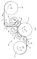
- a preferred apparatus 150 is shown schematically in FIG. 1 and FIG. 2 and discussed more fully below.
- the base substrate 20 according to the present invention is a fluid permeable fibrous nonwoven web formed from a loose collection of thermally stable fibers.
- the fibers according to the present invention are non extensible which was previously defined as elongating by less than 300% without rupture or breakage; however, the non extensible fibers forming the base substrate of the present invention preferably elongate by less than 200% without rupture or breakage.
- the fibers can include staple fibers formed into a web using industry standard carding, airlaid, or wetlaid technologies; however, continuous spunbond fibers forming spunlaid nonwoven webs using industry standard spunbond type technologies is preferred. Fibers and spunlaid processes for producing spunlaid webs are discussed more fully below.
- the fibers of the present invention may have various cross sectional shapes that include, but are not limited to; round, elliptical, star shaped, trilobal, multilobal with 3-8 lobes, rectangular, H-shaped, C-shaped, I-shape, U-shaped and other various eccentricities.
- Hollow fibers can also be used. Preferred shapes are round, trilobal and H-shaped. Round fibers are the least expensive and are therefore preferred from an econonic standpoint but trilobal shaped fibers provide increased surface area and are therefore preferred from a functional standpoint.
- the round and trilobal fiber shapes can also be hollow; however, solid fibers are preferred. Hollow fibers are useful because they have a higher compression resistance at equivalent denier than a solid fiber of the same shape and denier.
- Fibers in the present invention tend to be larger than those found in typical spunbond nonwovens. Because the diameter of shaped fibers can be hard to determine, the denier of the fiber is often referenced. Denier is defined as the mass of a fiber in grams at 9000 linear meters of length, expressed as dpf (denier per filament). For the present invention, the preferred denier range is greater than 1 dpf and less than 100 dpf. A more preferred denier range is 1.5 dpf to 50 dpf and a still more preferred range from 2.0 dpf to 20 dpf, and a most preferred range of 4 dpf to 10 dpf.
- the loose collection of fibers forming the base substrate of the present invention are bonded in advance of activation and corresponding fiber displacement.
- a fibrous web can be under bonded so that the fibers have a high level of mobility and tend to pull out from the bond sites under tension or fully bonded with much higher bond site integrity such that the fibers exhibit minimal fiber mobility and tend to break under tension.
- the non extensible fibers forming the base substrate of the present invention are preferably fully bonded to form a non extensible fibrous web material. As explained more fully below, a non extensible base substrate is preferred for forming the structured substrate via fiber displacement.
- Fully bonding of the base substrate can be done in one bonding step, e.g. during manufacturing of the base substrate.
- there can be more than one bonding step to make the pre-bonded base substrate e.g. the base substrate can be only lightly bonded or under bonded upon manufacturing to provide sufficient integrity to wind it up.
- the base substrate may then undergo further bonding steps to obtain a fully bonded web, e.g. immediately prior to subjecting the base substrate to the fiber displacement process of the present invention.
- Thru-air bonding is performed by passing a heated gas through a collection of fibers to produce a consolidated nonwoven web.
- Thermal point bonding involves applying heat and pressure to discrete locations to form bond sites on the nonwoven web.
- the actual bond sites include a variety of shapes and sizes; including but not limited to oval, round and four sided geometric shapes.
- the total overall thermal point bond area is between 2% and 60%, preferably between 4% and 35%, more preferably between 5% and 30% and most preferably between 8% and 20%.
- a fully bonded base substrate of the present invention has a total overall bond area of from 8% to 70%, preferably from 12% to 50%, and most preferably between 15% and 35%.
- the thermal point bonding pin density is between 5pins/cm 2 and 100pins/cm 2 , preferably between 10pins/cm 2 and 60pins/cm 2 and most preferably between 20pins/cm 2 and 40pins/cm 2 .
- a fully bonded base substrate of the present invention has a bonding pin density of from 10pins/cm 2 to 60 pins/cm 2 , preferably from 20 pins/cm 2 to 40 pins/cm 2 .
- Thermal bonding requires fibers formed from thermally bondable polymers, such as thermoplastic polymers and fiber made therefrom.
- the fiber composition includes a thermally bondable polymer.
- the preferred thermally bondable polymer comprises polyester resin, preferably PET resin, more preferably PET resin and coPET resin providing thermally bondable, thermally stable fibers as discussed more fully below.
- the thermoplastic polymer content is present at a level of greater than about 30%, preferably greater than about 50%, more preferably greater than about 70%, and most preferably greater than about 90% by weight of the fiber.
- the base substrate has mechanical properties in both the machine direction (MD) and cross machine direction (CD).
- the MD tensile strength is between 1 N/cm and 200 N/cm, preferably between 5 N/cm and 100 N/cm, more preferably between 10 N/cm and 50 N/cm and most preferably between 20 N/cm and 40 N/cm.
- the CD tensile strength is between 0.5 N/cm and 50 N/cm, preferably between 2 N/cm and 35 N/cm, and most preferably between 5 N/cm and 25 N/cm.
- the base substrate should also have a characteristic ratio of MD to CD tensile strength ratio between 1.1 and 10, preferably between 1.5 and 6 and most preferably between 1.8 and 5.
- the bonding method also influences the thickness of the base substrate.
- the base substrate thickness or caliper is also dependent on the number, size and shape of fiber present in a given measured location.
- the base substrate thickness is between 0.10 mm and 1.3 mm, more preferably between 0.15 mm and 1.0 mm and most preferably between 0.20 mm and 0.7 mm.
- the base substrate also has a characteristic opacity.
- Opacity is a measure of the relative amount of light that passes through the base substrate. Without wishing to be bound by theory, it is believed that the characteristic opacity depends on the number, size, type, morphology, and shape of fibers present in a given measured location. Opacity can be measured using TAPPI Test Method T 425 om-01 "Opacity of Paper (15/d geometry, Illuminant A/2 degrees, 89% Reflectance Backing and Paper Backing)". The opacity is measured as a percentage. For the present invention, the base substrate opacity is greater than 5%, preferably greater than 10%, more preferably greater than 20%, still more preferably greater than 30% and most preferably greater than 40%.
- the base substrate has a characteristic basis weight and a characteristic density.
- Basis weight is defined as a fiber/nonwoven mass per unit area.
- the basis weight of the base substrate is between 10 g/m 2 and 200 g/m 2 .
- the base substrate density is determined by dividing the base substrate basis weight by the base substrate thickness.
- the density of the base substrate is between 14 kg/m 3 and 200 kg/m 3 .
- the base substrate also has a base substrate specific volume which is an inverse of the base substrate density measured in cubic centimeters per gram.
- the base substrate of the present invention can be used to make roof felt, filtration articles, dryer sheets and other consumer products.
- the base substrate can be modified to optimize its fluid dispersion and acquisition properties for use in products where fluid management is important.
- the fluid dispersion properties can be enhanced by changing the surface energy of the base substrate to increase hydrophilicity and corresponding wicking properties. Modifying the surface energy of the base substrate is optional and is typically performed as the base substrate is made.
- the fluid acquisition properties can be influenced by modifying the structure of the base substrate by fiber displacement to introduce a 3D texture which increases the thickness or loft and corresponding specific volume of the substrate.
- Hydrophilicity of the base substrate relates to the surface energy.
- the surface energy of the base substrate can be modified through topical surface treatments, chemical grafting to the surface of the fibers or reactive oxidization of the fiber surfaces via plasma or corona treatments then further chemical bonding from gas reaction addition.
- the surface energy of the base substrate can also be influenced by the polymeric material used in producing the fibers of the base substrate.
- the polymeric material can either have inherent hydrophilicity or it can be rendered hydrophilic through chemical modification of the polymer, fiber surface, and base substrate surface through melt additives or combination of the polymeric material with other materials that induce hydrophilic behavior.
- materials used for polypropylene are IRGASURF ® HL560 from Ciba and a PET copolymer from Eastman Chemical, EASTONE ® family of polymeric materials for PET.
- Topical treatment of fiber surfaces generally involves surfactants that are added in an emulsion via foam, spray, kiss-roll or other suitable technique in a diluted state and then dried.
- Polymers that might require a topical treatment are polypropylene or polyester terephthalate based polymer systems.
- Other polymers include aliphatic polyesteramides; aliphatic polyesters; aromatic polyesters including polyethylene terephthalates and copolymers, polybutylene terephthalates and copolymers; polytrimethylene terephthalates and copolymers; polylactic acid and copolymers.
- a category of materials referred to as soil release polymers (SRP) are also suitable for topical treatment.
- Soil release polymers are a family of materials that include low molecular weight polyester polyether, polyester polyether block copolymer and nonionic polyester compounds. Some of these materials can be added as melt additives, but their preferred usage is as topical treatments. Commercial examples of this category of materials are available from Clariant as the TexcareTM family of products.
- the second modification to the base substrate 20 involves mechanically treating the base substrate to produce a structured fibrous web substrate (the terms “structured fibrous web” and “structured substrate” are used interchangeably herein).
- the structured substrate is defined as (1) a base substrate permanently deformed through fiber rearrangement and fiber separation and breakage producing permanent fiber dislocation (referred to hereinafter as “fiber displacement") such that the structured substrate has a thickness value which is higher than that of the base substrate and optionally (2) a base substrate modified by over bonding (referred to hereinafter as “over bonding”) to form a compressed region below the thickness of the base substrate.
- Fiber displacement processes involve permanent mechanical displacement of fibers via rods, pins, buttons, structured screens or belts or other suitable technology.
- the permanent fiber dislocation provides additional thickness or caliper compared to the base substrate.
- the additional thickness increases specific volume of the substrate and also increases fluid permeability of the substrate.
- the over bonding improves the mechanical properties of the base substrate and can enhance the depth of channels in between displaced fiber regions for fluid management.
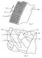
- the base substrate previously described can be processed using the apparatus 150 shown in FIG.1 to form structured substrate 21, a portion of which is shown in FIGS. 3-6 .
- the structured substrate has a first region 2 in the X-Y plane and a plurality of second regions 4 disposed throughout the fist region 2.
- the second regions 4 comprise displaced fibers 6 forming discontinuities 16 on the second surface 14 of the structured substrate 21 and displaced fibers 6 having loose ends 18 extending from the first surface 12.
- the displaced fibers 6 extend from a first side of the second region 4 and are separated and broken forming loose ends 18 along a second side 13 opposite the first side proximate to the first surface 12.
- proximate to the first surface 12 means the fiber breakage occurs between the first surface 12 and the peak or distal portion 3 of the displaced fibers, preferably, closer to the first surface 12 than to the distal portion 3 of the displaced fibers 6.
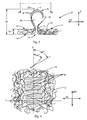
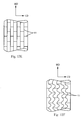
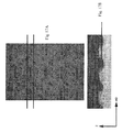
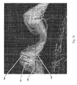
- a base substrate comprising fully bonded non extensible fibers provides a structure that due to its fiber strength, fiber stiffness, and bonding strength forms tent like structures at low fiber displacement deformations, as shown in the micrograph in FIG. 15 . Once the fiber displacement deformation is extended, substantial fiber breakage is observed, typically concentrated on one side as shown in the micrograph in FIG. 16 .
- the purpose for creating the displaced fibers 6 having loose ends 18 in FIG. 4 is to increase the structured substrate specific volume over the base substrate specific volume by creating void volume.
- creating displaced fibers 6 having at least 50% and less than 100% loose ends in the second regions produces a structured substrate having an increased caliper and corresponding specific volume which is sustainable during use. (See Table 6, examples 1N5 - 1N9 provided below)
- the loose ends 18 of the displaced fibers 6 can be thermally bonded for improved compression resistance and corresponding sustainability. Displaced fibers 6 having thermally bonded loose ends and a process for producing the same are discussed more fully below.
- the displaced fibers 6 in second regions 4 exhibit a thickness or caliper which is greater than the first region 2 thickness 32 which typically will be the same as the base substrate thickness.
- the size and shape of the second regions 4 having displaced fibers 6 may vary depending on the technology used.
- FIG. 5 shows a cross section of the structured substrate 21 illustrating displaced fibers 6 in a second region 4.
- Displaced fiber 6 thickness 34 describes the thickness or caliper of the second region 4 of the structured substrate 21 resulting from the displaced fibers 6. As shown, the displaced fiber thickness 34 is greater than the first region thickness 32.
- displaced fiber thickness 34 be at least 110% greater than the first region thickness 32, more preferably at least 125% greater, and most preferably at least 150% greater than the first region thickness 32.
- the aged caliper for displaced fiber thickness 34 is between 0.1 mm and 5 mm, preferably between 0.2 mm and 2 mm and most preferably between 0.5 mm and 1.5 mm.
- the number of second regions 4 having displaced fibers 6 per unit area of structured substrate 21 can vary as shown in FIG. 3 .
- the area density need not be uniform across the entire area of structured substrate 21, but second regions 4 can be limited to certain regions of structured substrate 21, such as in regions having predetermined shapes, such as lines, stripes, bands, circles, and the like.
- the total area occupied by the second regions 4 is less than 75%, preferably less than 50% and more preferably less than 25% of the total area, but is at least 10%.
- the size of the second regions and spacing between second regions 4 can vary.
- FIG. 3 and FIG. 4 show the length 36, width 38 and spacing 37 and 39 between second regions 4.
- the spacing 39 in the machine direction between the second regions 4 shown in FIG. 3 is preferably between 0.1 mm and 1000 mm, more preferably between 0.5 mm and 100 mm and most preferably between 1 mm and 10 mm.
- the side to side spacing 37 between the second regions 4 in the cross machine direction is between 0.2 mm and 16 mm, preferably between 0.4 mm and 10 mm, more preferably between 0.8 mm and 7 nm and most preferably between 1 mm and 5.2 mm.
- structured substrate 21 can be formed from a generally planar, two dimensional nonwoven base substrate 20 supplied from a supply roll 152.
- the base substrate 20 moves in the machine direction MD by apparatus 150 to a nip 116 formed by intermeshing rollers 104 and 102A which form displaced fibers 6 having loose ends 18.
- the structured substrate 21 having displaced fibers 6 optionally proceeds to nip 117 formed between roll 104 and bonding roll 156 which bonds the loose ends 18 of the displaced fibers 6.
- structured substrate 22 proceeds to optionally intermeshing rolls 102B and 104 which removes structured substrate 22 from roll 104 and optionally conveys it to nip 119 formed between roll 102B and bonding roll 158 where over bond regions are formed in structured substrate 23 which is eventually taken up on supply roll 160.
- FIG. 1 illustrates the sequence of process steps as described, for base substrates which are not yet fully bonded it is desirable to reverse the process so that bonded regions are formed in the base substrate prior to forming displaced fibers 6.
- the base substrate 20 would be supplied from a supply roll similar to the take up supply roll 160 shown in FIG.
- nip 119 formed between roll 102B and bonding roll 158 where the substrate is bonded prior to entering nip 118 formed between intermeshing rolls 102B and 104 where displaced fibers 6 having loose ends 18 are formed in the second regions 4.
- FIG. 1 shows base substrate 20 supplied from supply roll 152
- the base substrate 20 can be supplied from any other supply means, such as festooned webs, as is known in the art.
- base substrate 20 can be supplied directly from a web making apparatus, such as a nonwoven web-making production line.
- first surface 12 corresponds to first side of base substrate 20, as well as the first side of structured substrate 21.
- Second surface 14 corresponds to the second side of base substrate 20, as well as the second side of structured substrate 21.
- side is used herein in the common usage of the term to describe the two major surfaces of generally two-dimensional webs, such as nonwovens.
- Base substrate 20 is a nonwoven web comprising substantially randomly oriented fibers, that is, randomly oriented at least with respect to the MD and CD.
- substantially randomly oriented is meant random orientation that, due to processing conditions, may exhibit a higher amount of fibers oriented in the MD than the CD, or vice-versa.
- Base substrate 20 can be provided either directly from a web making process or indirectly from a supply roll 152, as shown in FIG. 1 .
- Base substrate 20 can be preheated by means known in the art, such as by heating over oil-heated or electrically heated rollers.
- roll 154 could be heated to pre-heat the base substrate 20 prior to the fiber displacement process.
- supply roll 152 rotates in the direction indicated by the arrow as base substrate 20 is moved in the machine direction over roller 154 and to the nip 116 of a first set of counter-rotating intermeshing rolls 102A and 104.
- Rolls 102A and 104 are the first set of intermeshing rollers of apparatus 150.
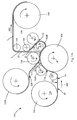
- the first set of intermeshing rolls 102A and 104 operate to form displaced fibers and to facilitate fiber breakage in base substrate 20, to make structured substrate referred to herein after as structured substrate 21. Intermeshing rolls 102A and 104 are more clearly shown in FIG. 2 .
- FIG. 2 there is shown in more detail the portion of apparatus 150 for making displaced fibers on structured substrate 21 of the present invention.
- This portion of apparatus 150 is shown as nip rollers 100 in FIG. 2 , and comprises a pair of intermeshing rolls 102 and 104 (corresponding to rolls 102A and 104, respectively, in FIG. 1 ), each rotating about an axis A , the axes A being parallel in the same plane.
- FIG. 2 shows in principle what happens as base substrate 20 goes through nip 116 on apparatus 150 and exits as structured substrate 21 having regions of displaced fibers 6.
- the intermeshing rolls can be made from metal or plastic.
- Non-limiting examples of metal rolls would be aluminum or steel.
- Non-limiting examples of plastic rolls would be polycarbonate, acrylonitrile butadiene styrene (ABS), and polyphenylene oxide (PPO).
- ABS acrylonitrile butadiene styrene
- PPO polyphenylene oxide
- the plastics can be filled with metals or inorganic additive materials.
- roll 102 comprises a plurality of ridges 106 and corresponding grooves 108 which can extend unbroken about the entire circumference of roll 102.
- roll 102 (and, likewise, roll 102A) can comprise ridges 106 wherein portions have been removed, such as by etching, milling or other machining processes, such that some or all of ridges 106 are not circumferentially continuous, but have breaks or gaps.
- the breaks or gaps can be arranged to form a pattern, including simple geometric patters such as circles or diamonds, but also including complex patterns such as logos and trademarks.
- roll 102 can have teeth, similar to the teeth on roll 104, described more fully below. In this manner, it is possible to have displaced fibers 6 on both sides 12,14 of structured substrate 21.
- Roll 104 is similar to roll 102, but rather than having ridges that can extend unbroken about the entire circumference, roll 104 comprises a plurality of rows of circumferentially-extending ridges that have been modified to be rows of circumferentially-spaced teeth 110 that extend in spaced relationship about at least a portion of roll 104.
- the individual rows of teeth 110 of roll 104 are separated by corresponding grooves 112.
- rolls 102 and 104 intermesh such that the ridges 106 of roll 102 extend into the grooves 112 of roll 104 and the teeth 110 of roll 104 extend into the grooves 108 of roll 102.
- the intermeshing is shown in greater detail in the cross sectional representation of FIG. 7 , discussed below.
- Both or either of rolls 102 and 104 can be heated by means known in the art such as by using hot oil filled rollers or electrically-heated rollers.
- structured substrate 21 has a first region 2 defined on both sides of structured substrate 21 by the generally planar, two-dimensional configuration of the base substrate 20, and a plurality of discrete second regions 4 defined by spaced-apart displaced fibers 6 and discontinuities 16 which can result from integral extensions of the fibers of the base substrate 20.
- the structure of second regions 4 is differentiated depending on which side of structured substrate 21 is considered.
- each discrete second region 4 can comprise a plurality of displaced fibers 6 extending outwardly from first surface 12 and having loose ends 18.
- Displaced fibers 6 comprise fibers having a significant orientation in the Z-direction, and each displaced fiber 6 has a base 5 disposed along a first side of the second region 4 proximal to the first surface 12, a loose end 18 separated or broken at a second side 13 of the second region 4 opposite the first side near the first surface 12 and a distal portion 3 at a maximum distance in the Z-direction from the first surface 12.
- second region 4 comprises discontinuities 16 which are defined by fiber orientation discontinuities 16 on the second surface 14 of structured substrate 21. The discontinuities 16 correspond to the locations where teeth 110 of roll 104 penetrated base substrate 20.
- the term "integral" as in "integral extension" when used of the second regions 4 refers to fibers of the second regions 4 having originated from the fibers of the base substrate 20. Therefore, the broken fibers 8 of displaced fibers 6, for example, can be plastically deformed and/or extended fibers from the base substrate 20, and can be, therefore, integral with first regions 2 of structured substrate 21. In other words, some, but not all of the fibers have been broken, and such fibers had been present in base substrate 20 from the beginning.
- integral is to be distinguished from fibers introduced to or added to a separate precursor web for the purpose of making displaced fibers. While some embodiments of structured substrates 21, 22 and 23 of the present invention may utilize such added fibers, in a preferred embodiment, broken fibers 8 of displaced fibers 6 are integral to structured substrate 21.
- a suitable base substrate 20 for a structured substrate 21 of the present invention having broken fibers 8 in displaced fibers 6 should comprise fibers having sufficient fiber immobility and/or plastic deformation to break and form loose ends 18. Such fibers are shown as loose fiber ends 18 in FIGS. 4 and 5 .
- loose fiber ends 18 of displaced fibers 6 are desirable for producing void space or free volume for collecting fluid. In a preferred embodiment at least 50%, more preferably at least 70% and less than 100% of the fibers urged in the Z-direction are broken fibers 8 having loose ends 18.
- the second regions 4 can be shaped to form patterns in both the X-Y plane and the Z-plane to target specific volume distributions that can vary in shape, size and distribution.
- Representative second region having displaced fibers 6 for the embodiment of structured substrate 21 shown in FIG. 2 is shown in a further enlarged view in FIGS. 3-6 .
- the representative displaced fibers 6 are of the type formed on an elongated tooth 110 on roll 104, such that the displaced fibers 6 comprises a plurality of broken fibers 8 that are substantially aligned such that the displaced fibers 6 have a distinct longitudinal orientation and a longitudinal axis L.
- Displaced fibers 6 also have a transverse axis T generally orthogonal to longitudinal axis L in the MD-CD plane. In the embodiment shown in FIGS. 2-6 , longitudinal axis L is parallel to the MD. In one embodiment, all the spaced apart second regions 4 have generally parallel longitudinal axes L.
- second regions 4 will have a longitudinal orientation, i.e. second regions will have an elongate shape and will not be circular.
- many of broken fibers 8 can have a substantially uniform alignment with respect to transverse axis T when viewed in plan view, such as in FIG. 6 .
- broken fibers 8 is meant that displaced fibers 6 begin on the first side 11 of second regions 4 and are separated along a second side 13 of second regions 4 opposite the first side 11 in structured substrate 21.
- displaced fibers 6 of structured substrate 21 are made by mechanically deforming base substrate 20 that can be described as generally planar and two dimensional.
- planar and two dimensional is meant simply that the web is flat relative to the finished structured substrate 1 that has distinct, out-of-plane, Z-direction three-dimensionality imparted due to the formation of second regions 4.
- Planar and two-dimensional are not meant to imply any particular flatness, smoothness or dimensionality.
- teeth 110 "push” or “punch” through base substrate 20.
- the portions of fibers that are oriented predominantly in the CD and across teeth 110 are urged by the teeth 110 out of the plane of base substrate 20 and are stretched, pulled, and/or plastically deformed in the Z-direction, resulting in formation of second region 4, including the broken fibers 8 of displaced fibers 6.
- Fibers that are predominantly oriented generally parallel to the longitudinal axis L, i.e., in the machine direction of base substrate 20 can be simply spread apart by teeth 110 and remain substantially in the first region 2 of base substrate 20.
- the apparatus 100 is shown in one configuration having one patterned roll, e.g., roll 104, and one non-patterned grooved roll 102.
- nip 116 it may be preferable to form nip 116 by use of two patterned rolls having either the same or differing patterns, in the same or different corresponding regions of the respective rolls.
- Such an apparatus can produce webs with displaced fibers 6 protruding from both sides of the structured web 21, as well as macro-patterns embossed into the web 21.
- the number, spacing, and size of displaced fibers 6 can be varied by changing the number, spacing, and size of teeth 110 and making corresponding dimensional changes as necessary to roll 104 and/or roll 102.
- This variation together with the variation possible in base substrate 20 and the variation in processing, such as line speeds, permits many varied structured webs 21 to be made for many purposes.
- the broken fibers 8 of displaced fibers 6 can originate and extend from either the first surface 12 or the second surface 14 of structured substrate 21.
- the broken fibers 8 of displaced fibers 6 can also extend from the interior 19 of structured substrate 21.
- the broken fibers 8 of displaced fibers 6 extend due to having been urged out of the generally two-dimensional plane of base substrate 20 (i.e., urged in the "Z -direction" as shown in FIG. 3 ).
- the broken fibers 8 or loose ends 18 of the second regions 4 comprise fibers that are integral with and extend from the fibers of the fibrous web first regions 2.
- the extension of broken fibers 8 can be accompanied by a general reduction in fiber cross sectional dimension (e.g., diameter for round fibers) due to plastic deformation of the fibers and the effects of Poisson's ratio. Therefore, portions of the broken fibers 8 of displaced fibers 6 can have an average fiber diameter less than the average fiber diameter of the fibers of base substrate 20 as well as the fibers of first regions 2. It has been found that the reduction in fiber cross-sectional dimension is greatest intermediate the base 5 and the loose ends 3 of displaced fibers 6. This is believed to be due to portions of fibers at the base 5 and distal portion 3 of displaced fibers 6 are adjacent the tip of teeth 110 of roll 104, described more fully below, such that they are frictionally locked and immobile during processing. In the present invention the fiber cross section reduction is minimal due to the high fiber strength and low fiber elongation.
- FIG. 7 shows in cross section a portion of the intermeshing rolls 102 (and 102A and 102B, discussed below) and 104 including ridges 106 and teeth 110.
- teeth 110 have a tooth height TH (note that TH can also be applied to ridge 106 height; in a preferred embodiment tooth height and ridge height are equal), and a tooth-to-tooth spacing (or ridge-to-ridge spacing) referred to as the pitch P.
- depth of engagement, (DOE) E is a measure of the level of intermeshing of rolls 102 and 104 and is measured from tip of ridge 106 to tip of tooth 110.
- the depth of engagement E, tooth height TH, and pitch P can be varied as desired depending on the properties of base substrate 20 and the desired characteristics of structured substrate 1 of the present invention. For example, in general, to obtain broken fibers 8 in displaced fibers 6 requires a level of engagement E sufficient to elongate and plastically deform the displaced fibers to a point where the fibers break. Also, the greater the density of second regions 4 desired (second regions 4 per unit area of structured substrate 1), the smaller the pitch should be, and the smaller the tooth length TL and tooth distance TD should be, as described below.
- FIG. 8 shows a portion of one embodiment of a roll 104 having a plurality of teeth 110 useful for making a structured substrate 21 or structured substrate 1 of spunbond nonwoven material from a spunbond nonwoven base substrate 20.
- An enlarged view of teeth 110 shown in FIG. 8 is shown in FIG. 9 .
- teeth 110 have a uniform circumferential length dimension TL of about 1.25 mm measured generally from the leading edge LE to the trailing edge TE at the tooth tip 111, and are uniformly spaced from one another circumferentially by a distance TD of about 1.5 mm.
- teeth 110 of roll 104 can have a length TL ranging from about 0.5 mm to about 3 mm and a spacing TD from about 0.5 mm to about 3 mm, a tooth height TH ranging from about 0.5 mm to about 10 mm, and a pitch P between about 1 mm (0.040 inches) and 2.54 mm (0.100 inches).
- Depth of engagement E can be from about 0.5 mm to about 5 mm (up to a maximum approaching the tooth height TH).
- E, P, TH, TD and TL can each be varied independently of each other to achieve a desired size, spacing, and area density of displaced fibers 6 (number of displaced fibers 6 per unit area of structured substrate 1).
- each tooth 110 has a tip 111, a leading edge LE and a trailing edge TE.
- the tooth tip 111 can be rounded to minimize fiber breakage and is preferably elongated and has a generally longitudinal orientation, corresponding to the longitudinal axes L of second regions 4. It is believed that to get the displaced fibers 6 of the structured substrate 1, the LE and TE should be very nearly orthogonal to the local peripheral surface 120 of roll 104. As well, the transition from the tip 111 and the LE or TE should be a relatively sharp angle, such as a right angle, having a sufficiently small radius of curvature such that, in use the teeth 110 push through base substrate 20 at the LE and TE.
- An alternative tooth tip 111 can be a flat surface to optimize bonding.
- structured substrate 21 may travel on rotating roll 104 to nip 117 between roll 104 and a first bonding roll 156.
- Bonding roll 156 can facilitate a number of bonding techniques.
- bonding roll 156 can be a heated steel roller for imparting thermal energy in nip 117, thereby melt-bonding adjacent fibers of structured web 21 at the distal ends (tips) of displaced fibers 6.
- bonding roll 156 is a heated roll designed to impart sufficient thermal energy to structured web 21 so as to thermally bond adjacent fibers of the distal ends of displaced fibers 6.
- Thermal bonding can be by melt-bonding adjacent fibers directly, or by melting an intermediate thermoplastic agent, such as polyethylene powder, which in turn, adheres adjacent fibers.
- Polyethylene powder can be added to base substrate 20 for such purposes.
- First bonding roll 156 can be heated sufficiently to melt or partially melt fibers at the distal ends 3 of displaced fibers 6.
- the amount of heat or heat capacity necessary in first bonding roll 156 depends on the melt properties of the fibers of displaced fibers 6 and the speed of rotation of roll 104.
- the amount of heat necessary in first bonding roll 156 also depends on the pressure induced between first bonding roll 156 and tips of teeth 110 on roll 104, as well as the degree of melting desired at distal ends 3 of displaced fibers 6.
- first bonding roll 156 is a heated steel cylindrical roll, heated to have a surface temperature sufficient to melt-bond adjacent fibers of displaced fibers 6.
- First bonding roll 156 can be heated by internal electrical resistance heaters, by hot oil, or by any other means known in the art for making heated rolls.
- First bonding roll 156 can be driven by suitable motors and linkages as known in the art.
- first bonding roll can be mounted on an adjustable support such that nip 117 can be accurately adjusted and set.
- FIG. 10 shows a portion of structured substrate 21 after being processed through nip 117 to be structured substrate 22, which, without further processing can be a structured substrate 21 of the present invention.
- Structured substrate 22 is similar to structured substrate 21 as described earlier, except that the distal ends 3 of displaced fibers 6 are bonded, and are preferably thermally melt-bonded such that adjacent fibers are at least partially bonded to form distally-disposed melt-bonded portions 9.
- the distal portions 3 of displaced fibers 6 can be heated to thermally join portions of fibers such that adjacent fiber portions are joined to one another to form displaced fibers 6 having melt-bonded portions 9, also referred to as "tip bonding".
- the distally-disposed melt-bonded portions 9 can be made by application of thermal energy and pressure to the distal portions of displaced fibers 6.
- the size and mass of the distally-disposed melt-bonded portions 9 can be modified by modifying the amount of heat energy imparted to the distal portions of displaced fibers 6, the line speed of apparatus 150, and the method of heat application.
- distally-disposed melt-bonded portions 9 can be made by application of radiant heat. That is, in one embodiment bonding roll 156 can be replaced or supplemented by a radiant heat source, such that radiant heat can be directed toward structured substrate 21 at a sufficient distance and corresponding sufficient time to cause fiber portions in the distally-disposed portions of displaced fibers 6 to soften or melt. Radiant heat can be applied by any of known radiant heaters. In one embodiment, radiant heat can be provided by a resistance-heated wire disposed in relation to structured substrate 21 such that it is extended in the CD direction at a sufficiently-close, uniformly-spaced distance that as the web is moved in relation to the wire, radiant heat energy at least partially melts the distally-disposed portions of displaced fibers 6. In another embodiment, a heated flat iron, such as a hand-held iron for ironing clothes, can be held adjacent the distal ends 3 of displaced fibers 6, such that melting is effected by the iron.
- the benefit of processing the structured substrate 22 as described above is that the distal ends 3 of displaced fibers 6 can be melted under a certain amount of pressure in nip 117 without compressing or flattening displaced fibers 6. As such, a three-dimensional web can be produced and set, or "locked in” to shape, so to speak by providing for thermal bonding after forming. Moreover, the distally-disposed bonded or melt-bonded portions 9 can aid in maintaining the lofty structure of displaced fibers 6 and aged caliper of the structured substrate when structured substrate 22 is subjected to compression or shearing forces.
- a structured substrate 22 processed as disclosed above to have displaced fibers 6 comprising fibers integral with but extending from first region 2 and having distally-disposed melt-bonded portions 9 can have improved shape retention after compression due to winding onto a supply roll and subsequently unwinding. It is believed that by bonding together adjacent fibers at distal portions of displaced fibers 6, the fibers experience less random collapse upon compression; that is, the entire structure of displaced fibers 6 tends to move together, thereby permitting better shape retention upon a disordering event such as compression and/or shear forces associated with rubbing the surface of the web. When used in a wiping or rubbing application, the bonded distal ends of displaced fibers 6 can also reduce fuzzing or pilling of structured substrate 1.
- substrate 20 is moved in the machine direction over roller 154 and to the nip 116 of the first set of counter-rotating intermeshing rolls 102A and 104 where the depth of engagement is between 0.01 inch and 0.15 inch such that partial fiber displacement occurs but there is little, if any, fiber breakage.
- the web then proceeds to nip 117 formed between roll 104 and bonding roll 156 where tips of the partial displaced fibers are bonded.
- the structured substrate 22 proceeds to nip 118 formed between roll 104 and 102B where the depth of engagement is greater than the depth of engagement at nip 116 such that the displaced fibers are further displaced forming broken fibers. This process can result in a larger number of the displaced fibers 6 being joined by the melt-bonded portions 9.
- Over bonding refers to melt bonding performed on a substrate that has been previously undergone fiber displacement. Over bonding is an optional process step. The over bonding can be done in-line, or can alternatively, be done on a separate converting process.
- the over bonding relies upon heat and pressure to fuse the filaments together in a coherent pattern.
- a coherent pattern is defined as a pattern that is reproducible along the length of the structured substrate so that a repeat pattern can be observed.
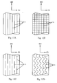
- the over bonding is done through a pressurized roller nip in which at least one of the rolls is heated, preferably both rolls are heated. If the over bonding is done when the base substrate is already heated, then the pressurized roller nip would not need to be heated. Examples of patterns of over bond regions 11 are shown in FIG.s 12a through 12f ; however, other over bond patterns are possible.
- FIG. 12a shows over bond regions 11 forming a continuous pattern in the machine direction.
- FIG. 12a shows over bond regions 11 forming a continuous pattern in the machine direction.
- FIG. 12b shows continuous over bond regions 11 in both the machine and cross-directions so that a continuous network of over bonds 11 is formed.
- This type of system can be produced with a single-step over bonding roll or multiple roll bonding systems.
- FIG. 12c shows over bond regions 11 that are discontinuous in the machine direction.
- the MD over bond pattern shown in FIG. 12c could also include over bond regions 11 in the CD connecting the MD over bond lines in a continuous or non-continuous design.
- FIG. 12d shows over bond regions 11 forming a wave pattern in the MD.
- FIG. 12e shows over bond regions 11 forming a herringbone pattern while FIG. 12f shows a wavy herringbone pattern.
- the over bond patterns do not need to be evenly distributed and can be contoured to suit a specific application.
- the total area affected by over bonding is less than 75% of the total area of the fibrous web, preferably less than 50%, more preferably less than 30% and most preferably less than 25%, but should be at least 3%.
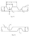
- FIG. 13 illustrates the characteristics of over bonding.
- the over bonded region 11 has a thickness property relative to the first region thickness 32 of the base substrate 20 measured in-between the over bonded regions.
- the over bonded region 11 has a compressed thickness 42.
- the over bonded region has a characteristic width 44 on the structured substrate 21 and a spacing 46 between over bond regions.
- the first region thickness 32 is preferably between 0.1 mm and 1.5 mm, more preferably between 0.15 mm and 1.3 mm, more preferably between 0.2 mm and 1.0 mm and most preferably between 0.25 mm and 0.7 mm.
- Over bonded region thickness 42 is preferably between 0.01 mm and 0.5 mm, more preferably between 0.02 mm and 0.25 mm, still more preferably between 0.03 mm and 0.1 mm and most preferably between 0.05 mm and 0.08 mm.
- the width 44 of the overbonded region 11 is between 0.05 mm and 15 mm, more preferably between 0.075 mm and 10 mm, still more preferably between 0.1 mm and 7.5 mm and most preferably between 0.2 mm and 5 mm.
- the spacing 46 between overbonded regions 11 is not required to be uniform in the structured substrate 21, but the extremes will fall within the range of 0.2 mm and 16 mm, preferably between 0.4 mm and 10 mm, more preferably between 0.8 mm and 7 mm and most preferably between 1 mm and 5.2 mm. Spacing 46, width 44 and thickness 42 of the over bonded regions 11 is based on the properties desired for the structured substrate 21 such as tensile strength and fluid handling properties.
- FIG. 13 shows that the over bonds 11 having over bond thickness 42 can be created on one side of the structured substrate 21.
- FIG. 14 shows that the over bonds 11 can be on either side of the structured substrate 21 depending on the method used to make the structured substrate 21.
- Over bonds 11 on both sides 12, 14 of the structured substrate 21 may be desired to create tunnels when the structured substrate is combined with other nonwovens to further aid in the management of fluids.
- a double sided structured substrate may be used in a multilayered high volume fluid acquisition system.
- structured substrate 23 can have bonded portions that are not, or not only, at distally-disposed portions of displaced fibers 6.
- bonded portions that are not, or not only, at distally-disposed portions of displaced fibers 6.
- a mating ridged roller instead of a flat, cylindrical roll for bonding roll 156
- other portions of the structured substrate 23 such as at locations on the first surface 12 in the first regions 2 between the second regions 4 can be bonded.
- continuous lines of melt-bonded material could be made on first surface 12 between rows of displaced fibers 6. The continuous lines of melt-bonded material form over bonded regions 11 as previously described.
- first bonding roll 156 there may be more than one bonding roll at this stage of the process, such that bonding takes place in a series of nips 117 and/or involving different types of bonding rolls 156.
- similar rolls can be provided to transfer various substances to base substrate 20 or structured web 21, such as various surface treatments to impart functional benefits. Any processes known in the art for such application of treatments can be utilized.
- structured substrate 22 After passing through nip 117, structured substrate 22 proceeds to nip 118 formed between roll 104. and 102B, with roll 102B preferably being identical to roll 102A.
- the purpose of going around roll 102B is to remove structured substrate 22 from roll 104 without disturbing the displaced fibers 6 formed thereon. Because roll 102B intermeshes with roll 104 just as roll 102A did, displaced fibers 6 can fit into the grooves 108 of roll 102B as structured substrate 22 is wrapped around roll 102B.
- structured substrate 22 After passing through nip 118, structured substrate 22 can be taken up on a supply roll for further processing as structured substrate 23 of the present invention. However, in the embodiment shown in FIG.
- structured substrate 22 is processed through nip 119 between roll 102B and second bonding roll 158.
- Second bonding roll 158 can be identical in design to first bonding roll 156. Second bonding roll 158 can provide sufficient heat to at least partially melt a portion of the second surface 14 of structured substrate 22 to form a plurality of non-intersecting, substantially continuous over bond regions 11 corresponding to the nip pressures between the tips of ridges 106 of roll 102B and the generally flat, smooth surface of roll 158.
- Second bonding roll 158 can be used as the only bonding step in the process (i.e., without first having structured substrate 22 formed by bonding the distal ends of displaced fibers 6).
- structured web 22 would be a structured web 23 with bonded portions on the second side 14 thereof.
- structured web 23 is preferably a double over bonded structured web 22 having bonded distal ends of displaced fibers 6 (tip bonding) and a plurality of non-intersecting, substantially continuous melt-bonded regions on first side 12 or second side 14 thereon.
- structured substrate 23 After structured substrate 23 is formed, it can be taken up on a supply roll 160 for storage and further processing as a component in other products.
- a second substrate 21A can be added to the structured substrate 21 using the process shown in FIG. 1A .
- the second substrate 21A can be a film, a nonwoven or a second base substrate as previously described.
- base substrate 20 is moved in the machine direction over roller 154 and to the nip 116 of the first set of counter-rotating intermeshing rolls 102A and 104 where the fibers are fully displaced forming broken fibers.
- the web then proceeds to nip 117 formed between roll 104 and bonding roll 156 where second substrate 21A is introduced and bonded to the distal portions 3 of the displaced fibers 6.
- the structured substrate 22 After passing through nip 117, the structured substrate 22 proceeds to nip 118 formed between rolls 104 and 102B where the depth of engagement is zero such that rolls 104 and 102B are not engaged, or the depth of engagement is less than the depth of engagement formed at nip 116 between rolls 102A and 104 such that the no additional fiber displacement occurs in the structured substrate.
- the depth of engagement at nip 118 can be set such that deformation occurs in the second substrate 21A but no additional fiber displacement occurs in the structured substrate 22. In other words, the depth of engagement at nip 118 is still less than the depth of engagement at nip 116.
- the composition used to form fibers for the base substrate of the present invention can include thermoplastic polymeric and non-thermoplastic polymeric materials.
- the thermoplastic polymeric material must have rheological characteristics suitable for melt spinning.
- the molecular weight of the polymer must be sufficient to enable entanglement between polymer molecules and yet low enough to be melt spinnable.
- thermoplastic polymers have molecular weights below about 1,000,000 g/mol, preferably from about 5,000 g/mol to about 750,000 g/mol, more preferably from about 10,000 g/mol to about 500,000 g/mol and even more preferably from about 50,000 g/mol to about 400,000 g/mol. Unless specified elsewhere, the molecular weight indicated is the number average molecular weight.
- thermoplastic polymeric materials are able to solidify relatively rapidly, preferably under extensional flow, and form a thermally stable fiber structure, as typically encountered in known processes such as a spin draw process for staple fibers or a spunbond continuous fiber process.
- Preferred polymeric materials include, but are not limited to, polypropylene and polypropylene copolymers, polyethylene and polyethylene copolymers, polyester and polyester copolymers, polyamide, polyimide, polylactic acid, polyhydroxyalkanoate, polyvinyl alcohol, ethylene vinyl alcohol, polyacrylates, and copolymers thereof and mixtures thereof.
- Other suitable polymeric materials include thermoplastic starch compositions as described in detail in U.S. publications 2003/0109605A1 and 2003/0091803 .
- polystyrene resins include ethylene acrylic acid, polyolefin carboxylic acid copolymers, and combinations thereof.
- Common thermoplastic polymer fiber grade materials are preferred, most notably polyester based resins, polypropylene based resins, polylactic acid based resin, polyhydroxyalkonoate based resin, and polyethylene based resin and combination thereof. Most preferred are polyester and polypropylene based resins.
- thermoplastic polymers suitable for use in the present invention include aliphatic polyesteramides; aliphatic polyesters; aromatic polyesters including polyethylene terephthalates (PET) and copolymer (coPET), polybutylene terephthalates and copolymers; polytrimethylene terephthalates and copolymers; polypropylene terephthalates and copolymers; polypropylene and propylene copolymers; polyethylene and polyethylene copolymers; aliphatic/aromatic copolyesters; polycaprolactones; poly(hydroxyalkanoates) including poly(hydroxybutyrate-co-hydroxyvalerate), poly(hydroxybutyrate-co-hexanoate), or other higher poly(hydroxybutyrate-co-alkanoates) as referenced in U.S.
- polyesters and polyurethanes derived from aliphatic polyols i.e., dialkanoyl polymers
- polyamides polyethylene/vinyl alcohol copolymers
- lactic acid polymers including lactic acid homopolymers and lactic acid copolymers
- lactide polymers including lactide homopolymers and lactide copolymers
- glycolide polymers including glycolide homopolymers and glycolide copolymers
- Suitable lactic acid and lactide polymers include those homopolymers and copolymers of lactic acid and/or lactide which have a weight average molecular weight generally ranging from about 10,000 g/mol to about 600,000 g/mol, preferably from about 30,000 g/mol to about 400,000 g/mol, more preferably from about 50,000 g/mol to about 200,000 g/mol.
- An example of commercially available polylactic acid polymers includes a variety of polylactic acids that are available from the Chronopol Incorporation located in Golden, Colorado, and the polylactides sold under the tradename EcoPLA®. Examples of suitable commercially available polylactic acid are NATUREWORKS from Cargill Dow and LACEA from Mitsui Chemical.
- Modified poly lactic acid and different stereo configurations may also be used, such as poly L-lactic acid and poly D,L-lactic acid with D-isomer levels up to 75%.
- Optional racenic combinations of D and L isomers to produce high melting temperature PLA polymers are also preferred.
- These high melting temperature PL polymers are special PLA copolymers (with the understanding that the D-isomer and L-isomer are treated as different stereo monomers) with melting temperatures above 180°C. These high melting temperatures are achieved by special control of the crystallite dimensions to increase the average melting temperature.
- more than one polymer may be desired.
- the polymers of the present invention are present in an amount to improve the mechanical properties of the fiber, the opacity of the fiber, optimize the fluid interaction with the fiber, improve the processability of the melt, and improve attenuation of the fiber.
- the selection and amount of the polymer will also determine if the fiber is thermally bondable and affect the softness and texture of the final product.
- the fibers of the present invention may comprise a single polymer, a blend of polymers, or be multicomponent fibers comprising more than one polymer.
- the fibers in the present invention are thermally bondable.
- Multiconstituent blends may be desired.
- blends of polyethylene and polypropylene referred to hereafter as polymer alloys
- polymer alloys Another example would be blends of polyesters with different viscosities or monomer content.
- Multicomponent fibers can also be produced that contain differentiable chemical species in each component. Non-limiting examples would include a mixture of 25 melt flow rate (MFR) polypropylene with 50MFR polypropylene and 25MFR homopolymer polypropylene with 25MFR copolymer of polypropylene with ethylene as a comonomer.
- MFR melt flow rate
- the more preferred polymeric materials have melting temperatures above 110°C, more preferably above 130°C, even more preferably above 145°C, still more preferably above 160°C and most preferably above 200°C.
- a still further preference for the present invention is polymers with high glass transition temperatures. Glass transition temperatures above -10°C in the end-use fiber form are preferred, more preferably above 0°C, still more preferably above 20°C and most preferably above 50°C. This combination of properties produces fibers that are stable at elevated temperatures.
- Exemplary examples of materials of this type are polypropylene, polylactic acid based polymers, and polyester terephthalate (PET) based polymer systems.
- the optional materials may be used to modify the processability and/or to modify physical properties such as opacity, elasticity, tensile strength, wet strength, and modulus of the final product.
- Other benefits include, but are not limited to, stability, including oxidative stability, brightness, color, flexibility, resiliency, workability, processing aids, viscosity modifiers, and odor control.
- optional materials include, but are not limited to, titanium dioxide, calcium carbonate, colored pigments, and combinations thereof.
- Further additives including, but not limited to, inorganic fillers such as the oxides of magnesium, aluminum, silicon, and titanium may be added as inexpensive fillers or processing aides.
- inorganic materials include, but are not limited to, hydrous magnesium silicate, titanium dioxide, calcium carbonate, clay, chalk, boron nitride, limestone, diatomaceous earth, mica glass quartz, and ceramics.
- inorganic salts including, but not limited to, alkali metal salts, alkaline earth metal salts and phosphate salts may be used.
- ingredients may be incorporated into the composition.
- These optional ingredients may be present in quantities of less than about 50%, preferably from about 0.1% to about 20%, and more preferably from about 0.1% to about 12% by weight of the composition.
- the optional materials may be used to modify the processability and/or to modify physical properties such as elasticity, tensile strength and modulus of the final product.
- Other benefits include, but are not limited to, stability including oxidative stability, brightness, flexibility, color, resiliency, workability, processing aids, viscosity modifiers, biodegradability, and odor control.
- Nonlimiting examples include salts, slip agents, crystallization accelerators or retarders, odor masking agents, cross-linking agents, emulsifiers, surfactants, cyclodextrins, lubricants, other processing aids, optical brighteners, antioxidants, flame retardants, dyes, pigments, fillers, proteins and their alkali salts, waxes, tackifying resins, extenders, and mixtures thereof.
- Slip agents may be used to help reduce the tackiness or coefficient of friction in the fiber. Also, slip agents may be used to improve fiber stability, particularly in high humidity or temperatures.
- a suitable slip agent is polyethylene.
- Thermoplastic starch (TPS) may also be added to the polymeric composition.
- polyester thermoplastic materials particularly PET.
- preferred materials are acetaldehyde acid scavengers, ethoxylated sorbitol esters, glycerol esters, alkyl sulphonate, combinations and mixtures thereof and derivative compounded.
- inorganic fillers such as the oxides of magnesium, aluminum, silicon, and titanium may be added as inexpensive fillers or processing aides.
- inorganic materials include hydrous magnesium silicate, titanium dioxide, calcium carbonate, clay, chalk, boron nitride, limestone, diatomaceous earth, mica glass quartz, and ceramics.
- inorganic salts including alkali metal salts, alkaline earth metal salts, phosphate salts, may be used as processing aides.
- Other optional materials that modify the water responsiveness of the thermoplastic starch blend fiber are stearate based salts, such as sodium, magnesium, calcium, and other stearates, as well as rosin component, such as gum rosin.
- Hydrophilic agents can be added to the polymeric composition.
- the hydrophilic agents can be added in standard methods known to those skilled in the art.
- the hydrophilic agents can be low molecular weight polymeric materials or compounds.
- the hydrophilic agent can also be a polymeric material with higher molecular weight.
- the hydrophilic agent can be present in an amount from 0.01 wt% to 90 wt%, with preferred range of 0.1 wt% to 50 wt% and a still more preferred range of 0.5 wt% to 10 wt%.
- the hydrophilic agent can be added when the initial resin is produced at the resin manufacturer, or added as masterbatch in the extruder when the fibers are made.
- Preferred agents are polyester polyether, polyester polyether copolymers and nonionic polyester compounds for polyester bases polymers. Ethoxylated low and high molecular weight polyolefinic compounds can also be added. Compatibilizing agents can be added to these materials to aid in better processing for these materials, and to make for a more uniform and homogenous polymeric compound.
- compatibilizing agents can be added in a compounding step to produce polymer alloys with melt additives not inherently effective with the base polymer.
- a base polypropylene resin can be combined with a hydrophilic polyester polyether copolymer through the use of maleated polypropylene as a compatibilizer agent.
- the fibers forming the base substrate in the present invention may be monocomponent or multicomponent.
- the term "fiber” is defined as a solidified polymer shape with a length to thickness ratio of greater than 1,000.
- the monocomponent fibers of the present invention may also be multiconstituent.
- Constituent as used herein, is defined as meaning the chemical species of matter or the material.
- Multiconstituent fiber as used herein, is defined to mean a fiber containing more than one chemical species or material. Multiconstituent and alloyed polymers have the same meaning in the present invention and can be used interchangeably.
- fibers may be of monocomponent or multicomponent types.
- Component as used herein, is defined as a separate part of the fiber that has a spatial relationship to another part of the fiber.
- the term multicomponent as used herein, is defined as a fiber having more than one separate part in spatial relationship to one another.
- the term multicomponent includes bicomponent, which is defined as a fiber having two separate parts in a spatial relationship to one another.
- the different components of multicomponent fibers are arranged in substantially distinct regions across the cross-section of the fiber and extend continuously along the length of the fiber. Methods for making multicomponent fibers are well known in the art. Multicomponent fiber extrusion was well known in the 1960's.
- DuPont was a lead technology developer of multicomponent capability, with US 3,244,785 and US 3,704,971 providing a technology description of the technology used to make these fibers.
- Bicomponent Fibers by R. Jeffries from Merrow Publishing in 1971 laid a solid groundwork for bicomponent technology. More recent publications include " Taylor-Made Polypropylene and Bicomponent Fibers for the Nonwoven Industry,” Tappi Journal December 1991 (p103 ) and “ Advanced Fiber Spinning Technology” edited by Nakajima from Woodhead Publishing .
- the nonwoven fabric formed in the present invention may contain multiple types of monocomponent fibers that are delivered from different extrusion systems through the same spinneret.
- the extrusion system in this example, is a multicomponent extrusion system that delivers different polymers to separate capillaries. For instance, one extrusion system would deliver polyester terephthalate and the other a polyester terephthalate copolymer such that the copolymer composition melts at a different temperatures. In a second example, one extrusion system might deliver a polyester terephthalate resin and the other polypropylene.
- one extrusion system might deliver a polyester terephthalate resin and the other an additional polyester terephthalate resin that has a molecular weight different from the first polyester terephthalate resin.
- the polymer ratios in this system can range from 95:5 to 5:95, preferably from 90:10 to 10:90 and 80:20 to 20:80.
- Bicomponent and multicomponent fibers may be in a side-by-side, sheath-core, segmented pie, ribbon, islands-in-the-sea configuration, or any combination thereof.
- the sheath may be continuous or non-continuous around the core.
- Non-inclusive examples of exemplarily multicomponent fibers are disclosed in US Patent 6,746,766 .
- the ratio of the weight of the sheath to the core is from about 5:95 to about 95:5.
- the fibers of the present invention may have different geometries that include, but are not limited to; round, elliptical, star shaped, trilobal, multilobal with 3-8lobes, rectangular, H-shaped, C-shaped, I-shape, U-shaped and other various eccentricities. Hollow fibers can also be used.
- Preferred shapes are round, trilobal and H-shaped.
- the round and trilobal fiber shapes can also be hollow.
- a "highly attenuated fiber” is defined as a fiber having a high draw down ratio.
- the total fiber draw down ratio is defined as the ratio of the fiber at its maximum diameter (which is typically results immediately after exiting the capillary) to the final fiber diameter in its end use.
- the total fiber draw down ratio will be greater than 1.5, preferable greater than 5, more preferably greater than 10, and most preferably greater than 12. This is necessary to achieve the tactile properties and useful mechanical properties.
- the fiber "diameter'' of the shaped fiber of the present invention is defined as the diameter of a circle which circumscribes the outer perimeter of the fiber.
- the diameter is not of the hollow region but of the outer edge of the solid region.
- fibers diameters are measured using a circle circumscribed around the outermost points of the lobes or edges of the non-round fiber. This circumscribed circle diameter may be referred to as that fiber's effective diameter.
- the highly attenuated multicomponent fiber will have an effective fiber diameter of less than 500 micrometers. More preferably the effective fiber diameter will be 250 micrometer or less, even more preferably 100 micrometers or less, and most preferably less than 50 micrometers.
- Fibers commonly used to make nonwovens will have an effective fiber diameter of from about 5 micrometers to about 30 micrometers. Fibers in the present invention tend to be larger than those found in typical spunbond nonwovens. As such fibers with effective diameters less than 10 micrometers are not of use. Fibers useful in the present invention have an effective diameter greater than about 10 microns, more preferably greater than 15 micrometers, and most preferably greater than 20 micrometer. Fiber diameter is controlled by spinning speed, mass through-put, and blend composition. When the fibers in the present invention are made into a discrete layer, that layer can be combined with additional layers that may contain small fibers, even nano-dimension fibers.
- spunlaid diameter refers to fibers having an effective diameter greater than about 12.5 micrometers up to 50 micrometers. This diameter range is produced by most standard spunlaid equipment. Micrometers and micron ( ⁇ m) mean the same thing and can be used interchangeably. Meltblown diameters are smaller than spunlaid diameters. Typically, meltblown diameters are from about 0.5 to about 12.5 micrometers. Preferable meltblown diameters range from about 1 to about 10 micrometers.
- the denier of the fiber is often referenced. Denier is defined as the mass of a fiber in grams at 9000 linear meters of length, expressed as dpf (denier per filament). Thus, the inherent density of the fiber is also factored in when converting from diameter to denier and visa versa.
- the preferred denier range is greater than 1 dpf and less than 100 dpf.
- a more preferred denier range is 1.5 dpf to 50 dpf and a still more preferred range from 2.0 dpf to 20 dpf, and a most preferred range of 4 dpf to 10 dpf.
- An example of the denier to diameter relationship for polypropylene is a 1 dpf fiber of polypropylene that is solid round with a density of about 0.900 g/cm 3 has a diameter of about 12.55 micrometers.
- the fibers of the present invention will have individual fiber breaking loads of greater than 5 grams per filament.
- Tensile properties of fibers are measured following a procedure generally described by ASTM standard D 3822-91 or an equivalent test, but the actual test that was used is fully described below.
- the tensile modulus (initial modulus as specified in ASTM standard D 3822-91 unless otherwise specified) should be greater than 0.5 GPa (giga pascals), more preferably greater than 1.5 GPa, still more preferably more than 2.0 GPa and most preferably greater than 3.0 GPa.
- the higher tensile modulus will produce stiffer fibers that provide a sustainable specific volume. Examples will be provided below.
- the hydrophilicity and hydrophobicity of the fibers can be adjusted in the present invention.
- the base resin properties can have hydrophilic properties via copolymerization (such as the case for certain polyesters (EASTONE from Eastman Chemical, the sulfopolyester family of polymers in general) or polyolefins such as polypropylene or polyethylene) or have materials added to the base resin to render it hydrophilic.
- Exemplarily examples of additives include CIBA Irgasurf ® family of additives.
- the fibers in the present invention can also be treated or coated after they are made to render them hydrophilic. In the present invention, durable hydrophilicity is preferred. Durable hydrophilicity is defined as maintaining hydrophilic characteristics after more than one fluid interaction.
- the sample being evaluated is tested for durable hydrophilicity
- water can be poured on the sample and wetting observed. If the sample wets out it is initially hydrophilic. The sample is then completely rinsed with water and dried. The rinsing is best done by putting the sample in a large container and agitating for ten seconds and then drying. The sample after drying should also wet out when contacted again with water.
- the fibers of the present invention are thermally stable. Fiber thermal stability is defined as having less than 30% shrinkage in boiling water, more preferably less than 20% shrinkage and most preferably less than 10% shrinkage. Some fibers in the present invention will have shrinkage less than 5%. The shrinkage is determined by measuring the fiber length before and after being placed in boiling water for one minute. Highly attenuated fibers would enable production of thermally stable fibers.
- the fiber shapes used in the base substrate in the present invention may consist of solid round, hollow round and various multi-lobal shaped fibers, among other shapes.
- a mixture of shaped fibers having cross-sectional shapes that are distinct from one another is defined to be at least two fibers having cross-sectional shapes that are different enough to be distinguished when examining a cross-sectional view with a scanning electron microscope.
- two fibers could be trilobal shape but one trilobal having long legs and the other trilobal having short legs.
- the shaped fibers could be distinct if one fiber is hollow and another solid even if the overall cross-sectional shape is the same.
- the multi-lobal shaped fibers may be solid or hollow.
- the multi-lobal fibers are defined as having more than one inflection point along the outer surface of the fiber.
- An inflection point is defined as being a change in the absolute value of the slope of a line drawn perpendicular to the surface of fiber when the fiber is cut perpendicular to the fiber axis.
- Shaped fibers also include crescent shaped, oval shaped, square shaped, diamond shaped, or other suitable shapes.
- Solid round fibers have been known to the synthetic fiber industry for many years. These fibers have a substantially optically continuous distribution of matter across the width of the fiber cross section. These fibers may contain micro voids or internal fibrillation but are recognized as being substantially continuous. There are no inflection points for the exterior surface of solid round fibers.
- the hollow fibers of the present invention will have a hollow region.
- a solid region of the hollow fiber surrounds the hollow region.
- the perimeter of the hollow region is also the inside perimeter of the solid region.
- the hollow region may be the same shape as the hollow fiber or the shape of the hollow region can be non-circular or non-concentric. There may be more than one hollow region in a fiber.
- the hollow region is defined as the part of the fiber that does not contain any material. It may also be described as the void area or empty space.
- the hollow region will comprise from about 2% to about 60% of the fiber. Preferably, the hollow region will comprise from about 5% to about 40% of the fiber. More preferably, the hollow region comprises from about 5% to about 30% of the fiber and most preferably from about 10% to about 30% of the fiber. The percentages are given for a cross sectional region of the hollow fiber (i.e. two dimensional).
- the percent of hollow region must be controlled for the present invention.
- the percent hollow region is preferably greater than 2% or the benefit of the hollow region is not significant. However, the hollow region is preferably less than 60% or the fiber may collapse.
- the desired percent hollow depends upon the materials used, the end use of the fiber, and other fiber characteristics and uses.
- the average fiber diameter of two or more shaped fibers having cross-sectional shapes that are distinct from on another is calculated by measuring each fiber type's average denier, converting the denier of each shaped fiber into the equivalent solid round fiber diameter, adding the average diameters together of each shaped fiber weighted by their percent total fiber content, and dividing by the total number of fiber types (different shaped fibers).
- the average fiber denier is also calculated by converting the average fiber diameter (or equivalent solid round fiber diameter) through the relationship of the fiber density.
- a fiber is considered having a different diameter if the average diameter is at least about 10% higher or lower.
- the two or more shaped fibers having cross-sectional shapes that are distinct from one another may have the same diameter or different diameters. Additionally, the shaped fibers may have the same denier or different denier. In some embodiments, the shaped fibers will have different diameters and the same denier.
- Multi-lobal fibers include, but are not limited to, the most commonly encountered versions such as trilobal and delta shaped.
- Other suitable shapes of multi-lobal fibers include triangular, square, star, or elliptical. These fibers are most accurately described as having at least one slope inflection point.
- a slope inflection point is defined as the point along the perimeter of the surface of a fiber where the slope of the fiber changes. For example, a delta shaped trilobal fiber would have three slope inflection points and a pronounced trilobal fiber would have six slope inflection points.
- Multilobal fibers in the present invention will generally have less than about 50 slope inflection points, and most preferably less than about 20 slope inflection points.
- the multi-lobal fibers can generally be described as non-circular, and may be either solid or hollow.
- the mono and multiconstituent fibers of the present invention may be in many different configurations. Constituent, as used herein, is defined as meaning the chemical species of matter or the material. Fibers may be of monocomponent in configuration. Component, as used herein, is defined as a separate part of the fiber that has a spatial relationship to another part of the fiber.
- the fiber may further be treated or the bonded fabric can be treated.
- a hydrophilic or hydrophobic finish can be added to adjust the surface energy and chemical nature of the fabric.
- fibers that are hydrophobic may be treated with wetting agents to facilitate absorption of aqueous liquids.
- a bonded fabric can also be treated with a topical solution containing surfactant, pigments, slip agents, salt, or other materials to further adjust the surface properties of the fiber.
- the fibers in the present invention can be crimped, although it is preferred that they are not crimped.
- Crimped fibers are generally produced in two methods. The first method is mechanical deformation of the fiber after it is already spun. Fibers are melt spun, drawn down to the final filament diameter and mechanically treated, generally through gears or a stuffer box that imparts either a two dimensional or three dimensional crimp. This method is used in producing most carded staple fibers; however, carded staple fiber fabrics are not preferred because the fibers are not continuous and the fabrics produced from crimped fibers are generally very lofty before the fiber deformation technology is used.
- the second method for crimping fibers is to extrude multicomponent fibers that are capable of crimping in a spunlaid process.
- bicomponent crimped spunbond fibers exists; however, for the present invention, three main techniques are considered for making crimped spunlaid nonwovens.
- the first is crimping that occurs in the spinline due to differential polymer crystallization in the spinline, a result of differences in polymer type, polymer molecular weight characteristics (e.g. molecular weight distribution) or additives content.
- a second method is differential shrinkage of the fibers after they have been spun into a spunlaid substrate. For instance, heating the spunlaid web can cause fibers to shrink due to differences in crystallinity in the as-spun fibers, for example during the thermal bonding process.
- a third method of causing crimping is to mechanically stretch the fibers or spunlaid web (generally for mechanical stretching the web has been bonded together).
- the mechanical stretching can expose differences in the stress-strain curve between the two polymer components, which can cause crimping.
- the base substrate contains less than 100wt% crimped fibers, preferably less than 50wt% crimped fibers, more preferably less than 20wt% crimped fibers, more preferably less than 10wt% and most preferably 0wt% crimped fibers.
- Uncrimped fibers are preferred because the crimping process can reduce the amount of fluids transferred on the surface of the fibers and also the crimping can reduce the inherent capillarity of the base substrate by decreasing the specific density of the base substrate.
- Short length fibers are defined as fibers having a length of less than 50mm.
- continuous fibers are preferred over short cut fibers as they provide two additional benefits.
- the first benefit is that fluids can be transferred greater distances without fiber ends, thus providing enhanced capillarity.
- the second benefit is that continuous fibers produce base substrates with higher tensile strengths and stiffness, because the bonded network has continuous matrix of fibers that collectively are more inter-connected than one composed of short length fibers. It is preferred that the base substrate of the present invention contain very few short length fibers, preferably less than 50wt% short length fibers, more preferably less than 20wt% short length fibers, more preferably less than 10wt% and most preferably 0wt% short length fibers.
- the fibers produced for the base substrate in the present invention are preferably thermally bondable.
- Thermally bondable in the present invention is defined as fibers that soften when they are raised near or above their peak melting temperature and that stick or fuse together under the influence of at least low applied pressures.
- the total fiber thermoplastic content should be more than 30 wt%, preferably more than 50 wt%, still more preferably more than 70 wt% and most preferably more than 90 wt%.
- the fibers forming the base substrate in the present invention are preferably continuous filaments forming spunlaid fabrics.
- Spunlaid fabrics are defined as unbonded fabrics having basically no cohesive tensile properties formed from essentially continuous filaments.
- Continuous filaments are defined as fibers with high length to diameter ratios, with a ratio of more than 10,000:1.
- Continuous filaments in the present invention that compose the spunlaid fabric are not staple fibers, short cut fibers or other intentionally made short length fibers.
- the continuous filaments in the present invention are on average, more than 100 mm long, preferably more than 200 mm long.
- the continuous filaments in the present invention are also not crimped, intentionally or unintentionally.
- the spunlaid processes in the present invention are made using a high speed spinning process as disclosed in US Patents Nos 3,802,817 ; 5,545,371 ; 6,548,431 and 5,885,909 .
- extruders supply molten polymer to melt pumps, which deliver specific volumes of molten polymer that transfer through a spinpack, composed of a multiplicity of capillaries formed into fibers, where the fibers are cooled through an air quenching zone and are pneumatically drawn down to reduce their size into highly attenuated fibers to increase fiber strength through molecular level fiber orientation.
- the drawn fibers are then deposited onto a porous belt, often referred to as a forming belt or forming table.
- the spunlaid process in the present invention used to make the continuous filaments will contain 100 to 10,000 capillaries per meter, preferably 200 to 7,000 capillaries per meter, more preferably 500 to 5,000 capillaries per meter, and still more preferably 1,000 to 3,000 capillaries per meter.
- the polymer mass flow rate per capillary in the present invention will be greater than 0.3GHM (grams per hole per minute).
- the preferred range is from 0.4GHM to 15GHM, preferably between 0.6GHM and 10GHM, still more preferred between 0.8GHM and 5GHM and the most preferred range from 1GHM to 4GHM.
- the spunlaid process in the present invention contains a single process step for making the highly attenuated, uncrimped continuous filaments. Extruded filaments are drawn through a zone of quench air where they are cooled and solidified as they are attenuated.
- Such spunlaid processes are disclosed in US 3338992 , US 3802817 , US 4233014 US 5688468 , US 6548431B1 , US 6908292B2 and US Application 2007/0057414A1 .
- the technology described in EP 1340843B1 and EP 1323852B1 can also be used to produce the spunlaid nonwovens.
- a preferred spunlaid process in the current invention includes a drawing device that pneumatically draws the fibers between the spinneret exits to the pneumatic drawing device enabling fibers to lay down onto the forming belt. The process differs from other spunlaid processes that mechanically draw the fibers from the spinneret.
- the spunlaid process for the present invention produces, in a single step; thermally stable, continuous, uncrimped fibers that have a defined inherent tensile strength, fiber diameter or denier as disclosed earlier.
- Preferred polymeric materials include, but are not limited to, polypropylene and polypropylene copolymers, polyethylene and polyethylene copolymers, polyester and polyester copolymers, polyamide, polyimide, polylactic acid, polyhydroxyalkanoate, polyvinyl alcohol, ethylene vinyl alcohol, polyacrylates, and copolymers thereof and mixtures thereof.
- Other suitable polymeric materials include thermoplastic starch compositions as described in detail in U.S. publications 2003/0109605A1 and 2003/0091803 .
- Still other suitable polymeric materials include ethylene acrylic acid, polyolefin carboxylic acid copolymers, and combinations thereof.
- Common thermoplastic polymer fiber grade materials are preferred, most notably polyester based resins, polypropylene based resins, polylactic acid based resin, polyhydroxyalkonoate based resin, and polyethylene based resin and combination thereof. Most preferred are polyester and polypropylene based resins.
- a suitable copolyester is Eastman 9921 (IV-0.81).
- the polyester intrinsic viscosity (IV) range suitable for the present invention ranges from 0.3 dl/g to 0.9 dl/g, preferably from 0.45 dl/g to 0.85 dl/g and more preferably from 0.55 dl/g to 0.82 dl/g.
- Polyester fibers in the present invention may be alloys, monocomponent and shaped.
- a preferred embodiment is polyester fibers that are multilobal, preferably trilobal, that are produced from a 0.61 dl/g resin with a denier between 3 dpf and 8 dpf.
- PET is most commonly referenced in this invention, other polyester terephthalate polymers can be used, such as PBT, PTT, PCT.
- the Thermal stability is achieved through a spinning speed greater than 4000 meter/minute and producing filament deniers ranging from 1dpf to 10 dpf in both round and shaped fibers.
- Basis weights ranging from 5 g/m 2 to 100 g/m 2 have been produced. These fabrics have been produced with thermal point bonding. These types of fabrics can be used in a wide range of applications, such as disposable absorbent articles, dryer sheets, and roof felting.
- a multibeam system can be used alone or can have a fine fiber diameter layer placed in between two spunlaid layers and then bonded together.
- An additional preferred embodiment is the use of polypropylene fibers and spunlaid nonwovens.
- the preferred resin properties for polypropylene are melt flow rates between 5 MFR (melt flow rate in grams per 10 minutes) and 400 MFR, with a preferred range between 10 MFR and 100 MFR and a still more preferred range between 15 MFR and 65 MFR with the most preferred range between 23 MFR and 40 MFR.
- the method used to measure MFR is outlined in ASTM D1238 measured at 230°C with a mass of 2.16 kg.
- the nonwoven products produced from the monocomponent and multicomponent fibers will also exhibit certain properties, particularly, strength, flexibility, softness, and absorbency. Measures of strength include dry and/or wet tensile strength. Flexibility is related to stiffness and can attribute to softness. Softness is generally described as a physiologically perceived attribute which is related to both flexibility and texture. Absorbency relates to the products' ability to take up fluids as well as the capacity to retain them. Absorbency in the present invention does not involve the internal regions of the fiber itself up taking water, such as is found with pulp fibers, regenerated cellulose fibers (e.g. rayon). Because some thermoplastic polymers inherently take-up small amount of water (e.g.
- the water uptake is limited to less than 10 wt%, preferably less than 5 wt% and most preferably less than 1 wt%.
- the absorbency in the present invention arises from the hydrophilicity of the fibers and nonwoven structure and depends primarily on the fiber surface area, pore size, and bonding intersections.
- Capillarity is the general phenomenon used to describe the fluid interaction with the fibrous substrate. The nature of capillarity is well understood to those skilled in the art and is presented in detail in "Nonwovens: Theory, Process, Performance and Testing" by Albin Turbak, Chapter 4.
- the spunlaid web forming the base substrate in the present invention will have an absorbency uptake or holding capacity (C holding ) between 1g/g (gram per gram) to 10g/g, more preferably between 2g/g and 8g/g and most preferably between 3g/g and 7g/g.
- C holding absorbency uptake or holding capacity
- This uptake measurement is done by weighing a dry sample (in grams) that is 15 cm long in MD and 5cm wide in CD, dry weight is m dry then submerging the sample in distilled water for 30 seconds and then removing the sample from water, suspending it vertically (in MD) for 10 seconds and then weighing the sample again, wet weight is m wet .
- the structured substrates have similar holding capacity.
- the spunlaid process in the current invention will produce a spunlaid nonwoven with a desired basis weight.
- Basis weight is defined as a fiber/nonwoven mass per unit area.
- the basis weight of the base substrate is between 10 g/m 2 and 200 g/m 2 , with a preferred range between 15 g/m 2 and 100 g/m 2 , with a more preferred range between 18 g/m 2 and 80 g/m 2 and even a more preferred range between 25 g/m 2 and 72 g/m 2 .
- the most preferred range is between 30 g/m 2 and 62 g/m 2 .
- the first step in producing a multiconstituent fiber is the compounding or mixing step.
- the raw materials are heated, typically under shear.
- the shearing in the presence of heat will result in a homogeneous melt with proper selection of the composition.
- the melt is then placed in an extruder where fibers are formed.
- a collection of fibers is combined together using heat, pressure, chemical binder, mechanical entanglement, and combinations thereof resulting in the formation of a nonwoven web.
- the nonwoven is then modified and assembled into a base substrate.
- the objective of the compounding step is to produce a homogeneous melt composition.
- the purpose of this step is to melt blend the thermoplastic polymers materials together where the mixing temperature is above the highest melting temperature thermoplastic component.
- the optional ingredients can also be added and mixed together.
- the melt composition is homogeneous, meaning that a uniform distribution is found over a large scale and that no distinct regions are observed.
- Compatibilizing agents can be added to combine materials with poor miscibility, such as when polylactic acid is added to polypropylene or thermoplastic starch is added to polypropylene.
- Twin-screw compounding is well known in the art and is used to prepare polymer alloys or to properly mix together polymers with optional materials.
- Twin-screw extruders are generally a stand alone process used between the polymer manufacture and the fiber spinning step. In order to reduce cost, the fiber extrusion can begin with twin-screw extruder such that the compounding is directly coupled with fiber making. In certain types of single screw extruders, good mixing and compatibilization can occur in-line.
- the most preferred mixing device is a multiple mixing zone twin screw extruder with multiple injection points.
- a twin screw batch mixer or a single screw extrusion system can also be used. As long as sufficient mixing and heating occurs, the particular equipment used is not critical.
- the present invention utilizes the process of melt spinning.
- melt spinning there is no mass loss in the extrudate.
- Melt spinning is differentiated from other spinning, such as wet or dry spinning from solution, where a solvent is being eliminated by volatilizing or diffusing out of the extrudate resulting in a mass loss.
- Spinning will occur at 120°C to about 350°C, preferably 160° to about 320°, most preferably from 190°C to about 300°.
- Fiber spinning speeds of greater than 100 meters/minute are required.
- the fiber spinning speed is from about 1,000 to about 10,000 meters/minute, more preferably from about 2,000 to about 7,000, and most preferably from about 2,500 to about 5,000 meters/minute.
- the polymer composition must be spun fast to make strong and thermally stable fibers, as determined by single fiber testing and thermal stability of the base substrate or structured substrate.
- the homogeneous melt composition can be melt spun into monocomponent or multicomponent fibers on commercially available melt spinning equipment.
- the equipment will be chosen based on the desired configuration of the multicomponent fiber.
- Commercially available melt spinning equipment is available from Hills, Inc, located in Melbourne, Florida.
- An outstanding resource for fiber spinning (monocomponent and multicomponent) is " Advanced Fiber Spinning Technology" by Nakajima from Woodhead Publishing .
- the temperature for spinning range from about 120° C to about 350° C.
- the processing temperature is determined by the chemical nature, molecular weights and concentration of each component. Examples of air attenuation technology are sold commercially by Hill's Inc, Neumag and REICOFIL.
- An example of technology suitable for the present invention is the Reifen ReifenNeill REICOFIL 4 spunlaid process. These technologies are well known in the nonwoven industry.
- the structured substrate of the present invention can be used to manage fluids. Fluid management is defined as the intentional movement of fluid through control of the structured substrate properties.
- fluid management is achieved through two steps. The first step is engineering the base substrate properties through fiber shape, fiber denier, basis weight, bonding method, and surface energy. The second step involves engineering the void volume generated through fiber displacement.
- Example 1 Spunbond fabrics were produced composed of 90 wt% Eastman F61HC PET resin and 10wt% Eastman 9921 coPET. The spunbond fabrics were produced using a pronounced trilobal spinneret that had 1.125 mm length and 0.15 mm width with a round end point. The hydraulic length-to-diameter ratio was 2.2:1. The spinpack had 250 capillaries of which 25 extruded the coPET resin and 225 extruded the PET resin. The beam temperature used was 285°C. The spinning distance was 33 inches and the forming distance was 34 inches. Different distances could be used in this and subsequent examples, but distance indicated provided the best results. The remainder of the relevant process data is included in Table 1-3.
- Comparative Example 1 Spunbond fabrics were produced composed of 90 wt% Eastman F61HC PET resin and 10 wt% Eastman 20110. The spunbond fabrics were produced using a pronounced trilobal spinneret that had 1.125 mm length and 0.15 mm width with a round end point. The hydraulic length-to-diameter ratio was 2.2:1. The spinpack had 250 capillaries of which 25 extruded the coPET resin and 225 extruded the PET resin. The beam temperature used was 285°C. The spinning distance was 33 inches and the forming distance was 34 inches. It was difficult to produce thermally stable spunbond nonwovens with this polymer combination. The coPET fibers were not thermally stable and caused the entire fiber structure to shrink when heated above 100°C. The MD fabric shrinkage was 20%.
- Example 2 Spunbond fabrics were produced composed of 100 wt% Eastman F61HC PET. The spunbond fabrics were produced using a pronounced trilobal spinneret that had 1.125 mm length and 0.15 mm width with a round end point. The hydraulic length-to-diameter ratio was 2.2:1. The spinpack had 250 capillaries. The beam temperature used was 285°C. The spinning distance was 33 inches and the forming distance was 34 inches. The remainder of the relevant process data is included in Table 1-3.
- Example 3 Spunbond fabrics were produced composed of 90 wt% Eastman F61HC PET resin and 10 wt% Eastman 9921 coPET.
- the spunbond fabrics were produced using a standard trilobal spinneret that had 0.55 mm length and 0.127 mm width with a round end point with radius 0.18 mm.
- the hydraulic length-to-diameter ratio was 2.2:1.
- the spinpack had 250 capillaries of which 25 extruded the coPET resin and 225 extruded the PET resin.
- the beam temperature used was 285°C.
- the spinning distance was 33 inches and the forming distance was 34 inches.
- the remainder of the relevant process data is included in Table 4-6.
- Example 4 Spunbond fabrics were produced composed of 90 wt% Eastman F61HC PET resin and 10 wt% Eastman 9921 coPET.
- the spunbond fabrics were produced using a solid round spinneret with capillary exit diameter of 0.35 mm and length-to-diameter ratio 4:1.
- the spinpack had 250 capillaries of which 25 extruded the coPET resin and 225 extruded the PET resin.
- the beam temperature used was 285°C.
- the spinning distance was 33 inches and the forming distance was 34 inches. The remainder of the relevant process data is included in Table 7-9.
- Comparative Example 3 Spunbond fabrics were produced composed of 90 wt% Eastman F61HC PET resin and 10 wt% Eastman 20110.
- the spunbond fabrics were produced using a solid round spinneret with capillary exit diameter of 0.35 mm and length-to-diameter ratio 4:1.
- the spinpack had 250 capillaries of which 25 extruded the coPET resin and 225 extruded the PET resin.
- the beam temperature used was 285°C.
- the spinning distance was 33 inches and the forming distance was 34 inches. It was difficult to produce thermally stable spunbond nonwovens with this polymer combination.
- the coPET fibers were not thermally stable and caused the entire fiber structure to shrink when heated above 100°C.
- the MD fabric shrinkage was 20%.
- samples in any of the methods being disclosed have been previously aged or has been removed from a product, they should be stored at 23 ⁇ 2°C and at 50 ⁇ 2% relative humidity for 24 hours with no compression, prior to any of the testing protocols.
- the samples after this aging would be referred to as "as-produced”.
- test methods for properties in the property tables are listed below. Unless specified otherwise, all tests are carried out at about 23 ⁇ 2°C and at 50 ⁇ 2% relative humidity. Unless specified explicitly, the specific synthetic urine used is made with 0.9% (by weight) saline (NaCL) solution made with deinonized water.
- NaCL saline
- the IPRP sample holder 400 is shown in FIG. 20 and comprises a cylindrical bottom plate 405, top plate 420, and cylindrical stainless steel weight 415 shown in detail in FIGs. 21A-C.
- Top plate 420 is 10 mm thick with an outer diameter of 70.0 mm and connected to a tube 425 of 190 mm length fixed at the center thereof.
- the tube 425 has in outer diameter of 15.8 mm and an inner diameter of 12.0 mm.
- the tube is adhesively fixed into a circular 12 mm hole in the center of the top plate 420 such that the lower edge of the tube is flush with the lower surface of the top plate, as depicted in FIG. 21A .
- the bottom plate 405 and top plate 420 are fabricated from Lexan® or equivalent.
- the stainless steel weight 415 shown in FIG. 21B has an outer diameter of 70 mm and an inner diameter of 15.9 mm so that the weight is a close sliding fit on tube 425.
- the thickness of the stainless steel weight 415 is approximately 25 mm and is adjusted so that the total weight of the top plate 420, the tube 425 and the stainless steel weight 415 is 788 g to provide 2.1 kPa of confining pressure during the measurement.
- bottom plate 405 is approximately 50 mm thick and has two registration grooves 430 cut into the lower surface of the plate such that each groove spans the diameter of the bottom plate and the grooves are perpendicular to each other. Each groove is 1.5 mm wide and 2 mm deep.
- Bottom plate 405 has a horizontal hole 435 which spans the diameter of the plate. The horizontal hole 435 has a diameter of 11 mm and its central axis is 12 mm below the upper surface of bottom plate 405.
- Bottom plate 405 also has a central vertical hole 440 which has a diameter of 10 mm and is 8 mm deep. The central hole 440 connects to the horizontal hole 435 to form a T-shaped cavity in the bottom plate 405. As shown in FIG.
- the outer portions of the horizontal hole 435 are threaded to accommodate pipe elbows 445 which are attached to the bottom plate 405 in a watertight fashion.
- One elbow is connected to a vertical transparent tube 460 with a height of 190 mm and an internal diameter of 10 mm.
- the tube 460 is scribed with a suitable mark 470 at a height of 50 mm above the upper surface of the bottom plate 420. This is the reference for the fluid level to be maintained during the measurement.
- the other elbow 445 is connected to the fluid delivery reservoir 700 (described below) via a flexible tube.
- a suitable fluid delivery reservoir 700 is shown in FIG. 22 .
- Reservoir 700 is situated on a suitable laboratory jack 705 and has an air-tight stoppered opening 710 to facilitate filling of the reservoir with fluid.
- An open-ended glass tube 715 having an inner diameter of 10 mm extends through a port 720 in the top of the reservoir such that there is an airtight seal between the outside of the tube and the reservoir.
- Reservoir 700 is provided with an L-shaped delivery tube 725 having an inlet 730 that is below the surface of the fluid in the reservoir, a stopcock 735, and an outlet 740.
- the outlet 740 is connected to elbow 445 via flexible plastic tubing 450 (e.g. Tygon®).
- the internal diameter of the delivery tube 725, stopcock 735, and flexible plastic tubing 450 enable fluid delivery to the IPRP sample holder 400 at a high enough flow rate to maintain the level of fluid in tube 460 at the scribed mark 470 at all times during the measurement.
- the reservoir 700 has a capacity of approximately 6 litres, although larger reservoirs may be required depending on the sample thickness and permeability.
- Other fluid delivery systems may be employed provided that they are able to deliver the fluid to the sample holder 400 and maintain the level of fluid in tube 460 at the scribed mark 470 for the duration of the measurement.
- the IPRP catchment funnel 500 is shown in FIG. 20 and comprises an outer housing 505 with an internal diameter at the upper edge of the funnel of approximately 125 mm. Funnel 500 is constructed such that liquid falling into the funnel drains rapidly and freely from spout 515. A horizontal flange 520 around the funnel 500 facilitates mounting the funnel in a horizontal position. Two integral vertical internal ribs 510 span the internal diameter of the funnel and are perpendicular to each other. Each rib 510 s 1.5 mm wide and the top surfaces of the ribs lie in a horizontal plane.
- the funnel housing 500 and ribs 510 are fabricated from a suitably rigid material such as Lexan® or equivalent in order to support sample holder 400.
- a bridge 530 is attached to flange 520 in order to mount a dial gauge 535 to measure the relative height of the stainless steel weight 415.
- the dial gauge 535 has a resolution of ⁇ 0.01 mm over a range of 25 mm.
- a suitable digital dial gauge is a Mitutoyo model 575-123 (available from McMaster Carr Co., catalog no. 19975-A73), or equivalent.
- Bridge 530 has two circular holes 17 mm in diameter to accommodate tubes 425 and 460 without the tubes touching the bridge.
- Funnel 500 is mounted over an electronic balance 600, as shown in Fig. 20 .
- the balance has a resolution of ⁇ 0.01 g and a capacity of at least 2000g.
- the balance 600 is also interfaced with a computer to allow the balance reading to be recorded periodically and stored electronically on the computer.
- a suitable balance is Mettler-Toledo model PG5002-S or equivalent.
- a collection container 610 is situated on the balance pan so that liquid draining from the funnel spout 515 falls directly into the container 610.
- the funnel 500 is mounted so that the upper surfaces of ribs 510 lie in a horizontal plane.
- Balance 600 and container 610 are positioned under the funnel 500 so that liquid draining from the funnel spout 515 falls directly into the container 610.
- the IPRP sample holder 400 is situated centrally in the funnel 700 with the ribs 510 located in grooves 430.
- the upper surface of the bottom plate 405 must be perfectly flat and level.
- the top plate 420 is aligned with and rests on the bottom plate 405.
- the stainless steel weight 415 surrounds the tube 425 and rests on the top plate 420.
- Tube 425 extends vertically through the central hole in the bridge 530.
- the dial gauge 535 is mounted finnly to the bridge 530 with the probe resting on a point on the upper surface of the stainless steel weight 415.
- the dial gauge is set to zero in this state.
- the reservoir 700 is filled with 0.9% saline solution and re-sealed.
- the outlet 740 is connected to elbow 445 via flexible plastic tubing 450.
- a an annular sample 475 of the material to be tested is cut by suitable means.
- the sample has an outer diameter of 70 mm and an inner hole diameter of 12 mm.
- One suitable means of cutting the sample is to use a die cutter with sharp concentric blades.
- the top plate 420 is lifted enough to insert the sample 475 between the top plate and the bottom plate 405 with the sample centered on the bottom plate and the plates aligned.
- the stopcock 735 is opened and the level of fluid in tube 460 is set to the scribed mark 470 by adjusting the height of the reservoir 700 using the jack 705 and by adjusting the position of the tube 715 in the reservoir.
- the reading on the dial gauge 535 is noted (initial sample thickness) and the recording of data from the balance by the computer is initiated. Balance readings and time elapsed are recorded every 10 seconds for five minutes. After three minutes the reading on the dial gauge is noted (final sample thickness) and the stopcock is closed.
- the average sample thickness L p is the average of the initial sample thickness and the final sample thickness expressed in cm.
- the flow rate in grams per second is calculated by a linear least squares regression fit to the data between 30 seconds and 300 seconds.
- the base substrate and the structured substrate of the present invention may be used for a wide variety of applications, including various filter sheets such as air filter, bag filter, liquid filter, vacuum filter, water drain filter, and bacterial shielding filter; sheets for various electric appliances such as capacitor separator paper, and floppy disk packaging material; various industrial sheets such as tacky adhesive tape base cloth, and oil absorbing material; various dry or premoistened wipes such as hard surface cleaning, floor care, and other home care uses, various wiper sheets such as wipers for homes, services and medical treatment, printing roll wiper, wiper for cleaning copying machine, baby wipers, and wiper for optical systems; various medicinal and sanitary sheets, such as surgical gown, medical gowns, wound care, covering cloth, cap, mask, sheet, towel, gauze, base cloth for cataplasm.
- Other applications include disposable absorbent articles as a means for managing fluids.
- Disposable absorbent article applications include tampon liners and diaper acquisition layers.
Claims (15)
- Nappe fibreuse structurée (22) comprenant des fibres thermoplastiques ayant un module d'au moins 0,5 GPa formant une nappe fibreuse stable thermiquement ; la nappe fibreuse comprenant une première surface (12) et une seconde surface (14), une première région (2) et une pluralité de secondes régions (4) distinctes disposées sur l'ensemble de la première région (2), les secondes régions (4) formant des discontinuités (16) sur la seconde surface (14) et des fibres déplacées (6) sur la première surface (12) ; dans laquelle au moins 50 % et moins de 100 % desdites fibres déplacées (6) dans chaque seconde région (4) sont fixées le long d'un premier côté de la seconde région (4) et séparées à proximité de la première surface le long d'un second côté (13) de la seconde région (4) face au premier côté, en formant des extrémités libres (18) s'étendant à l'opposé de la première surface (12) ; et dans laquelle les fibres déplacées (6) formant des extrémités libres (18) créent un volume de vide pour recueillir du fluide.
- Nappe fibreuse structurée (22) selon la revendication 1 comprenant en outre une pluralité de régions liées par en-dessus (11) disposées sur l'ensemble de la première région (2), dans laquelle chacune des régions liées par en-dessus (11), la première région (2) et les secondes régions (4) ont une épaisseur après vieillissement, l'épaisseur après vieillissement des secondes régions (4) formées par les extrémités libres (18) des fibres déplacées (6) étant inférieure à 1,5 mm, ce qui est supérieur à l'épaisseur après vieillissement de la première région (2), et l'épaisseur après vieillissement de la première région (2) étant supérieur à l'épaisseur après vieillissement des régions liées par en-dessus (11).
- Nappe fibreuse structurée (22) selon la revendication 1, dans laquelle la nappe fibreuse stable thermiquement autorise une contraction de moins de 30 %.
- Nappe fibreuse structurée (22) selon la revendication 1, dans laquelle les fibres sont des fibres filées-liées non ondulées continues.
- Nappe fibreuse structurée (22) selon la revendication 1, dans laquelle la nappe fibreuse est liée par points.
- Nappe fibreuse structurée (22) selon la revendication 2, dans laquelle les régions liées par en-dessus (11) sont continues.
- Nappe fibreuse structurée (22) selon la revendication 2, dans laquelle les régions liées par en-dessus (11) couvrent moins de 75 % de l'aire surfacique totale de la première surface (12) ou de la seconde surface (14) de la nappe fibreuse.
- Nappe fibreuse structurée (22) selon la revendication 1, dans laquelle les extrémités libres (18) des fibres déplacées (6) sont liées ensemble thermiquement.
- Nappe fibreuse structurée (22) selon la revendication 1, dans laquelle les secondes régions (4) forment moins de 75 % de l'aire surfacique totale de la première surface (12) ou de la seconde surface (14) de la nappe fibreuse.
- Nappe fibreuse structurée (22) selon la revendication 1, dans laquelle les fibres sont inextensibles.
- Nappe fibreuse structurée (22) selon la revendication 1, dans laquelle les fibres comprennent du PET.
- Nappe fibreuse structurée (22) selon la revendication 1, dans laquelle les fibres comprennent des fibres profilées multilobées.
- Nappe fibreuse structurée (22) selon la revendication 1, dans laquelle les fibres ont un denier d'au moins 3 dpf.
- Nappe fibreuse structurée (22) selon la revendication 1, dans laquelle la nappe fibreuse a un volume spécifique de substrat structuré d'au moins 5 cm3/g.
- Nappe fibreuse structurée (22) selon la revendication 1, dans laquelle la nappe fibreuse est hydrophile.
Applications Claiming Priority (2)
| Application Number | Priority Date | Filing Date | Title |
|---|---|---|---|
| US12/477,600 US20100310837A1 (en) | 2009-06-03 | 2009-06-03 | Structured fibrous web |
| PCT/US2010/037061 WO2010141578A1 (fr) | 2009-06-03 | 2010-06-02 | Réseau fibreux structuré |
Publications (2)
| Publication Number | Publication Date |
|---|---|
| EP2437708A1 EP2437708A1 (fr) | 2012-04-11 |
| EP2437708B1 true EP2437708B1 (fr) | 2013-09-25 |
Family
ID=42711824
Family Applications (1)
| Application Number | Title | Priority Date | Filing Date |
|---|---|---|---|
| EP20100727581 Active EP2437708B1 (fr) | 2009-06-03 | 2010-06-02 | Bande fibreuse structurée |
Country Status (9)
| Country | Link |
|---|---|
| US (1) | US20100310837A1 (fr) |
| EP (1) | EP2437708B1 (fr) |
| JP (1) | JP5180408B2 (fr) |
| CN (1) | CN102458333B (fr) |
| BR (1) | BRPI1014096A2 (fr) |
| CA (1) | CA2762585C (fr) |
| MX (1) | MX2011012795A (fr) |
| RU (1) | RU2491904C2 (fr) |
| WO (1) | WO2010141578A1 (fr) |
Cited By (4)
| Publication number | Priority date | Publication date | Assignee | Title |
|---|---|---|---|---|
| US10045888B2 (en) | 2014-09-12 | 2018-08-14 | The Procter & Gamble Company | Nonwoven material having discrete three-dimensional deformations with wide base openings |
| US10064766B2 (en) | 2014-09-12 | 2018-09-04 | The Procter & Gamble Company | Nonwoven material having discrete three-dimensional deformations that are configured to collapse in a controlled manner |
| US10076898B2 (en) | 2014-09-12 | 2018-09-18 | The Procter & Gamble Company | Apparatus having forming members with surface texture for making nonwoven material having discrete three-dimensional deformations with wide base openings |
| US10226385B2 (en) | 2014-09-12 | 2019-03-12 | The Procter & Gamble Company | Process for making an absorbent article comprising a topsheet/acquisition layer laminate |
Families Citing this family (31)
| Publication number | Priority date | Publication date | Assignee | Title |
|---|---|---|---|---|
| US20100310845A1 (en) * | 2009-06-03 | 2010-12-09 | Eric Bryan Bond | Fluid permeable structured fibrous web |
| US20100312212A1 (en) * | 2009-06-03 | 2010-12-09 | Eric Bryan Bond | Fluid Permeable Structured Fibrous Web |
| US20100312208A1 (en) * | 2009-06-03 | 2010-12-09 | Eric Bryan Bond | Fluid Permeable Structured Fibrous Web |
| US8759606B2 (en) * | 2009-06-03 | 2014-06-24 | The Procter & Gamble Company | Structured fibrous web |
| US20100310810A1 (en) * | 2009-06-03 | 2010-12-09 | Eric Bryan Bond | Structured Fibrous Web |
| PL2431512T3 (pl) * | 2010-09-21 | 2013-11-29 | Procter & Gamble | Chusteczki zawierające strukturę włóknistą i środek zmętniający |
| US20120238170A1 (en) * | 2011-03-15 | 2012-09-20 | Paul Thomas Weisman | Fluid Permeable Structured Fibrous Web |
| US20120316532A1 (en) | 2011-06-13 | 2012-12-13 | Mccormick Sarah Ann | Disposable Absorbent Article With Topsheet Having A Continuous, Bonded Pattern |
| WO2013113906A1 (fr) | 2012-02-01 | 2013-08-08 | Birgit Riesinger | Article pour le soin des plaies comprenant au moins une surface présentant des propriétés abrasives |
| US20130334366A1 (en) * | 2012-06-14 | 2013-12-19 | The Boeing Company | Formation of a shaped fiber with simultaneous matrix application |
| US9394637B2 (en) | 2012-12-13 | 2016-07-19 | Jacob Holm & Sons Ag | Method for production of a hydroentangled airlaid web and products obtained therefrom |
| JP5530023B1 (ja) * | 2012-12-19 | 2014-06-25 | 花王株式会社 | 不織布 |
| WO2014141360A1 (fr) * | 2013-03-11 | 2014-09-18 | Yamada Kikuo | Feuille de nettoyage et son procédé de fabrication |
| JP6158434B2 (ja) | 2013-06-20 | 2017-07-05 | ザ プロクター アンド ギャンブル カンパニー | 活性化に適した積層体を有する吸収性物品 |
| CN105518198B (zh) | 2013-07-15 | 2019-03-29 | 希尔斯股份有限公司 | 具有蓬松、有弹性以及高强度中至少一个特性的纺成织物 |
| US9735410B2 (en) * | 2013-11-05 | 2017-08-15 | E I Du Pont De Nemours And Company | Composite separator for electrochemical cell capable of sustained shutdown |
| JP6550402B2 (ja) * | 2014-02-17 | 2019-07-24 | スリーエム イノベイティブ プロパティズ カンパニー | すり磨き物品、並びにその製造及び使用方法 |
| US10271997B2 (en) | 2014-04-08 | 2019-04-30 | The Procter & Gamble Company | Absorbent articles having substrates having zonal treatments |
| BR112017005377B1 (pt) * | 2014-09-17 | 2022-02-22 | Bastos Viegas, S.A | Chumaço cirúrgico composto de tecido não tecido e rede de polímeros têxteis e seu processo de preparação |
| JP6542379B2 (ja) | 2015-03-02 | 2019-07-10 | ザ プロクター アンド ギャンブル カンパニーThe Procter & Gamble Company | 伸張性積層体 |
| JP6776253B2 (ja) | 2015-03-02 | 2020-10-28 | ヘンケル アイピー アンド ホールディング ゲゼルシャフト ミット ベシュレンクテル ハフツング | 伸縮性積層体 |
| US10729600B2 (en) | 2015-06-30 | 2020-08-04 | The Procter & Gamble Company | Absorbent structure |
| WO2017079599A1 (fr) | 2015-11-04 | 2017-05-11 | The Procter & Gamble Company | Structure absorbante |
| PL3370664T3 (pl) | 2015-11-04 | 2022-03-07 | The Procter & Gamble Company | Wyrób chłonny zawierający strukturę chłonną |
| EP3383336B1 (fr) | 2015-11-30 | 2024-04-24 | The Procter & Gamble Company | Article absorbant avec feuille supérieure de couleur |
| EP3216434A1 (fr) | 2016-03-08 | 2017-09-13 | The Procter and Gamble Company | Article absorbant comprenant un stratifié à feuille supérieure/à toile d'acquisition |
| CN110366489B (zh) | 2017-03-09 | 2021-07-30 | 宝洁公司 | 具有孔和空隙的三维材料 |
| EP3846755B1 (fr) * | 2018-09-04 | 2022-08-31 | Lohmann & Rauscher GmbH | Dispositif de nettoyage de plaie |
| US11452643B2 (en) | 2019-07-02 | 2022-09-27 | The Procter & Gamble Company | Absorbent articles with improved low viscosity waste acquisition |
| EP3812495A1 (fr) * | 2019-10-21 | 2021-04-28 | Paul Hartmann AG | Article absorbant avec composant d'acquisition |
| WO2022021295A1 (fr) * | 2020-07-31 | 2022-02-03 | The Procter & Gamble Company | Article pouvant être porté comprenant un stratifié élastique ayant de bonnes propriétés d'effet de mèche |
Family Cites Families (75)
| Publication number | Priority date | Publication date | Assignee | Title |
|---|---|---|---|---|
| US3338992A (en) * | 1959-12-15 | 1967-08-29 | Du Pont | Process for forming non-woven filamentary structures from fiber-forming synthetic organic polymers |
| US3244785A (en) * | 1962-12-31 | 1966-04-05 | Du Pont | Process for producing a composite sheath-core filament |
| US3704971A (en) * | 1969-06-16 | 1972-12-05 | Du Pont | Spinneret assembly |
| DE2048006B2 (de) * | 1969-10-01 | 1980-10-30 | Asahi Kasei Kogyo K.K., Osaka (Japan) | Verfahren und Vorrichtung zur Herstellung einer breiten Vliesbahn |
| US3695025A (en) * | 1970-07-30 | 1972-10-03 | Fiber Industries Inc | Fibrillated film yarn |
| US3860003B2 (en) * | 1973-11-21 | 1990-06-19 | Contractable side portions for disposable diaper | |
| US4233014A (en) * | 1979-09-19 | 1980-11-11 | E. I. Du Pont De Nemours And Company | Apparatus for preparing a nonwoven web |
| US4610678A (en) * | 1983-06-24 | 1986-09-09 | Weisman Paul T | High-density absorbent structures |
| US4834735A (en) * | 1986-07-18 | 1989-05-30 | The Proctor & Gamble Company | High density absorbent members having lower density and lower basis weight acquisition zones |
| GB2201253B (en) * | 1987-01-23 | 1990-09-19 | Fuji Photo Film Co Ltd | Heat-sensitive recording materials |
| US4940464A (en) * | 1987-12-16 | 1990-07-10 | Kimberly-Clark Corporation | Disposable incontinence garment or training pant |
| US5037416A (en) * | 1989-03-09 | 1991-08-06 | The Procter & Gamble Company | Disposable absorbent article having elastically extensible topsheet |
| US5137537A (en) * | 1989-11-07 | 1992-08-11 | The Procter & Gamble Cellulose Company | Absorbent structure containing individualized, polycarboxylic acid crosslinked wood pulp cellulose fibers |
| JP2664501B2 (ja) * | 1989-12-22 | 1997-10-15 | ユニ・チャーム株式会社 | 使い捨て着用物品 |
| US5151092A (en) * | 1991-06-13 | 1992-09-29 | The Procter & Gamble Company | Absorbent article with dynamic elastic waist feature having a predisposed resilient flexural hinge |
| CA2073849C (fr) * | 1991-07-23 | 1997-12-23 | Clemson University Research Foundation | Fibres et materiaux pouvant etre utilises dans des articles absorbants |
| US5260345A (en) * | 1991-08-12 | 1993-11-09 | The Procter & Gamble Company | Absorbent foam materials for aqueous body fluids and absorbent articles containing such materials |
| US5387207A (en) * | 1991-08-12 | 1995-02-07 | The Procter & Gamble Company | Thin-unit-wet absorbent foam materials for aqueous body fluids and process for making same |
| US5246433A (en) * | 1991-11-21 | 1993-09-21 | The Procter & Gamble Company | Elasticized disposable training pant and method of making the same |
| US7102054B1 (en) * | 1991-12-17 | 2006-09-05 | The Procter & Gamble Company | Absorbent article having fused layers |
| US5269775A (en) * | 1992-06-12 | 1993-12-14 | The Procter & Gamble Company | Trisection topsheets for disposable absorbent articles and disposable absorbent articles having such trisection topsheets |
| IL104929A (en) * | 1993-03-03 | 1995-11-27 | Tafnukim Amir Paper Products | Preparation of an absorbent sheet |
| CA2105026C (fr) * | 1993-04-29 | 2003-12-16 | Henry Louis Griesbach Iii | Non-tisse forme et sa methode de fabrication |
| US5397316A (en) * | 1993-06-25 | 1995-03-14 | The Procter & Gamble Company | Slitted absorbent members for aqueous body fluids formed of expandable absorbent materials |
| CN1130182C (zh) * | 1993-11-19 | 2003-12-10 | 普罗克特和甘保尔公司 | 具有可在多个方向上伸展的侧翼的吸湿用品 |
| SE508400C2 (sv) * | 1993-12-29 | 1998-10-05 | Sca Hygiene Prod Ab | Absorptionskropp i ett absorberande alster |
| ID23491A (id) * | 1994-01-28 | 1995-09-07 | Procter & Gamble | Kopolimer-kopolimer yang dapat dibiodegradasi dan baha-bahan plastik yang terdiri dari kopolimer-kopolimer yang dapat dibiodegradasi |
| US5554145A (en) * | 1994-02-28 | 1996-09-10 | The Procter & Gamble Company | Absorbent article with multiple zone structural elastic-like film web extensible waist feature |
| US5674591A (en) * | 1994-09-16 | 1997-10-07 | James; William A. | Nonwoven fabrics having raised portions |
| US5545371A (en) | 1994-12-15 | 1996-08-13 | Ason Engineering, Inc. | Process for producing non-woven webs |
| US5688468A (en) | 1994-12-15 | 1997-11-18 | Ason Engineering, Inc. | Process for producing non-woven webs |
| US5650222A (en) * | 1995-01-10 | 1997-07-22 | The Procter & Gamble Company | Absorbent foam materials for aqueous fluids made from high internal phase emulsions having very high water-to-oil ratios |
| US5569234A (en) * | 1995-04-03 | 1996-10-29 | The Procter & Gamble Company | Disposable pull-on pant |
| JP3170435B2 (ja) * | 1995-08-02 | 2001-05-28 | ユニ・チャーム株式会社 | 使い捨ておむつ |
| US5571096A (en) * | 1995-09-19 | 1996-11-05 | The Procter & Gamble Company | Absorbent article having breathable side panels |
| US6120489A (en) * | 1995-10-10 | 2000-09-19 | The Procter & Gamble Company | Flangeless seam for use in disposable articles |
| US5897545A (en) * | 1996-04-02 | 1999-04-27 | The Procter & Gamble Company | Elastomeric side panel for use with convertible absorbent articles |
| US6120487A (en) * | 1996-04-03 | 2000-09-19 | The Procter & Gamble Company | Disposable pull-on pant |
| US5885909A (en) | 1996-06-07 | 1999-03-23 | E. I. Du Pont De Nemours And Company | Low or sub-denier nonwoven fibrous structures |
| JP3675601B2 (ja) * | 1996-09-12 | 2005-07-27 | ユニ・チャーム株式会社 | 吸収体 |
| US5925026A (en) * | 1997-03-10 | 1999-07-20 | Kimberly-Clark Worldwide, Inc. | Apertured absorbent pads for use in absorbent articles |
| US6140551A (en) * | 1997-09-29 | 2000-10-31 | Kimberly-Clark Worldwide, Inc. | Absorbent article with visually and tactilely distinctive outer cover |
| US6228462B1 (en) * | 1998-05-15 | 2001-05-08 | The Procter & Gamble Company | Multilayer compression-resistant apertured web |
| US6028241A (en) * | 1998-06-24 | 2000-02-22 | Armstead; Kenneth W. | Patient underpad |
| US6160199A (en) * | 1998-12-21 | 2000-12-12 | The Procter & Gamble Company | Absorbent articles comprising biodegradable PHA copolymers |
| US6548431B1 (en) | 1999-12-20 | 2003-04-15 | E. I. Du Pont De Nemours And Company | Melt spun polyester nonwoven sheet |
| US20020168912A1 (en) * | 2001-05-10 | 2002-11-14 | Bond Eric Bryan | Multicomponent fibers comprising starch and biodegradable polymers |
| US20020168518A1 (en) * | 2001-05-10 | 2002-11-14 | The Procter & Gamble Company | Fibers comprising starch and polymers |
| US20030077444A1 (en) | 2001-05-10 | 2003-04-24 | The Procter & Gamble Company | Multicomponent fibers comprising starch and polymers |
| US6946506B2 (en) * | 2001-05-10 | 2005-09-20 | The Procter & Gamble Company | Fibers comprising starch and biodegradable polymers |
| JP4209608B2 (ja) * | 2001-11-14 | 2009-01-14 | 信越化学工業株式会社 | 室温硬化性シリコーンゴム組成物 |
| ES2214983T3 (es) | 2001-12-17 | 2008-12-16 | REIFENHAUSER GMBH & CO. KG MASCHINENFABRIK | Dispositivo para producir una banda de un velo de hilatura. |
| US20050107759A1 (en) * | 2002-01-17 | 2005-05-19 | Andrew Waksmundzki | Absorbent article with three-dimensional extrudate forming sap containment wells |
| SI1340843T1 (sl) * | 2002-02-28 | 2008-04-30 | Reifenhaeuser Masch | Naprava za kontinuirano proizvodnjo traku iz predene tkanine |
| US20030233082A1 (en) * | 2002-06-13 | 2003-12-18 | The Procter & Gamble Company | Highly flexible and low deformation fastening device |
| ATE319399T1 (de) * | 2002-11-08 | 2006-03-15 | Procter & Gamble | Absorbierender wegwerfartikel mit verbesserter oberer schicht |
| ES2438186T3 (es) * | 2002-11-13 | 2014-01-16 | The Procter & Gamble Company | Toallita de material no tejido con espesor húmedo resiliente |
| US7132585B2 (en) * | 2002-12-05 | 2006-11-07 | Uni-Charm Corporation | Absorbent article with liquid acquisition layer |
| BR0317598B1 (pt) * | 2002-12-20 | 2015-03-10 | Procter & Gamble | Manta texturizada invertida |
| HUE054489T2 (hu) * | 2002-12-20 | 2021-09-28 | Procter & Gamble | Bojtokkal ellátott rostos szövedék |
| MXPA05006592A (es) * | 2002-12-20 | 2005-08-16 | Procter & Gamble | Articulos tipo tela para el cuidado personal. |
| WO2004059061A1 (fr) * | 2002-12-20 | 2004-07-15 | The Procter & Gamble Company | Voile lamine tufte |
| US7682686B2 (en) * | 2002-12-20 | 2010-03-23 | The Procter & Gamble Company | Tufted fibrous web |
| EP1982678B1 (fr) * | 2003-02-12 | 2019-03-27 | The Procter and Gamble Company | Toile confortable |
| TWI350743B (en) * | 2003-12-09 | 2011-10-21 | Uni Charm Corp | Interlabial pad |
| US7754050B2 (en) * | 2004-06-21 | 2010-07-13 | The Procter + Gamble Company | Fibrous structures comprising a tuft |
| EP1902168B1 (fr) * | 2005-06-21 | 2010-07-07 | The Procter and Gamble Company | Toile fibreuse touffetée |
| US8017066B2 (en) * | 2005-09-14 | 2011-09-13 | Perry Hartge | Method and apparatus for forming melt spun nonwoven webs |
| US20080008853A1 (en) * | 2006-07-05 | 2008-01-10 | The Procter & Gamble Company | Web comprising a tuft |
| US20080312628A1 (en) * | 2007-06-18 | 2008-12-18 | Harald Hermann Hundorf | Disposable Absorbent Article With Sealed Absorbent Core With Absorbent Particulate Polymer Material |
| US20100310810A1 (en) * | 2009-06-03 | 2010-12-09 | Eric Bryan Bond | Structured Fibrous Web |
| US20100310845A1 (en) * | 2009-06-03 | 2010-12-09 | Eric Bryan Bond | Fluid permeable structured fibrous web |
| US8759606B2 (en) * | 2009-06-03 | 2014-06-24 | The Procter & Gamble Company | Structured fibrous web |
| US20100312208A1 (en) * | 2009-06-03 | 2010-12-09 | Eric Bryan Bond | Fluid Permeable Structured Fibrous Web |
| US20100312212A1 (en) * | 2009-06-03 | 2010-12-09 | Eric Bryan Bond | Fluid Permeable Structured Fibrous Web |
-
2009
- 2009-06-03 US US12/477,600 patent/US20100310837A1/en not_active Abandoned
-
2010
- 2010-06-02 CN CN201080025158.4A patent/CN102458333B/zh active Active
- 2010-06-02 JP JP2012514080A patent/JP5180408B2/ja not_active Expired - Fee Related
- 2010-06-02 CA CA 2762585 patent/CA2762585C/fr not_active Expired - Fee Related
- 2010-06-02 RU RU2011148024/12A patent/RU2491904C2/ru not_active IP Right Cessation
- 2010-06-02 EP EP20100727581 patent/EP2437708B1/fr active Active
- 2010-06-02 BR BRPI1014096A patent/BRPI1014096A2/pt not_active IP Right Cessation
- 2010-06-02 MX MX2011012795A patent/MX2011012795A/es active IP Right Grant
- 2010-06-02 WO PCT/US2010/037061 patent/WO2010141578A1/fr active Application Filing
Cited By (8)
| Publication number | Priority date | Publication date | Assignee | Title |
|---|---|---|---|---|
| US10045888B2 (en) | 2014-09-12 | 2018-08-14 | The Procter & Gamble Company | Nonwoven material having discrete three-dimensional deformations with wide base openings |
| US10045889B2 (en) | 2014-09-12 | 2018-08-14 | The Procter & Gamble Company | Nonwoven material having discrete three-dimensional deformations with wide base openings and specific fiber concentrations |
| US10064766B2 (en) | 2014-09-12 | 2018-09-04 | The Procter & Gamble Company | Nonwoven material having discrete three-dimensional deformations that are configured to collapse in a controlled manner |
| US10076898B2 (en) | 2014-09-12 | 2018-09-18 | The Procter & Gamble Company | Apparatus having forming members with surface texture for making nonwoven material having discrete three-dimensional deformations with wide base openings |
| US10105268B2 (en) | 2014-09-12 | 2018-10-23 | The Procter & Gamble Company | Nonwoven material having discrete three-dimensional deformations with differential opacity regions |
| US10182949B2 (en) | 2014-09-12 | 2019-01-22 | The Procter & Gamble Company | Nonwoven material having discrete three-dimensional deformations with wide base openings that are base bonded to additional layer |
| US10226385B2 (en) | 2014-09-12 | 2019-03-12 | The Procter & Gamble Company | Process for making an absorbent article comprising a topsheet/acquisition layer laminate |
| US10500826B2 (en) | 2014-09-12 | 2019-12-10 | The Procter & Gamble Company | Method of making nonwoven material having discrete three-dimensional deformations with wide base openings |
Also Published As
| Publication number | Publication date |
|---|---|
| WO2010141578A1 (fr) | 2010-12-09 |
| EP2437708A1 (fr) | 2012-04-11 |
| JP2012528955A (ja) | 2012-11-15 |
| MX2011012795A (es) | 2012-01-27 |
| RU2491904C2 (ru) | 2013-09-10 |
| CN102458333A (zh) | 2012-05-16 |
| CA2762585A1 (fr) | 2010-12-09 |
| BRPI1014096A2 (pt) | 2016-04-19 |
| CA2762585C (fr) | 2014-09-09 |
| CN102458333B (zh) | 2014-04-30 |
| US20100310837A1 (en) | 2010-12-09 |
| JP5180408B2 (ja) | 2013-04-10 |
| RU2011148024A (ru) | 2013-07-20 |
Similar Documents
| Publication | Publication Date | Title |
|---|---|---|
| EP2437708B1 (fr) | Bande fibreuse structurée | |
| EP2437709B1 (fr) | Nappe fibreuse structurée perméable au fluide | |
| US9439816B2 (en) | Structured fibrous web | |
| CA2763895C (fr) | Nappe fibreuse structuree permeable au fluide | |
| EP2437704B1 (fr) | Bande continue fibreuse structurée | |
| EP2437707B1 (fr) | Voile fibreux structure permeable aux fluides | |
| US20120237718A1 (en) | Structured Fibrous Web | |
| US20120238982A1 (en) | Structured Fibrous Web | |
| EP2685952A1 (fr) | Réseau fibreux structuré perméable aux fluides | |
| US20120238170A1 (en) | Fluid Permeable Structured Fibrous Web |
Legal Events
| Date | Code | Title | Description |
|---|---|---|---|
| PUAI | Public reference made under article 153(3) epc to a published international application that has entered the european phase |
Free format text: ORIGINAL CODE: 0009012 |
|
| 17P | Request for examination filed |
Effective date: 20111121 |
|
| AK | Designated contracting states |
Kind code of ref document: A1 Designated state(s): AL AT BE BG CH CY CZ DE DK EE ES FI FR GB GR HR HU IE IS IT LI LT LU LV MC MK MT NL NO PL PT RO SE SI SK SM TR |
|
| DAX | Request for extension of the european patent (deleted) | ||
| GRAP | Despatch of communication of intention to grant a patent |
Free format text: ORIGINAL CODE: EPIDOSNIGR1 |
|
| INTG | Intention to grant announced |
Effective date: 20130416 |
|
| GRAS | Grant fee paid |
Free format text: ORIGINAL CODE: EPIDOSNIGR3 |
|
| GRAA | (expected) grant |
Free format text: ORIGINAL CODE: 0009210 |
|
| AK | Designated contracting states |
Kind code of ref document: B1 Designated state(s): AL AT BE BG CH CY CZ DE DK EE ES FI FR GB GR HR HU IE IS IT LI LT LU LV MC MK MT NL NO PL PT RO SE SI SK SM TR |
|
| REG | Reference to a national code |
Ref country code: GB Ref legal event code: FG4D |
|
| REG | Reference to a national code |
Ref country code: CH Ref legal event code: EP |
|
| REG | Reference to a national code |
Ref country code: AT Ref legal event code: REF Ref document number: 633441 Country of ref document: AT Kind code of ref document: T Effective date: 20131015 |
|
| REG | Reference to a national code |
Ref country code: IE Ref legal event code: FG4D |
|
| REG | Reference to a national code |
Ref country code: DE Ref legal event code: R096 Ref document number: 602010010551 Country of ref document: DE Effective date: 20131121 |
|
| PG25 | Lapsed in a contracting state [announced via postgrant information from national office to epo] |
Ref country code: SE Free format text: LAPSE BECAUSE OF FAILURE TO SUBMIT A TRANSLATION OF THE DESCRIPTION OR TO PAY THE FEE WITHIN THE PRESCRIBED TIME-LIMIT Effective date: 20130925 Ref country code: NO Free format text: LAPSE BECAUSE OF FAILURE TO SUBMIT A TRANSLATION OF THE DESCRIPTION OR TO PAY THE FEE WITHIN THE PRESCRIBED TIME-LIMIT Effective date: 20131225 Ref country code: LT Free format text: LAPSE BECAUSE OF FAILURE TO SUBMIT A TRANSLATION OF THE DESCRIPTION OR TO PAY THE FEE WITHIN THE PRESCRIBED TIME-LIMIT Effective date: 20130925 Ref country code: HR Free format text: LAPSE BECAUSE OF FAILURE TO SUBMIT A TRANSLATION OF THE DESCRIPTION OR TO PAY THE FEE WITHIN THE PRESCRIBED TIME-LIMIT Effective date: 20130925 |
|
| REG | Reference to a national code |
Ref country code: AT Ref legal event code: MK05 Ref document number: 633441 Country of ref document: AT Kind code of ref document: T Effective date: 20130925 |
|
| REG | Reference to a national code |
Ref country code: NL Ref legal event code: VDEP Effective date: 20130925 |
|
| REG | Reference to a national code |
Ref country code: LT Ref legal event code: MG4D |
|
| PG25 | Lapsed in a contracting state [announced via postgrant information from national office to epo] |
Ref country code: LV Free format text: LAPSE BECAUSE OF FAILURE TO SUBMIT A TRANSLATION OF THE DESCRIPTION OR TO PAY THE FEE WITHIN THE PRESCRIBED TIME-LIMIT Effective date: 20130925 Ref country code: SI Free format text: LAPSE BECAUSE OF FAILURE TO SUBMIT A TRANSLATION OF THE DESCRIPTION OR TO PAY THE FEE WITHIN THE PRESCRIBED TIME-LIMIT Effective date: 20130925 Ref country code: FI Free format text: LAPSE BECAUSE OF FAILURE TO SUBMIT A TRANSLATION OF THE DESCRIPTION OR TO PAY THE FEE WITHIN THE PRESCRIBED TIME-LIMIT Effective date: 20130925 Ref country code: GR Free format text: LAPSE BECAUSE OF FAILURE TO SUBMIT A TRANSLATION OF THE DESCRIPTION OR TO PAY THE FEE WITHIN THE PRESCRIBED TIME-LIMIT Effective date: 20131226 |
|
| PG25 | Lapsed in a contracting state [announced via postgrant information from national office to epo] |
Ref country code: BE Free format text: LAPSE BECAUSE OF FAILURE TO SUBMIT A TRANSLATION OF THE DESCRIPTION OR TO PAY THE FEE WITHIN THE PRESCRIBED TIME-LIMIT Effective date: 20130925 |
|
| PG25 | Lapsed in a contracting state [announced via postgrant information from national office to epo] |
Ref country code: SK Free format text: LAPSE BECAUSE OF FAILURE TO SUBMIT A TRANSLATION OF THE DESCRIPTION OR TO PAY THE FEE WITHIN THE PRESCRIBED TIME-LIMIT Effective date: 20130925 Ref country code: EE Free format text: LAPSE BECAUSE OF FAILURE TO SUBMIT A TRANSLATION OF THE DESCRIPTION OR TO PAY THE FEE WITHIN THE PRESCRIBED TIME-LIMIT Effective date: 20130925 Ref country code: RO Free format text: LAPSE BECAUSE OF FAILURE TO SUBMIT A TRANSLATION OF THE DESCRIPTION OR TO PAY THE FEE WITHIN THE PRESCRIBED TIME-LIMIT Effective date: 20130925 Ref country code: NL Free format text: LAPSE BECAUSE OF FAILURE TO SUBMIT A TRANSLATION OF THE DESCRIPTION OR TO PAY THE FEE WITHIN THE PRESCRIBED TIME-LIMIT Effective date: 20130925 Ref country code: CZ Free format text: LAPSE BECAUSE OF FAILURE TO SUBMIT A TRANSLATION OF THE DESCRIPTION OR TO PAY THE FEE WITHIN THE PRESCRIBED TIME-LIMIT Effective date: 20130925 Ref country code: IS Free format text: LAPSE BECAUSE OF FAILURE TO SUBMIT A TRANSLATION OF THE DESCRIPTION OR TO PAY THE FEE WITHIN THE PRESCRIBED TIME-LIMIT Effective date: 20140125 |
|
| PG25 | Lapsed in a contracting state [announced via postgrant information from national office to epo] |
Ref country code: AT Free format text: LAPSE BECAUSE OF FAILURE TO SUBMIT A TRANSLATION OF THE DESCRIPTION OR TO PAY THE FEE WITHIN THE PRESCRIBED TIME-LIMIT Effective date: 20130925 Ref country code: PL Free format text: LAPSE BECAUSE OF FAILURE TO SUBMIT A TRANSLATION OF THE DESCRIPTION OR TO PAY THE FEE WITHIN THE PRESCRIBED TIME-LIMIT Effective date: 20130925 Ref country code: ES Free format text: LAPSE BECAUSE OF FAILURE TO SUBMIT A TRANSLATION OF THE DESCRIPTION OR TO PAY THE FEE WITHIN THE PRESCRIBED TIME-LIMIT Effective date: 20130925 Ref country code: CY Free format text: LAPSE BECAUSE OF FAILURE TO SUBMIT A TRANSLATION OF THE DESCRIPTION OR TO PAY THE FEE WITHIN THE PRESCRIBED TIME-LIMIT Effective date: 20130925 |
|
| REG | Reference to a national code |
Ref country code: DE Ref legal event code: R097 Ref document number: 602010010551 Country of ref document: DE |
|
| PG25 | Lapsed in a contracting state [announced via postgrant information from national office to epo] |
Ref country code: PT Free format text: LAPSE BECAUSE OF FAILURE TO SUBMIT A TRANSLATION OF THE DESCRIPTION OR TO PAY THE FEE WITHIN THE PRESCRIBED TIME-LIMIT Effective date: 20140127 |
|
| PLBE | No opposition filed within time limit |
Free format text: ORIGINAL CODE: 0009261 |
|
| STAA | Information on the status of an ep patent application or granted ep patent |
Free format text: STATUS: NO OPPOSITION FILED WITHIN TIME LIMIT |
|
| PG25 | Lapsed in a contracting state [announced via postgrant information from national office to epo] |
Ref country code: IT Free format text: LAPSE BECAUSE OF FAILURE TO SUBMIT A TRANSLATION OF THE DESCRIPTION OR TO PAY THE FEE WITHIN THE PRESCRIBED TIME-LIMIT Effective date: 20130925 |
|
| 26N | No opposition filed |
Effective date: 20140626 |
|
| PG25 | Lapsed in a contracting state [announced via postgrant information from national office to epo] |
Ref country code: DK Free format text: LAPSE BECAUSE OF FAILURE TO SUBMIT A TRANSLATION OF THE DESCRIPTION OR TO PAY THE FEE WITHIN THE PRESCRIBED TIME-LIMIT Effective date: 20130925 |
|
| REG | Reference to a national code |
Ref country code: DE Ref legal event code: R097 Ref document number: 602010010551 Country of ref document: DE Effective date: 20140626 |
|
| PG25 | Lapsed in a contracting state [announced via postgrant information from national office to epo] |
Ref country code: MC Free format text: LAPSE BECAUSE OF FAILURE TO SUBMIT A TRANSLATION OF THE DESCRIPTION OR TO PAY THE FEE WITHIN THE PRESCRIBED TIME-LIMIT Effective date: 20130925 Ref country code: LU Free format text: LAPSE BECAUSE OF FAILURE TO SUBMIT A TRANSLATION OF THE DESCRIPTION OR TO PAY THE FEE WITHIN THE PRESCRIBED TIME-LIMIT Effective date: 20140602 |
|
| REG | Reference to a national code |
Ref country code: CH Ref legal event code: PL |
|
| REG | Reference to a national code |
Ref country code: IE Ref legal event code: MM4A |
|
| PG25 | Lapsed in a contracting state [announced via postgrant information from national office to epo] |
Ref country code: IE Free format text: LAPSE BECAUSE OF NON-PAYMENT OF DUE FEES Effective date: 20140602 Ref country code: CH Free format text: LAPSE BECAUSE OF NON-PAYMENT OF DUE FEES Effective date: 20140630 Ref country code: LI Free format text: LAPSE BECAUSE OF NON-PAYMENT OF DUE FEES Effective date: 20140630 |
|
| PG25 | Lapsed in a contracting state [announced via postgrant information from national office to epo] |
Ref country code: MT Free format text: LAPSE BECAUSE OF FAILURE TO SUBMIT A TRANSLATION OF THE DESCRIPTION OR TO PAY THE FEE WITHIN THE PRESCRIBED TIME-LIMIT Effective date: 20130925 |
|
| PG25 | Lapsed in a contracting state [announced via postgrant information from national office to epo] |
Ref country code: SM Free format text: LAPSE BECAUSE OF FAILURE TO SUBMIT A TRANSLATION OF THE DESCRIPTION OR TO PAY THE FEE WITHIN THE PRESCRIBED TIME-LIMIT Effective date: 20130925 |
|
| REG | Reference to a national code |
Ref country code: FR Ref legal event code: PLFP Year of fee payment: 7 |
|
| PG25 | Lapsed in a contracting state [announced via postgrant information from national office to epo] |
Ref country code: BG Free format text: LAPSE BECAUSE OF FAILURE TO SUBMIT A TRANSLATION OF THE DESCRIPTION OR TO PAY THE FEE WITHIN THE PRESCRIBED TIME-LIMIT Effective date: 20130925 |
|
| PG25 | Lapsed in a contracting state [announced via postgrant information from national office to epo] |
Ref country code: HU Free format text: LAPSE BECAUSE OF FAILURE TO SUBMIT A TRANSLATION OF THE DESCRIPTION OR TO PAY THE FEE WITHIN THE PRESCRIBED TIME-LIMIT; INVALID AB INITIO Effective date: 20100602 Ref country code: TR Free format text: LAPSE BECAUSE OF FAILURE TO SUBMIT A TRANSLATION OF THE DESCRIPTION OR TO PAY THE FEE WITHIN THE PRESCRIBED TIME-LIMIT Effective date: 20130925 |
|
| PGFP | Annual fee paid to national office [announced via postgrant information from national office to epo] |
Ref country code: GB Payment date: 20160525 Year of fee payment: 7 |
|
| PGFP | Annual fee paid to national office [announced via postgrant information from national office to epo] |
Ref country code: FR Payment date: 20160531 Year of fee payment: 7 |
|
| GBPC | Gb: european patent ceased through non-payment of renewal fee |
Effective date: 20170602 |
|
| REG | Reference to a national code |
Ref country code: FR Ref legal event code: ST Effective date: 20180228 |
|
| PG25 | Lapsed in a contracting state [announced via postgrant information from national office to epo] |
Ref country code: GB Free format text: LAPSE BECAUSE OF NON-PAYMENT OF DUE FEES Effective date: 20170602 |
|
| PG25 | Lapsed in a contracting state [announced via postgrant information from national office to epo] |
Ref country code: FR Free format text: LAPSE BECAUSE OF NON-PAYMENT OF DUE FEES Effective date: 20170630 |
|
| PG25 | Lapsed in a contracting state [announced via postgrant information from national office to epo] |
Ref country code: MK Free format text: LAPSE BECAUSE OF FAILURE TO SUBMIT A TRANSLATION OF THE DESCRIPTION OR TO PAY THE FEE WITHIN THE PRESCRIBED TIME-LIMIT Effective date: 20130925 |
|
| PG25 | Lapsed in a contracting state [announced via postgrant information from national office to epo] |
Ref country code: AL Free format text: LAPSE BECAUSE OF FAILURE TO SUBMIT A TRANSLATION OF THE DESCRIPTION OR TO PAY THE FEE WITHIN THE PRESCRIBED TIME-LIMIT Effective date: 20130925 |
|
| P01 | Opt-out of the competence of the unified patent court (upc) registered |
Effective date: 20230429 |
|
| PGFP | Annual fee paid to national office [announced via postgrant information from national office to epo] |
Ref country code: DE Payment date: 20230502 Year of fee payment: 14 |