EP2436599A2 - Support pour composants d'aménagement intérieur dans des cabines d'avion - Google Patents
Support pour composants d'aménagement intérieur dans des cabines d'avion Download PDFInfo
- Publication number
- EP2436599A2 EP2436599A2 EP11007943A EP11007943A EP2436599A2 EP 2436599 A2 EP2436599 A2 EP 2436599A2 EP 11007943 A EP11007943 A EP 11007943A EP 11007943 A EP11007943 A EP 11007943A EP 2436599 A2 EP2436599 A2 EP 2436599A2
- Authority
- EP
- European Patent Office
- Prior art keywords
- holder according
- support struts
- support
- interior
- holder
- Prior art date
- Legal status (The legal status is an assumption and is not a legal conclusion. Google has not performed a legal analysis and makes no representation as to the accuracy of the status listed.)
- Withdrawn
Links
- 239000000725 suspension Substances 0.000 description 2
- 238000010276 construction Methods 0.000 description 1
- 230000001419 dependent effect Effects 0.000 description 1
- 238000006073 displacement reaction Methods 0.000 description 1
- 238000009434 installation Methods 0.000 description 1
- 238000004519 manufacturing process Methods 0.000 description 1
- 230000003014 reinforcing effect Effects 0.000 description 1
Images


Classifications
-
- B—PERFORMING OPERATIONS; TRANSPORTING
- B64—AIRCRAFT; AVIATION; COSMONAUTICS
- B64D—EQUIPMENT FOR FITTING IN OR TO AIRCRAFT; FLIGHT SUITS; PARACHUTES; ARRANGEMENT OR MOUNTING OF POWER PLANTS OR PROPULSION TRANSMISSIONS IN AIRCRAFT
- B64D11/00—Passenger or crew accommodation; Flight-deck installations not otherwise provided for
- B64D11/003—Stowage devices for passengers' personal luggage
-
- B—PERFORMING OPERATIONS; TRANSPORTING
- B64—AIRCRAFT; AVIATION; COSMONAUTICS
- B64D—EQUIPMENT FOR FITTING IN OR TO AIRCRAFT; FLIGHT SUITS; PARACHUTES; ARRANGEMENT OR MOUNTING OF POWER PLANTS OR PROPULSION TRANSMISSIONS IN AIRCRAFT
- B64D11/00—Passenger or crew accommodation; Flight-deck installations not otherwise provided for
- B64D11/04—Galleys
Definitions
- the invention relates to a holder for interior components in aircraft cabins, in particular a galley holder, according to the preamble of claim 1.
- a fastening structure which comprises at least one system carrier which extends above the cabin floor at least over the distance between two ribs.
- a flexible fixation of the interior device components is made possible on the system carrier, in which a multiplicity of equidistantly spaced attachment means for fixing interior device components are configured along the latter, wherein the spacings of the attachment means are smaller than the spacings of the rib.
- the fasteners spaced one inch apart, interior components can be fixed in inches in the longitudinal direction of the passenger cabin at random locations, thereby ensuring an individual and easily convertible cabin configuration.
- the flexibility is achieved by a ratchet, which is generated by the spaced equally spaced on the system carrier fasteners.
- the fasteners are suspensions with fork-like widening fittings, which are attached via tabs on the system carrier.
- the fork-like design with stiffening rods gives the attachment structure the necessary rigidity.
- the disadvantage is that the known attachment structure is complex and the suspension does not allow a fixed head-side fixation of the interior components.
- the object of the invention is therefore to provide a holder for interior components in aircraft cabins, which allows a flexible head-side attachment of interior components in an aircraft cabin, which allows a firm fixation.
- a holder for interior components in aircraft cabins is created, which generates a position variance of a node of the bars by a length variance of the bars of a bearing assembly.
- An attachment point connected to the node can thus be aligned to attachment elements of a fuselage structure of the aircraft.
- the positioning of the interior device component for example a galley, is thus no longer predetermined by a rastering of the connection elements, since the position of the attachment point to the top side of the interior device component can be adjusted.
- the position of the connection point is freely adjustable by the length selection of the support struts.
- the holder according to the invention is inexpensive to manufacture and in use, since profile struts can be used as support struts. This is inexpensive meter goods.
- the holder according to the invention can be constructed from two standardized subgroups, since the node elements can be identical for all angle brackets. The flexibility realized by the mounting according to the invention with respect to the positioning of interior components in aircraft cabs is thus combined with a minimization of the cost.
- the node element is a hinge.
- This hinge is a bearing displaceable by the length variance of the support struts opposite the top of the interior fitting component, i. a quasi-length variance specific floating bearing.
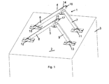
- Fig. 1 shows a holder for interior components in aircraft cabins with an acting on the top 2 of an interior component 3 connecting element.
- a connecting element 1 at least one towering arranged angular support 4, 5 is provided, the support struts 6, 7 and 8, 9, which are each end connected to the upper side 2 of the interior component 3 via a fixed bearing 10, 11 and 12, 13 articulated ,
- the support struts 6, 7 and 8, 9 of an angle support 4, 5 via a node element 14, 15 is connected.
- the support struts 6, 7 and 8, 9 with selectable lengths in such a manner to the node element 14, 15 connectable that by length selection of the support struts 6, 7 and 8, 9, the position of the node element 14, 15 with respect to the fixed bearings 10, 11th or 12, 13 of the support struts 6, 7 and 8, 9 is adjustable.
- the length variance of the support struts 6, 7 and 8, 9 is selected and matched to one another such that the node element 14, 15 is displaceable, for example, in a horizontal plane to the top 2.
- the included by the support struts 6, 7 and 8, 9 angle ⁇ is variable.
- connection point 16, 17 is provided on the node element 14, 15. It is essential to the extent that the connection point 16, 17 of the displacement of the node element 14, 15 by length variation of the support struts 6, 7 and 8, 9 follows.
- the connection point 16, 17 is, for example, an eyelet or in Fig. 1 shown tab formed with mounting hole, which is preferably in alignment with a support strut 6 and 8 respectively.
- the support struts 6, 7 and 8, 9 are preferably designed as profile struts.
- the articulation of the fixed bearing 10, 11, 12, 13 and the node element 14, 15 can be fixed or detachable.
- the node element 14, 15 is preferably designed as a hinge. Furthermore, it is preferred that two support struts 6, 7 and 8, 9 form an angle support 4, 5. As Fig. 1 shows, the angle bracket 4, 5 is formed as a three-pronged arc. The node element 14, 15 then preferably forms a relative to the top 2 of the interior component 3 movable bearing, ie a quasi-length variance certain floating bearing.
- connection point 16, 17 can be aligned with connection elements (not shown) of the fuselage structure of the aircraft.
- the attachment point 16, 17 can be positioned adjustable by length selection of the support struts 6, 7 and 8, 9 at a definable height h relative to the top 2 of the interior component 3.
- the mechanical design of the angle support 4, 5 can be selected depending on the load generated by the respective interior component 3.
- At least two parallel angle brackets 4, 5 are provided.
- adjacent angle supports 4, 5 can be coupled to each other by a respective reinforcing element 18, 19.
- the holder according to the invention can be used in the usual interior components for head-side attachment. Particularly preferred is the use as a galley holder, toilet holder, crew rest compartments.
- the support according to the invention is particularly suitable for interior components which introduce higher loads into the fuselage structure, e.g. due to their weight plus, if necessary, equipment.
- connection point 16, 17 may lie in a node of the node element 14, 15. Usable for this purpose, for example, provided with an eye bolt.
- the holder according to the invention can be combined with a foot-side attachment of the interior device components.
- the advantages of, for example, used mounting rails can be used, as an individual vote on desired cabin configurations by a length variation of the support struts 6, 7 and 8, 9 is possible.
Landscapes
- Engineering & Computer Science (AREA)
- Aviation & Aerospace Engineering (AREA)
- Connection Of Plates (AREA)
- Vehicle Step Arrangements And Article Storage (AREA)
Applications Claiming Priority (1)
| Application Number | Priority Date | Filing Date | Title |
|---|---|---|---|
| DE201010047385 DE102010047385A1 (de) | 2010-10-02 | 2010-10-02 | Halterung für Inneneinrichtungskomponenten in Flugzeugkabinen |
Publications (2)
| Publication Number | Publication Date |
|---|---|
| EP2436599A2 true EP2436599A2 (fr) | 2012-04-04 |
| EP2436599A3 EP2436599A3 (fr) | 2014-06-25 |
Family
ID=44759362
Family Applications (1)
| Application Number | Title | Priority Date | Filing Date |
|---|---|---|---|
| EP11007943.1A Withdrawn EP2436599A3 (fr) | 2010-10-02 | 2011-09-30 | Support pour composants d'aménagement intérieur dans des cabines d'avion |
Country Status (2)
| Country | Link |
|---|---|
| EP (1) | EP2436599A3 (fr) |
| DE (1) | DE102010047385A1 (fr) |
Cited By (4)
| Publication number | Priority date | Publication date | Assignee | Title |
|---|---|---|---|---|
| WO2013143673A1 (fr) * | 2012-03-26 | 2013-10-03 | Sell Gmbh | Structure de fixation pour cuisine de bord d'avion |
| EP3081487A1 (fr) * | 2015-04-15 | 2016-10-19 | Airbus Operations GmbH | Monument pour une cabine d'un véhicule et agencement de fixation |
| EP3081489A1 (fr) * | 2015-04-15 | 2016-10-19 | Airbus Operations GmbH | Kit de construction et procédé pour une structure de logement de borne pour une cabine de véhicule |
| FR3089495A1 (fr) | 2018-12-05 | 2020-06-12 | Airbus Operations | Portion d’aéronef comportant un équipement mobilier suspendu |
Citations (1)
| Publication number | Priority date | Publication date | Assignee | Title |
|---|---|---|---|---|
| DE102005054890A1 (de) | 2005-11-17 | 2007-05-24 | Airbus Deutschland Gmbh | Befestigungsstruktur zur Fixierung von Inneneinrichtungskomponenten einer Flugzeugpassagierkabine |
Family Cites Families (5)
| Publication number | Priority date | Publication date | Assignee | Title |
|---|---|---|---|---|
| US4077176A (en) * | 1976-10-18 | 1978-03-07 | Frederick Bauer | Truss joists |
| US6173550B1 (en) * | 1993-03-24 | 2001-01-16 | Daniel A. Tingley | Wood I-beam conditioned reinforcement panel |
| US6883753B1 (en) * | 2004-03-25 | 2005-04-26 | The Boeing Company | Overhead bin and monument attachment support system |
| US7497638B2 (en) * | 2006-11-09 | 2009-03-03 | The Boeing Company | Socket joint for tie-rod attachment system and method |
| US7967251B2 (en) * | 2008-03-18 | 2011-06-28 | The Boeing Company | Truss network for aircraft floor attachment |
-
2010
- 2010-10-02 DE DE201010047385 patent/DE102010047385A1/de not_active Ceased
-
2011
- 2011-09-30 EP EP11007943.1A patent/EP2436599A3/fr not_active Withdrawn
Patent Citations (1)
| Publication number | Priority date | Publication date | Assignee | Title |
|---|---|---|---|---|
| DE102005054890A1 (de) | 2005-11-17 | 2007-05-24 | Airbus Deutschland Gmbh | Befestigungsstruktur zur Fixierung von Inneneinrichtungskomponenten einer Flugzeugpassagierkabine |
Cited By (7)
| Publication number | Priority date | Publication date | Assignee | Title |
|---|---|---|---|---|
| WO2013143673A1 (fr) * | 2012-03-26 | 2013-10-03 | Sell Gmbh | Structure de fixation pour cuisine de bord d'avion |
| EP3081487A1 (fr) * | 2015-04-15 | 2016-10-19 | Airbus Operations GmbH | Monument pour une cabine d'un véhicule et agencement de fixation |
| EP3081489A1 (fr) * | 2015-04-15 | 2016-10-19 | Airbus Operations GmbH | Kit de construction et procédé pour une structure de logement de borne pour une cabine de véhicule |
| US10137989B2 (en) | 2015-04-15 | 2018-11-27 | Airbus Operations Gmbh | Construction kit and method for a housing structure of a monument for a vehicle cabin |
| US10137974B2 (en) | 2015-04-15 | 2018-11-27 | Airbus Operations Gmbh | Monument for a cabin of a vehicle, and fastening arrangement |
| FR3089495A1 (fr) | 2018-12-05 | 2020-06-12 | Airbus Operations | Portion d’aéronef comportant un équipement mobilier suspendu |
| US11542010B2 (en) | 2018-12-05 | 2023-01-03 | Airbus Operations (Sas) | Aircraft portion comprising a suspended item of furniture equipment |
Also Published As
| Publication number | Publication date |
|---|---|
| EP2436599A3 (fr) | 2014-06-25 |
| DE102010047385A1 (de) | 2012-04-05 |
Similar Documents
| Publication | Publication Date | Title |
|---|---|---|
| DE102005054890B4 (de) | Flugzeugrumpfstruktur mit einer Passagierkabine und einer Befestigungsstruktur zur Fixierung von Inneneinrichtungskomponenten in der Passagierkabine | |
| DE102010014302B4 (de) | Luftfahrzeug und Befestigungsanordnung für eine Fußbodenstruktur in einem Luftfahrzeug | |
| DE102008007838A1 (de) | Fußbodensystem für eine Rumpfzelle eines Flugzeugs | |
| WO1998039242A1 (fr) | Cabine d'ascenseur | |
| DE102007011611A1 (de) | Befestigungsanordnung für Verzurrbügel in einem Frachtraumboden eines Flugzeugs | |
| DE102005045181A1 (de) | Fußbodenstruktur für Flugzeuge | |
| EP2406115B1 (fr) | Panneau de plafond avec rail a rideau pour habitacle de moyen de transport procede et usage | |
| DE102010064100A1 (de) | Trennwand für eine Flugzeugkabine und Flugzeug | |
| DE102018123531A1 (de) | Verfahren zum Installieren von Systemkomponenten in einem Abschnitt eines Flugzeugrumpfs | |
| DE102014202287B4 (de) | Schienensystem zur Sitzmontage in einem Flugzeug | |
| DE102016111999A1 (de) | Modulares Schienensystem mit Klemmbefestigung | |
| EP2436599A2 (fr) | Support pour composants d'aménagement intérieur dans des cabines d'avion | |
| WO2016150891A1 (fr) | Module de plancher d'une soute d'aéronef | |
| DE102014202288B4 (de) | Schienensystem zur Sitzmontage in einem Flugzeug | |
| DE102018115776A1 (de) | Sitzgestellbefestigungsbaugruppe, Sitzgestell, Fahrzeugabschnitt und Fahrzeug mit einer Sitzgestellbefestigungsbaugruppe | |
| DE102016111994A1 (de) | Modulares Schienensystem | |
| DE102015117571B3 (de) | Bodenmodul eines Flugzeugfrachtraumes | |
| EP3807139B1 (fr) | Véhicule ferroviaire comprenant une caisse de véhicule et une structure de plafond disposée à l'intérieur de la caisse de véhicule | |
| DE102013106598A1 (de) | Schalungselement mit Schalungsplatten und Bewehrungskorb | |
| EP3326882A1 (fr) | Profil d'étanchéité pour construction de couverture anti-bruit d'un véhicule ferroviaire | |
| DE102009038036B4 (de) | Sitzanordnung für ein Fahrzeug | |
| DE102016223169B4 (de) | Schienenfahrzeug mit Fahrgasttisch | |
| DE102022104704A1 (de) | Vorrichtung zur Befestigung von Kabinenbauteilen an einer Flugzeugstruktur | |
| EP3730409B1 (fr) | Passerelle d'embarquement des passagers avec une cabine et un module de couplage | |
| DE202018105402U1 (de) | Flugzeugsitz |
Legal Events
| Date | Code | Title | Description |
|---|---|---|---|
| PUAI | Public reference made under article 153(3) epc to a published international application that has entered the european phase |
Free format text: ORIGINAL CODE: 0009012 |
|
| AK | Designated contracting states |
Kind code of ref document: A2 Designated state(s): AL AT BE BG CH CY CZ DE DK EE ES FI FR GB GR HR HU IE IS IT LI LT LU LV MC MK MT NL NO PL PT RO RS SE SI SK SM TR |
|
| AX | Request for extension of the european patent |
Extension state: BA ME |
|
| PUAL | Search report despatched |
Free format text: ORIGINAL CODE: 0009013 |
|
| AK | Designated contracting states |
Kind code of ref document: A3 Designated state(s): AL AT BE BG CH CY CZ DE DK EE ES FI FR GB GR HR HU IE IS IT LI LT LU LV MC MK MT NL NO PL PT RO RS SE SI SK SM TR |
|
| AX | Request for extension of the european patent |
Extension state: BA ME |
|
| RIC1 | Information provided on ipc code assigned before grant |
Ipc: B64D 11/00 20060101AFI20140516BHEP Ipc: B64D 11/04 20060101ALI20140516BHEP |
|
| 17P | Request for examination filed |
Effective date: 20141223 |
|
| RBV | Designated contracting states (corrected) |
Designated state(s): AL AT BE BG CH CY CZ DE DK EE ES FI FR GB GR HR HU IE IS IT LI LT LU LV MC MK MT NL NO PL PT RO RS SE SI SK SM TR |
|
| STAA | Information on the status of an ep patent application or granted ep patent |
Free format text: STATUS: THE APPLICATION IS DEEMED TO BE WITHDRAWN |
|
| 18D | Application deemed to be withdrawn |
Effective date: 20170401 |