EP2436599A2 - Holder for interior fitting components in aircraft cabins - Google Patents
Holder for interior fitting components in aircraft cabins Download PDFInfo
- Publication number
- EP2436599A2 EP2436599A2 EP11007943A EP11007943A EP2436599A2 EP 2436599 A2 EP2436599 A2 EP 2436599A2 EP 11007943 A EP11007943 A EP 11007943A EP 11007943 A EP11007943 A EP 11007943A EP 2436599 A2 EP2436599 A2 EP 2436599A2
- Authority
- EP
- European Patent Office
- Prior art keywords
- holder according
- support struts
- support
- interior
- holder
- Prior art date
- Legal status (The legal status is an assumption and is not a legal conclusion. Google has not performed a legal analysis and makes no representation as to the accuracy of the status listed.)
- Withdrawn
Links
Images


Classifications
-
- B—PERFORMING OPERATIONS; TRANSPORTING
- B64—AIRCRAFT; AVIATION; COSMONAUTICS
- B64D—EQUIPMENT FOR FITTING IN OR TO AIRCRAFT; FLIGHT SUITS; PARACHUTES; ARRANGEMENTS OR MOUNTING OF POWER PLANTS OR PROPULSION TRANSMISSIONS IN AIRCRAFT
- B64D11/00—Passenger or crew accommodation; Flight-deck installations not otherwise provided for
- B64D11/003—Stowage devices for passengers' personal luggage
-
- B—PERFORMING OPERATIONS; TRANSPORTING
- B64—AIRCRAFT; AVIATION; COSMONAUTICS
- B64D—EQUIPMENT FOR FITTING IN OR TO AIRCRAFT; FLIGHT SUITS; PARACHUTES; ARRANGEMENTS OR MOUNTING OF POWER PLANTS OR PROPULSION TRANSMISSIONS IN AIRCRAFT
- B64D11/00—Passenger or crew accommodation; Flight-deck installations not otherwise provided for
- B64D11/04—Galleys
Definitions
- the invention relates to a holder for interior components in aircraft cabins, in particular a galley holder, according to the preamble of claim 1.
- a fastening structure which comprises at least one system carrier which extends above the cabin floor at least over the distance between two ribs.
- a flexible fixation of the interior device components is made possible on the system carrier, in which a multiplicity of equidistantly spaced attachment means for fixing interior device components are configured along the latter, wherein the spacings of the attachment means are smaller than the spacings of the rib.
- the fasteners spaced one inch apart, interior components can be fixed in inches in the longitudinal direction of the passenger cabin at random locations, thereby ensuring an individual and easily convertible cabin configuration.
- the flexibility is achieved by a ratchet, which is generated by the spaced equally spaced on the system carrier fasteners.
- the fasteners are suspensions with fork-like widening fittings, which are attached via tabs on the system carrier.
- the fork-like design with stiffening rods gives the attachment structure the necessary rigidity.
- the disadvantage is that the known attachment structure is complex and the suspension does not allow a fixed head-side fixation of the interior components.
- the object of the invention is therefore to provide a holder for interior components in aircraft cabins, which allows a flexible head-side attachment of interior components in an aircraft cabin, which allows a firm fixation.
- a holder for interior components in aircraft cabins is created, which generates a position variance of a node of the bars by a length variance of the bars of a bearing assembly.
- An attachment point connected to the node can thus be aligned to attachment elements of a fuselage structure of the aircraft.
- the positioning of the interior device component for example a galley, is thus no longer predetermined by a rastering of the connection elements, since the position of the attachment point to the top side of the interior device component can be adjusted.
- the position of the connection point is freely adjustable by the length selection of the support struts.
- the holder according to the invention is inexpensive to manufacture and in use, since profile struts can be used as support struts. This is inexpensive meter goods.
- the holder according to the invention can be constructed from two standardized subgroups, since the node elements can be identical for all angle brackets. The flexibility realized by the mounting according to the invention with respect to the positioning of interior components in aircraft cabs is thus combined with a minimization of the cost.
- the node element is a hinge.
- This hinge is a bearing displaceable by the length variance of the support struts opposite the top of the interior fitting component, i. a quasi-length variance specific floating bearing.
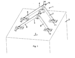
- Fig. 1 shows a holder for interior components in aircraft cabins with an acting on the top 2 of an interior component 3 connecting element.
- a connecting element 1 at least one towering arranged angular support 4, 5 is provided, the support struts 6, 7 and 8, 9, which are each end connected to the upper side 2 of the interior component 3 via a fixed bearing 10, 11 and 12, 13 articulated ,
- the support struts 6, 7 and 8, 9 of an angle support 4, 5 via a node element 14, 15 is connected.
- the support struts 6, 7 and 8, 9 with selectable lengths in such a manner to the node element 14, 15 connectable that by length selection of the support struts 6, 7 and 8, 9, the position of the node element 14, 15 with respect to the fixed bearings 10, 11th or 12, 13 of the support struts 6, 7 and 8, 9 is adjustable.
- the length variance of the support struts 6, 7 and 8, 9 is selected and matched to one another such that the node element 14, 15 is displaceable, for example, in a horizontal plane to the top 2.
- the included by the support struts 6, 7 and 8, 9 angle ⁇ is variable.
- connection point 16, 17 is provided on the node element 14, 15. It is essential to the extent that the connection point 16, 17 of the displacement of the node element 14, 15 by length variation of the support struts 6, 7 and 8, 9 follows.
- the connection point 16, 17 is, for example, an eyelet or in Fig. 1 shown tab formed with mounting hole, which is preferably in alignment with a support strut 6 and 8 respectively.
- the support struts 6, 7 and 8, 9 are preferably designed as profile struts.
- the articulation of the fixed bearing 10, 11, 12, 13 and the node element 14, 15 can be fixed or detachable.
- the node element 14, 15 is preferably designed as a hinge. Furthermore, it is preferred that two support struts 6, 7 and 8, 9 form an angle support 4, 5. As Fig. 1 shows, the angle bracket 4, 5 is formed as a three-pronged arc. The node element 14, 15 then preferably forms a relative to the top 2 of the interior component 3 movable bearing, ie a quasi-length variance certain floating bearing.
- connection point 16, 17 can be aligned with connection elements (not shown) of the fuselage structure of the aircraft.
- the attachment point 16, 17 can be positioned adjustable by length selection of the support struts 6, 7 and 8, 9 at a definable height h relative to the top 2 of the interior component 3.
- the mechanical design of the angle support 4, 5 can be selected depending on the load generated by the respective interior component 3.
- At least two parallel angle brackets 4, 5 are provided.
- adjacent angle supports 4, 5 can be coupled to each other by a respective reinforcing element 18, 19.
- the holder according to the invention can be used in the usual interior components for head-side attachment. Particularly preferred is the use as a galley holder, toilet holder, crew rest compartments.
- the support according to the invention is particularly suitable for interior components which introduce higher loads into the fuselage structure, e.g. due to their weight plus, if necessary, equipment.
- connection point 16, 17 may lie in a node of the node element 14, 15. Usable for this purpose, for example, provided with an eye bolt.
- the holder according to the invention can be combined with a foot-side attachment of the interior device components.
- the advantages of, for example, used mounting rails can be used, as an individual vote on desired cabin configurations by a length variation of the support struts 6, 7 and 8, 9 is possible.
Abstract
Description
Die Erfindung betrifft eine Halterung für Inneneinrichtungskomponenten in Flugzeugkabinen, insbesondere eine Galley-Halterung, nach dem Oberbegriff des Anspruchs 1.The invention relates to a holder for interior components in aircraft cabins, in particular a galley holder, according to the preamble of
Aus
Zur kopfseitigen Befestigung wurden in aller Regel an der oberen Rumpfstruktur des Flugzeuges individuell auf die jeweiligen Inneneinrichtungskomponenten und deren Einbauort ausgelegte Stabwerke sowie speziell gefräste Strukturen eingesetzt, die die von den Komponenten hervorgerufenen Belastungen in den Flugzeugrumpf einleiten. Diese herkömmliche Befestigung von Inneneinrichtungskomponenten führte somit zu einer verhältnismäßig unflexiblen Kabinenkonfiguration, die sich nur mit größerem baulichem Aufwand umrüsten ließ. Eine Veränderung der Kabinenkonfiguration führte daher schon aus Gründen der strukturellen Anbindung der Inneneinrichtungskomponenten unter Verwendung der speziell ausgelegten Stabwerke sowie entsprechend gefräster Strukturen zu einer großen Anzahl speziell zu ersetzender Bauteile.For the head attachment were usually at the upper fuselage structure of the Aircraft individually adapted to the respective interior furnishings components and their installation designed trusses and specially milled structures that introduce the stresses caused by the components in the fuselage. This conventional attachment of interior components thus resulted in a relatively inflexible cabin configuration that could only be retrofitted with a great deal of construction effort. Therefore, a change in the cabin configuration has already led to a large number of components to be replaced especially for reasons of structural connection of the interior device components using the specially designed frameworks and correspondingly milled structures.
Zum Erreichen einer verhältnismäßig flexiblen kopfseitigen Befestigung von Inneneinrichtungskomponenten in einer Passagierkabine ist daher bekannt, eine Befestigungsstruktur zu verwenden, die zumindest einen Systemträger umfasst, der sich oberhalb des Kabinenbodens zumindest über den Abstand zweier Spante erstreckt. An dem Systemträger wird eine flexible Fixierung der Inneneinrichtungskomponenten ermöglicht, in dem entlang diesem eine Vielzahl an in gleichmäßigen Abständen voneinander beabstandeten Befestigungsmitteln zur Fixierung von Inneneinrichtungskomponenten ausgestaltet ist, wobei die Abstände der Befestigungsmittel kleiner sind als die Abstände der Spante. Indem die Befestigungsmittel beispielsweise einen gegenseitigen Abstand von einem Inch zueinander aufweisen, lassen sich Inneneinrichtungskomponenten inchweise in Längsrichtung der Passagierkabine an beliebigen Stellen fixieren, wodurch eine individuelle und leicht umrüstbare Kabinenkonfiguration sichergestellt werden kann. Die Flexibilität wird durch eine Rasterung erzielt, die durch die an dem Systemträger in gleichmäßigen Abständen voneinander beabstandeten Befestigungsmittel erzeugt wird. Bei den Befestigungsmitteln handelt es sich um Abhängungen mit gabelartig sich aufweitenden Beschlägen, die über Laschen am Systemträger befestigt sind. Die gabelartige Ausbildung mit Aussteifungsstangen verleiht der Befestigungsstruktur die notwendige Steifigkeit.In order to achieve a relatively flexible head-side attachment of interior components in a passenger cabin, it is therefore known to use a fastening structure which comprises at least one system carrier which extends above the cabin floor at least over the distance between two ribs. A flexible fixation of the interior device components is made possible on the system carrier, in which a multiplicity of equidistantly spaced attachment means for fixing interior device components are configured along the latter, wherein the spacings of the attachment means are smaller than the spacings of the rib. For example, by having the fasteners spaced one inch apart, interior components can be fixed in inches in the longitudinal direction of the passenger cabin at random locations, thereby ensuring an individual and easily convertible cabin configuration. The flexibility is achieved by a ratchet, which is generated by the spaced equally spaced on the system carrier fasteners. The fasteners are suspensions with fork-like widening fittings, which are attached via tabs on the system carrier. The fork-like design with stiffening rods gives the attachment structure the necessary rigidity.
Nachteilig ist, dass die bekannte Befestigungsstruktur aufwändig ist und die Aufhängung keine feste kopfseitige Fixierung der Inneneinrichtungskomponenten ermöglicht.The disadvantage is that the known attachment structure is complex and the suspension does not allow a fixed head-side fixation of the interior components.
Aufgabe der Erfindung ist es daher, eine Halterung für Inneneinrichtungskomponenten in Flugzeugkabinen zu schaffen, die eine flexible kopfseitige Befestigung von Inneneinrichtungskomponenten in einer Flugzeugkabine erlaubt, die eine feste Fixierung ermöglicht.The object of the invention is therefore to provide a holder for interior components in aircraft cabins, which allows a flexible head-side attachment of interior components in an aircraft cabin, which allows a firm fixation.
Diese Aufgabe wird durch die Merkmale des Anspruchs 1 gelöst.This object is solved by the features of
Hierdurch wird eine Halterung für Inneneinrichtungskomponenten in Flugzeugkabinen geschaffen, die durch eine Längenvarianz der Stäbe einer Festlageranordnung eine Lagenvarianz eines Knotenpunktes der Stäbe erzeugt. Eine mit dem Knotenpunkt verbundene Anbindungsstelle ist so zu Anbindungselementen einer Rumpfstruktur des Flugzeuges ausrichtbar.In this way, a holder for interior components in aircraft cabins is created, which generates a position variance of a node of the bars by a length variance of the bars of a bearing assembly. An attachment point connected to the node can thus be aligned to attachment elements of a fuselage structure of the aircraft.
Die Positionierung der Inneneinrichtungskomponente, beispielsweise einer Galley, ist damit nicht mehr durch eine Rasterung der Anbindungselemente vorgegeben, da die Lage der Anbindungsstelle zur Oberseite der Inneneinrichtungskomponente einstellbar ist. Die Position der Anbindungsstelle ist durch die Längenwahl der Stützstreben frei einstellbar.The positioning of the interior device component, for example a galley, is thus no longer predetermined by a rastering of the connection elements, since the position of the attachment point to the top side of the interior device component can be adjusted. The position of the connection point is freely adjustable by the length selection of the support struts.
Die erfindungsgemäße Halterung ist kostengünstig in der Herstellung und im Einsatz, da als Stützstreben Profilstreben eingesetzt werden können. Hierbei handelt es sich um kostengünstige Meterware. Die erfindungsgemäße Halterung kann aus zwei standardisierten Teilgruppen aufgebaut werden, da die Knotenelemente für alle Winkelstützen identisch sein können. Die durch die erfindungsgemäße Halterung realisierte Flexibilität bezüglich der Positionierung von Inneneinrichtungskomponenten in Flugzeugkabinen ist folglich kombiniert mit einer Minimierung des Kostenaufwandes.The holder according to the invention is inexpensive to manufacture and in use, since profile struts can be used as support struts. This is inexpensive meter goods. The holder according to the invention can be constructed from two standardized subgroups, since the node elements can be identical for all angle brackets. The flexibility realized by the mounting according to the invention with respect to the positioning of interior components in aircraft cabs is thus combined with a minimization of the cost.
Vorzugsweise ist das Knotenelement ein Gelenk. Dieses Gelenk ist ein durch die Längenvarianz der Stützstreben gegenüber der Oberseite der Inneneinrichtungskomponente verschiebbares Lager, d.h. ein quasi Längenvarianz bestimmtes Loslager.Preferably, the node element is a hinge. This hinge is a bearing displaceable by the length variance of the support struts opposite the top of the interior fitting component, i. a quasi-length variance specific floating bearing.
Weitere Ausgestaltungen und Vorteile der Erfindung sind der nachfolgenden Beschreibung und den Unteransprüchen zu entnehmen.Further embodiments and advantages of the invention will become apparent from the following description and the dependent claims.
Die Erfindung wird nachstehend anhand der in den beigefügten Abbildungen dargestellten Ausführungsbeispiele näher erläutert.
-
Fig. 1 zeigt schematisch eine perspektivische Ansicht eines ersten Ausführungsbeispiels einer erfindungsgemäßen Halterung, -
Fig. 2 zeigt schematisch eine perspektivische Ansicht eines zweiten Ausführungsbeispiels einer erfindungsgemäßen Halterung, -
Fig. 3 zeigt schematisch eine perspektivische Ansicht eines dritten Ausführungsbeispiels einer erfindungsgemäßen Halterung, -
Fig. 4 zeigt schematisch Längenvariationen der Stützstrebe, -
Fig. 5 zeigt schematisch eine perspektivische Ansicht eines vierten Ausführungsbeispiels einer erfindungsgemäßen Halterung.
-
Fig. 1 shows schematically a perspective view of a first embodiment of a holder according to the invention, -
Fig. 2 shows schematically a perspective view of a second embodiment of a holder according to the invention, -
Fig. 3 shows schematically a perspective view of a third embodiment of a holder according to the invention, -
Fig. 4 shows schematically length variations of the support strut, -
Fig. 5 schematically shows a perspective view of a fourth embodiment of a holder according to the invention.
Als Verbindungselement 1 ist mindestens eine aufragend angeordnete Winkelstütze 4, 5 vorgesehen, die Stützstreben 6, 7 bzw. 8, 9 aufweist, die jeweils endseitig an der Oberseite 2 der Inneneinrichtungskomponente 3 über ein Festlager 10, 11 bzw. 12, 13 gelenkig angeschlossen sind.As a connecting
An dem dem jeweiligen Festlager 10, 11 bzw. 12, 13 gegenüberliegenden Ende sind die Stützstreben 6, 7 bzw. 8, 9 einer Winkelstütze 4, 5 über ein Knotenelement 14, 15 verbunden. Dabei sind die Stützstreben 6, 7 bzw. 8, 9 mit wählbaren Längen derart an das Knotenelement 14, 15 anschließbar, dass durch Längenwahl der Stützstreben 6, 7 bzw. 8, 9 die Lage des Knotenelements 14, 15 gegenüber den Festlagern 10, 11 bzw. 12, 13 der Stützstreben 6, 7 bzw. 8, 9 einstellbar ist.At the respective fixed bearing 10, 11 and 12, 13 opposite end the
Vorzugsweise ist die Längenvarianz der Stützstreben 6, 7 bzw. 8, 9 derart gewählt und aufeinander abgestimmt, dass das Knotenelement 14, 15 beispielsweise in einer zur Oberseite 2 horizontalen Ebene verschiebbar ist. Der von den Stützstreben 6, 7 bzw. 8, 9 eingeschlossene Winkel α ist dazu veränderlich.Preferably, the length variance of the
Zur Befestigung des Verbindungselementes 1 an einer Rumpfstruktur eines Flugzeuges ist eine Anbindungsstelle 16, 17 am Knotenelement 14, 15 vorgesehen. Wesentlich ist insoweit, dass die Anbindungsstelle 16, 17 der Verschiebung des Knotenelementes 14, 15 durch Längenvariation der Stützstreben 6, 7 bzw. 8, 9 folgt. Die Anbindungsstelle 16, 17 wird beispielsweise von einer Öse oder einer in
Die Stützstreben 6, 7 bzw. 8, 9 sind vorzugsweise als Profilstreben ausgebildet. Die Anlenkung an die Festlager 10, 11, 12, 13 und das Knotenelement 14, 15 kann fest oder lösbar erfolgen.The
Das Knotenelement 14, 15 ist vorzugsweise als Gelenk ausgebildet. Weiterhin bevorzugt ist, dass jeweils zwei Stützstreben 6, 7 bzw. 8, 9 eine Winkelstütze 4, 5 bilden. Wie
Wie
Die mechanische Auslegung der Winkelstütze 4, 5 ist in Abhängigkeit von der durch die jeweilige Inneneinrichtungskomponente 3 erzeugten Belastung wählbar.The mechanical design of the
Vorzugsweise sind mindestens zwei parallel angeordnete Winkelstützen 4, 5 vorgesehen. Wie
Die erfindungsgemäße Halterung kann bei den üblichen Inneneinrichtungskomponenten zur kopfseitigen Befestigung verwendet werden. Besonders bevorzugt ist die Verwendung als Galley-Halterung, Toiletten-Halterung, Crewrest-Compartments. Die erfindungsgemäße Halterung eignet sich insbesondere für Inneneinrichtungskomponenten, die höhere Lasten in die Rumpfstruktur einleiten, z.B. aufgrund ihres Gewichtes zuzüglich gegebenenfalls Bestückung.The holder according to the invention can be used in the usual interior components for head-side attachment. Particularly preferred is the use as a galley holder, toilet holder, crew rest compartments. The support according to the invention is particularly suitable for interior components which introduce higher loads into the fuselage structure, e.g. due to their weight plus, if necessary, equipment.
Wie
Die erfindungsgemäße Halterung kann mit einer fußseitigen Befestigung der Inneneinrichtungskomponenten kombiniert werden. Die Vorteile von beispielsweise eingesetzten Befestigungsschienen können genutzt werden, da eine individuelle Abstimmung auf gewünschte Kabinenkonfigurationen durch eine Längenvariation der Stützstreben 6, 7 bzw. 8, 9 möglich ist.The holder according to the invention can be combined with a foot-side attachment of the interior device components. The advantages of, for example, used mounting rails can be used, as an individual vote on desired cabin configurations by a length variation of the support struts 6, 7 and 8, 9 is possible.
Claims (8)
Applications Claiming Priority (1)
| Application Number | Priority Date | Filing Date | Title |
|---|---|---|---|
| DE201010047385 DE102010047385A1 (en) | 2010-10-02 | 2010-10-02 | Holder for interior components in aircraft cabins |
Publications (2)
| Publication Number | Publication Date |
|---|---|
| EP2436599A2 true EP2436599A2 (en) | 2012-04-04 |
| EP2436599A3 EP2436599A3 (en) | 2014-06-25 |
Family
ID=44759362
Family Applications (1)
| Application Number | Title | Priority Date | Filing Date |
|---|---|---|---|
| EP11007943.1A Withdrawn EP2436599A3 (en) | 2010-10-02 | 2011-09-30 | Holder for interior fitting components in aircraft cabins |
Country Status (2)
| Country | Link |
|---|---|
| EP (1) | EP2436599A3 (en) |
| DE (1) | DE102010047385A1 (en) |
Cited By (4)
| Publication number | Priority date | Publication date | Assignee | Title |
|---|---|---|---|---|
| WO2013143673A1 (en) * | 2012-03-26 | 2013-10-03 | Sell Gmbh | Fastening structure for an aircraft galley |
| EP3081489A1 (en) * | 2015-04-15 | 2016-10-19 | Airbus Operations GmbH | Construction kit and method for a housing structure of a monument for a vehicle cabin |
| EP3081487A1 (en) * | 2015-04-15 | 2016-10-19 | Airbus Operations GmbH | Monument for a cabin of a vehicle, and fastening arrangement |
| FR3089495A1 (en) | 2018-12-05 | 2020-06-12 | Airbus Operations | Portion of aircraft with suspended movable equipment |
Citations (1)
| Publication number | Priority date | Publication date | Assignee | Title |
|---|---|---|---|---|
| DE102005054890A1 (en) | 2005-11-17 | 2007-05-24 | Airbus Deutschland Gmbh | Fixing structure for fixing interior components of an aircraft passenger cabin |
Family Cites Families (5)
| Publication number | Priority date | Publication date | Assignee | Title |
|---|---|---|---|---|
| US4077176A (en) * | 1976-10-18 | 1978-03-07 | Frederick Bauer | Truss joists |
| US6173550B1 (en) * | 1993-03-24 | 2001-01-16 | Daniel A. Tingley | Wood I-beam conditioned reinforcement panel |
| US6883753B1 (en) * | 2004-03-25 | 2005-04-26 | The Boeing Company | Overhead bin and monument attachment support system |
| US7497638B2 (en) * | 2006-11-09 | 2009-03-03 | The Boeing Company | Socket joint for tie-rod attachment system and method |
| US7967251B2 (en) * | 2008-03-18 | 2011-06-28 | The Boeing Company | Truss network for aircraft floor attachment |
-
2010
- 2010-10-02 DE DE201010047385 patent/DE102010047385A1/en not_active Ceased
-
2011
- 2011-09-30 EP EP11007943.1A patent/EP2436599A3/en not_active Withdrawn
Patent Citations (1)
| Publication number | Priority date | Publication date | Assignee | Title |
|---|---|---|---|---|
| DE102005054890A1 (en) | 2005-11-17 | 2007-05-24 | Airbus Deutschland Gmbh | Fixing structure for fixing interior components of an aircraft passenger cabin |
Cited By (7)
| Publication number | Priority date | Publication date | Assignee | Title |
|---|---|---|---|---|
| WO2013143673A1 (en) * | 2012-03-26 | 2013-10-03 | Sell Gmbh | Fastening structure for an aircraft galley |
| EP3081489A1 (en) * | 2015-04-15 | 2016-10-19 | Airbus Operations GmbH | Construction kit and method for a housing structure of a monument for a vehicle cabin |
| EP3081487A1 (en) * | 2015-04-15 | 2016-10-19 | Airbus Operations GmbH | Monument for a cabin of a vehicle, and fastening arrangement |
| US10137974B2 (en) | 2015-04-15 | 2018-11-27 | Airbus Operations Gmbh | Monument for a cabin of a vehicle, and fastening arrangement |
| US10137989B2 (en) | 2015-04-15 | 2018-11-27 | Airbus Operations Gmbh | Construction kit and method for a housing structure of a monument for a vehicle cabin |
| FR3089495A1 (en) | 2018-12-05 | 2020-06-12 | Airbus Operations | Portion of aircraft with suspended movable equipment |
| US11542010B2 (en) | 2018-12-05 | 2023-01-03 | Airbus Operations (Sas) | Aircraft portion comprising a suspended item of furniture equipment |
Also Published As
| Publication number | Publication date |
|---|---|
| EP2436599A3 (en) | 2014-06-25 |
| DE102010047385A1 (en) | 2012-04-05 |
Similar Documents
| Publication | Publication Date | Title |
|---|---|---|
| DE102005054890B4 (en) | An aircraft fuselage structure with a passenger cabin and a mounting structure for fixing interior components in the passenger cabin | |
| DE102008007838B4 (en) | Floor system for a fuselage cell of an aircraft | |
| DE102007011611B4 (en) | Fixing arrangement for lashing strap in a cargo hold floor of an aircraft | |
| DE102010014302B4 (en) | Aircraft and mounting arrangement for a floor structure in an aircraft | |
| WO1998039242A1 (en) | Elevator car | |
| DE102005045181A1 (en) | Floor structure for aircraft | |
| EP2406115B1 (en) | Ceiling panel having curtain rail in a transport means cabin, method and use | |
| DE102010064100A1 (en) | Partition for an aircraft cabin and aircraft | |
| DE102016111999A1 (en) | Modular rail system with clamp attachment | |
| EP2436599A2 (en) | Holder for interior fitting components in aircraft cabins | |
| DE102018123531A1 (en) | Method for installing system components in a section of an aircraft fuselage | |
| DE102014202287A1 (en) | Rail system for seat mounting in an aircraft | |
| WO2016150891A1 (en) | Floor module of an aircraft cargo hold | |
| DE102014202288B4 (en) | Rail system for mounting seats in an airplane | |
| DE102018115776A1 (en) | Seat frame mounting assembly, seat frame, vehicle section and vehicle with a seat frame mounting assembly | |
| DE102007018326B4 (en) | Storage for mounting stairs in an airplane | |
| DE102016111994A1 (en) | Modular rail system | |
| DE102017220378A1 (en) | Floor assembly with monolithic floor element and aircraft area and aircraft with a floor assembly | |
| DE102015117571B3 (en) | Floor module of an aircraft cargo hold | |
| EP3807139B1 (en) | Rail vehicle car having a car body and a ceiling frame arranged within the car body | |
| DE102013106598A1 (en) | Formwork element for use as prefabricated unit of ring girder casing in construction site, has reinforcing cage arranged between formwork boards, and spacers for fixing minimum distance between cage and respective formwork board | |
| EP3326882A1 (en) | Sealing profile for housing structures of a rail vehicle | |
| DE102009038036B4 (en) | Seat arrangement for a vehicle | |
| WO2023161454A1 (en) | Device for fastening cabin components to an aircraft structure | |
| EP3730409B1 (en) | Passenger boarding bridge with a cabin and a coupling module |
Legal Events
| Date | Code | Title | Description |
|---|---|---|---|
| PUAI | Public reference made under article 153(3) epc to a published international application that has entered the european phase |
Free format text: ORIGINAL CODE: 0009012 |
|
| AK | Designated contracting states |
Kind code of ref document: A2 Designated state(s): AL AT BE BG CH CY CZ DE DK EE ES FI FR GB GR HR HU IE IS IT LI LT LU LV MC MK MT NL NO PL PT RO RS SE SI SK SM TR |
|
| AX | Request for extension of the european patent |
Extension state: BA ME |
|
| PUAL | Search report despatched |
Free format text: ORIGINAL CODE: 0009013 |
|
| AK | Designated contracting states |
Kind code of ref document: A3 Designated state(s): AL AT BE BG CH CY CZ DE DK EE ES FI FR GB GR HR HU IE IS IT LI LT LU LV MC MK MT NL NO PL PT RO RS SE SI SK SM TR |
|
| AX | Request for extension of the european patent |
Extension state: BA ME |
|
| RIC1 | Information provided on ipc code assigned before grant |
Ipc: B64D 11/00 20060101AFI20140516BHEP Ipc: B64D 11/04 20060101ALI20140516BHEP |
|
| 17P | Request for examination filed |
Effective date: 20141223 |
|
| RBV | Designated contracting states (corrected) |
Designated state(s): AL AT BE BG CH CY CZ DE DK EE ES FI FR GB GR HR HU IE IS IT LI LT LU LV MC MK MT NL NO PL PT RO RS SE SI SK SM TR |
|
| STAA | Information on the status of an ep patent application or granted ep patent |
Free format text: STATUS: THE APPLICATION IS DEEMED TO BE WITHDRAWN |
|
| 18D | Application deemed to be withdrawn |
Effective date: 20170401 |