EP2435849B1 - Measuring apparatus - Google Patents
Measuring apparatus Download PDFInfo
- Publication number
- EP2435849B1 EP2435849B1 EP10722791.0A EP10722791A EP2435849B1 EP 2435849 B1 EP2435849 B1 EP 2435849B1 EP 10722791 A EP10722791 A EP 10722791A EP 2435849 B1 EP2435849 B1 EP 2435849B1
- Authority
- EP
- European Patent Office
- Prior art keywords
- delay
- sum
- circuit
- probe
- output
- Prior art date
- Legal status (The legal status is an assumption and is not a legal conclusion. Google has not performed a legal analysis and makes no representation as to the accuracy of the status listed.)
- Active
Links
Images


Classifications
-
- G—PHYSICS
- G01—MEASURING; TESTING
- G01S—RADIO DIRECTION-FINDING; RADIO NAVIGATION; DETERMINING DISTANCE OR VELOCITY BY USE OF RADIO WAVES; LOCATING OR PRESENCE-DETECTING BY USE OF THE REFLECTION OR RERADIATION OF RADIO WAVES; ANALOGOUS ARRANGEMENTS USING OTHER WAVES
- G01S7/00—Details of systems according to groups G01S13/00, G01S15/00, G01S17/00
- G01S7/52—Details of systems according to groups G01S13/00, G01S15/00, G01S17/00 of systems according to group G01S15/00
- G01S7/52017—Details of systems according to groups G01S13/00, G01S15/00, G01S17/00 of systems according to group G01S15/00 particularly adapted to short-range imaging
- G01S7/52046—Techniques for image enhancement involving transmitter or receiver
-
- G—PHYSICS
- G01—MEASURING; TESTING
- G01S—RADIO DIRECTION-FINDING; RADIO NAVIGATION; DETERMINING DISTANCE OR VELOCITY BY USE OF RADIO WAVES; LOCATING OR PRESENCE-DETECTING BY USE OF THE REFLECTION OR RERADIATION OF RADIO WAVES; ANALOGOUS ARRANGEMENTS USING OTHER WAVES
- G01S15/00—Systems using the reflection or reradiation of acoustic waves, e.g. sonar systems
- G01S15/88—Sonar systems specially adapted for specific applications
- G01S15/89—Sonar systems specially adapted for specific applications for mapping or imaging
- G01S15/8906—Short-range imaging systems; Acoustic microscope systems using pulse-echo techniques
- G01S15/8909—Short-range imaging systems; Acoustic microscope systems using pulse-echo techniques using a static transducer configuration
- G01S15/8915—Short-range imaging systems; Acoustic microscope systems using pulse-echo techniques using a static transducer configuration using a transducer array
-
- G—PHYSICS
- G01—MEASURING; TESTING
- G01S—RADIO DIRECTION-FINDING; RADIO NAVIGATION; DETERMINING DISTANCE OR VELOCITY BY USE OF RADIO WAVES; LOCATING OR PRESENCE-DETECTING BY USE OF THE REFLECTION OR RERADIATION OF RADIO WAVES; ANALOGOUS ARRANGEMENTS USING OTHER WAVES
- G01S15/00—Systems using the reflection or reradiation of acoustic waves, e.g. sonar systems
- G01S15/88—Sonar systems specially adapted for specific applications
- G01S15/89—Sonar systems specially adapted for specific applications for mapping or imaging
- G01S15/8906—Short-range imaging systems; Acoustic microscope systems using pulse-echo techniques
- G01S15/8934—Short-range imaging systems; Acoustic microscope systems using pulse-echo techniques using a dynamic transducer configuration
- G01S15/8945—Short-range imaging systems; Acoustic microscope systems using pulse-echo techniques using a dynamic transducer configuration using transducers mounted for linear mechanical movement
-
- G—PHYSICS
- G01—MEASURING; TESTING
- G01S—RADIO DIRECTION-FINDING; RADIO NAVIGATION; DETERMINING DISTANCE OR VELOCITY BY USE OF RADIO WAVES; LOCATING OR PRESENCE-DETECTING BY USE OF THE REFLECTION OR RERADIATION OF RADIO WAVES; ANALOGOUS ARRANGEMENTS USING OTHER WAVES
- G01S15/00—Systems using the reflection or reradiation of acoustic waves, e.g. sonar systems
- G01S15/88—Sonar systems specially adapted for specific applications
- G01S15/89—Sonar systems specially adapted for specific applications for mapping or imaging
- G01S15/8906—Short-range imaging systems; Acoustic microscope systems using pulse-echo techniques
- G01S15/8997—Short-range imaging systems; Acoustic microscope systems using pulse-echo techniques using synthetic aperture techniques
-
- G—PHYSICS
- G01—MEASURING; TESTING
- G01S—RADIO DIRECTION-FINDING; RADIO NAVIGATION; DETERMINING DISTANCE OR VELOCITY BY USE OF RADIO WAVES; LOCATING OR PRESENCE-DETECTING BY USE OF THE REFLECTION OR RERADIATION OF RADIO WAVES; ANALOGOUS ARRANGEMENTS USING OTHER WAVES
- G01S7/00—Details of systems according to groups G01S13/00, G01S15/00, G01S17/00
- G01S7/52—Details of systems according to groups G01S13/00, G01S15/00, G01S17/00 of systems according to group G01S15/00
- G01S7/52017—Details of systems according to groups G01S13/00, G01S15/00, G01S17/00 of systems according to group G01S15/00 particularly adapted to short-range imaging
- G01S7/52085—Details related to the ultrasound signal acquisition, e.g. scan sequences
-
- G—PHYSICS
- G10—MUSICAL INSTRUMENTS; ACOUSTICS
- G10K—SOUND-PRODUCING DEVICES; METHODS OR DEVICES FOR PROTECTING AGAINST, OR FOR DAMPING, NOISE OR OTHER ACOUSTIC WAVES IN GENERAL; ACOUSTICS NOT OTHERWISE PROVIDED FOR
- G10K11/00—Methods or devices for transmitting, conducting or directing sound in general; Methods or devices for protecting against, or for damping, noise or other acoustic waves in general
- G10K11/18—Methods or devices for transmitting, conducting or directing sound
- G10K11/26—Sound-focusing or directing, e.g. scanning
- G10K11/34—Sound-focusing or directing, e.g. scanning using electrical steering of transducer arrays, e.g. beam steering
- G10K11/341—Circuits therefor
- G10K11/346—Circuits therefor using phase variation
-
- G—PHYSICS
- G10—MUSICAL INSTRUMENTS; ACOUSTICS
- G10K—SOUND-PRODUCING DEVICES; METHODS OR DEVICES FOR PROTECTING AGAINST, OR FOR DAMPING, NOISE OR OTHER ACOUSTIC WAVES IN GENERAL; ACOUSTICS NOT OTHERWISE PROVIDED FOR
- G10K11/00—Methods or devices for transmitting, conducting or directing sound in general; Methods or devices for protecting against, or for damping, noise or other acoustic waves in general
- G10K11/18—Methods or devices for transmitting, conducting or directing sound
- G10K11/26—Sound-focusing or directing, e.g. scanning
- G10K11/35—Sound-focusing or directing, e.g. scanning using mechanical steering of transducers or their beams
- G10K11/352—Sound-focusing or directing, e.g. scanning using mechanical steering of transducers or their beams by moving the transducer
-
- A—HUMAN NECESSITIES
- A61—MEDICAL OR VETERINARY SCIENCE; HYGIENE
- A61B—DIAGNOSIS; SURGERY; IDENTIFICATION
- A61B8/00—Diagnosis using ultrasonic, sonic or infrasonic waves
- A61B8/48—Diagnostic techniques
- A61B8/483—Diagnostic techniques involving the acquisition of a 3D volume of data
-
- G—PHYSICS
- G01—MEASURING; TESTING
- G01S—RADIO DIRECTION-FINDING; RADIO NAVIGATION; DETERMINING DISTANCE OR VELOCITY BY USE OF RADIO WAVES; LOCATING OR PRESENCE-DETECTING BY USE OF THE REFLECTION OR RERADIATION OF RADIO WAVES; ANALOGOUS ARRANGEMENTS USING OTHER WAVES
- G01S15/00—Systems using the reflection or reradiation of acoustic waves, e.g. sonar systems
- G01S15/88—Sonar systems specially adapted for specific applications
- G01S15/89—Sonar systems specially adapted for specific applications for mapping or imaging
- G01S15/8906—Short-range imaging systems; Acoustic microscope systems using pulse-echo techniques
- G01S15/8993—Three dimensional imaging systems
Definitions
- the present invention relates to a measuring apparatus which obtains information inside an object using an acoustic wave, and more particularly, to a measuring apparatus having a probe that is mechanically scanned.
- an x-ray mammography apparatus As an effective image diagnosis apparatus for early detection of breast cancer, there is known an x-ray mammography apparatus. Further, in recent years, there is developed a photoacoustic imaging method in which a pulse laser beam is irradiated onto a living body instead of an X-ray, so as to image a three-dimensional structure inside the living body based on a photoacoustic wave induced by thermal expansion of an optical absorber inside the living body. This apparatus has received attention as a new mammography apparatus that may easily diagnose a potential tumor such as an abnormal growth of new blood vessels.
- Such a mammography apparatus has a feature that an abnormal region which is difficult to detect by other apparatus may be detected as a clear image.
- Japanese Patent Application Laid-Open No. 2006-102494 and Japanese Patent Application Laid-Open No. 2008-161283 disclose examples of an x-ray mammography apparatus incorporating an ultrasonic diagnosis apparatus.
- a breast as an object is fixed to a compression plate, and a mammography sensor and an ultrasonic probe are moved mechanically for scanning along the compression plate so that a mammography image and a three-dimensional ultrasonic echo image of the entire breast may be obtained simultaneously.
- this method has a problem that image resolution in the elevation direction significantly reduces as compared with image resolution in a slice plane.
- a first reason is that if the mechanical scan speed by the probe is decreased so as to reduce a pitch of obtaining the cross-sectional slice images, it may increase a physical load to the human object. Therefore, it is necessary to lower the pixel density in the elevation direction to some extent.
- a second reason is that effective angular aperture of the one-dimensionally arranged probe in the elevation direction is smaller than that in the arrangement direction, so that a reconstruction resolution in the elevation direction is deteriorated. If a two-dimensionally arranged probe is used, this problem may be alleviated to some extent.
- the number of transmission and reception elements increases, which leads to another problem that a necessary electric circuit scale increases, making it difficult to achieve the practical use of the apparatus in terms of cost.
- the JP 2008-080093 A discloses an ultrasonic probe of a short-axis scan type in which a plurality of piezoelectric elements in strips are arranged in the long-axis direction as the width direction of the piezoelectric elements to form a flat piezoelectric element group, and the piezoelectric element group is housed in a sealed container filled with fluid as ultrasonic wave medium, so that the piezoelectric element group is mechanically scanned in the short-axis direction as the length direction of the piezoelectric elements. The piezoelectric element group is moved straight in the short-axis direction for mechanical scan.
- the US 5 186 175 A discloses an ultrasonic probe with transducers one-dimensionally arranged in long axis direction, wherein the probe is mechanically moved in a short axis direction to scan an object.
- the EP 0 087 318 A2 discloses an ultrasonic diagnostic apparatus using an array type transducer probe, wherein improved tomographic image resolution is desired by electronically focusing ultrasonic wave toward an object to be examined in both directions, i.e., the array direction and the lens direction.
- the signals received from the probe are synthesized in phase with respect to each other via delay lines having predetermined delay times to obtain first scanned signals in real time, so that focusing the reflected ultrasonic wave can be electronically accomplished in the array direction.
- the probe is mechanically moved to a given position in the lens direction normal to the array direction. Then a second scanning operation is accomplished to obtain similar first scanned signals.
- All of the first scanned signals are processed by a delay time control circuit, digitized, and then stored. Finally, all of the stored first scanned signals are read out and synthesized in phase with respect to each other by an adder circuit to obtain second scanned signals, so that focusing the reflected ultrasonic wave can be accomplished in the lens direction. The resultant second scanned signals are converted into analogue signals to be displayed as a tomographic image of the desired diagnostic part in the object.
- An object of the present invention is to improve image resolution in the elevation direction with a simple structure without deteriorating a speed of obtaining image data in a measuring apparatus for obtaining image data while moving a probe in the elevation direction continuously.
- image resolution in the elevation direction may be improved with a simple structure without deteriorating a speed of obtaining image data in the measuring apparatus for obtaining image data while moving the probe in the elevation direction continuously.
- a measuring apparatus is an apparatus for obtaining information inside an object by using an acoustic wave (typically an ultrasonic wave), which is used as a medical ultrasonic diagnosis apparatus and the like, for example.
- the measuring apparatus of the present invention has a basic structure including a probe in which a plurality of elements for converting an acoustic wave into an electric signal are arranged, and a moving mechanism for moving the probe (for mechanical scan) along a surface of the object in an elevation direction.
- the probe may be either a one-dimensionally arranged probe having a plurality of elements arranged in one-dimensional manner or a two-dimensionally arranged probe having a plurality of elements arranged in two-dimensional manner (in a matrix).
- the elevation direction (second direction) is set so as to cross (perpendicular to or substantially perpendicular to) the arrangement direction of elements (first direction).
- the two-dimensional delay and sum includes delay and sum in the arrangement direction of probe elements (first direction) and delay and sum in the elevation direction (second direction).
- first direction the arrangement direction of probe elements
- second direction delay and sum in the elevation direction
- the one-dimensionally arranged probe moves continuously so that individual slice planes have different transmission and reception timings of the acoustic wave. Therefore, it is necessary to regard the delay and sum in the arrangement direction as normal delay and sum and the delay and sum in the elevation direction as delay and sum based on the synthetic aperture method.
- the delay and sum refers to a process of adjusting phases of a plurality of signals according to a propagation distance of the acoustic wave between a target point (focal point) and a reception point, and then summing (combining) the plurality of signals so as to obtain the signal indicating information of the target point.
- the present invention realizes the two-dimensional delay and sum by additionally including a relatively small circuit.
- the one-dimensionally arranged probe is mechanically moved continuously along a surface of the object while the first delay and sum circuit repeats the one-dimensional delay and sum of the reception signal in the arrangement direction, so that the delay and sum is performed for each cross-sectional slice plane.
- the cross-sectional slice plane is a plane which is parallel to the arrangement direction of elements and crosses (is perpendicular to) the elevation direction.
- the delay and sum signals delivered from the first delay and sum circuit are led to pass through one or more delay circuits so that the delay and sum signals at the corresponding positions of a plurality of successive cross-sectional slice planes are extracted in parallel.
- a delay time of the delay circuit may be set to a time corresponding to a scanning period for one slice plane. If two or more delay circuits are combined, the delay circuits are cascaded so that an output of a first delay circuit is supplied to an input of a second delay circuit. A plurality of delay and sum signals that are extracted in the manner as described above are delayed and summed in the elevation direction by the second delay and sum circuit, to thereby obtain a second add signal.
- the image processing circuit uses the second add signal so as to generate the image data.
- Japanese Patent Application Laid-Open No. H05-146444 discloses a method of performing the two-dimensional delay and sum by cascade coupling of one-dimensional delay and sum.
- a purpose of this known example is to reduce a circuit scale of the delay and sum circuit for performing parallel delay and sum of output signals from the transmission and reception elements arranged in a matrix in the two-dimensionally arranged probe. For this purpose, first, the transmission and reception elements are driven by one column at a time for performing delay and sum, and a result thereof is stored in the memory. Then, the memory is read out so as to perform delay and sum in the row direction.
- this known example does not refer at all to a concept for obtaining three-dimensional image data of a large area by moving a probe mechanically.
- this apparatus structure also requires a relatively large capacity memory for storing data of individual columns and causes the problem that the real-time process of the image reconstruction is difficult.
- the measuring apparatus of the present invention includes (1) a circuit for performing delay and sum of the reception signal, (2) a circuit for extracting delay and sum signals of a plurality of cross-sectional slice planes at the corresponding positions in parallel by using the delay circuit, and (3) a circuit for performing delay and sum of the plurality of delay and sum signal extracted in the elevation direction.
- the first delay and sum according to the present invention is a process for calculating the delay and sum signals in the individual cross-sectional slice planes. Therefore, if a two-dimensionally arranged probe having elements arranged in a two-dimensional manner is used, the first delay and sum circuit may be structured so as to calculate the delay and sum signals in one or more cross-sectional slice planes by the two-dimensional delay and sum. Alternatively, the two-dimensionally arranged probe may be used as a one-dimensionally arranged probe by driving only one column of elements in the two-dimensionally arranged probe so as to obtain one-dimensional reception signal.
- the present invention may be similarly applied, not only to a reflected wave generated by reflection of the transmission ultrasonic wave, but also to a photoacoustic wave induced inside the object by a pulse-like electromagnetic wave radiated from a pulse laser.
- an electromagnetic wave source and a probe are moved continuously as one unit, so that the acoustic wave induced by the electromagnetic wave is received by the probe.
- the three-dimensional photoacoustic image data may be generated by the same process as the case of the ultrasonic wave.
- the "acoustic wave” in the present invention is a concept which includes not only the reflected wave of the ultrasonic wave transmitted to the object (echo ultrasonic wave) but also the photoacoustic wave generated by expansion of an optical absorber inside the living body caused by the pulse light irradiated onto the object.
- the three-dimensional ultrasonic wave image data of a wide area may be obtained by moving the probe for mechanical scanning.
- image resolution in the elevation direction may be improved without impairing real-time property of the delay and sum process and the image reconstruction process. Therefore, with a relatively inexpensive apparatus using mechanical scan of the one-dimensionally arranged probe, there may be realized a measuring apparatus capable of obtaining high resolution and uniform three-dimensional ultrasonic wave image data at high speed. Further, the apparatus adopts the method of moving the small probe continuously, which makes it easy to use the apparatus together with a mammography apparatus which moves a sensor at a constant speed.
- FIG. 1 is a diagram illustrating a principle of a linear scanning method of transmitting an ultrasonic beam 5 using a one-dimensionally arranged probe 1 (hereinafter, simply referred to as "probe").
- the ultrasonic wave beam may also be emitted from one transmission and reception element of the probe 1.
- a plurality of transmission and reception elements are driven (hereinafter, a group of elements to be driven is referred to as "transmission and reception element group 2”), so as to emit a high intensity and high directivity ultrasonic beam 5.
- a transmission control circuit 3 applies a pulse-like drive signal 4 to individual transmission and reception elements of the transmission and reception element group 2 at individual timings, so that each transmission and reception element is applied with the drive signal 4 a little earlier with increasing distance outward from the transmission center position.
- ultrasonic waves emitted from the individual transmission and reception elements propagate in a direction converging toward the center part as illustrated in FIG. 1 , so that a high intensity transmission beam 5 is formed as a whole so as to emit from the center part of the transmission and reception element group 2.
- the transmission and reception element group 2 switches from the transmission operation to the reception operation, so as to receive the ultrasonic echo (reflected wave) that is reflected inside the object as described later.
- an adjacent transmission and reception element group is selected by a switch circuit (not shown), which performs the same transmission and reception operation as a new transmission and reception element group 2.
- the transmission and reception element group 2 is moved sequentially from the left end to the right end of the probe 1 while the transmission and reception operation is repeated.
- the transmission beam 5 may perform sequential electronic scan of the inside of the cross-sectional slice plane perpendicular to the surface of the probe.
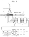
- FIG. 2 is a diagram illustrating a structure relating to a reception process performed by the measuring apparatus according to Example 1.
- the measuring apparatus includes a first delay and sum circuit 9, a signal extraction circuit 24, a second delay and sum circuit 27, a detection circuit 11, an image memory 12, and a CPU.
- the first delay and sum circuit 9 includes a delay adjustment circuit 7 and an add circuit 8.
- the signal extraction circuit 24 includes delay circuits 23a and 23b.
- the second delay and sum circuit includes a delay adjustment circuit 25 and an add circuit 26.
- the transmission beam 5 is reflected at a point P at a position of a distance r and is received by the transmission and reception element group 2.
- the reception signals 6 output from the individual transmission and reception elements are shifted in time according to a propagation distance of the reflected wave.
- each element of the transmission and reception element group 2 outputs the reception signal 6 of the reflected wave reflected from the point P with more delay as being apart outward from the center position of the transmission and reception element group 2.
- the delay adjustment circuit 7 receives ultrasonic echoes (reflected waves) superimposed from various directions, but a sum of the signals of the ultrasonic echoes from other points does not become a large signal component because they have nonuniform phases of the reception waves.
- a one-dimensional echo signal 13 of a raster scanning format is output as illustrated in FIG. 3 , so that the ultrasonic echo signal of a cross-sectional slice plane 14 may be obtained.
- the output echo signal is a signal having a frequency component of a transmission wave. Therefore, the echo signal is converted into envelope intensity by the detection circuit 11 and is temporarily stored in the image memory 12. Then, the CPU reads contents of the image memory 12 so that the ultrasonic echo image of the cross-sectional slice is displayed on an image display device (not shown).
- the detection circuit 11, the image memory 12, and the CPU constitute the image processing circuit.
- the add circuit 8 may also weight each input signal according to a position where the signal is obtained.
- the weighted adding process is called an apodizing process.
- the apodizing process has an effect of controlling a reception aperture and reducing influence of interference waves on the periphery.
- the weight may be fixed or variable according to reception time, depending on the purpose.
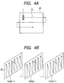
- FIG. 4A is a diagram illustrating an operation of moving the probe 1 along a route 21 in the elevation direction mechanically so as to obtain three-dimensional echo image data of a wide inspection area 20.
- a known mechanism may be used as a moving mechanism of the probe 1, so illustration and detailed description thereof are omitted.
- the probe 1 is moved as illustrated in FIG. 4A at a constant speed, so that the cross-sectional slice image is obtained repeatedly at individual positions on the route 21. Then, the obtained cross-sectional slice images are closely arranged, so that the three-dimensional echo image of the entire inspection area may be obtained.
- FIG. 4B illustrates scanning order of the output ultrasonic echo signal 22 when the cross-sectional slice planes are output in the order of ..., SL#(n-1), SL#(n), SL#(n+1), ..., while the probe 1 is moving continuously in the elevation direction.
- the echo signal 22 illustrated by the solid line of each ultrasonic wave transmission is calculated and output in the raster scanning order by the electronic scan inside each of the cross-sectional slice planes, and the cross-sectional slice planes are calculated and output at a constant period in the elevation direction.
- the echo signals at specific positions a, b and c in the cross-sectional slice planes are output at the constant period.
- the probe may move intermittently by a step and repeat method or may move continuously. If it moves continuously, the cross-sectional slice plane is not exactly perpendicular to the moving direction. However, for easy understanding, the cross-sectional slice plane is assumed herein to be perpendicular thereto.
- Example 1 the signal extraction circuit 24 including the delay circuits 23a and 23b, and the second delay and sum circuit 27 are added in the subsequent stage of the first delay and sum circuit 9, so that the two-dimensional delay and sum may be realized.
- the delay circuits 23a and 23b are cascaded, so that an output of the first delay and sum circuit 9 (the first add signal) is supplied to the delay circuit 23b, and an output of the delay circuit 23b is supplied to the delay circuit 23a.
- the delay times of the delay circuits 23a and 23b are each set to a value corresponding to a scanning period for one slice plane.
- the first delay and sum circuit 9 outputs an ultrasonic echo signal in the order illustrated in FIG. 4B .
- the signal extraction circuit 24 outputs in parallel the echo signals of the successive slice planes at the same position as illustrated by a, b and c of FIG. 4B . Therefore, if the delay adjustment circuit 25 and the add circuit 26 are set in the subsequent stage of the signal extraction circuit 24, the delay and sum in the elevation direction may be performed.
- the delay time of the delay circuits 23a and 23b is set to a constant value supposing that a scanning period for the slice plane (scan repeating pitch) is constant.
- a scanning period for the slice plane scan repeating pitch
- both the delay circuits 23a and 23b, and the delay adjustment circuit 25 are circuits for adjusting delay times. Therefore, the circuits may be integrated into one delay adjustment circuit, or a method of dividing the delay time may be changed variously. Such a modification does not change the spirit of the present invention.
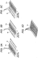
- FIGS. 5A, 5B, 5C, and 5D are diagrams illustrating a principle of the synthetic aperture method.
- Small oval figures 30 arranged in the diagrams indicate positions of the transmission and reception elements when the individual cross-sectional slice planes are scanned, and the point P indicates an arbitrary target point in the three-dimensional space.
- FIG. 5A illustrates a time point when the transmission and reception element group indicated by a rectangular figure 31a scans (n-1)th cross-sectional slice plane. A part of the ultrasonic wave beam emitted from the center part Sa propagates in the direction toward the point P, and a reflected wave thereof is received by the transmission and reception elements at the positions falling within the rectangular figure 31a.
- FIG. 5B illustrates a state in which the probe has moved to the n-th cross-sectional slice position.
- the transmission and reception element group falling within the rectangular figure 31b emits the ultrasonic wave beam from the center part Sb so that a part thereof also propagates in the direction toward the point P, and a reflected wave thereof is received by the transmission and reception element group in the position of the rectangular figure 31b.
- FIG. 5C illustrates a state in which the transmission and reception element group in the position of the rectangular figure 31c transmits and receives the ultrasonic wave with respect to the point P.
- the transmission and reception time point is different among the cross-sectional slice planes.
- the time period from the transmission to the reception is calculated based on the propagation distance and the sound velocity so as to adjust a signal reception time to be added to each reception element, to thereby add the signals from the same point P.
- FIG. 5D there may be obtained a result equivalent to the case where signals received by a virtual two-dimensional probe constituted of a transmission and reception element group falling within a rectangular figure 32 are calculated by the two-dimensional delay and sum.
- FIG. 6 is a diagram illustrating a principle of the present invention for solving the problem of cost.
- the target point P is in the plane of the cross-sectional slice SL#(n).
- the ultrasonic beam emitted at right angles from the center S0 of the transmission and reception element group is reflected at the point P and is received by the transmission and reception elements at a position R0.
- the probe moves to a position of the cross-sectional slice SL#(n+1), and emits the ultrasonic beam again from the position S1 corresponding to the position S0.
- the ultrasonic beam is emitted at right angles, and a part thereof also propagates in the direction toward the point P in the cross-sectional slice plane SL#(n), and an ultrasonic wave reflected at the point P is received at the point R1 corresponding to the point R0.
- the delay and sum of the above-mentioned synthetic aperture method may be realized by adding the reception signal at the point R0 and the reception signal at the point R1 after being adjusted in shift of reception time corresponding to propagation time from transmission via reflection at the point P to reception.
- an add signal obtained as a result of the one-dimensional delay and sum with the point P as the focal point may be completely the same to an add signal obtained as a result of the delay and sum with the point Q as the focal point. Therefore, it is understood that the two-dimensional delay and sum with respect to the point P may be realized by performing the one-dimensional delay and sum for each of the cross-sectional slice planes temporarily so as to determine the delay and sum signals of the point P and the point Q, and then performing an appropriate one-dimensional delay and sum in the elevation direction so as to add the delay and sum signals of the point P and the point Q.
- the measuring apparatus of Example 1 illustrated in FIG. 2 is an apparatus in which the principle described above is implemented by the real-time process circuit.
- the first add signal 10 output from the first delay and sum circuit 9 is supplied to the signal extraction circuit 24, the first add signals concerning the corresponding points in the three slice planes are extracted in parallel.
- the second delay and sum circuit 27 uses the signal output from the signal extraction circuit 24, the second delay and sum circuit 27 performs the delay and sum based on the synthetic aperture method, which is equivalent to performing the two-dimensional delay and sum as described above.
- the resolution in the elevation direction may be improved.
- N number of transmission and reception elements contribute to the two-dimensional delay and sum and there are M number of slice planes
- the delay and sum of MxN input signals is necessary in order to directly perform the two-dimensional delay and sum.
- the delay and sum of only M+N input signals is necessary in Example 1. Therefore, compared with the case where the two-dimensional delay and sum is performed directly, the circuit scale may be reduced significantly. Further, because the signal extraction circuit 24 and the second delay and sum circuit 27 operate in parallel as a pipeline, the real-time process may be performed in the same manner as in the case of only the one-dimensional delay and sum.
- FIG. 7 illustrates a structure relating to a reception process performed by a measuring apparatus of Example 2.
- the delay and sum is performed by the apodizing process in which a weight is added to each signal.
- the apodizing process is effective for performing optimal adjustment of an aperture size according to a focal point position of the delay and sum, or for reducing influence of an interference acoustic wave entering from other directions.
- weight multiplying circuits 41 and 42 are additionally provided in the preceding stages of the add circuit 8 of the first delay and sum circuit 9 and the add circuit 26 of the second delay and sum circuit 27, respectively, so that the apodizing process may be performed.
- the weight in this case may be fixed or may be variable according to signal reception time. Note that in Example 2, the apodizing process is performed in both the first delay and sum circuit 9 and the second delay and sum circuit 27, but the apodizing process may be performed only in either one of the circuits.
- FIG. 8 illustrates a structure relating to a reception process performed by a measuring apparatus of Example 3.
- Example 3 a plurality of second delay and sum circuits are provided, and the plurality of second delay and sum circuits have different focal point positions serving as a reference of the delay and sum (position in the elevation direction).
- the plurality of second delay and sum circuits set the focal point in different cross-sectional slice planes so as to perform the delay and sum process.
- the measuring apparatus of Example 3 includes four second delay and sum circuits constituted of delay adjustment circuits 25a, 25b, 25c, and 25d, and add circuits 26a, 26b, 26c, and 26d.
- the second delay and sum circuits are each supplied with the same signal from the signal extraction circuit 24.
- the outputs of the second delay and sum circuits are supplied to corresponding detection circuits 11a, 11b, 11c, and 11d.
- four cross-sectional slice planes SL#(4n), SL#(4n+1), SL#(4n+2), and SL#(4n+3) are calculated in parallel, and stored in the image memory 12.
- density of the cross-sectional slice planes output from the first delay and sum circuit 9 may be enhanced by four times, so that voxel density of the output three-dimensional echo image data in the elevation direction may be enhanced.
- the apodizing process may also be performed in Example 3.
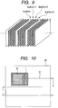
- FIG. 10 illustrates Example 4.
- a measuring apparatus of Example 4 is a photoacoustic mammography apparatus, which mechanically scans an object surface 20 along the route 21 by using a probe in which a two-dimensionally arranged sensor 51 for receiving the photoacoustic wave and the one-dimensional ultrasonic probe 1 are integrated.
- the photoacoustic mammography apparatus irradiates a pulse-like electromagnetic wave such as a pulse laser to an object and receives a photoacoustic wave induced inside the object by the two-dimensionally arranged sensor 51, so as to generate three-dimensional image data inside the object based on the reception signal.
- the two-dimensionally arranged sensor of the photoacoustic mammography apparatus receives acoustic waves in parallel in a short time after irradiating the electromagnetic wave. Accordingly, the two-dimensionally arranged sensor is capable of obtaining a high quality signal while moving at a constant speed. Meanwhile, the one-dimensional ultrasonic probe 1 receives echo ultrasonic waves similarly to Examples 1 to 3. Then, similarly to Examples 1, 2, and 3, the two-dimensional delay and sum process is performed on the reception signal, so that high resolution ultrasonic wave image data may be obtained. According to Example 4, the photoacoustic mammography apparatus which may obtain photoacoustic image data in the wide inspection area 20 and the high resolution ultrasonic wave image data at high speed may be formed with ease.
Description
- The present invention relates to a measuring apparatus which obtains information inside an object using an acoustic wave, and more particularly, to a measuring apparatus having a probe that is mechanically scanned.
- Conventionally, as an effective image diagnosis apparatus for early detection of breast cancer, there is known an x-ray mammography apparatus. Further, in recent years, there is developed a photoacoustic imaging method in which a pulse laser beam is irradiated onto a living body instead of an X-ray, so as to image a three-dimensional structure inside the living body based on a photoacoustic wave induced by thermal expansion of an optical absorber inside the living body. This apparatus has received attention as a new mammography apparatus that may easily diagnose a potential tumor such as an abnormal growth of new blood vessels.
- Such a mammography apparatus has a feature that an abnormal region which is difficult to detect by other apparatus may be detected as a clear image. However, for precise diagnosis of an early cancer, it is usually necessary to use both a mammography image and an ultrasonic echo image in combination. In view of this, for example, Japanese Patent Application Laid-Open No.
2006-102494 2008-161283 - In obtaining three-dimensional echo image data of a wide area with mechanically scanning the ultrasonic probe, it is most advantageous in speed and cost to move a one-dimensionally arranged probe in a direction perpendicular to the arrangement direction of elements or in a direction crossing the same (hereinafter, referred to as elevation direction) continuously while obtaining the echo image data. Using the one-dimensionally arranged probe, it is possible to reconstruct a cross-sectional slice image by electronic scanning in the arrangement direction and in an ultrasonic beam emitting direction. Therefore, there may be obtained three-dimensional image data of the entire mechanical scan area by stacking the cross-sectional slice images generated at individual positions in the elevation direction.
- However, this method has a problem that image resolution in the elevation direction significantly reduces as compared with image resolution in a slice plane. A first reason is that if the mechanical scan speed by the probe is decreased so as to reduce a pitch of obtaining the cross-sectional slice images, it may increase a physical load to the human object. Therefore, it is necessary to lower the pixel density in the elevation direction to some extent. In addition, a second reason is that effective angular aperture of the one-dimensionally arranged probe in the elevation direction is smaller than that in the arrangement direction, so that a reconstruction resolution in the elevation direction is deteriorated. If a two-dimensionally arranged probe is used, this problem may be alleviated to some extent. However, the number of transmission and reception elements increases, which leads to another problem that a necessary electric circuit scale increases, making it difficult to achieve the practical use of the apparatus in terms of cost.
- The
JP 2008-080093 A - The
US 5 186 175 A discloses an ultrasonic probe with transducers one-dimensionally arranged in long axis direction, wherein the probe is mechanically moved in a short axis direction to scan an object. - Further relevant prior art can be found in the
US 6 258 030 B1 and in L. Song et al.: "Fast 3-D dark-field reflection-mode photoacoustic microscopy in vivo with a 30-MHz ultrasound linear array", Journal of Biomedical Optics, vol. 13, no. 5, September 11, 2008, pages 054028-1 to 054028-5, XP040446892 , and in A. Aguirre et al.: "Feasibility Study of Three-dimensional Co-registered Ultrasound and Photoacoustic Imaging for Cancer Detection and Visualization", Photons Plus Ultrasound: Imaging and Sensing 2008 ; The Ninth Conference on Biomedical Thermoacoustics, Optoacoustics, and Acousto-Optics, Proceedings of SPIE, vol. 6856, 2008, pages 68562A-1 to 68562A-10, XP040433016, DOI:10.1117/12.775208 . - The
EP 0 087 318 A2 - An object of the present invention is to improve image resolution in the elevation direction with a simple structure without deteriorating a speed of obtaining image data in a measuring apparatus for obtaining image data while moving a probe in the elevation direction continuously.
- This is achieved by a measuring apparatus and a measuring method according to the appended claims.
- According to the present invention, image resolution in the elevation direction may be improved with a simple structure without deteriorating a speed of obtaining image data in the measuring apparatus for obtaining image data while moving the probe in the elevation direction continuously.
- Further features of the present invention will become apparent from the following description of exemplary
embodiments with reference to the attached drawings. -
-
FIG. 1 is a diagram illustrating a structure of a transmission process of a measuring apparatus according to Example 1; -
FIG. 2 is a diagram illustrating a structure of a reception process of the measuring apparatus according to Example 1; -
FIG. 3 is a diagram illustrating a signal in a cross-sectional slice plane obtained by electronic scan; -
FIGS. 4A and 4B are diagrams each illustrating a mechanical scan path and a signal obtained by the mechanical scan, respectively; -
FIGS. 5A, 5B, 5C, and 5D are explanatory diagrams of a synthetic aperture method; -
FIG. 6 is an explanatory diagram of a principle of the present invention; -
FIG. 7 is a diagram illustrating a structure of a reception process of a measuring apparatus according to Example 2; -
FIG. 8 is a diagram illustrating a structure of a reception process of a measuring apparatus according to Example 3; -
FIG. 9 is a diagram illustrating cross-sectional slice planes that are inserted in Example 3; and -
FIG. 10 is a diagram illustrating a probe of a measuring apparatus according to Example 4. - A measuring apparatus according to the present invention is an apparatus for obtaining information inside an object by using an acoustic wave (typically an ultrasonic wave), which is used as a medical ultrasonic diagnosis apparatus and the like, for example. The measuring apparatus of the present invention has a basic structure including a probe in which a plurality of elements for converting an acoustic wave into an electric signal are arranged, and a moving mechanism for moving the probe (for mechanical scan) along a surface of the object in an elevation direction. Note that the probe may be either a one-dimensionally arranged probe having a plurality of elements arranged in one-dimensional manner or a two-dimensionally arranged probe having a plurality of elements arranged in two-dimensional manner (in a matrix). However, for downsizing and cost reduction of the apparatus, it is preferable to use the one-dimensionally arranged probe. Usually, the elevation direction (second direction) is set so as to cross (perpendicular to or substantially perpendicular to) the arrangement direction of elements (first direction).
- In order to improve image resolution in the elevation direction, it is necessary to perform two-dimensional delay and sum by using input signals of successive cross-sectional slice planes. The two-dimensional delay and sum includes delay and sum in the arrangement direction of probe elements (first direction) and delay and sum in the elevation direction (second direction). However, the one-dimensionally arranged probe moves continuously so that individual slice planes have different transmission and reception timings of the acoustic wave. Therefore, it is necessary to regard the delay and sum in the arrangement direction as normal delay and sum and the delay and sum in the elevation direction as delay and sum based on the synthetic aperture method. Note that the delay and sum refers to a process of adjusting phases of a plurality of signals according to a propagation distance of the acoustic wave between a target point (focal point) and a reception point, and then summing (combining) the plurality of signals so as to obtain the signal indicating information of the target point.
- The present invention realizes the two-dimensional delay and sum by additionally including a relatively small circuit. According to the present invention, first, the one-dimensionally arranged probe is mechanically moved continuously along a surface of the object while the first delay and sum circuit repeats the one-dimensional delay and sum of the reception signal in the arrangement direction, so that the delay and sum is performed for each cross-sectional slice plane. The cross-sectional slice plane is a plane which is parallel to the arrangement direction of elements and crosses (is perpendicular to) the elevation direction. Thus, at individual positions along the elevation direction, delay and sum signals (first add signals) of a plurality of cross-sectional slice planes are calculated and delivered periodically. Then, the delay and sum signals delivered from the first delay and sum circuit are led to pass through one or more delay circuits so that the delay and sum signals at the corresponding positions of a plurality of successive cross-sectional slice planes are extracted in parallel. A delay time of the delay circuit may be set to a time corresponding to a scanning period for one slice plane. If two or more delay circuits are combined, the delay circuits are cascaded so that an output of a first delay circuit is supplied to an input of a second delay circuit. A plurality of delay and sum signals that are extracted in the manner as described above are delayed and summed in the elevation direction by the second delay and sum circuit, to thereby obtain a second add signal. The image processing circuit uses the second add signal so as to generate the image data.
- Note that an apparatus which moves the one-dimensional probe mechanically for scanning so as to generate three-dimensional image data is disclosed in Japanese Patent Application Laid-Open No.
H05-344975 - Japanese Patent Application Laid-Open No.
H05-146444 - The measuring apparatus of the present invention includes (1) a circuit for performing delay and sum of the reception signal, (2) a circuit for extracting delay and sum signals of a plurality of cross-sectional slice planes at the corresponding positions in parallel by using the delay circuit, and (3) a circuit for performing delay and sum of the plurality of delay and sum signal extracted in the elevation direction. With this structure, image resolution in the elevation direction may be improved with a relatively small circuit, without impairing real-time property.
- Note that the first delay and sum according to the present invention is a process for calculating the delay and sum signals in the individual cross-sectional slice planes. Therefore, if a two-dimensionally arranged probe having elements arranged in a two-dimensional manner is used, the first delay and sum circuit may be structured so as to calculate the delay and sum signals in one or more cross-sectional slice planes by the two-dimensional delay and sum. Alternatively, the two-dimensionally arranged probe may be used as a one-dimensionally arranged probe by driving only one column of elements in the two-dimensionally arranged probe so as to obtain one-dimensional reception signal.
- Further, the present invention may be similarly applied, not only to a reflected wave generated by reflection of the transmission ultrasonic wave, but also to a photoacoustic wave induced inside the object by a pulse-like electromagnetic wave radiated from a pulse laser. In this case, first, an electromagnetic wave source and a probe are moved continuously as one unit, so that the acoustic wave induced by the electromagnetic wave is received by the probe. In this manner, the three-dimensional photoacoustic image data may be generated by the same process as the case of the ultrasonic wave. In other words, the "acoustic wave" in the present invention is a concept which includes not only the reflected wave of the ultrasonic wave transmitted to the object (echo ultrasonic wave) but also the photoacoustic wave generated by expansion of an optical absorber inside the living body caused by the pulse light irradiated onto the object.
- According to the structure of the present invention described above, the three-dimensional ultrasonic wave image data of a wide area may be obtained by moving the probe for mechanical scanning. Further, with the addition of only a small and inexpensive circuit constituted of one or more delay circuits, image resolution in the elevation direction may be improved without impairing real-time property of the delay and sum process and the image reconstruction process. Therefore, with a relatively inexpensive apparatus using mechanical scan of the one-dimensionally arranged probe, there may be realized a measuring apparatus capable of obtaining high resolution and uniform three-dimensional ultrasonic wave image data at high speed. Further, the apparatus adopts the method of moving the small probe continuously, which makes it easy to use the apparatus together with a mammography apparatus which moves a sensor at a constant speed.
- With reference to
FIGS. 1 and2 , Example 1 of the present invention is described.FIG. 1 is a diagram illustrating a principle of a linear scanning method of transmitting anultrasonic beam 5 using a one-dimensionally arranged probe 1 (hereinafter, simply referred to as "probe"). The ultrasonic wave beam may also be emitted from one transmission and reception element of theprobe 1. However, usually, as illustrated inFIG. 1 , a plurality of transmission and reception elements are driven (hereinafter, a group of elements to be driven is referred to as "transmission andreception element group 2"), so as to emit a high intensity and high directivityultrasonic beam 5. In this case, atransmission control circuit 3 applies a pulse-like drive signal 4 to individual transmission and reception elements of the transmission andreception element group 2 at individual timings, so that each transmission and reception element is applied with the drive signal 4 a little earlier with increasing distance outward from the transmission center position. As a result, ultrasonic waves emitted from the individual transmission and reception elements propagate in a direction converging toward the center part as illustrated inFIG. 1 , so that a highintensity transmission beam 5 is formed as a whole so as to emit from the center part of the transmission andreception element group 2. - Immediately after emitting the pulse-like ultrasonic wave, the transmission and
reception element group 2 switches from the transmission operation to the reception operation, so as to receive the ultrasonic echo (reflected wave) that is reflected inside the object as described later. After finishing the reception, an adjacent transmission and reception element group is selected by a switch circuit (not shown), which performs the same transmission and reception operation as a new transmission andreception element group 2. In this way, the transmission andreception element group 2 is moved sequentially from the left end to the right end of theprobe 1 while the transmission and reception operation is repeated. Thus, thetransmission beam 5 may perform sequential electronic scan of the inside of the cross-sectional slice plane perpendicular to the surface of the probe. -
FIG. 2 is a diagram illustrating a structure relating to a reception process performed by the measuring apparatus according to Example 1. The measuring apparatus includes a first delay andsum circuit 9, asignal extraction circuit 24, a second delay andsum circuit 27, adetection circuit 11, animage memory 12, and a CPU. The first delay andsum circuit 9 includes adelay adjustment circuit 7 and anadd circuit 8. Thesignal extraction circuit 24 includesdelay circuits delay adjustment circuit 25 and anadd circuit 26. - First, with reference to
FIG. 2 , an operation of the measuring apparatus for receiving the reflected wave is described. It is supposed that thetransmission beam 5 is reflected at a point P at a position of a distance r and is received by the transmission andreception element group 2. Then, the reception signals 6 output from the individual transmission and reception elements are shifted in time according to a propagation distance of the reflected wave. In other words, each element of the transmission andreception element group 2 outputs thereception signal 6 of the reflected wave reflected from the point P with more delay as being apart outward from the center position of the transmission andreception element group 2. Therefore, with reference to the signal output from the transmission and reception element at the center position of the transmission andreception element group 2, delay times of the reception signals 6 output from the individual transmission and reception elements are adjusted by thedelay adjustment circuit 7, so that reflection signal components from the point P included in the reception signals of the individual transmission and reception elements are added by theadd circuit 8. Thus, a high intensity signal with a focal point of the point P may be obtained. The reception element receives ultrasonic echoes (reflected waves) superimposed from various directions, but a sum of the signals of the ultrasonic echoes from other points does not become a large signal component because they have nonuniform phases of the reception waves. - A time t at which the reflected wave from the point P of the distance r is received at the center position of the transmission and
reception element group 2 may be expressed as t=2r/c, where c denotes known sound velocity. Therefore, the distance r to the corresponding reflection position may be calculated based on the time t, and the signal delay time of each element may be calculated based on the calculated r. If the adjustment of delay times is performed appropriately by thedelay adjustment circuit 7 according to the corresponding distance r in real time together with the reception time t, high intensity one-dimensional reflection signal waveform may be formed with adjusted focus at every points. As a result, a reflection signal waveform of the one-dimensional area along the transmission beam path, that is, anultrasonic echo signal 10 may be formed. Therefore, if the transmission and reception of the ultrasonic beam is repeated by the above-mentioned electronic scanning method, a one-dimensional echo signal 13 of a raster scanning format is output as illustrated inFIG. 3 , so that the ultrasonic echo signal of across-sectional slice plane 14 may be obtained. - The output echo signal is a signal having a frequency component of a transmission wave. Therefore, the echo signal is converted into envelope intensity by the
detection circuit 11 and is temporarily stored in theimage memory 12. Then, the CPU reads contents of theimage memory 12 so that the ultrasonic echo image of the cross-sectional slice is displayed on an image display device (not shown). In other words, in this example, thedetection circuit 11, theimage memory 12, and the CPU constitute the image processing circuit. - Note that, when adding the input signals, the
add circuit 8 may also weight each input signal according to a position where the signal is obtained. The weighted adding process is called an apodizing process. The apodizing process has an effect of controlling a reception aperture and reducing influence of interference waves on the periphery. The weight may be fixed or variable according to reception time, depending on the purpose. -
FIG. 4A is a diagram illustrating an operation of moving theprobe 1 along aroute 21 in the elevation direction mechanically so as to obtain three-dimensional echo image data of awide inspection area 20. Note that a known mechanism may be used as a moving mechanism of theprobe 1, so illustration and detailed description thereof are omitted. Theprobe 1 is moved as illustrated inFIG. 4A at a constant speed, so that the cross-sectional slice image is obtained repeatedly at individual positions on theroute 21. Then, the obtained cross-sectional slice images are closely arranged, so that the three-dimensional echo image of the entire inspection area may be obtained. -
FIG. 4B illustrates scanning order of the outputultrasonic echo signal 22 when the cross-sectional slice planes are output in the order of ..., SL#(n-1), SL#(n), SL#(n+1), ..., while theprobe 1 is moving continuously in the elevation direction. As illustrated inFIG. 4B , theecho signal 22 illustrated by the solid line of each ultrasonic wave transmission is calculated and output in the raster scanning order by the electronic scan inside each of the cross-sectional slice planes, and the cross-sectional slice planes are calculated and output at a constant period in the elevation direction. As a result, the echo signals at specific positions a, b and c in the cross-sectional slice planes are output at the constant period. In this case, the probe may move intermittently by a step and repeat method or may move continuously. If it moves continuously, the cross-sectional slice plane is not exactly perpendicular to the moving direction. However, for easy understanding, the cross-sectional slice plane is assumed herein to be perpendicular thereto. - With reference to
FIG. 2 again, the two-dimensional delay and sum is described. In Example 1, thesignal extraction circuit 24 including thedelay circuits sum circuit 27 are added in the subsequent stage of the first delay andsum circuit 9, so that the two-dimensional delay and sum may be realized. Thedelay circuits delay circuit 23b, and an output of thedelay circuit 23b is supplied to thedelay circuit 23a. The delay times of thedelay circuits sum circuit 9 outputs an ultrasonic echo signal in the order illustrated inFIG. 4B . Accordingly, thesignal extraction circuit 24 outputs in parallel the echo signals of the successive slice planes at the same position as illustrated by a, b and c ofFIG. 4B . Therefore, if thedelay adjustment circuit 25 and theadd circuit 26 are set in the subsequent stage of thesignal extraction circuit 24, the delay and sum in the elevation direction may be performed. - In Example 1, the delay time of the
delay circuits delay circuits delay circuits delay adjustment circuit 25 are circuits for adjusting delay times. Therefore, the circuits may be integrated into one delay adjustment circuit, or a method of dividing the delay time may be changed variously. Such a modification does not change the spirit of the present invention. -
FIGS. 5A, 5B, 5C, and 5D are diagrams illustrating a principle of the synthetic aperture method. Small oval figures 30 arranged in the diagrams indicate positions of the transmission and reception elements when the individual cross-sectional slice planes are scanned, and the point P indicates an arbitrary target point in the three-dimensional space.FIG. 5A illustrates a time point when the transmission and reception element group indicated by a rectangular figure 31a scans (n-1)th cross-sectional slice plane. A part of the ultrasonic wave beam emitted from the center part Sa propagates in the direction toward the point P, and a reflected wave thereof is received by the transmission and reception elements at the positions falling within the rectangular figure 31a.FIG. 5B illustrates a state in which the probe has moved to the n-th cross-sectional slice position. The transmission and reception element group falling within the rectangular figure 31b emits the ultrasonic wave beam from the center part Sb so that a part thereof also propagates in the direction toward the point P, and a reflected wave thereof is received by the transmission and reception element group in the position of the rectangular figure 31b.FIG. 5C illustrates a state in which the transmission and reception element group in the position of the rectangular figure 31c transmits and receives the ultrasonic wave with respect to the point P. - The transmission and reception time point is different among the cross-sectional slice planes. Here, the time period from the transmission to the reception is calculated based on the propagation distance and the sound velocity so as to adjust a signal reception time to be added to each reception element, to thereby add the signals from the same point P. As a result, as illustrated in
FIG. 5D , there may be obtained a result equivalent to the case where signals received by a virtual two-dimensional probe constituted of a transmission and reception element group falling within a rectangular figure 32 are calculated by the two-dimensional delay and sum. In this manner, despite the use of the one-dimensional probe, there may be obtained echo image data having a resolution close to that in the case where a two-dimensional probe is used, which makes it possible, in particular, to improve a resolution in the elevation direction. This method of obtaining the performance equivalent to that in the case where reception signals of different ultrasonic wave transmission times are combined so as to increase the reception aperture substantially is a known technique as a synthetic aperture method. - Therefore, if all the reception signals of the transmission and reception elements in the past scanning are stored in the memory device, and if the reception signals two-dimensionally arranged are read out from the memory device simultaneously so as to perform the two-dimensional delay and sum, the resolution in the elevation direction may be improved. However, this method has a problem of apparatus cost because a large-capacity memory device and a circuit for performing delay and sum of many reception signals in real time are necessary.
-
FIG. 6 is a diagram illustrating a principle of the present invention for solving the problem of cost. For a simple description, it is supposed that the target point P is in the plane of the cross-sectional slice SL#(n). The ultrasonic beam emitted at right angles from the center S0 of the transmission and reception element group is reflected at the point P and is received by the transmission and reception elements at a position R0. Next, the probe moves to a position of the cross-sectional slice SL#(n+1), and emits the ultrasonic beam again from the position S1 corresponding to the position S0. The ultrasonic beam is emitted at right angles, and a part thereof also propagates in the direction toward the point P in the cross-sectional slice plane SL#(n), and an ultrasonic wave reflected at the point P is received at the point R1 corresponding to the point R0. The delay and sum of the above-mentioned synthetic aperture method may be realized by adding the reception signal at the point R0 and the reception signal at the point R1 after being adjusted in shift of reception time corresponding to propagation time from transmission via reflection at the point P to reception. - Next, consideration is given to a point Q having a distance from the point S1 in the vertical direction in the cross-sectional slice plane SL#(n+1) that is equal to the distance from the point S1 to the point P. In this case, a triangle having the points S1, P, and R1 at each corner is apparently congruence with a triangle having the points S1, Q, and R1 at each corner. Therefore, the time of propagation from the point S1 via the point P to the point R1 is the same as the time of propagation from the point S1 via the point Q to the point R1. This relationship applies not only to the transmission and reception element at the position of R1 but also to other reception elements in the same transmission and reception element group. Therefore, at the position of the cross-sectional slice plane SL#(n+1), an add signal obtained as a result of the one-dimensional delay and sum with the point P as the focal point may be completely the same to an add signal obtained as a result of the delay and sum with the point Q as the focal point. Therefore, it is understood that the two-dimensional delay and sum with respect to the point P may be realized by performing the one-dimensional delay and sum for each of the cross-sectional slice planes temporarily so as to determine the delay and sum signals of the point P and the point Q, and then performing an appropriate one-dimensional delay and sum in the elevation direction so as to add the delay and sum signals of the point P and the point Q.
- The measuring apparatus of Example 1 illustrated in
FIG. 2 is an apparatus in which the principle described above is implemented by the real-time process circuit. When thefirst add signal 10 output from the first delay andsum circuit 9 is supplied to thesignal extraction circuit 24, the first add signals concerning the corresponding points in the three slice planes are extracted in parallel. Using the signal output from thesignal extraction circuit 24, the second delay andsum circuit 27 performs the delay and sum based on the synthetic aperture method, which is equivalent to performing the two-dimensional delay and sum as described above. - As a result, compared with the case where only the one-dimensional delay and sum is simply performed, the resolution in the elevation direction may be improved. When N number of transmission and reception elements contribute to the two-dimensional delay and sum and there are M number of slice planes, the delay and sum of MxN input signals is necessary in order to directly perform the two-dimensional delay and sum. In contrast, the delay and sum of only M+N input signals is necessary in Example 1. Therefore, compared with the case where the two-dimensional delay and sum is performed directly, the circuit scale may be reduced significantly. Further, because the
signal extraction circuit 24 and the second delay andsum circuit 27 operate in parallel as a pipeline, the real-time process may be performed in the same manner as in the case of only the one-dimensional delay and sum. -
FIG. 7 illustrates a structure relating to a reception process performed by a measuring apparatus of Example 2. In Example 2, the delay and sum is performed by the apodizing process in which a weight is added to each signal. The apodizing process is effective for performing optimal adjustment of an aperture size according to a focal point position of the delay and sum, or for reducing influence of an interference acoustic wave entering from other directions. In Example 2,weight multiplying circuits add circuit 8 of the first delay andsum circuit 9 and theadd circuit 26 of the second delay andsum circuit 27, respectively, so that the apodizing process may be performed. The weight in this case may be fixed or may be variable according to signal reception time. Note that in Example 2, the apodizing process is performed in both the first delay andsum circuit 9 and the second delay andsum circuit 27, but the apodizing process may be performed only in either one of the circuits. -
FIG. 8 illustrates a structure relating to a reception process performed by a measuring apparatus of Example 3. In Example 3, a plurality of second delay and sum circuits are provided, and the plurality of second delay and sum circuits have different focal point positions serving as a reference of the delay and sum (position in the elevation direction). - In
FIG. 6 , it is supposed that the focal point P exists in the cross-sectional slice plane obtained by the mechanical scan for a simple description. However, the point P may be at any position in principle. Therefore, in Example 3, the plurality of second delay and sum circuits set the focal point in different cross-sectional slice planes so as to perform the delay and sum process. Specifically, the measuring apparatus of Example 3 includes four second delay and sum circuits constituted ofdelay adjustment circuits circuits 26a, 26b, 26c, and 26d. The second delay and sum circuits are each supplied with the same signal from thesignal extraction circuit 24. In addition, the outputs of the second delay and sum circuits are supplied tocorresponding detection circuits 11a, 11b, 11c, and 11d. With this structure, four cross-sectional slice planes SL#(4n), SL#(4n+1), SL#(4n+2), and SL#(4n+3) are calculated in parallel, and stored in theimage memory 12. According to Example 3, as illustrated inFIG. 9 , density of the cross-sectional slice planes output from the first delay andsum circuit 9 may be enhanced by four times, so that voxel density of the output three-dimensional echo image data in the elevation direction may be enhanced. Note that the apodizing process may also be performed in Example 3. -
FIG. 10 illustrates Example 4. A measuring apparatus of Example 4 is a photoacoustic mammography apparatus, which mechanically scans anobject surface 20 along theroute 21 by using a probe in which a two-dimensionally arrangedsensor 51 for receiving the photoacoustic wave and the one-dimensionalultrasonic probe 1 are integrated. The photoacoustic mammography apparatus irradiates a pulse-like electromagnetic wave such as a pulse laser to an object and receives a photoacoustic wave induced inside the object by the two-dimensionally arrangedsensor 51, so as to generate three-dimensional image data inside the object based on the reception signal. The two-dimensionally arranged sensor of the photoacoustic mammography apparatus receives acoustic waves in parallel in a short time after irradiating the electromagnetic wave. Accordingly, the two-dimensionally arranged sensor is capable of obtaining a high quality signal while moving at a constant speed. Meanwhile, the one-dimensionalultrasonic probe 1 receives echo ultrasonic waves similarly to Examples 1 to 3. Then, similarly to Examples 1, 2, and 3, the two-dimensional delay and sum process is performed on the reception signal, so that high resolution ultrasonic wave image data may be obtained. According to Example 4, the photoacoustic mammography apparatus which may obtain photoacoustic image data in thewide inspection area 20 and the high resolution ultrasonic wave image data at high speed may be formed with ease.
Claims (14)
- A measuring apparatus, comprising:a probe (1) having a plurality of elements each converting an acoustic wave into an electric signal, the plurality of elements being arranged at least in a first direction;a moving mechanism for moving the probe in a second direction crossing the first direction;a first delay and sum circuit (9) for performing delay and sum in the first direction using a plurality of the electric signals obtained by the plurality of elements at individual positions along the second direction, so as to obtain a plurality of first add signals corresponding to a plurality of target points within individual cross-sectional planes in an object, wherein the cross-sectional planes are arranged successively along the second direction;a signal extraction circuit (24) for letting an output from the first delay and sum circuit to pass through first and second delay circuits (23a, 23b), so as to output in parallel a plurality of the first add signals, wherein the first add signals output in parallel from the signal extraction circuit correspond to a same position within individual cross-sectional planes;a second delay and sum circuit (27) for performing delay and sum using the plurality of first add signals output from the signal extraction circuit, so as to obtain second add signals; andan image processing circuit for generating image data inside the object by using a plurality of the second add signals corresponding to a plurality of individual target points,characterized in thatthe first and second delay circuits (23a, 23b) are cascaded, so that the output of the first delay and sum circuit (9) is supplied to the second delay circuit (23b) and an output of the second delay circuit (23b) is supplied to the first delay circuit (23a),wherein delay times of the first and second delay circuits (23a, 23b) are each set to a value corresponding to a scanning period of the probe (1) for one cross-sectional plane.
- A measuring apparatus according to claim 1, wherein the plurality of the electric signals are obtained by electronic scan.
- A measuring apparatus according to claim 1 or 2, further comprising a plurality of the second delay and sum circuits (27), and the plurality of the second delay and sum circuits have different target points serving as a reference of the delay and sum.
- A measuring apparatus according to any one of claims 1 to 3, wherein at least one or both of the first delay and sum circuit (9) and the second delay and sum circuit (27) perform the delay and sum with a weight assigned to each signal according to a position where the signal is obtained.
- A measuring apparatus according to any one of claims 1 to 4, wherein the acoustic wave is a reflected wave generated when the acoustic wave transmitted from the element is reflected inside the object.
- A measuring apparatus according to any one of claims 1 to 4, wherein the acoustic wave is a photoacoustic wave induced inside the object irradiated with an electromagnetic wave.
- A measuring apparatus according to any one of claims 1 to 6, wherein the moving mechanism continuously moves the probe (1) in the second direction.
- A measuring method, comprising:moving a probe (1) in a second direction crossing a first direction, wherein the probe (1) has a plurality of elements each converting an acoustic wave into an electric signal, the plurality of elements being arranged at least in the first direction;performing first delay and sum in the first direction using a plurality of the electric signals obtained by the plurality of elements at individual positions along the second direction, so as to obtain a plurality of first add signals corresponding to a plurality of target points within individual cross-sectional planes in an object, wherein the cross-sectional planes are arranged successively along the second direction;letting an output from the first delay and sum to pass through first and second delay circuits (23a, 23b), so as to output in parallel a plurality of the first add signals, wherein the first add signals output in parallel correspond to a same position within individual cross-sectional planes;performing second delay and sum using the plurality of output first add signals, so as to obtain second add signals; andgenerating image data inside the object by using a plurality of the second add signals corresponding to a plurality of individual target points,characterized in thatthe first and second delay circuits (23a, 23b) are cascaded, so that the output of the first delay and sum is supplied to the second delay circuit (23b) and an output of the second delay circuit (23b) is supplied to the first delay circuit (23a),wherein delay times of the first and second delay circuits (23a, 23b) are each set to a value corresponding to a scanning period of the probe (1) for one cross-sectional plane.
- A measuring method according to claim 8, wherein the plurality of electric signals are obtained by electronic scan.
- A measuring method according to claim 8 or 9, wherein the second delay and sum is performed several times using different target points serving as a reference of the delay and sum.
- A measuring method according to any one of claims 8 to 10, wherein at least one or both of the first delay and sum and the second delay and sum is/are performed with a weight assigned to each signal according to a position where the signal is obtained.
- A measuring method according to any one of claims 8 to 11, wherein the acoustic wave is a reflected wave generated when the acoustic wave transmitted from the element is reflected inside the object.
- A measuring method according to any one of claims 8 to 11, wherein the acoustic wave is a photoacoustic wave induced inside the object irradiated with an electromagnetic wave.
- A measuring method according to any one of claims 8 to 13, wherein the probe is moved continuously in the second direction.
Applications Claiming Priority (2)
| Application Number | Priority Date | Filing Date | Title |
|---|---|---|---|
| JP2009124888A JP5393256B2 (en) | 2009-05-25 | 2009-05-25 | Ultrasonic device |
| PCT/JP2010/057916 WO2010137451A2 (en) | 2009-05-25 | 2010-04-28 | Measuring apparatus |
Publications (2)
| Publication Number | Publication Date |
|---|---|
| EP2435849A2 EP2435849A2 (en) | 2012-04-04 |
| EP2435849B1 true EP2435849B1 (en) | 2017-08-02 |
Family
ID=43223184
Family Applications (1)
| Application Number | Title | Priority Date | Filing Date |
|---|---|---|---|
| EP10722791.0A Active EP2435849B1 (en) | 2009-05-25 | 2010-04-28 | Measuring apparatus |
Country Status (5)
| Country | Link |
|---|---|
| US (1) | US9116225B2 (en) |
| EP (1) | EP2435849B1 (en) |
| JP (1) | JP5393256B2 (en) |
| CN (1) | CN102449498B (en) |
| WO (1) | WO2010137451A2 (en) |
Families Citing this family (27)
| Publication number | Priority date | Publication date | Assignee | Title |
|---|---|---|---|---|
| DK2233149T3 (en) * | 2007-10-16 | 2016-05-17 | Zymogenetics Inc | COMBINATION OF TRANSMEMBRANAKTIVATOR AND CALCIUM MODULATOR AND cyclophilin-LIGAND INTERAKTOR (TACI) AND ANTI-CD20 MEANS FOR TREATMENT OF AUTO-IMMUNE DISEASE |
| JP5483905B2 (en) | 2009-03-03 | 2014-05-07 | キヤノン株式会社 | Ultrasonic device |
| JP5645421B2 (en) | 2010-02-23 | 2014-12-24 | キヤノン株式会社 | Ultrasonic imaging apparatus and delay control method |
| JP5424933B2 (en) * | 2010-02-23 | 2014-02-26 | キヤノン株式会社 | Biological information processing device |
| JP5637725B2 (en) | 2010-04-12 | 2014-12-10 | キヤノン株式会社 | Acoustic wave imaging device |
| JP5389749B2 (en) * | 2010-06-24 | 2014-01-15 | 富士フイルム株式会社 | Biological information imaging apparatus and method |
| JP5721462B2 (en) * | 2011-02-09 | 2015-05-20 | キヤノン株式会社 | Subject information acquisition device |
| JP5850640B2 (en) | 2011-05-10 | 2016-02-03 | キヤノン株式会社 | Subject information acquisition apparatus and subject information acquisition method |
| JP2012235832A (en) | 2011-05-10 | 2012-12-06 | Canon Inc | Object information acquiring apparatus |
| JP5847490B2 (en) | 2011-08-25 | 2016-01-20 | キヤノン株式会社 | Subject information acquisition device |
| JP2013215259A (en) * | 2012-04-05 | 2013-10-24 | Canon Inc | Subject information acquisition apparatus |
| JP6039305B2 (en) | 2012-08-23 | 2016-12-07 | キヤノン株式会社 | Subject information acquisition apparatus, information processing apparatus, and subject information acquisition method |
| CN103257349B (en) * | 2012-08-24 | 2015-04-29 | 北京化工大学 | Synthetic aperture ultrasonic imaging system for calculating delay time based on non-linear correlation |
| JP6508867B2 (en) | 2013-03-29 | 2019-05-08 | キヤノン株式会社 | Object information acquisition apparatus and control method therefor |
| JP6253323B2 (en) | 2013-09-26 | 2017-12-27 | キヤノン株式会社 | Subject information acquisition apparatus and control method thereof |
| JP6285241B2 (en) * | 2014-03-26 | 2018-02-28 | 富士フイルム株式会社 | Acoustic wave processing device, signal processing method and program for acoustic wave processing device |
| US10349917B2 (en) * | 2014-06-11 | 2019-07-16 | The Johns Hopkins University | Synthetic aperture ultrasound system |
| CN104569991A (en) * | 2015-02-06 | 2015-04-29 | 中国安全生产科学研究院 | Sonar detection device for three-dimensional space of mine gob |
| JP2017086172A (en) * | 2015-11-02 | 2017-05-25 | キヤノン株式会社 | Subject information acquisition device and control method thereof |
| JP6925815B2 (en) * | 2016-03-07 | 2021-08-25 | キヤノンメディカルシステムズ株式会社 | Ultrasonic diagnostic equipment |
| US11103214B2 (en) | 2016-03-07 | 2021-08-31 | Toshiba Medical Systems Corporation | Ultrasonic diagnostic apparatus using synthetic and moving aperture synthesis |
| US11263801B2 (en) | 2017-03-31 | 2022-03-01 | Schlumberger Technology Corporation | Smooth surface wrapping of features in an imaged volume |
| JP7195759B2 (en) | 2018-04-20 | 2022-12-26 | キヤノン株式会社 | Photoacoustic device and object information acquisition method |
| JP7099162B2 (en) * | 2018-08-10 | 2022-07-12 | コニカミノルタ株式会社 | Ultrasonic signal processing method and ultrasonic signal processing device |
| CN112650707A (en) * | 2019-10-10 | 2021-04-13 | 上海科技大学 | Multichannel photoacoustic signal delay device, multichannel photoacoustic signal delay system, signal processing method, terminal and medium |
| JP2021065449A (en) * | 2019-10-24 | 2021-04-30 | 株式会社リコー | Measuring device, beam measuring method and beam measuring program |
| CN111035368B (en) * | 2020-01-07 | 2022-12-13 | 上海科技大学 | Single-channel real-time photoacoustic tomography imaging system and method |
Citations (1)
| Publication number | Priority date | Publication date | Assignee | Title |
|---|---|---|---|---|
| EP0087318A2 (en) * | 1982-02-24 | 1983-08-31 | Kabushiki Kaisha Toshiba | Ultrasonic diagnostic apparatus |
Family Cites Families (23)
| Publication number | Priority date | Publication date | Assignee | Title |
|---|---|---|---|---|
| FR2460489A1 (en) * | 1979-07-04 | 1981-01-23 | Labo Electronique Physique | CIRCUIT FOR PROCESSING RECEPTION SIGNALS OF A ULTRA-SOUND TRANSDUCER MOSAIC USED IN B-TYPE ECHOGRAPHY |
| JP3090718B2 (en) * | 1990-07-11 | 2000-09-25 | 株式会社東芝 | Ultrasound diagnostic equipment |
| JP3329485B2 (en) | 1992-06-15 | 2002-09-30 | 株式会社東芝 | Ultrasound diagnostic equipment |
| JP3210442B2 (en) | 1992-10-14 | 2001-09-17 | フクダ電子株式会社 | Ultrasonic probe and conversion connector |
| JP2723464B2 (en) | 1994-03-02 | 1998-03-09 | アロカ株式会社 | Ultrasound diagnostic equipment |
| JP2000254120A (en) * | 1999-03-11 | 2000-09-19 | Toshiba Corp | Three-dimensional ultrasonograph |
| JP3685993B2 (en) * | 2000-12-01 | 2005-08-24 | 松下電器産業株式会社 | Ultrasonic diagnostic equipment |
| JP4643153B2 (en) * | 2004-02-06 | 2011-03-02 | 株式会社東芝 | Non-invasive biological information imaging device |
| US20060074287A1 (en) | 2004-09-30 | 2006-04-06 | General Electric Company | Systems, methods and apparatus for dual mammography image detection |
| JP2006158799A (en) | 2004-12-10 | 2006-06-22 | Ge Medical Systems Global Technology Co Llc | Ultrasonic imaging apparatus |
| BRPI0713454A8 (en) | 2006-06-23 | 2015-10-06 | Koninklijke Philips Electronics Nv | IMAGE GENERATION SYSTEM, AND METHOD FOR GENERATING A COMBINED PHOTO-ACOUSTIC AND ULTRASOUND IMAGE OF A SAMPLE |
| JP5084270B2 (en) | 2006-08-31 | 2012-11-28 | 日本電波工業株式会社 | Ultrasonic probe |
| JP5052123B2 (en) | 2006-12-27 | 2012-10-17 | 富士フイルム株式会社 | Medical imaging system and method |
| EP2002784B1 (en) | 2007-06-11 | 2018-07-11 | Canon Kabushiki Kaisha | Intravital-information imaging apparatus |
| US20090005685A1 (en) | 2007-06-29 | 2009-01-01 | Canon Kabushiki Kaisha | Ultrasonic probe and inspection apparatus equipped with the ultrasonic probe |
| JP2009028366A (en) * | 2007-07-27 | 2009-02-12 | Toshiba Corp | Ultrasonic diagnostic apparatus |
| JP5294687B2 (en) | 2008-05-02 | 2013-09-18 | キヤノン株式会社 | Ultrasonic measuring device and control method thereof |
| JP5495607B2 (en) | 2008-05-27 | 2014-05-21 | キヤノン株式会社 | Ultrasonic diagnostic equipment |
| JP5511201B2 (en) | 2008-07-31 | 2014-06-04 | キヤノン株式会社 | SIGNAL PROCESSING DEVICE, ULTRASONIC DEVICE, SIGNAL PROCESSING DEVICE CONTROL METHOD, AND ULTRASONIC DEVICE CONTROL METHOD |
| JP5419404B2 (en) | 2008-09-04 | 2014-02-19 | キヤノン株式会社 | Photoacoustic device |
| JP5483905B2 (en) | 2009-03-03 | 2014-05-07 | キヤノン株式会社 | Ultrasonic device |
| JP5424933B2 (en) | 2010-02-23 | 2014-02-26 | キヤノン株式会社 | Biological information processing device |
| JP5448918B2 (en) | 2010-02-24 | 2014-03-19 | キヤノン株式会社 | Biological information processing device |
-
2009
- 2009-05-25 JP JP2009124888A patent/JP5393256B2/en active Active
-
2010
- 2010-04-28 WO PCT/JP2010/057916 patent/WO2010137451A2/en active Application Filing
- 2010-04-28 EP EP10722791.0A patent/EP2435849B1/en active Active
- 2010-04-28 CN CN201080022646.XA patent/CN102449498B/en active Active
- 2010-04-28 US US13/266,981 patent/US9116225B2/en active Active
Patent Citations (1)
| Publication number | Priority date | Publication date | Assignee | Title |
|---|---|---|---|---|
| EP0087318A2 (en) * | 1982-02-24 | 1983-08-31 | Kabushiki Kaisha Toshiba | Ultrasonic diagnostic apparatus |
Also Published As
| Publication number | Publication date |
|---|---|
| EP2435849A2 (en) | 2012-04-04 |
| US9116225B2 (en) | 2015-08-25 |
| CN102449498B (en) | 2014-12-17 |
| JP2010269046A (en) | 2010-12-02 |
| WO2010137451A2 (en) | 2010-12-02 |
| US20120044785A1 (en) | 2012-02-23 |
| JP5393256B2 (en) | 2014-01-22 |
| CN102449498A (en) | 2012-05-09 |
| WO2010137451A3 (en) | 2011-03-17 |
Similar Documents
| Publication | Publication Date | Title |
|---|---|---|
| EP2435849B1 (en) | Measuring apparatus | |
| US9247923B2 (en) | Received data processing apparatus of photoacoustic tomography | |
| US8241218B2 (en) | Ultrasonic diagnostic apparatus | |
| US9364152B2 (en) | Object information acquiring apparatus | |
| US20110208057A1 (en) | Subject information processing apparatus | |
| US8905931B2 (en) | Subject information processing apparatus | |
| JP5946427B2 (en) | Ultrasonic inspection apparatus, ultrasonic inspection method, program, and recording medium | |
| US11439368B2 (en) | Acoustic wave processing device, signal processing method for acoustic wave processing device, and program | |
| US20150196280A1 (en) | Ultrasound diagnostic apparatus, ultrasound image generating method, and recording medium | |
| US20120259225A1 (en) | Ultrasound diagnostic apparatus and ultrasound image producing method | |
| JP2009240700A (en) | Ultrasonic diagnostic device | |
| JP2009240667A (en) | Ultrasonic imaging apparatus and ultrasonic imaging method | |
| JP2016096914A (en) | Subject information acquisition device | |
| US20130072798A1 (en) | Object information acquiring apparatus and control method thereof | |
| JP2009061086A (en) | Ultrasonic diagnostic system, image processing method, and program | |
| JP6000678B2 (en) | Subject information acquisition apparatus and subject information acquisition method | |
| JP5281107B2 (en) | Ultrasonic diagnostic apparatus and ultrasonic image generation method | |
| US20180140280A1 (en) | Ultrasound signal processing device, ultrasound diagnostic apparatus, and ultrasound signal processing method | |
| JP5829198B2 (en) | Ultrasonic inspection apparatus, signal processing method and program for ultrasonic inspection apparatus | |
| JPH08289891A (en) | Ultrasonic diagnostic device | |
| JP5709958B2 (en) | apparatus | |
| JP2010110642A (en) | Ultrasonic diagnostic apparatus | |
| JP2000316854A (en) | Ultrasonic device | |
| JP6253699B2 (en) | DATA PROCESSING METHOD, DATA PROCESSING DEVICE, METHOD, AND DEVICE | |
| JP2023112108A (en) | Ultrasonic diagnostic apparatus |
Legal Events
| Date | Code | Title | Description |
|---|---|---|---|
| PUAI | Public reference made under article 153(3) epc to a published international application that has entered the european phase |
Free format text: ORIGINAL CODE: 0009012 |
|
| 17P | Request for examination filed |
Effective date: 20111227 |
|
| AK | Designated contracting states |
Kind code of ref document: A2 Designated state(s): AT BE BG CH CY CZ DE DK EE ES FI FR GB GR HR HU IE IS IT LI LT LU LV MC MK MT NL NO PL PT RO SE SI SK SM TR |
|
| DAX | Request for extension of the european patent (deleted) | ||
| 17Q | First examination report despatched |
Effective date: 20121108 |
|
| GRAP | Despatch of communication of intention to grant a patent |
Free format text: ORIGINAL CODE: EPIDOSNIGR1 |
|
| RIC1 | Information provided on ipc code assigned before grant |
Ipc: G01S 7/52 20060101AFI20160831BHEP Ipc: A61B 8/08 20060101ALN20160831BHEP Ipc: G10K 11/35 20060101ALI20160831BHEP Ipc: G10K 11/34 20060101ALI20160831BHEP Ipc: G01S 15/89 20060101ALI20160831BHEP |
|
| RIC1 | Information provided on ipc code assigned before grant |
Ipc: G01S 15/89 20060101ALI20160905BHEP Ipc: A61B 8/08 20060101ALN20160905BHEP Ipc: G01S 7/52 20060101AFI20160905BHEP Ipc: G10K 11/34 20060101ALI20160905BHEP Ipc: G10K 11/35 20060101ALI20160905BHEP |
|
| INTG | Intention to grant announced |
Effective date: 20160920 |
|
| GRAJ | Information related to disapproval of communication of intention to grant by the applicant or resumption of examination proceedings by the epo deleted |
Free format text: ORIGINAL CODE: EPIDOSDIGR1 |
|
| GRAP | Despatch of communication of intention to grant a patent |
Free format text: ORIGINAL CODE: EPIDOSNIGR1 |
|
| INTC | Intention to grant announced (deleted) | ||
| INTG | Intention to grant announced |
Effective date: 20170210 |
|
| RIC1 | Information provided on ipc code assigned before grant |
Ipc: G01S 7/52 20060101AFI20170131BHEP Ipc: G10K 11/35 20060101ALI20170131BHEP Ipc: G10K 11/34 20060101ALI20170131BHEP Ipc: G01S 15/89 20060101ALI20170131BHEP Ipc: A61B 8/08 20060101ALN20170131BHEP |
|
| GRAS | Grant fee paid |
Free format text: ORIGINAL CODE: EPIDOSNIGR3 |
|
| GRAA | (expected) grant |
Free format text: ORIGINAL CODE: 0009210 |
|
| AK | Designated contracting states |
Kind code of ref document: B1 Designated state(s): AT BE BG CH CY CZ DE DK EE ES FI FR GB GR HR HU IE IS IT LI LT LU LV MC MK MT NL NO PL PT RO SE SI SK SM TR |
|
| REG | Reference to a national code |
Ref country code: GB Ref legal event code: FG4D |
|
| REG | Reference to a national code |
Ref country code: CH Ref legal event code: EP Ref country code: AT Ref legal event code: REF Ref document number: 915070 Country of ref document: AT Kind code of ref document: T Effective date: 20170815 |
|
| REG | Reference to a national code |
Ref country code: IE Ref legal event code: FG4D |
|
| REG | Reference to a national code |
Ref country code: DE Ref legal event code: R096 Ref document number: 602010044053 Country of ref document: DE |
|
| REG | Reference to a national code |
Ref country code: NL Ref legal event code: MP Effective date: 20170802 |
|
| REG | Reference to a national code |
Ref country code: AT Ref legal event code: MK05 Ref document number: 915070 Country of ref document: AT Kind code of ref document: T Effective date: 20170802 |
|
| REG | Reference to a national code |
Ref country code: LT Ref legal event code: MG4D |
|
| PG25 | Lapsed in a contracting state [announced via postgrant information from national office to epo] |
Ref country code: NO Free format text: LAPSE BECAUSE OF FAILURE TO SUBMIT A TRANSLATION OF THE DESCRIPTION OR TO PAY THE FEE WITHIN THE PRESCRIBED TIME-LIMIT Effective date: 20171102 Ref country code: SE Free format text: LAPSE BECAUSE OF FAILURE TO SUBMIT A TRANSLATION OF THE DESCRIPTION OR TO PAY THE FEE WITHIN THE PRESCRIBED TIME-LIMIT Effective date: 20170802 Ref country code: AT Free format text: LAPSE BECAUSE OF FAILURE TO SUBMIT A TRANSLATION OF THE DESCRIPTION OR TO PAY THE FEE WITHIN THE PRESCRIBED TIME-LIMIT Effective date: 20170802 Ref country code: FI Free format text: LAPSE BECAUSE OF FAILURE TO SUBMIT A TRANSLATION OF THE DESCRIPTION OR TO PAY THE FEE WITHIN THE PRESCRIBED TIME-LIMIT Effective date: 20170802 Ref country code: HR Free format text: LAPSE BECAUSE OF FAILURE TO SUBMIT A TRANSLATION OF THE DESCRIPTION OR TO PAY THE FEE WITHIN THE PRESCRIBED TIME-LIMIT Effective date: 20170802 Ref country code: LT Free format text: LAPSE BECAUSE OF FAILURE TO SUBMIT A TRANSLATION OF THE DESCRIPTION OR TO PAY THE FEE WITHIN THE PRESCRIBED TIME-LIMIT Effective date: 20170802 Ref country code: NL Free format text: LAPSE BECAUSE OF FAILURE TO SUBMIT A TRANSLATION OF THE DESCRIPTION OR TO PAY THE FEE WITHIN THE PRESCRIBED TIME-LIMIT Effective date: 20170802 |
|
| PG25 | Lapsed in a contracting state [announced via postgrant information from national office to epo] |
Ref country code: GR Free format text: LAPSE BECAUSE OF FAILURE TO SUBMIT A TRANSLATION OF THE DESCRIPTION OR TO PAY THE FEE WITHIN THE PRESCRIBED TIME-LIMIT Effective date: 20171103 Ref country code: PL Free format text: LAPSE BECAUSE OF FAILURE TO SUBMIT A TRANSLATION OF THE DESCRIPTION OR TO PAY THE FEE WITHIN THE PRESCRIBED TIME-LIMIT Effective date: 20170802 Ref country code: IS Free format text: LAPSE BECAUSE OF FAILURE TO SUBMIT A TRANSLATION OF THE DESCRIPTION OR TO PAY THE FEE WITHIN THE PRESCRIBED TIME-LIMIT Effective date: 20171202 Ref country code: ES Free format text: LAPSE BECAUSE OF FAILURE TO SUBMIT A TRANSLATION OF THE DESCRIPTION OR TO PAY THE FEE WITHIN THE PRESCRIBED TIME-LIMIT Effective date: 20170802 Ref country code: BG Free format text: LAPSE BECAUSE OF FAILURE TO SUBMIT A TRANSLATION OF THE DESCRIPTION OR TO PAY THE FEE WITHIN THE PRESCRIBED TIME-LIMIT Effective date: 20171102 Ref country code: LV Free format text: LAPSE BECAUSE OF FAILURE TO SUBMIT A TRANSLATION OF THE DESCRIPTION OR TO PAY THE FEE WITHIN THE PRESCRIBED TIME-LIMIT Effective date: 20170802 |
|
| PG25 | Lapsed in a contracting state [announced via postgrant information from national office to epo] |
Ref country code: CZ Free format text: LAPSE BECAUSE OF FAILURE TO SUBMIT A TRANSLATION OF THE DESCRIPTION OR TO PAY THE FEE WITHIN THE PRESCRIBED TIME-LIMIT Effective date: 20170802 Ref country code: RO Free format text: LAPSE BECAUSE OF FAILURE TO SUBMIT A TRANSLATION OF THE DESCRIPTION OR TO PAY THE FEE WITHIN THE PRESCRIBED TIME-LIMIT Effective date: 20170802 Ref country code: DK Free format text: LAPSE BECAUSE OF FAILURE TO SUBMIT A TRANSLATION OF THE DESCRIPTION OR TO PAY THE FEE WITHIN THE PRESCRIBED TIME-LIMIT Effective date: 20170802 |
|
| REG | Reference to a national code |
Ref country code: DE Ref legal event code: R097 Ref document number: 602010044053 Country of ref document: DE |
|
| PG25 | Lapsed in a contracting state [announced via postgrant information from national office to epo] |
Ref country code: IT Free format text: LAPSE BECAUSE OF FAILURE TO SUBMIT A TRANSLATION OF THE DESCRIPTION OR TO PAY THE FEE WITHIN THE PRESCRIBED TIME-LIMIT Effective date: 20170802 Ref country code: EE Free format text: LAPSE BECAUSE OF FAILURE TO SUBMIT A TRANSLATION OF THE DESCRIPTION OR TO PAY THE FEE WITHIN THE PRESCRIBED TIME-LIMIT Effective date: 20170802 Ref country code: SK Free format text: LAPSE BECAUSE OF FAILURE TO SUBMIT A TRANSLATION OF THE DESCRIPTION OR TO PAY THE FEE WITHIN THE PRESCRIBED TIME-LIMIT Effective date: 20170802 Ref country code: SM Free format text: LAPSE BECAUSE OF FAILURE TO SUBMIT A TRANSLATION OF THE DESCRIPTION OR TO PAY THE FEE WITHIN THE PRESCRIBED TIME-LIMIT Effective date: 20170802 |
|
| PLBE | No opposition filed within time limit |
Free format text: ORIGINAL CODE: 0009261 |
|
| STAA | Information on the status of an ep patent application or granted ep patent |
Free format text: STATUS: NO OPPOSITION FILED WITHIN TIME LIMIT |
|
| 26N | No opposition filed |
Effective date: 20180503 |
|
| PG25 | Lapsed in a contracting state [announced via postgrant information from national office to epo] |
Ref country code: SI Free format text: LAPSE BECAUSE OF FAILURE TO SUBMIT A TRANSLATION OF THE DESCRIPTION OR TO PAY THE FEE WITHIN THE PRESCRIBED TIME-LIMIT Effective date: 20170802 |
|
| PG25 | Lapsed in a contracting state [announced via postgrant information from national office to epo] |
Ref country code: MC Free format text: LAPSE BECAUSE OF FAILURE TO SUBMIT A TRANSLATION OF THE DESCRIPTION OR TO PAY THE FEE WITHIN THE PRESCRIBED TIME-LIMIT Effective date: 20170802 |
|
| REG | Reference to a national code |
Ref country code: CH Ref legal event code: PL |
|
| REG | Reference to a national code |
Ref country code: BE Ref legal event code: MM Effective date: 20180430 |
|
| REG | Reference to a national code |
Ref country code: IE Ref legal event code: MM4A |
|
| PG25 | Lapsed in a contracting state [announced via postgrant information from national office to epo] |
Ref country code: LU Free format text: LAPSE BECAUSE OF NON-PAYMENT OF DUE FEES Effective date: 20180428 |
|
| PG25 | Lapsed in a contracting state [announced via postgrant information from national office to epo] |
Ref country code: LI Free format text: LAPSE BECAUSE OF NON-PAYMENT OF DUE FEES Effective date: 20180430 Ref country code: BE Free format text: LAPSE BECAUSE OF NON-PAYMENT OF DUE FEES Effective date: 20180430 Ref country code: CH Free format text: LAPSE BECAUSE OF NON-PAYMENT OF DUE FEES Effective date: 20180430 |
|
| PG25 | Lapsed in a contracting state [announced via postgrant information from national office to epo] |
Ref country code: IE Free format text: LAPSE BECAUSE OF NON-PAYMENT OF DUE FEES Effective date: 20180428 Ref country code: FR Free format text: LAPSE BECAUSE OF NON-PAYMENT OF DUE FEES Effective date: 20180430 |
|
| PG25 | Lapsed in a contracting state [announced via postgrant information from national office to epo] |
Ref country code: MT Free format text: LAPSE BECAUSE OF NON-PAYMENT OF DUE FEES Effective date: 20180428 |
|
| PG25 | Lapsed in a contracting state [announced via postgrant information from national office to epo] |
Ref country code: TR Free format text: LAPSE BECAUSE OF FAILURE TO SUBMIT A TRANSLATION OF THE DESCRIPTION OR TO PAY THE FEE WITHIN THE PRESCRIBED TIME-LIMIT Effective date: 20170802 |
|
| PG25 | Lapsed in a contracting state [announced via postgrant information from national office to epo] |
Ref country code: PT Free format text: LAPSE BECAUSE OF FAILURE TO SUBMIT A TRANSLATION OF THE DESCRIPTION OR TO PAY THE FEE WITHIN THE PRESCRIBED TIME-LIMIT Effective date: 20170802 Ref country code: HU Free format text: LAPSE BECAUSE OF FAILURE TO SUBMIT A TRANSLATION OF THE DESCRIPTION OR TO PAY THE FEE WITHIN THE PRESCRIBED TIME-LIMIT; INVALID AB INITIO Effective date: 20100428 |
|
| PG25 | Lapsed in a contracting state [announced via postgrant information from national office to epo] |
Ref country code: CY Free format text: LAPSE BECAUSE OF FAILURE TO SUBMIT A TRANSLATION OF THE DESCRIPTION OR TO PAY THE FEE WITHIN THE PRESCRIBED TIME-LIMIT Effective date: 20170802 Ref country code: MK Free format text: LAPSE BECAUSE OF NON-PAYMENT OF DUE FEES Effective date: 20170802 |
|
| PGFP | Annual fee paid to national office [announced via postgrant information from national office to epo] |
Ref country code: GB Payment date: 20230321 Year of fee payment: 14 |
|
| PGFP | Annual fee paid to national office [announced via postgrant information from national office to epo] |
Ref country code: DE Payment date: 20230321 Year of fee payment: 14 |