JP2016096914A - Subject information acquisition device - Google Patents
Subject information acquisition device Download PDFInfo
- Publication number
- JP2016096914A JP2016096914A JP2014234754A JP2014234754A JP2016096914A JP 2016096914 A JP2016096914 A JP 2016096914A JP 2014234754 A JP2014234754 A JP 2014234754A JP 2014234754 A JP2014234754 A JP 2014234754A JP 2016096914 A JP2016096914 A JP 2016096914A
- Authority
- JP
- Japan
- Prior art keywords
- holding member
- probe
- subject
- scanning
- element surface
- Prior art date
- Legal status (The legal status is an assumption and is not a legal conclusion. Google has not performed a legal analysis and makes no representation as to the accuracy of the status listed.)
- Pending
Links
Images


Classifications
-
- A—HUMAN NECESSITIES
- A61—MEDICAL OR VETERINARY SCIENCE; HYGIENE
- A61B—DIAGNOSIS; SURGERY; IDENTIFICATION
- A61B5/00—Measuring for diagnostic purposes; Identification of persons
- A61B5/0093—Detecting, measuring or recording by applying one single type of energy and measuring its conversion into another type of energy
- A61B5/0095—Detecting, measuring or recording by applying one single type of energy and measuring its conversion into another type of energy by applying light and detecting acoustic waves, i.e. photoacoustic measurements
-
- A—HUMAN NECESSITIES
- A61—MEDICAL OR VETERINARY SCIENCE; HYGIENE
- A61B—DIAGNOSIS; SURGERY; IDENTIFICATION
- A61B5/00—Measuring for diagnostic purposes; Identification of persons
- A61B5/43—Detecting, measuring or recording for evaluating the reproductive systems
- A61B5/4306—Detecting, measuring or recording for evaluating the reproductive systems for evaluating the female reproductive systems, e.g. gynaecological evaluations
- A61B5/4312—Breast evaluation or disorder diagnosis
-
- A—HUMAN NECESSITIES
- A61—MEDICAL OR VETERINARY SCIENCE; HYGIENE
- A61B—DIAGNOSIS; SURGERY; IDENTIFICATION
- A61B5/00—Measuring for diagnostic purposes; Identification of persons
- A61B5/70—Means for positioning the patient in relation to the detecting, measuring or recording means
- A61B5/708—Breast positioning means
-
- A—HUMAN NECESSITIES
- A61—MEDICAL OR VETERINARY SCIENCE; HYGIENE
- A61B—DIAGNOSIS; SURGERY; IDENTIFICATION
- A61B5/00—Measuring for diagnostic purposes; Identification of persons
- A61B5/72—Signal processing specially adapted for physiological signals or for diagnostic purposes
- A61B5/7271—Specific aspects of physiological measurement analysis
- A61B5/7278—Artificial waveform generation or derivation, e.g. synthesising signals from measured signals
-
- A—HUMAN NECESSITIES
- A61—MEDICAL OR VETERINARY SCIENCE; HYGIENE
- A61B—DIAGNOSIS; SURGERY; IDENTIFICATION
- A61B8/00—Diagnosis using ultrasonic, sonic or infrasonic waves
- A61B8/08—Detecting organic movements or changes, e.g. tumours, cysts, swellings
- A61B8/0825—Detecting organic movements or changes, e.g. tumours, cysts, swellings for diagnosis of the breast, e.g. mammography
-
- A—HUMAN NECESSITIES
- A61—MEDICAL OR VETERINARY SCIENCE; HYGIENE
- A61B—DIAGNOSIS; SURGERY; IDENTIFICATION
- A61B8/00—Diagnosis using ultrasonic, sonic or infrasonic waves
- A61B8/40—Positioning of patients, e.g. means for holding or immobilising parts of the patient's body
- A61B8/406—Positioning of patients, e.g. means for holding or immobilising parts of the patient's body using means for diagnosing suspended breasts
Abstract
Description
本発明は、被検体情報取得装置に関する。 The present invention relates to a subject information acquisition apparatus.
従来、乳房を検査して乳がんを診断するためのX線マンモグラフィ装置が広く使用されている。この装置は、被検体である乳房を保持部材にて圧迫保持し、X線を照射し、検出器により被検体情報を検出して画像化する。しかし、X線マンモグラフィ装置には被ばくの問題が存在する。 Conventionally, X-ray mammography apparatuses for examining breasts and diagnosing breast cancer have been widely used. This apparatus compresses and holds a breast, which is a subject, with a holding member, emits X-rays, detects subject information with a detector, and images it. However, there is an exposure problem with X-ray mammography devices.
そこで、被ばくの恐れのない装置が注目されている。例えば、超音波を被検体に照射し被検体からのエコー信号を画像化する超音波画像装置がある。また、レーザーなどの光源から生体に光を照射し、入射した光に基づいて発生する被検体からの光音響波を画像化する光音響画像装置などもある。
特許文献1には、光音響探触子をカップ型保持部材にて保持された被検体上で走査し、取得された光音響波から被検体情報を3次元画像化する光音響画像装置が記載されている。
In view of this, attention has been focused on devices that are free from exposure. For example, there is an ultrasound imaging apparatus that irradiates a subject with ultrasound and images an echo signal from the subject. There is also a photoacoustic imaging apparatus that irradiates a living body from a light source such as a laser and images a photoacoustic wave from a subject generated based on incident light.
Patent Document 1 describes a photoacoustic imaging apparatus that scans a photoacoustic probe on a subject held by a cup-type holding member and converts subject information into a three-dimensional image from the acquired photoacoustic wave. Has been.
特許文献1の装置の概略構成を図13(a)に示す。図中、測定対象である被検体001は、曲率を持ったカップ型保持部材002に保持されている。そして光源027が被検体001に光を照射することにより光音響波が発生し、マッチング材005を経由して伝播する。この光音響波を、半球状の光音響探触子026に支持された複数の変換素子004が受信する。このとき光音響探触子026を被検体上で走査することで、広範囲の画像化が可能である。
A schematic configuration of the apparatus of Patent Document 1 is shown in FIG. In the drawing, a
光音響画像装置は、被検体内の血管等、光吸収係数の大きい光吸収体の画像化に好適である。一方で、新生血管はともかくとして、癌そのものなどの画像化には困難がある。そこで、図13(b)の装置では、支持体の内側に、駆動機構008によって走査可能な超音波探触子003を設置している。この装置は、光音響画像装置と、癌などの構造体を検出できる超音波画像装置を兼ねているので、超音波画像と光音響波画像を重畳表示して診断に有効な画像を生成できる。
The photoacoustic image apparatus is suitable for imaging a light absorber having a large light absorption coefficient, such as a blood vessel in a subject. On the other hand, imaging of cancer itself and the like is difficult regardless of new blood vessels. Therefore, in the apparatus of FIG. 13B, an
しかし図13(b)の装置では、超音波探触子003の走査位置によっては、探触子の変換素子が配列され超音波を送受信する面(素子面)と、その素子面の法線方向に位置する保持部材の接平面が平行になる場合がある。この場合、図13(c)に示すように、素子面と保持部材間で多重反射が起こり、画像上にアーティファクトとして表示される。
However, in the apparatus of FIG. 13B, depending on the scanning position of the
本発明は上記のような課題に鑑みてなされたものであり、その目的は、保持部材にて保持された被検体に対して探触子を走査させる被検体情報取得装置において、探触子の素子面と保持部材間にて生じる多重反射を抑えることにある。 The present invention has been made in view of the above-described problems, and an object of the present invention is to provide a probe information acquisition apparatus that scans a probe with respect to a subject held by a holding member. The object is to suppress multiple reflections that occur between the element surface and the holding member.
本発明は、以下の構成を採用する。すなわち、
被検体を保持する曲率を持つ保持部材と、
前記被検体から伝播する音響波を受信して電気信号を出力する複数の変換素子が配列された素子面を持つ探触子と、
前記探触子を前記保持部材に対向する走査面の走査領域において走査させる駆動機構と、
前記電気信号を用いて前記被検体内部の特性情報を取得する情報処理手段と、
を有し、
前記探触子は、走査する各位置において、前記素子面の延長面と、前記素子面に対向する前記保持部材上の領域における当該保持部材の接平面とが交差するような傾斜角度を持つ
ことを特徴とする被検体情報取得装置である。
The present invention employs the following configuration. That is,
A holding member having a curvature for holding the subject;
A probe having an element surface on which a plurality of conversion elements that receive an acoustic wave propagating from the subject and output an electrical signal are arranged;
A drive mechanism for causing the probe to scan in a scanning region of a scanning surface facing the holding member;
Information processing means for acquiring characteristic information inside the subject using the electrical signal;
Have
The probe has an inclination angle such that an extended surface of the element surface and a tangential plane of the holding member in a region on the holding member facing the element surface intersect at each position to be scanned. An object information acquiring apparatus characterized by the above.
本発明によれば、保持部材にて保持された被検体に対して探触子を走査させる被検体情報取得装置において、探触子の素子面と保持部材間にて生じる多重反射を抑えることができる。 According to the present invention, in the subject information acquiring apparatus that scans the probe with respect to the subject held by the holding member, it is possible to suppress multiple reflections that occur between the element surface of the probe and the holding member. it can.
以下に図面を参照しつつ、本発明の好適な実施の形態について説明する。ただし、以下に記載されている構成部品の寸法、材質、形状およびそれらの相対配置などは、発明が適用される装置の構成や各種条件により適宜変更されるべきものであり、この発明の範囲を以下の記載に限定する趣旨のものではない。 Hereinafter, preferred embodiments of the present invention will be described with reference to the drawings. However, the dimensions, materials, shapes, and relative arrangements of the components described below should be changed as appropriate according to the configuration of the apparatus to which the invention is applied and various conditions. It is not intended to limit the following description.
本発明は、被検体から伝播する音響波を検出し、被検体内部の特性情報を生成し、取得する技術に関する。よって本発明は、被検体情報取得装置またはその制御方法、あるいは被検体情報取得方法や信号処理方法として捉えられる。本発明はまた、これらの方法をCPU等のハードウェア資源を備える情報処理装置に実行させるプログラムや、そのプログラムを格納した記憶媒体としても捉えられる。本発明はまた、音響波測定装置やその制御方法としても捉えられる。 The present invention relates to a technique for detecting acoustic waves propagating from a subject, generating characteristic information inside the subject, and acquiring the characteristic information. Therefore, the present invention can be understood as a subject information acquisition apparatus or a control method thereof, a subject information acquisition method, or a signal processing method. The present invention can also be understood as a program that causes an information processing apparatus including hardware resources such as a CPU to execute these methods, and a storage medium that stores the program. The present invention can also be understood as an acoustic wave measuring device and a control method thereof.
本発明の被検体情報取得装置は、被検体に光(電磁波)を照射し、光音響効果に従って被検体内または被検体表面で発生して伝播した音響波を受信(検出)する、光音響トモグラフィー技術を利用した装置を含む。このような被検体情報取得装置は、光音響測定に基づき被検体内部の特性情報を画像データ等の形式で得ることから、光音響トモグラフィー
装置、あるいは光音響画像装置と呼べる。
The subject information acquisition apparatus of the present invention is a photoacoustic tomography that irradiates a subject with light (electromagnetic waves) and receives (detects) an acoustic wave generated and propagated in the subject or on the subject surface according to the photoacoustic effect. Includes equipment using technology. Such an object information acquiring apparatus can be called a photoacoustic tomography apparatus or a photoacoustic image apparatus because it obtains characteristic information inside the object in the form of image data or the like based on photoacoustic measurement.
光音響装置における特性情報は、光照射によって生じた音響波の発生源分布、被検体内の初期音圧分布、あるいは初期音圧分布から導かれる光エネルギー吸収密度分布や吸収係数分布、組織を構成する物質の濃度分布を示す。具体的には、酸化・還元ヘモグロビン濃度分布や、それらから求められる酸素飽和度分布などの血液成分分布、あるいは脂肪、コラーゲン、水分の分布などである。また、特性情報は、数値データとしてではなく、被検体内の各位置の分布情報として求めてもよい。すなわち、吸収係数分布や酸素飽和度分布などの分布情報を被検体情報としてもよい。 Characteristic information in the photoacoustic device is composed of the source distribution of acoustic waves generated by light irradiation, the initial sound pressure distribution in the subject, or the optical energy absorption density distribution, absorption coefficient distribution, and tissue derived from the initial sound pressure distribution. This shows the concentration distribution of the substances to be used. Specifically, it is a blood component distribution such as an oxygenated / reduced hemoglobin concentration distribution, an oxygen saturation distribution obtained therefrom, or a distribution of fat, collagen, and water. Further, the characteristic information may be obtained as distribution information of each position in the subject, not as numerical data. That is, distribution information such as an absorption coefficient distribution and an oxygen saturation distribution may be used as the subject information.
本発明の音響波取得装置には、被検体に超音波を送信し、被検体内部で反射した反射波(エコー波)を受信して、被検体情報を画像データとして取得する超音波エコー技術を利用した装置を含む。超音波エコー技術を利用した装置の場合、取得される被検体情報とは、被検体内部の組織の音響インピーダンスの違いを反映した情報である。 The acoustic wave acquisition apparatus according to the present invention includes an ultrasonic echo technique that transmits ultrasonic waves to a subject, receives reflected waves (echo waves) reflected inside the subject, and acquires subject information as image data. Includes equipment used. In the case of an apparatus using the ultrasonic echo technology, the acquired object information is information reflecting a difference in acoustic impedance of tissues inside the object.
本発明でいう音響波とは、典型的には超音波であり、音波、音響波と呼ばれる弾性波を含む。光音響効果により発生した音響波のことを、光音響波または光超音波と呼ぶ。探触子により音響波から変換された電気信号を音響信号とも呼び、光音響波に由来する音響信号を特に光音響信号と呼ぶ。
本発明における被検体としては、生体の乳房が想定できる。ただし被検体はこれに限られず、生体の他の部位や、非生体材料の測定も可能である。
The acoustic wave referred to in the present invention is typically an ultrasonic wave and includes an elastic wave called a sound wave or an acoustic wave. An acoustic wave generated by the photoacoustic effect is called a photoacoustic wave or an optical ultrasonic wave. An electrical signal converted from an acoustic wave by the probe is also called an acoustic signal, and an acoustic signal derived from the photoacoustic wave is particularly called a photoacoustic signal.
A living body breast can be assumed as the subject in the present invention. However, the subject is not limited to this, and other parts of the living body and non-biological materials can be measured.
(装置の構成)
本発明の被検体情報取得装置の一例について、図1を用いて説明する。この装置は、被検体を半球のカップ形状をした保持部材にて保持し、探触子を保持部材上にて縦横に走査し、撮像領域の被検体情報を取得する超音波画像装置である。信号や画像を処理する情報処理装置や回路、表示装置は、この超音波画像装置に含まれると考えても良いし、超音波画像装置とは別に用意され、超音波画像装置と組み合わされてシステムを構成すると考えても良い。
(Device configuration)
An example of the subject information acquisition apparatus of the present invention will be described with reference to FIG. This apparatus is an ultrasonic imaging apparatus that holds a subject with a hemispherical cup-shaped holding member, scans a probe vertically and horizontally on the holding member, and acquires subject information in an imaging region. Information processing devices, circuits, and display devices that process signals and images may be considered to be included in this ultrasonic imaging device, or are prepared separately from the ultrasonic imaging device and combined with the ultrasonic imaging device to create a system. You may think that it constitutes.
符号001は画像を取得される被検体、符号002は被検体001を保持する保持部材である。符号003は、超音波を送信する機能と、被検体で反射した超音波(エコー波)を検出して電気信号を出力する機能を持つ超音波探触子である。超音波探触子003は多数の変換素子004を含む。探触子003と保持部材002との間には、音響波を伝播させるマッチング材005が存在する。探触子003はキャリッジ006上に固定されており、キャリッジ006には探触子003の設置角度を調節するための傾斜調整機構007がある。符号008はキャリッジ006を2次元平面上で移動させる駆動機構である。符号009は駆動機構008の制御をつかさどる駆動制御部である。なお、駆動制御は正確に2次元平面である必要はなく、z方向の移動を行っても構わない。
符号010は被検体001の任意の位置に超音波の送信フォーカスを合わせるための駆動タイミングを制御する送信制御部である。符号011は被検体からの超音波エコーに由来する電気信号に増幅やAD変換を施し、電気信号に基づき被検体内の特性情報を取得する(画像再構成する)信号処理部である。符号012は駆動機構008によって走査される探触子003の座標を基に再構成画像を3次元化する3次元画像合成部である。符号013は傾斜調整機構007によって設定された傾斜角度によって歪んだ3次元画像を実空間座標系に修正する画像変換部である。符号014は画像変換部013にて実空間座標系に修正された変換画像を結合し、撮像領域全体の3次元超音波画像を作成する画像結合部である。
図2は信号処理部011の構成を示している。符号015は各変換素子が受信した信号の位相を揃える整相遅延部である。符号016は遅延処理された各信号を合計する加算部である。符号017は加算された信号にヒルベルト変換を施すヒルベルト変換部であり、符号018は検波するための包絡線検波部である。符号019は検波後の信号にLOG圧縮を施すLOG圧縮部である。
FIG. 2 shows the configuration of the
(画像再構成)
まず、超音波送信による被検体001からのエコー信号を画像化する画像再構成について図1を用いて説明する。
送信制御部010は、任意の位置にフォーカスする送信ビームを形成するために、送信開口を形成する各変換素子004を駆動させる際の遅延時間を決定する。そして送信制御部010は、決定された遅延時間を基に各変換素子004に対して制御信号としての電気信号を送る。各変換素子004は電気信号による制御に従い、保持部材002を介して超音波を被検体001に送信する。
(Image reconstruction)
First, image reconstruction for imaging an echo signal from the subject 001 by ultrasonic transmission will be described with reference to FIG.
The
保持部材002としては、音響波を通過させるために、被検体001およびマッチング材003との音響インピーダンスの差が小さい材料が望ましい。また、被検体001を保持するために、剛性が高い部材や伸縮性がある部材など、被検体001を押さえつけて形状を維持できるようなものが好ましい。剛性が高い部材としては、PET、ポリメチルペンテン、アクリルなどの樹脂材料が挙げられる。伸縮性のある部材としては、ラテックスやシリコーンなどのゴムシートやウレタンのような材料が挙げられる。
保持部材002の厚みについては、音響波が保持部材002を通過する際の減衰が大きくならないように、より薄いものが好ましい。よって、被検体010を保持するのに必要な強度との兼ね合い上、50um〜1mm程度の厚さが好適である。
The holding
The thickness of the holding
マッチング材003は音響波を伝播し、かつ探触子003の走査を妨げないものが好ましい。例として、水、DIDS、PEG、シリコーンオイル、ひまし油などの液体が挙げられる。マッチング材は、保持部材を挿入する開口を設けた水槽などの容器に入れておくと良い。
The matching
保持部材の形状は、半球のカップ形状に限られない。半球に近い形状とする場合、例えば球冠状や球帯状、楕円体の一部を切り取った形状、その他の曲面形状、曲面や平面の組み合わせ形状などでも構わない。なお、カップ形状の場合、中央部が探触子側に突き出たタイプが好適である。 The shape of the holding member is not limited to the hemispherical cup shape. In the case of a shape close to a hemisphere, for example, a spherical crown shape, a spherical band shape, a shape obtained by cutting a part of an ellipsoid, another curved surface shape, a combined shape of a curved surface or a plane may be used. In the case of a cup shape, a type in which the center portion protrudes toward the probe side is suitable.
各変換素子004が形成する送信開口から送信された超音波は、被検体001によって反射・散乱されて、再び超音波エコーとして変換素子004に戻ってくる。このうち受信開口を形成する複数の変換素子004群が受信した超音波エコーがアナログ電気信号に変換され、受信信号として出力される。
The ultrasonic wave transmitted from the transmission opening formed by each
受信信号は信号処理部011において画像に再構成される。この処理の詳細を図2を用いて説明する。
整相遅延部015では深さ情報を元に受信信号の遅延時間を決定し、各受信信号に対して遅延処理を行う。遅延処理された受信信号は加算部016にて加算される。加算後の信号に対し、ヒルベルト変換部017におけるヒルベルト変換と、包絡線検波部018における包絡線検波がなされ、画像が再構成される。なお、ここでは信号処理部011の処理において、一般的な超音波診断装置で使用される整相加算処理の手法を記載している。しかし、適応型信号処理など他の再構成手法も適用できる。再構成された画像データはLOG圧縮部019においてLOG圧縮され、1ラインの画像データが完成される。走査ラインを移動させながら一連の処理を行うことで走査方向に沿った2次元の超音波画像が作成
される。
The received signal is reconstructed into an image in the
The phasing
(探触子の駆動と撮像手法)
探触子003について図3を用いて説明する。変換素子004は電気信号と超音波を変換可能であれば、どのようなものでも良い。例えばPZT、PVDF、cMUT素子等の、変換効率が比較的高いものが好ましい。PZT等の圧電素子の場合、素子を電極で挟んだ構造になっており、電気信号と圧電素子の伸縮が変換される。超音波を送受信する面には整合層や音響レンズを設け、反対面にはバッキング材を設けることで、超音波の送受信変換効率を向上させている。本件では、探触子において複数の変換素子が配列され、超音波を送受信する面を「素子面」と規定する。なお、後述する光音響装置においては超音波の送信機能は不要である。ただし、超音波エコー装置と光音響装置を兼ねる装置において、超音波送受信用探触子に光音響波受信機能を兼ねさせても構わない。
(Probe driving and imaging technique)
The
探触子003は複数の変換素子004を直列(図3(a))、または平面状(図3(b))に配列しアレイを形成する。直列配置タイプの探触子を1Dプローブ、平面配置タイプの探触子を2Dプローブと呼ぶ。2Dプローブの場合、素子面とは文字通り変換素子が配列された面を指す。一方1Dプローブの場合も、素子の指向角が最も高い方向が法線となるような面を、素子面と呼べる。なお、素子配置に関して「平面」とは厳密な2次元平面を指すものではなく、探触子の形状や素子特性、または指向性に応じて、3次元方向に幅を持っていても良い。これは、素子面だけではなく、探触子が走査する平面(「走査面」)についても同様である。
The
探触子003の駆動と撮像手法について、図4を用いて説明する。探触子003はキャリッジ006に装着され、駆動機構008によって保持部材002に対向する2次元の走査面を移動する。駆動機構008としては、例えば、パルスモータとボールねじの組み合わせや、リニアモータなどが好適であるが、これに限られない。
The driving of the
探触子003はキャリッジ006に設けられた傾斜調整機構007によって任意の傾斜角度で固定される。傾斜調整機構007としては、傾斜角度が調整出来るゴニオステージや回転ステージを好適に使用できる。なお、保持部材002の条件によって、傾斜角度を撮像時に変化させる必要がある場合は、ステッピングモータ等の駆動系が内蔵された自動ステージが有効である。また、保持部材002の条件によって、探触子002の傾斜角度が規定のされる場合は、手動ステージで角度を設定したり、ステージを用いる代わりに角度を規定する冶具を用いたりしても良い。
The
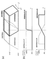
探触子003を傾斜させる理由は、マッチング材005を介して保持部材002と変換素子004間に生じる多重反射を抑制させるためである。この原理について図5を用いて説明する。図5は、探触子003が備える変換素子004群と、保持部材002の相対位置関係を示す。図5における矢印は、両者の間で伝播する超音波を示している。なお、実際の保持部材002は曲率を有しているが、理解を容易にするために、図5では近似的に平面で表している。
The reason for inclining the
図5(a)のように素子面の延長面と保持部材面の延長面が平行である場合、発生した多重反射信号が残留しやすい。それに対し、図5(b)のように素子面の延長面と保持部材面の延長面が交差する関係にあると、多重反射信号は変換素子004群から外れる方向に伝播する。
As shown in FIG. 5A, when the extended surface of the element surface and the extended surface of the holding member surface are parallel, the generated multiple reflection signal tends to remain. On the other hand, when the extended surface of the element surface and the extended surface of the holding member surface intersect as shown in FIG. 5B, the multiple reflection signal propagates in a direction away from the
図5(a)、図5(b)では単純化して示したが、実際の保持部材002は被検体001の形状に沿うように曲率を持っている。そのため、図5(c)のように、探触子の走査により素子面が移動した各位置において、素子面の法線方向における保持部材の全接平面
と、素子面の延長面とが交差していれば、多重反射を抑制できる。言い換えると、素子面と、その素子面と対向する位置にある保持部材の接平面とが平行にならないように、探触子が傾けられる必要がある。なお図5(c)では、素子面上の点からの法線と、保持部材の表面との交点における接平面を、2つ例示している。本発明では、このように、素子面と対向する保持部材上の領域における全接平面が、素子面の延長面と交差するような傾き制御を行う。
5A and 5B, the actual holding
ここで、保持部材は曲率を持っているので、探触子の走査位置によって、適切な傾斜角度は変化する。そのため以下の各実施例では、複数の探触子を設けたり、探触子の傾きを変化させる機構を設けたりしている。
また、素子面と対向する保持部材上の領域は、必ずしも素子面からの正射影に限られず、素子の指向性に応じてある程度の広がりを持っていても良い。なお、素子面と対向する保持部材上の領域とは、素子面上の領域内の点からの法線方向にある保持部材上の領域を指す。接平面を考えるときは、この保持部材上の領域に対する全接平面を想定すれば良く、素子面からの正射影の範囲から外れる部分については検討しなくても良い。
Here, since the holding member has a curvature, an appropriate inclination angle changes depending on the scanning position of the probe. Therefore, in each of the following embodiments, a plurality of probes are provided, or a mechanism for changing the inclination of the probe is provided.
Further, the region on the holding member facing the element surface is not necessarily limited to the orthogonal projection from the element surface, and may have a certain extent according to the directivity of the element. In addition, the area | region on the holding member facing an element surface refers to the area | region on the holding member in the normal line direction from the point in the area | region on an element surface. When considering a tangent plane, it is only necessary to assume a tangential plane with respect to the region on the holding member, and it is not necessary to examine a portion outside the range of the orthogonal projection from the element surface.
探触子003の傾斜方向によって、多重反射の抑制効果は変化する。図5(d)、図5(e)を用いて説明する。多くの探触子003は変換素子004のサイズと配列に応じて長辺と短辺が存在する。同じ傾斜角度であっても、短辺に平行な回転軸で傾いた図5(d)の場合の音響波は変換素子004群から逃れ難いが、長辺に平行な回転軸で傾いた図5(e)の場合の音響波は変換素子004群の外に逃げ易い。そのため、図5(e)のように長辺に平行な回転軸で傾いた方が好ましい。
The effect of suppressing multiple reflections varies depending on the inclination direction of the
以上のことをまとめると、好適な傾斜角度は以下の2条件によって規定される。
(1)素子面の延長面と、素子面と対向する保持部材上の領域における全ての接平面とは、交差している(平行ではない)。
(2)素子面と接平面は、少なくとも素子面の長辺に平行な回転軸を中心として傾斜している。
In summary, the preferred inclination angle is defined by the following two conditions.
(1) The extended surface of the element surface and all tangential planes in the region on the holding member facing the element surface intersect (not parallel).
(2) The element surface and the tangential plane are inclined at least about a rotation axis parallel to the long side of the element surface.
以上、2項目が成立する傾斜角度になるように、傾斜調整機構006にて探触子003を固定する。なお、多重反射を抑制する傾斜角度は、以下の項目で決定する。
(a)変換素子004、保持部材002、マッチング材019の音響インピーダンス
(b)変換素子004、探触子003の短辺の長さ
(c)変換素子004と保持部材002の距離
As described above, the
(A) Acoustic impedance of
上記の項目が判明している場合、シミュレーションや実験により、多重反射によるアーティファクトの出力画像に対する影響度を算出できる。なお、傾斜角度を大きくすると、多重反射の低減効果は大きくなる反面、指向性の都合上受信感度低下のおそれがある。よって、傾斜角度は、アーティファクトの画像への影響度が所定の閾値より低下する程度で十分である。この閾値をユーザの入力値に設定することも好ましい。また、変換素子004と保持部材002の距離によっては、多重反射のエコー信号が画像データ取得時間外に到達する場合もある。その時は、アーティファクトが画像に表示されないため、多重反射強度が表示レベル内の角度であっても構わない。
When the above items are known, the degree of influence of the artifact due to multiple reflection on the output image can be calculated by simulation or experiment. If the tilt angle is increased, the effect of reducing multiple reflections increases, but there is a risk that reception sensitivity may be reduced due to directivity. Therefore, the inclination angle is sufficient such that the degree of influence of the artifact on the image is lower than a predetermined threshold. It is also preferable to set this threshold value to a user input value. Further, depending on the distance between the
保持部材002は被検体001の形状に沿うように曲率を持った形状になるのが好ましい。そのため全撮像領域における探触子003の適した傾斜角度は場所によって異なる。そこで、図4に示すように走査領域を分割し探触子003の傾斜角度を変化させる。この走査領域の分割数と、各走査領域の範囲、および、各走査領域における探触子の傾斜角度は、保持部材003の形態によって決まる。形態とは保持部材003の被検体001保持時における形状と音響インピーダンスのことである。
The holding
駆動制御部009が、ユーザに指定された、または予め定められた撮像範囲に基づいて、駆動機構008を制御することで、探触子が走査領域内を移動する。また、傾斜角度の調整は、典型的には後述する傾斜制御部020が傾斜調整機構007を駆動することで行われる。また、傾斜角度の調整法として、複数の探触子003を用意しておき、各探触子003の走査領域と傾斜角度を規定する方法もある。後者の場合、予め、既知の保持部材003の形態とマッチング材005の音響特性に基づき、各探触子003の走査領域と傾斜角度を規定しておく必要がある。
The
(3次元画像の作成)
信号処理部011および3次元画像合成部012は、各走査領域で探触子003が取得した音響波に基づいて一連の画像再構成処理を行い、複数の3次元画像データを取得する。3次元画像合成部012は、この3次元画像データを、各走査領域の座標位置に対応するように配列する。探触子003は走査面に対し傾斜しているため、取得される画像データ群は、傾斜方向に歪んだ座標系にて配列される。
(Create 3D image)
The
このことを、図6を用いて説明する。図6(a)、図6(b)に、それぞれ異なる傾斜角度を持つ探触子003が被検体001の上を太い矢印方向に移動しながら画像データを取得する様子を示した。図6(c)、図6(d)には、図6(a)、図6(b)それぞれで取得した画像データを、探触子003の移動順に並べた3次元画像データを示した。
This will be described with reference to FIG. FIG. 6A and FIG. 6B show how the
実空間座標xyzに対し、図6(a)では、Bモードスキャン方向をx、ビームフォーミング方向をy、探触子走査方向をzとしている。この場合、図6(c)のように、取得データ配列は実空間座標xyzに対応する。
一方、図6(b)では探触子003を傾斜させており、このときのBモードスキャン方向をα、ビームフォーミング方向をβ、探触子走査方向をγと置く。この場合、図6(d)のように、取得データ配列は取得データ空間座標αβγに対応する。この図6(d)に示した配列の画像データは実空間座標xyzと対応していないため、画像が歪んで表示される。なお、この時ビームフォーミングの方向は素子面に対し垂直方向に実施されていると仮定して説明したが、ビームステアリングを施した場合は、その傾き分だけ取得データ空間座標αβγが変化する。
For the real space coordinates xyz, in FIG. 6A, the B-mode scan direction is x, the beamforming direction is y, and the probe scan direction is z. In this case, as shown in FIG. 6C, the acquired data array corresponds to the real space coordinates xyz.
On the other hand, in FIG. 6B, the
画像を実空間座標と対応して表示させるためには、図6(e)に示すように、取得された3次元画像データを画像変換部012にて実空間座標に変換する必要がある。画像変換手法として例えば、2次元のアフィン変換を繰り返す方法や、探触子003の傾斜角度や回転軸からの距離から算出した座標値に変換する手法を利用できる。なお、画像データの補間方法はバイキュービック法等の近似手法が好ましいが、ニアレストネイバー法、バイリニア法でも補間可能である。
In order to display the image corresponding to the real space coordinates, it is necessary to convert the acquired three-dimensional image data into real space coordinates by the
画像変換部013にて、実空間座標に変換された複数の3次元画像データが作成される。これらの3次元画像データは画像結合部014によって結合され、全走査領域の3次元画像が作成される。なお、走査領域の範囲を設定する際は、各走査領域に対応する各3次元画像の結合部に重畳領域を設けることが好ましい。これにより、結合した際の境界部が目立たないようにすることができる。結合部の重畳方法は、各走査領域の重畳領域中央からの距離に対応して重みを持たせるのが好ましいが、均一な重みでも構わない。
The
画像表示部021は、画像結合部014で結合された画像データを表示する。画像表示部021としては、液晶ディスプレイ、プラズマディスプレイ、有機ELディスプレイ、FEDなどを利用できる。なお、この画像表示部021は必ずしもシステムに搭載させる必要は無い。本システムでは画像データのみを作成し、別の画像表示装置に画像データを
送信して画像を表示させることも可能である。
上記のように探触子の角度制御および走査方法、ならびに走査領域の設定方法によれば、超音波の送信とエコー波の受信における多重反射を抑制できるので、アーティファクトが少なく診断に役立つ画像を表示できる。
The image display unit 021 displays the image data combined by the
As described above, according to the probe angle control and scanning method, and the setting method of the scanning area, multiple reflections in ultrasonic transmission and echo wave reception can be suppressed, so an image useful for diagnosis with few artifacts is displayed. it can.
[実施例1]
(装置の構成)
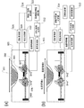
本実施例の被検体情報取得装置のシステム概略図を図7に示す。測定対象は、生体の乳房等の被検体001である。被検体情報取得装置は、保持部材002、超音波探触子003、マッチング材005、キャリッジ006、傾斜調整機構007、駆動機構008を備える。装置はさらに、駆動制御部009、送信制御部010、信号処理部011、3次元画像合成部012、画像変換部013、画像結合部014を備える。
[Example 1]
(Device configuration)
FIG. 7 shows a system schematic diagram of the subject information acquiring apparatus of the present embodiment. The measurement target is a subject 001 such as a living body breast. The subject information acquisition apparatus includes a holding
なお、駆動制御部から画像結合部までの構成要素は、プロセッサ、記憶装置、メモリ、入出力手段などを備えてプログラムにより動作する情報処理装置によって実現されても良いし、各構成要素の機能を持つ回路によって実現されても良い。前者の場合、実際のプログラムモジュール構成は限定されない。また、プログラムの装置上の配置は一体に限られず、例えばオンライン接続された複数の装置で動作してもよい。また、図中の各ブロックを結ぶ線は、その図を説明するために必要な電気信号や制御信号の送受信を示す便宜上のものである。このことは、下記の各実施例でも同様である。 The components from the drive control unit to the image combining unit may be realized by an information processing device that includes a processor, a storage device, a memory, an input / output unit, and the like and operates according to a program. You may implement | achieve by the circuit which has. In the former case, the actual program module configuration is not limited. Further, the arrangement of the program on the device is not limited to a single unit, and may be operated by a plurality of devices connected online, for example. Also, the lines connecting the blocks in the figure are for convenience showing transmission / reception of electric signals and control signals necessary for explaining the figure. This is the same in the following embodiments.
(装置の動作)
まず超音波画像装置部分について説明する。超音波探触子003としては256chの1Dリニアプローブを2つ使用した。この探触子003を構成する変換素子004は、中心周波数が8MHz、素子サイズが4mmのPZTである。各素子は、ラテラル素子ピッチが0.2mmになるよう一列に配列されている。
(Device operation)
First, the ultrasonic image apparatus portion will be described. Two 256-channel 1D linear probes were used as the
被検体を保持する保持部材002には厚さ0.5mmのPET樹脂からなる半球お椀形状の、片方の乳房が全て入るサイズのものを用いた。保持部材を複数用意しておき、乳房のサイズや形状に応じて取替え可能とすることは好ましい。マッチング材005には水を使用し、ポンプで循環させながらヒーターを用いて水温を35℃付近に保つようにした。水温を35℃付近に保つ理由は、被検者に不快な思いをさせない事と、マッチング材005の音速を規定し画像再構成の精度を向上させるためである。水温の制御方法はこの限りでは無く、別の手法を用いても構わない。また、水温の制御は再構成の精度を向上させる点では好ましいが、必ずしも必須ではないため、室温で安定したマッチング材005を使用しても構わない。
As the holding
送信制御部010により、任意の位置に超音波送信フォーカスを形成するための電気信号(制御信号)が各変換素子004に送られる。制御信号は、各変換素子004素子において超音波に変換され、被検体001へと送信される。この超音波は被検体001によって反射・散乱されて再び超音波エコーとして受信開口を形成する複数の変換素子004に受信される。なお、本実施例では64個の変換素子004群から受信開口を形成し、各受信信号は画像処理部011に送られ、整相加算処理、ヒルベルト変換、包絡線検波、LOG圧縮を経て、走査ライン上の画像データが再構成される。その走査ラインを探触子003ラテラル方向に移動させることで2次元画像データを再構成する。
The
次に探触子の駆動方法について説明する。
図7の例においては、2つの超音波探触子003を別々のキャリッジ006に異なる傾斜角度で設置し、異なる走査領域を走査させた。図7(b)は探触子003側から保持部材002を見た図である。保持部材の中央部に重畳領域が生じるように2つの走査領域A
、Bが設定されており、2つの探触子A,Bがそれぞれを走査する。本実施例では探触子003のエレベーション方向を主走査方向、ラテラル方向を副走査方向と規定し、主走査時に超音波送受信を実施する。
Next, a method for driving the probe will be described.
In the example of FIG. 7, two
, B are set, and the two probes A, B scan each of them. In this embodiment, the elevation direction of the
傾斜調整機構007は、各探触子003を、副走査方向に平行な回転軸を中心として回転させる。各探触子の素子面は、保持部材の中心側に向けてではなく、外側に向けて傾けられる。ただし、素子面の正射影が完全に保持部材から外れてしまうと超音波の被検体への送受信ができなくなるので、素子面の対向位置に保持部材が含まれる範囲の傾斜角度に留める必要がある。傾斜角度は、各変換素子が有意な強度で音響波を受信できる指向角と、アーティファクトの低減効果が得られる角度により決定され、シミュレーションや実験により定めることが好ましい。
The
本実施例では、図7(a)における紙面左右方向を回転軸として、探触子Aは15度、探触子Bは−15度の傾きを持つ。各探触子003は保持部材002との最短距離が10mmになるように設置している。この傾斜角度は、変換素子004、マッチング材005、保持部材002の音響インピーダンスと、変換素子004の幅(4mm)と、変換素子004と保持部材距離(最短10mm)等から算出される。音響インピーダンスは、PZT:30,水:1.5,PET:3[MegaRayls]とする。本実施例の15度という値は、シミュレーション結果や実験値から算出したものであり、条件に応じて最適な設置角度は変わる。
In the present embodiment, the probe A has an inclination of 15 degrees and the probe B has an inclination of −15 degrees, with the horizontal direction in FIG. Each
また、本実施例では2つの探触子A,Bを用いて走査領域をA、Bの2つにサブ走査領域に分割したが、分割数や領域の設定方法はこれに限られない。例えば図7(c)、図7(d)はともに、4つの探触子A,B,C,Dを用いて、4つの異なるサブ走査領域A,B,C,Dを設定した例を示している。
図7(c)では、全走査領域が主走査方向において4つに区分されている。この場合、探触子A,Dの傾斜角度を探触子B,Cに対して少なく設定すると良い。これは、外側の領域ほど保持部材の曲率が大きくなり、保持部材の表面が走査面となす角度が大きい分、探触子の傾きが小さくても多重反射が起こりにくくなるからである。例えば探触子A:10度、B:15度、C:−15度、D:−10度とする。これはサブ走査領域A,Dの方が、保持部材接平面と走査面の交差角が大きく、また変換素子004群と保持部材002距離が長いため、探触子003の傾斜角が小さくても多重反射の影響を小さく出来るためである。
In this embodiment, the scanning area is divided into two sub-scanning areas A and B using two probes A and B. However, the number of divisions and the method for setting the area are not limited to this. For example, FIGS. 7C and 7D show examples in which four different sub-scanning regions A, B, C, and D are set using four probes A, B, C, and D, respectively. ing.
In FIG. 7C, the entire scanning area is divided into four in the main scanning direction. In this case, the inclination angles of the probes A and D are preferably set to be small with respect to the probes B and C. This is because the curvature of the holding member becomes larger in the outer region, and multiple reflections are less likely to occur even if the inclination of the probe is small because the angle formed by the surface of the holding member and the scanning surface is larger. For example, the probe A is 10 degrees, B is 15 degrees, C is -15 degrees, and D is -10 degrees. In the sub-scanning areas A and D, the crossing angle between the tangent plane of the holding member and the scanning plane is larger, and the distance between the
図7(d)では、図7(b)における走査領域を更に副走査方向に2分割している。そして、探触子を、変換素子004群の長辺に平行な回転軸を用いて主走査方向に傾けるのみでなく、短辺に平行な回転軸も用いて副走査方向にも傾けている。実施例では、主走査方向の傾きは図7(b)と同じ±15度とし、副走査方向の傾きは、素子面が保持部材002中央部に向くように15度に設定した。この副走査方向への傾きは、送受信ビームが保持部材002に対して垂直に近い角度で入射する値に設定する。このように角度を設定することで、スネルの法則に基づく保持部材面での屈折、反射等の影響が低減される。そのため、多重反射軽減に必要な最低限の傾斜角度を確保した後は、可能な限り送受信ビームを保持部材002に垂直入射させるのが良く、図7(c)、図7(d)ともにこの理由で走査領域の分割数を増やしている。しかし、サブ走査領域の数が多くなると、駆動制御や画像処理が複雑になる点で注意を要する。
In FIG. 7D, the scanning region in FIG. 7B is further divided into two in the sub-scanning direction. The probe is not only tilted in the main scanning direction using the rotation axis parallel to the long side of the
キャリッジ006は駆動機構部008によって移動する。本実施例ではモータにはパルスモータを使用している。キャリッジ006を、パルスモータとボールねじを組み合わせた駆動機構部008によって2軸方向に任意の位置に任意の速度で移動させる。そして駆動制御部009によってサブ走査領域A,Bを走査するように設定した。
The
3次元画像合成部012は、2次元画像データを座標位置に対応して配列し、サブ走査領域A,Bそれぞれにおける3次元画像データを作成する。画像変換部012は、これらの3次元画像データ間の探触子003の傾斜角度の違いによる影響を吸収するために、実空間座標に変換する。この変換処理について、図6(b)、図6(d)、図6(e)を用いて説明する。図6(b)は実空間座標xyzに対する、所定の角度だけ傾いた探触子003の画像情報取得時の様子を示している。図6(d)には、図6(b)の状態の探触子が受信した音響波に由来する、3次元画像合成部012にて配列された画像データを示している。図6(e)には、図6(d)の画像データから、画像変換部013によって実空間座標xyzに変換された画像データを示している。
The three-dimensional
ここで、サブ走査領域(典型的には、探触子の傾き角度が相異なるサブ走査領域同士)の画像データ同士の結合には、図6(e)への変換(実空間座標への変換)が必要である。本実施例では探触子003の回転軸を中心に、傾斜角度と距離に対応した回転座標の式を用いて座標変換を実施した。この座標変換の結果、取得データ空間座標のデータを抽出するのに補間が必要になる。本実施例では、各実空間座標xyzに対応する取得データ空間座標α,β,γの周辺64画像データを基に、α,β,γ3軸の方向にバイキュービック補間と同様の3次式で補間する手法を用いて参照値を算出した。
Here, for the combination of image data in sub-scanning regions (typically, sub-scanning regions having different probe tilt angles), conversion to FIG. 6E (conversion to real space coordinates) is performed. )is necessary. In this embodiment, the coordinate conversion is performed using the rotation coordinate formula corresponding to the tilt angle and the distance around the rotation axis of the
画像結合部013は、実空間座標に対応させた3次元画像データを、サブ走査領域の境界部分に位置する重畳領域で結合し、全走査領域の3次元画像データを作成する。図8を用いて、本実施例にて採用した重畳領域の画像処理について説明する。図8(a)に、サブ走査領域A、Bにてそれぞれ取得した実空間座標の取得画像領域A、Bを示している。取得画像領域A、Bの重なった領域が重畳領域である。図8(b)に、y=y1,y2における各z座標の2画像データの合成比率を示す。重畳領域の中央座標において両方の重み比率が等しく50%になるように設定し、中央座標からの距離に対応した重みを用いている。このような重みを用いる事で、境界が目立たない結合画像を実現できる。なお、図7(d)のような走査領域区分において、x方向(副走査方向)の画像の結合が必要になるが、同様に合成すればよい。
The
また、サブ走査領域同士のx方向の画像の結合も、z方向と同様の重み比率を用いて実施できる。これは、同じ取得データ空間座標において結合できる処理であることと、事前に同じ走査領域での画像データをまとめておくことで、画像変換部013での実空間座標への変換処理がまとめて実施できる利点があるためである。
Further, the combination of the images in the x direction between the sub-scanning regions can be performed using the same weight ratio as in the z direction. This is a process that can be combined in the same acquired data space coordinates, and the image data in the same scanning area is collected in advance, so that the conversion process to the real space coordinates in the
以上の処理によって、全撮像領域の3次元画像データが完成する。この3次元画像データは液晶ディスプレイにて任意の断面画像を確認出来るようにしている。
以上のように、探触子の角度調整を適切に行うことにより、カップ形状の保持部材002にて保持した乳房を撮像して3次元超音波画像を生成する際に、多重反射によるアーティファクトを抑制する効果が得られた。また、複数のサブ走査領域に分けた撮像結果を合成するときに、重畳部分の違和感を防止できた。
Through the above processing, the three-dimensional image data of the entire imaging region is completed. The three-dimensional image data allows an arbitrary cross-sectional image to be confirmed on a liquid crystal display.
As described above, by appropriately adjusting the angle of the probe, artifacts due to multiple reflections are suppressed when a breast held by the cup-shaped holding
[実施例2]
本実施例において、装置の構成と基本的な動作は実施例1と同じである。主な相違点は、本実施例では探触子003が1つである点と、傾斜制御部020が存在する点である。傾斜制御部020は、サブ走査領域ごとに探触子003の傾斜量を変更するために、傾斜調整機構007を制御する。傾斜調整機構007にはステッピングモータを内蔵した回転自動ステージを使用した。
[Example 2]
In the present embodiment, the configuration and basic operation of the apparatus are the same as those in the first embodiment. The main difference is that in this embodiment, there is one
実施例の詳細を、図9を用いて説明する。
まず、傾斜制御部020が傾斜調整機構007を駆動して、探触子003の傾斜角度を15度に設定する。その状態でサブ走査領域Aの画像データを取得し、画像変換部013までの処理を実施する。その後、傾斜制御部020が傾斜調整機構を駆動して探触子003傾斜角度を−15度に設定する。その状態でサブ走査領域Bの画像データを取得し、画像変換部013までの処理を実施する。以上の処理で作成された2つの3次元画像データを画像結合部014にて結合する。
Details of the embodiment will be described with reference to FIG.
First, the
以上のシステムを用いて、半球のカップ形状の保持部材002にて保持した乳房を撮像した。その結果、1つの探触子でも、多重反射によるアーティファクトを除去した乳房の3次元超音波画像を取得できた。
Using the above system, the breast held by the hemispherical cup-shaped holding
[実施例3]
本実施例において、装置の構成と基本的な動作は実施例2と同じである。主な相違点は、保持部材特性算出部023および探触子駆動計算部024が存在する点である。保持部材特性算出部023は、保持部材002の形状と音響特性を算出する。探触子駆動計算部024は、算出された保持部材002の形態より探触子003の駆動方法を決定する。
[Example 3]
In this embodiment, the configuration and basic operation of the apparatus are the same as those in the second embodiment. The main difference is that a holding member
実施例の詳細を、図10を用いて説明する。
本実施例では、加圧によって形状が変化するシリコーンゴムシートを保持部材002として用いる。撮像開始前に、乳房をシリコーンゴムシートにおしつけ、シートの形状が安定するのを待つ。
Details of the embodiment will be described with reference to FIG.
In this embodiment, a silicone rubber sheet whose shape changes with pressure is used as the holding
図10(a)は、実際に特性情報を取得する前の、保持部材の形状を取得する処理(プレスキャン処理)を示す。撮像開始後、まず、探触子003の傾斜角度を、走査面に対し垂直に超音波が送受信されるように設定し、全撮像領域の超音波信号を取得する。そして保持部材特性算出部023が、各座標における最初に取得される強エコー信号の受信時間と信号強度から、保持部材002の形状と部材の反射強度を算出する。
FIG. 10A shows a process (pre-scan process) for acquiring the shape of the holding member before actually acquiring the characteristic information. After the start of imaging, first, the inclination angle of the
続いて、探触子駆動計算部024が、保持部材の特性情報と、既知である探触子003と変換素子004の形状と音響特性、およびマッチング材005の音響特性を基に、走査領域の分割方法と各領域での探触子003の傾斜角度を決定する。
探触子駆動計算部024は、この処理を、事前に探触子003情報とマッチング材005の特性から、シミュレーションや実験を実施して作成した対応表を基に行うと良い。この対応表には、各座標における変換素子004から保持部材002までの距離と反射強度の値に対応した多重反射回避角度が設定されている。また、保持部材特性算出部023によって保持部材002の形状が判明しているため、各座標における探触子傾斜角度を変化させたときの、変換素子004群の法線方向における保持部材002接平面の角度も算出できる。これらのデータを基に、撮像領域内の各座標における、探触子の最小傾斜角度を算出する。
探触子駆動計算部024は、全撮像領域における最小傾斜角度分布から、走査領域の分割と、各領域における探触子傾斜角度を設定する。
Subsequently, the probe
The probe
The probe
なお、保持部材002としてシリコーンゴムシートを用いる場合、加圧によって形状は変形するが、音響特性は変化しない。そのため、保持部材特性算出部023では形状のみを算出し、保持部材002の音響特性としては既知の値を利用しても良い。この場合、探触子駆動計算部024は形状のみで場合分けされた対応表を用いて撮像条件を決定する。このようにすれば、対応表の条件数が少なくなるため、処理の規模を抑制できる。
また、事前に保持部材の形状を把握し、その情報を基に走査領域の分割と、探触子003傾斜角度を算出できれば、上記以外の手法でも構わない。
When a silicone rubber sheet is used as the holding
Any method other than those described above may be used as long as the shape of the holding member is grasped in advance and the division of the scanning region and the
保持部材としてPET等を用いた場合、シリコーンゴムシートに比べて変形の程度は少ないものの、本実施例の保持部材の形状取得方法を適用してもよい。また、PET等の保持部材は変形が少ない分、乳房のサイズや形状に応じて複数個用意しておき、被検者を支持する部材に設けた取付部において取替え可能とすることが好ましい。このように保持部材を取替え可能とする場合、予め上記の対応表を作成するときに、各保持部材ごとの数値を記録しておくと良い。そして、被検体情報取得装置は、保持部材の種類をICタグやバーコード、あるいはユーザによる入力値に基づき取得し、メモリから適切な対応表を取得すると良い。 When PET or the like is used as the holding member, although the degree of deformation is less than that of the silicone rubber sheet, the method for acquiring the shape of the holding member of this embodiment may be applied. In addition, it is preferable that a plurality of holding members such as PET are prepared in accordance with the size and shape of the breast, so that they can be replaced at the mounting portion provided on the member that supports the subject, because of less deformation. When the holding member can be replaced in this way, it is preferable to record a numerical value for each holding member when the correspondence table is created in advance. Then, the subject information acquisition apparatus may acquire the type of the holding member based on the IC tag, the barcode, or the input value by the user, and acquire an appropriate correspondence table from the memory.
上記の処理により測定および画像生成時の諸条件を决定したのち、図10(b)に示すように実際の撮像が行われる。例えば、角度α=15°、角度β=−15°などである。被検体情報取得装置は、探触子駆動計算部024によって決定された条件に従って、実施例2に記載の処理を実施し、3次元画像を作成する。
After determining the conditions at the time of measurement and image generation by the above processing, actual imaging is performed as shown in FIG. For example, angle α = 15 °, angle β = −15 °, and the like. The subject information acquisition apparatus performs the process described in the second embodiment according to the conditions determined by the probe
以上のシステムを用いて、未知の形態の保持部材002にて保持した乳房を撮像した。その結果、ゴムシートの様な形状が変化する保持部材を用いた場合でも、多重反射によるアーティファクトを除去した乳房の3次元超音波画像を実現した。
Using the above system, the breast held by the holding
[実施例4]
本実施例において、装置の構成と基本的な動作は実施例3と同じである。主な相違点は、画像取得手段025が存在する点である。
[Example 4]
In the present embodiment, the configuration and basic operation of the apparatus are the same as those in the third embodiment. The main difference is that image acquisition means 025 exists.
実施例の詳細を、図11を用いて説明する。
実施例3と同様に、保持部材002としてシリコーンゴムシートを利用し、乳房に押し付けたシリコーンゴムシートの形状が安定するのを待つ。本実施例では、撮像の前に画像取得手段025にて乳房側面の画像を取得する。実施例ではCCDカメラを2台使用し、主走査方向および副走査方向の2側面の側面画像を取得した。
Details of the embodiment will be described with reference to FIG.
As in the third embodiment, a silicone rubber sheet is used as the holding
保持部材特性算出部023は、CCDカメラで取得した画像に基づき、乳房におしつけられ変形したシリコーンゴムの形状を抽出する。抽出手法としては既知の様々な画像処理、例えば特徴量を2値化処理する手法が利用できる。そして、2側面の形状データから、シリコーンゴムシートの3次元形状を算出する。保持部材の形状が取得できるものであれば、画像取得手段の種類や設置位置、設置数は問わない。例えばCCDカメラに変えてCMOSカメラでも良い。また、設置位置としては、探触子を構成する容器(支持体)の上端や、光出射位置の近辺などは、全体像を取得する上で効果的である。また、設置する数や設置方向を増やすことで、算出する精度は向上する。
The holding member
探触子駆動計算部024はこの情報を用いて、既知である探触子003と変換素子004の形状と音響特性、及び、マッチング材005と保持部材002であるシリコーンゴムの音響特性を基に、走査領域の分割と各領域での探触子003の傾斜角度を決定する。後の処理は実施例3と同じである。
以上のシステムを用いて、シリコーンゴムシートにて保持した乳房を撮像した。その結果、プレスキャンを行わずに保持部材002の形状を算出し、探触子の駆動条件を設定する事で、多重反射によるアーティファクトを除去した乳房の3次元超音波画像を実現した。
Using this information, the probe
Using the above system, the breast held by the silicone rubber sheet was imaged. As a result, the shape of the holding
[実施例5]
本実施例では、装置の構成と基本的な動作は実施例1から4と同じである。主な相違点は、被検体情報取得装置が、超音波画像装置ではなく光音響画像装置だという点である。
[Example 5]
In the present embodiment, the configuration and basic operation of the apparatus are the same as those in the first to fourth embodiments. The main difference is that the object information acquiring apparatus is not an ultrasonic image apparatus but a photoacoustic image apparatus.
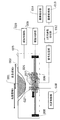
本実施例について、図12を用いて説明する。キャリッジ006には光音響波用の探触子026と光源027を取り付け、探触子026は傾斜調整機構006にて傾斜角度が調整できる。光源027は光源制御部028にて制御される。
光音響画像装置について説明する。光源027は、被検体に対してパルス光を照射する。本実施例では光源として、固体レーザーの一種であるチタンサファイアレーザーを採用する。光源として、固体レーザー、ガスレーザー、色素レーザー、半導体レーザーなどのレーザーが好適である。また、レーザーの代わりに発光ダイオードなどを用いても良い。光源からの光は近赤外線が好ましく用いられ、波長に関しても650nmから1100nm程度の波長が利用できる。実施例では750nmを使用している。
This embodiment will be described with reference to FIG. A
A photoacoustic image apparatus will be described. The
光源027から照射された光は、被検体001内を伝播して吸収される。例えば、生体に上述の近赤外線を照射すると、生体内の血液および血管において特異的に吸収され、熱膨張により音響波が発生する。生体内にがんが存在する場合は、がんの新生血管において光が特異的に吸収され、光音響波が発生する。
Light emitted from the
なお、本実施例では光源027をキャリッジ006に設置し、探触子026とともに移動させ、撮像部分に効率よく光が照射されるように設置しているが、必要な光音響波が発生出来ればキャリッジ006以外の個所に搭載しても構わない。この光源027は光源制御部028により制御され、10Hzの間隔でパルス光を照射している。
実施例で用いている光音響探触子026は、1mm×1mmの変換素子600個(20×30配列)から構成される。変換素子004はPZTを採用し、中心周波数は2MHzに調整されている。受信された光音響波は各変換素子004にてアナログ信号に変換される。アナログ信号は信号処理部010において画像データに再構成される。
以上の処理以外の一連の部分は、実施例1から4までの処理と同じである。
In this embodiment, the
The
A series of portions other than the above processing is the same as the processing in the first to fourth embodiments.
なお、本実施例では2Dプローブを使用している。探触子026は、主走査方向と短辺が平行に、副走査方向と長辺が平行になるようにキャリッジ006に設置される。そして、長辺に平行な回転軸を用いて探触子026を主走査方向に傾斜するように傾斜調整機構007で調整している。しかし、探触子026の取り付けを90°回転させて、副走査方向に傾斜するように傾斜調整機構007を調整しても同じ効果が得られる。ただしこの場合は、保持部材002の形状等によって、最適な走査領域の分割と傾斜角度が変化する。いずれにせよ、素子面と保持部材接平面が少なくとも変換素子群の長辺に平行な回転軸に対して傾斜するように交差していれば探触子026を傾斜する方向は問わない。
In this embodiment, a 2D probe is used. The
傾斜角度について、光超音波画像装置と超音波装置ではアーティファクトの伝播経路に違いがあるため、算出手法が一部異なる。超音波画像装置の場合、変換素子004から送信された超音波が保持部材002との間を2往復以上したものがアーティファクトとなり、このエコー信号を軽減するための傾斜角を設定する。
Regarding the tilt angle, the calculation method is partially different between the optical ultrasonic imaging apparatus and the ultrasonic apparatus because there is a difference in the propagation path of the artifact. In the case of an ultrasonic imaging apparatus, an ultrasonic wave transmitted from the
一方、光超音波画像装置の場合、光源027から光が照射されると、保持部材002の表面と探触子026の表面にて振動が生じ、それぞれ音響波が発生する。この音響波が変換素子004と保持部材002の間を多重反射したものが、アーティファクトとなる。探触子026表面にて発生した音響波は超音波画像装置と同じ2往復以上するとアーティファクトとなるが、保持部材002にて発生した音響波は1.5往復以上するとアーティファクトとなる。そのため、多重反射を受信しない傾斜角度は光音響の方が大きくなる傾向にある。また、本実施例のように探触子026の短辺の長さが比較的長くなると傾斜角度は大きくなる。そのため、完全に多重反射信号を受信しない角度の実現は難しくなる。
このような場合、アーティファクト信号がある閾値以下になる傾斜角度に設定するのが好ましい。本実施例では、目的の被検体画像情報の音響信号に対し40dB程度にアーテ
ィファクト信号が抑えられる角度を一つの目安にしている。
On the other hand, in the case of the optical ultrasonic imaging apparatus, when light is irradiated from the
In such a case, it is preferable to set the inclination angle at which the artifact signal becomes a certain threshold value or less. In this embodiment, an angle at which the artifact signal is suppressed to about 40 dB with respect to the acoustic signal of the target object image information is set as one guide.
保持部材002の形態が既知にせよ未知にせよ、傾斜角度は超音波画像装置の場合と同様に、シミュレーションや実験の結果より対応表を作成し、その対応表より決定する。そして、保持部材002の形態が既知の場合は、予め走査範囲の分割と各探触子026の傾斜角度を設定しておく。また、未知の場合は、プレスキャンや保持部材002画像の取得、解析により保持部材002の形状を把握し、対応表より、走査範囲の分割と各探触子026の傾斜角度を決定し、画像を撮像すればよい。
Regardless of whether the shape of the holding
本実施例では厚み1mmのポリメチルペンテンで出来た半球のカップ形状の保持部材002を用いた。また、図7(b)に示すように2つのサブ走査領域を設けた。それぞれの傾斜角度は探触子Aが10度、探触子Bが−10度になるように、傾斜調整機構007を調整した。この時探触子026と保持部材002の最短距離は10mmに設定している。
以上のシステムを用いて、保持部材002にて保持した乳房を撮像した。多重反射によるアーティファクトを軽減した乳房の3次元光超音波画像を実現した。
In this embodiment, a hemispherical cup-shaped holding
The breast held by the holding
以上、各実施例で説明したように、本発明によれば、保持部材にて保持された被検体に対して探触子を走査させる被検体情報取得装置において、探触子の変換素子面と保持部材間にて生じる多重反射を抑制し低減できる。
本発明では、曲率を持った保持部材に保持される被検体の上に探触子を走査させる被検体情報取得装置において、探触子の変換素子群の法線方向における被検体保持部材の全ての接平面に対し、探触子の素子面が交差するように探触子を傾斜させる。これにより、探触子の素子面と被検体保持部材の間で発生する多重反射が抑制される。
As described above, according to the present invention, according to the present invention, in the subject information acquisition apparatus that scans the probe with respect to the subject held by the holding member, the transducer conversion element surface and Multiple reflections occurring between the holding members can be suppressed and reduced.
In the present invention, in the subject information acquiring apparatus that scans the probe on the subject held by the holding member having a curvature, all of the subject holding members in the normal direction of the transducer conversion element group The probe is inclined so that the element surface of the probe intersects the tangent plane. Thereby, the multiple reflection which generate | occur | produces between the element surface of a probe and a subject holding member is suppressed.
002:保持部材,003:超音波探触子,004:変換素子,008:駆動機構,009:駆動制御部,011:信号処理部 002: Holding member, 003: Ultrasonic probe, 004: Conversion element, 008: Drive mechanism, 009: Drive control unit, 011: Signal processing unit
Claims (13)
前記被検体から伝播する音響波を受信して電気信号を出力する複数の変換素子が配列された素子面を持つ探触子と、
前記探触子を前記保持部材に対向する走査面の走査領域において走査させる駆動機構と、
前記電気信号を用いて前記被検体内部の特性情報を取得する情報処理手段と、
を有し、
前記探触子は、走査する各位置において、前記素子面の延長面と、前記素子面に対向する前記保持部材上の領域における当該保持部材の接平面とが交差するような傾斜角度を持つ
ことを特徴とする被検体情報取得装置。 A holding member having a curvature for holding the subject;
A probe having an element surface on which a plurality of conversion elements that receive an acoustic wave propagating from the subject and output an electrical signal are arranged;
A drive mechanism for causing the probe to scan in a scanning region of a scanning surface facing the holding member;
Information processing means for acquiring characteristic information inside the subject using the electrical signal;
Have
The probe has an inclination angle such that an extended surface of the element surface and a tangential plane of the holding member in a region on the holding member facing the element surface intersect at each position to be scanned. A subject information acquisition apparatus characterized by the above.
前記探触子は、走査する各位置において、前記素子面の延長面が、前記正射影に含まれるすべての点における接平面に対して平行とはならないような傾斜角度を持つ
ことを特徴とする請求項1に記載の被検体情報取得装置。 The region on the holding member facing the element surface is an orthogonal projection from the element surface to the holding member,
The probe is characterized in that an extended surface of the element surface has an inclination angle that is not parallel to a tangential plane at all points included in the orthogonal projection at each position to be scanned. The subject information acquisition apparatus according to claim 1.
ことを特徴とする請求項1または2に記載の被検体情報取得装置。 The object information acquiring apparatus according to claim 1, wherein the probe is tilted about a rotation axis parallel to a long side of the element surface.
前記探触子は、前記素子面が前記保持部材の外側に向けて傾くような傾斜角度を持つ
ことを特徴とする請求項3に記載の被検体情報取得装置。 The holding member has a cup shape with a center portion protruding toward the probe side,
The object information acquiring apparatus according to claim 3, wherein the probe has an inclination angle such that the element surface is inclined toward the outside of the holding member.
前記複数の探触子のそれぞれは、前記走査領域を分割した複数のサブ走査領域における前記保持部材の形状に応じた傾斜角度を持ち、対応する前記サブ走査領域において前記音響波を受信する
ことを特徴とする請求項1ないし4のいずれか1項に記載の被検体情報取得装置。 A plurality of the probes;
Each of the plurality of probes has an inclination angle corresponding to the shape of the holding member in a plurality of sub-scanning regions obtained by dividing the scanning region, and receives the acoustic wave in the corresponding sub-scanning region. 5. The subject information acquiring apparatus according to claim 1, wherein the subject information acquiring apparatus is characterized in that:
ことを特徴とする請求項5に記載の被検体情報取得装置。 The information processing means creates image data based on the characteristic information for each of the plurality of sub-scanning regions and combines the plurality of image data to create three-dimensional image data inside the subject. The subject information acquisition apparatus according to claim 5.
ことを特徴とする請求項1ないし6のいずれか1項に記載の被検体情報取得装置。 The object information acquiring apparatus according to claim 1, further comprising an inclination control unit that changes an inclination angle of the probe.
ことを特徴とする請求項1ないし7のいずれか1項に記載の被検体情報取得装置。 8. The probe according to claim 1, wherein the inclination angle of the probe decreases as the curvature of the holding member increases and the angle formed by the surface of the holding member with the scanning surface increases. 2. The subject information acquisition apparatus according to the item.
前記情報処理手段は、前記保持部材特性算出部からの出力を用いて前記保持部材の曲率を取得する
ことを特徴とする請求項1ないし8のいずれか1項に記載の被検体情報取得装置。 Based on an acoustic wave propagating from the holding member, further includes a holding member characteristic calculation unit that acquires at least one of the shape and acoustic characteristics of the holding member,
The object information acquiring apparatus according to claim 1, wherein the information processing unit acquires a curvature of the holding member using an output from the holding member characteristic calculation unit.
前記情報処理手段は、前記保持部材特性算出部からの出力を用いて前記保持部材の曲率を取得する
ことを特徴とする請求項1ないし8のいずれか1項に記載の被検体情報取得装置。 It further has an image acquisition means for acquiring an image of the holding member,
The object information acquiring apparatus according to claim 1, wherein the information processing unit acquires a curvature of the holding member using an output from the holding member characteristic calculation unit.
ことを特徴とする請求項1ないし10のいずれか1項に記載の被検体情報取得装置。 The object information acquiring apparatus according to claim 1, further comprising a matching material that propagates an acoustic wave between the holding member and the probe.
ことを特徴とする請求項1ないし11のいずれか1項に記載の被検体情報取得装置。 The object information acquiring apparatus according to claim 1, wherein the acoustic wave propagating from the subject is an echo wave reflected after being transmitted from the conversion element.
ことを特徴とする請求項1ないし11のいずれか1項に記載の被検体情報取得装置。 The object information acquiring apparatus according to claim 1, wherein the acoustic wave propagating from the subject is a photoacoustic wave generated from the subject irradiated with light. .
Priority Applications (2)
| Application Number | Priority Date | Filing Date | Title |
|---|---|---|---|
| JP2014234754A JP2016096914A (en) | 2014-11-19 | 2014-11-19 | Subject information acquisition device |
| US14/939,003 US20160135688A1 (en) | 2014-11-19 | 2015-11-12 | Object information acquiring apparatus |
Applications Claiming Priority (1)
| Application Number | Priority Date | Filing Date | Title |
|---|---|---|---|
| JP2014234754A JP2016096914A (en) | 2014-11-19 | 2014-11-19 | Subject information acquisition device |
Publications (2)
| Publication Number | Publication Date |
|---|---|
| JP2016096914A true JP2016096914A (en) | 2016-05-30 |
| JP2016096914A5 JP2016096914A5 (en) | 2017-12-28 |
Family
ID=55960621
Family Applications (1)
| Application Number | Title | Priority Date | Filing Date |
|---|---|---|---|
| JP2014234754A Pending JP2016096914A (en) | 2014-11-19 | 2014-11-19 | Subject information acquisition device |
Country Status (2)
| Country | Link |
|---|---|
| US (1) | US20160135688A1 (en) |
| JP (1) | JP2016096914A (en) |
Cited By (2)
| Publication number | Priority date | Publication date | Assignee | Title |
|---|---|---|---|---|
| JP2017049215A (en) * | 2015-09-04 | 2017-03-09 | 菱電湘南エレクトロニクス株式会社 | Ultrasonic flaw detecting device, probe, and ultrasonic flaw detecting method |
| JP2020519346A (en) * | 2017-05-11 | 2020-07-02 | コーニンクレッカ フィリップス エヌ ヴェKoninklijke Philips N.V. | Echo artifact cancellation in ultrasound diagnostic images |
Families Citing this family (10)
| Publication number | Priority date | Publication date | Assignee | Title |
|---|---|---|---|---|
| KR101937065B1 (en) * | 2014-09-05 | 2019-01-09 | 캐논 가부시끼가이샤 | Object information acquiring apparatus |
| JP6594355B2 (en) | 2017-01-06 | 2019-10-23 | キヤノン株式会社 | Subject information processing apparatus and image display method |
| US10904514B2 (en) | 2017-02-09 | 2021-01-26 | Facebook Technologies, Llc | Polarization illumination using acousto-optic structured light in 3D depth sensing |
| JP2018126389A (en) * | 2017-02-09 | 2018-08-16 | キヤノン株式会社 | Information processing apparatus, information processing method, and program |
| US10613413B1 (en) | 2017-05-31 | 2020-04-07 | Facebook Technologies, Llc | Ultra-wide field-of-view scanning devices for depth sensing |
| US10181200B1 (en) | 2017-06-28 | 2019-01-15 | Facebook Technologies, Llc | Circularly polarized illumination and detection for depth sensing |
| US10574973B2 (en) | 2017-09-06 | 2020-02-25 | Facebook Technologies, Llc | Non-mechanical beam steering for depth sensing |
| JP7000139B2 (en) * | 2017-12-01 | 2022-01-19 | キヤノン株式会社 | Image information processing device and display method |
| WO2020117486A1 (en) * | 2018-12-05 | 2020-06-11 | Verathon Inc. | Implant assessment using ultrasound and optical imaging |
| WO2023087070A1 (en) * | 2021-11-18 | 2023-05-25 | Vexev Pty Ltd | Apparatus for ultrasound scanning |
Citations (4)
| Publication number | Priority date | Publication date | Assignee | Title |
|---|---|---|---|---|
| JPH02264641A (en) * | 1989-04-04 | 1990-10-29 | Fuji Electric Co Ltd | Ultrasonic wave probe |
| JP2012152544A (en) * | 2011-01-07 | 2012-08-16 | Canon Inc | Measuring apparatus |
| JP2012179348A (en) * | 2011-02-10 | 2012-09-20 | Canon Inc | Acoustic-wave acquisition apparatus |
| JP2012235850A (en) * | 2011-05-11 | 2012-12-06 | Konica Minolta Medical & Graphic Inc | Ultrasonic diagnostic apparatus |
Family Cites Families (2)
| Publication number | Priority date | Publication date | Assignee | Title |
|---|---|---|---|---|
| JP4610721B2 (en) * | 2000-11-22 | 2011-01-12 | 株式会社ソミック石川 | Ball joint and method for manufacturing the same |
| US6907224B2 (en) * | 2001-03-15 | 2005-06-14 | Qualcomm Incorporated | Time acquisition in a wireless position determination system |
-
2014
- 2014-11-19 JP JP2014234754A patent/JP2016096914A/en active Pending
-
2015
- 2015-11-12 US US14/939,003 patent/US20160135688A1/en not_active Abandoned
Patent Citations (4)
| Publication number | Priority date | Publication date | Assignee | Title |
|---|---|---|---|---|
| JPH02264641A (en) * | 1989-04-04 | 1990-10-29 | Fuji Electric Co Ltd | Ultrasonic wave probe |
| JP2012152544A (en) * | 2011-01-07 | 2012-08-16 | Canon Inc | Measuring apparatus |
| JP2012179348A (en) * | 2011-02-10 | 2012-09-20 | Canon Inc | Acoustic-wave acquisition apparatus |
| JP2012235850A (en) * | 2011-05-11 | 2012-12-06 | Konica Minolta Medical & Graphic Inc | Ultrasonic diagnostic apparatus |
Cited By (3)
| Publication number | Priority date | Publication date | Assignee | Title |
|---|---|---|---|---|
| JP2017049215A (en) * | 2015-09-04 | 2017-03-09 | 菱電湘南エレクトロニクス株式会社 | Ultrasonic flaw detecting device, probe, and ultrasonic flaw detecting method |
| JP2020519346A (en) * | 2017-05-11 | 2020-07-02 | コーニンクレッカ フィリップス エヌ ヴェKoninklijke Philips N.V. | Echo artifact cancellation in ultrasound diagnostic images |
| JP7333273B2 (en) | 2017-05-11 | 2023-08-24 | コーニンクレッカ フィリップス エヌ ヴェ | Echo Artifact Cancellation in Diagnostic Ultrasound Images |
Also Published As
| Publication number | Publication date |
|---|---|
| US20160135688A1 (en) | 2016-05-19 |
Similar Documents
| Publication | Publication Date | Title |
|---|---|---|
| JP2016096914A (en) | Subject information acquisition device | |
| JP6489797B2 (en) | Subject information acquisition device | |
| EP3530192B1 (en) | Device and method for hybrid optoacoustic tomography and ultrasonography | |
| JP5448918B2 (en) | Biological information processing device | |
| JP5489624B2 (en) | measuring device | |
| JP2010167257A (en) | Biological information acquisition apparatus | |
| JP2010167258A (en) | Biological information acquisition apparatus | |
| US10064558B2 (en) | Subject information acquisition device, method for controlling subject information acquisition device, and storage medium storing program therefor | |
| JP2016209452A (en) | Subject information acquisition device | |
| JP6261159B2 (en) | Subject information acquisition apparatus and subject information acquisition method | |
| KR102457217B1 (en) | Probe and manufacturing method thereof | |
| US11006929B2 (en) | Object information acquiring apparatus and signal processing method | |
| JP6598487B2 (en) | Subject information acquisition device | |
| JP2017047178A (en) | Subject information acquisition device | |
| JP5572023B2 (en) | measuring device | |
| JP2017140092A (en) | Subject information acquisition device | |
| EP3415097B1 (en) | Acoustic wave image generation device and acoustic wave image generation method | |
| US20150320321A1 (en) | Object information acquiring apparatus | |
| JP2017202313A (en) | Acoustic wave reception device | |
| JP6942847B2 (en) | Subject information acquisition device and signal processing method | |
| JP5868458B2 (en) | measuring device | |
| JP2017202312A (en) | Acoustic wave reception device |
Legal Events
| Date | Code | Title | Description |
|---|---|---|---|
| A521 | Request for written amendment filed |
Free format text: JAPANESE INTERMEDIATE CODE: A523 Effective date: 20171116 |
|
| A621 | Written request for application examination |
Free format text: JAPANESE INTERMEDIATE CODE: A621 Effective date: 20171116 |
|
| A977 | Report on retrieval |
Free format text: JAPANESE INTERMEDIATE CODE: A971007 Effective date: 20180726 |
|
| A131 | Notification of reasons for refusal |
Free format text: JAPANESE INTERMEDIATE CODE: A131 Effective date: 20180828 |
|
| A521 | Request for written amendment filed |
Free format text: JAPANESE INTERMEDIATE CODE: A523 Effective date: 20181016 |
|
| A02 | Decision of refusal |
Free format text: JAPANESE INTERMEDIATE CODE: A02 Effective date: 20181030 |
|
| RD02 | Notification of acceptance of power of attorney |
Free format text: JAPANESE INTERMEDIATE CODE: A7422 Effective date: 20181116 |