JP6253323B2 - Subject information acquisition apparatus and control method thereof - Google Patents
Subject information acquisition apparatus and control method thereof Download PDFInfo
- Publication number
- JP6253323B2 JP6253323B2 JP2013199836A JP2013199836A JP6253323B2 JP 6253323 B2 JP6253323 B2 JP 6253323B2 JP 2013199836 A JP2013199836 A JP 2013199836A JP 2013199836 A JP2013199836 A JP 2013199836A JP 6253323 B2 JP6253323 B2 JP 6253323B2
- Authority
- JP
- Japan
- Prior art keywords
- subject
- receiving
- scanning
- distribution information
- display
- Prior art date
- Legal status (The legal status is an assumption and is not a legal conclusion. Google has not performed a legal analysis and makes no representation as to the accuracy of the status listed.)
- Active
Links
Images


Classifications
-
- A—HUMAN NECESSITIES
- A61—MEDICAL OR VETERINARY SCIENCE; HYGIENE
- A61B—DIAGNOSIS; SURGERY; IDENTIFICATION
- A61B8/00—Diagnosis using ultrasonic, sonic or infrasonic waves
- A61B8/44—Constructional features of the ultrasonic, sonic or infrasonic diagnostic device
- A61B8/4416—Constructional features of the ultrasonic, sonic or infrasonic diagnostic device related to combined acquisition of different diagnostic modalities, e.g. combination of ultrasound and X-ray acquisitions
-
- A—HUMAN NECESSITIES
- A61—MEDICAL OR VETERINARY SCIENCE; HYGIENE
- A61B—DIAGNOSIS; SURGERY; IDENTIFICATION
- A61B5/00—Measuring for diagnostic purposes; Identification of persons
- A61B5/0093—Detecting, measuring or recording by applying one single type of energy and measuring its conversion into another type of energy
- A61B5/0095—Detecting, measuring or recording by applying one single type of energy and measuring its conversion into another type of energy by applying light and detecting acoustic waves, i.e. photoacoustic measurements
-
- A—HUMAN NECESSITIES
- A61—MEDICAL OR VETERINARY SCIENCE; HYGIENE
- A61B—DIAGNOSIS; SURGERY; IDENTIFICATION
- A61B8/00—Diagnosis using ultrasonic, sonic or infrasonic waves
- A61B8/08—Detecting organic movements or changes, e.g. tumours, cysts, swellings
-
- A—HUMAN NECESSITIES
- A61—MEDICAL OR VETERINARY SCIENCE; HYGIENE
- A61B—DIAGNOSIS; SURGERY; IDENTIFICATION
- A61B8/00—Diagnosis using ultrasonic, sonic or infrasonic waves
- A61B8/08—Detecting organic movements or changes, e.g. tumours, cysts, swellings
- A61B8/0825—Detecting organic movements or changes, e.g. tumours, cysts, swellings for diagnosis of the breast, e.g. mammography
-
- A—HUMAN NECESSITIES
- A61—MEDICAL OR VETERINARY SCIENCE; HYGIENE
- A61B—DIAGNOSIS; SURGERY; IDENTIFICATION
- A61B8/00—Diagnosis using ultrasonic, sonic or infrasonic waves
- A61B8/44—Constructional features of the ultrasonic, sonic or infrasonic diagnostic device
- A61B8/4444—Constructional features of the ultrasonic, sonic or infrasonic diagnostic device related to the probe
- A61B8/4461—Features of the scanning mechanism, e.g. for moving the transducer within the housing of the probe
-
- A—HUMAN NECESSITIES
- A61—MEDICAL OR VETERINARY SCIENCE; HYGIENE
- A61B—DIAGNOSIS; SURGERY; IDENTIFICATION
- A61B8/00—Diagnosis using ultrasonic, sonic or infrasonic waves
- A61B8/46—Ultrasonic, sonic or infrasonic diagnostic devices with special arrangements for interfacing with the operator or the patient
- A61B8/461—Displaying means of special interest
-
- A—HUMAN NECESSITIES
- A61—MEDICAL OR VETERINARY SCIENCE; HYGIENE
- A61B—DIAGNOSIS; SURGERY; IDENTIFICATION
- A61B8/00—Diagnosis using ultrasonic, sonic or infrasonic waves
- A61B8/46—Ultrasonic, sonic or infrasonic diagnostic devices with special arrangements for interfacing with the operator or the patient
- A61B8/467—Ultrasonic, sonic or infrasonic diagnostic devices with special arrangements for interfacing with the operator or the patient characterised by special input means
- A61B8/469—Ultrasonic, sonic or infrasonic diagnostic devices with special arrangements for interfacing with the operator or the patient characterised by special input means for selection of a region of interest
-
- A—HUMAN NECESSITIES
- A61—MEDICAL OR VETERINARY SCIENCE; HYGIENE
- A61B—DIAGNOSIS; SURGERY; IDENTIFICATION
- A61B8/00—Diagnosis using ultrasonic, sonic or infrasonic waves
- A61B8/52—Devices using data or image processing specially adapted for diagnosis using ultrasonic, sonic or infrasonic waves
- A61B8/5207—Devices using data or image processing specially adapted for diagnosis using ultrasonic, sonic or infrasonic waves involving processing of raw data to produce diagnostic data, e.g. for generating an image
-
- G—PHYSICS
- G01—MEASURING; TESTING
- G01S—RADIO DIRECTION-FINDING; RADIO NAVIGATION; DETERMINING DISTANCE OR VELOCITY BY USE OF RADIO WAVES; LOCATING OR PRESENCE-DETECTING BY USE OF THE REFLECTION OR RERADIATION OF RADIO WAVES; ANALOGOUS ARRANGEMENTS USING OTHER WAVES
- G01S15/00—Systems using the reflection or reradiation of acoustic waves, e.g. sonar systems
- G01S15/88—Sonar systems specially adapted for specific applications
- G01S15/89—Sonar systems specially adapted for specific applications for mapping or imaging
- G01S15/8906—Short-range imaging systems; Acoustic microscope systems using pulse-echo techniques
- G01S15/8909—Short-range imaging systems; Acoustic microscope systems using pulse-echo techniques using a static transducer configuration
- G01S15/8915—Short-range imaging systems; Acoustic microscope systems using pulse-echo techniques using a static transducer configuration using a transducer array
- G01S15/8925—Short-range imaging systems; Acoustic microscope systems using pulse-echo techniques using a static transducer configuration using a transducer array the array being a two-dimensional transducer configuration, i.e. matrix or orthogonal linear arrays
-
- G—PHYSICS
- G01—MEASURING; TESTING
- G01S—RADIO DIRECTION-FINDING; RADIO NAVIGATION; DETERMINING DISTANCE OR VELOCITY BY USE OF RADIO WAVES; LOCATING OR PRESENCE-DETECTING BY USE OF THE REFLECTION OR RERADIATION OF RADIO WAVES; ANALOGOUS ARRANGEMENTS USING OTHER WAVES
- G01S15/00—Systems using the reflection or reradiation of acoustic waves, e.g. sonar systems
- G01S15/88—Sonar systems specially adapted for specific applications
- G01S15/89—Sonar systems specially adapted for specific applications for mapping or imaging
- G01S15/8906—Short-range imaging systems; Acoustic microscope systems using pulse-echo techniques
- G01S15/8934—Short-range imaging systems; Acoustic microscope systems using pulse-echo techniques using a dynamic transducer configuration
- G01S15/8938—Short-range imaging systems; Acoustic microscope systems using pulse-echo techniques using a dynamic transducer configuration using transducers mounted for mechanical movement in two dimensions
-
- G—PHYSICS
- G01—MEASURING; TESTING
- G01S—RADIO DIRECTION-FINDING; RADIO NAVIGATION; DETERMINING DISTANCE OR VELOCITY BY USE OF RADIO WAVES; LOCATING OR PRESENCE-DETECTING BY USE OF THE REFLECTION OR RERADIATION OF RADIO WAVES; ANALOGOUS ARRANGEMENTS USING OTHER WAVES
- G01S15/00—Systems using the reflection or reradiation of acoustic waves, e.g. sonar systems
- G01S15/88—Sonar systems specially adapted for specific applications
- G01S15/89—Sonar systems specially adapted for specific applications for mapping or imaging
- G01S15/8906—Short-range imaging systems; Acoustic microscope systems using pulse-echo techniques
- G01S15/8993—Three dimensional imaging systems
-
- G—PHYSICS
- G01—MEASURING; TESTING
- G01S—RADIO DIRECTION-FINDING; RADIO NAVIGATION; DETERMINING DISTANCE OR VELOCITY BY USE OF RADIO WAVES; LOCATING OR PRESENCE-DETECTING BY USE OF THE REFLECTION OR RERADIATION OF RADIO WAVES; ANALOGOUS ARRANGEMENTS USING OTHER WAVES
- G01S15/00—Systems using the reflection or reradiation of acoustic waves, e.g. sonar systems
- G01S15/88—Sonar systems specially adapted for specific applications
- G01S15/89—Sonar systems specially adapted for specific applications for mapping or imaging
- G01S15/8906—Short-range imaging systems; Acoustic microscope systems using pulse-echo techniques
- G01S15/8997—Short-range imaging systems; Acoustic microscope systems using pulse-echo techniques using synthetic aperture techniques
-
- G—PHYSICS
- G01—MEASURING; TESTING
- G01S—RADIO DIRECTION-FINDING; RADIO NAVIGATION; DETERMINING DISTANCE OR VELOCITY BY USE OF RADIO WAVES; LOCATING OR PRESENCE-DETECTING BY USE OF THE REFLECTION OR RERADIATION OF RADIO WAVES; ANALOGOUS ARRANGEMENTS USING OTHER WAVES
- G01S7/00—Details of systems according to groups G01S13/00, G01S15/00, G01S17/00
- G01S7/52—Details of systems according to groups G01S13/00, G01S15/00, G01S17/00 of systems according to group G01S15/00
- G01S7/52017—Details of systems according to groups G01S13/00, G01S15/00, G01S17/00 of systems according to group G01S15/00 particularly adapted to short-range imaging
- G01S7/52053—Display arrangements
- G01S7/52057—Cathode ray tube displays
- G01S7/5206—Two-dimensional coordinated display of distance and direction; B-scan display
- G01S7/52063—Sector scan display
-
- A—HUMAN NECESSITIES
- A61—MEDICAL OR VETERINARY SCIENCE; HYGIENE
- A61B—DIAGNOSIS; SURGERY; IDENTIFICATION
- A61B8/00—Diagnosis using ultrasonic, sonic or infrasonic waves
- A61B8/48—Diagnostic techniques
- A61B8/483—Diagnostic techniques involving the acquisition of a 3D volume of data
Landscapes
- Engineering & Computer Science (AREA)
- Physics & Mathematics (AREA)
- Health & Medical Sciences (AREA)
- Life Sciences & Earth Sciences (AREA)
- Remote Sensing (AREA)
- Radar, Positioning & Navigation (AREA)
- Acoustics & Sound (AREA)
- General Physics & Mathematics (AREA)
- Computer Networks & Wireless Communication (AREA)
- Surgery (AREA)
- Veterinary Medicine (AREA)
- Molecular Biology (AREA)
- Heart & Thoracic Surgery (AREA)
- Animal Behavior & Ethology (AREA)
- General Health & Medical Sciences (AREA)
- Public Health (AREA)
- Medical Informatics (AREA)
- Biomedical Technology (AREA)
- Biophysics (AREA)
- Pathology (AREA)
- Nuclear Medicine, Radiotherapy & Molecular Imaging (AREA)
- Radiology & Medical Imaging (AREA)
- Computer Vision & Pattern Recognition (AREA)
- Ultra Sonic Daignosis Equipment (AREA)
Description
本発明は、被検体情報取得装置およびその制御方法に関する。 The present invention relates to a subject information acquisition apparatus and a control method thereof.
従来、医療画像診断に用いられる超音波診断装置において、超音波の送受信機能を備えた振動素子を含む探触子が用いられている。この探触子から被検体に向けて、超音波の合成によって形成される超音波ビームを送信すると、超音波ビームは被検体内部における音響インピーダンスが変化する領域(すなわち、組織の境界)において反射する。探触子がこの反射エコーを受信し、その強度に基づいて情報処理装置が画像再構成することにより、生体組織の形態分布情報を示す2次元画像データ(断層スライス像)が取得できる。 Conventionally, in an ultrasonic diagnostic apparatus used for medical image diagnosis, a probe including a vibration element having an ultrasonic wave transmission / reception function is used. When an ultrasonic beam formed by synthesis of ultrasonic waves is transmitted from the probe toward the subject, the ultrasonic beam is reflected in a region where the acoustic impedance changes inside the subject (that is, the boundary of the tissue). . The probe receives this reflected echo, and the information processing apparatus reconstructs the image based on the intensity thereof, whereby two-dimensional image data (tomographic slice image) indicating the morphological distribution information of the living tissue can be acquired.
特許文献1の技術によれば、1次元配列(1Dアレイ)探触子を用いて被検体表面をXY方向に機械的に走査することで、連続した断層スライス像を得られる。これにより、広い検査領域の3次元画像データを生成できる。 According to the technique of Patent Document 1, a continuous tomographic slice image can be obtained by mechanically scanning the subject surface in the XY directions using a one-dimensional array (1D array) probe. Thereby, three-dimensional image data of a wide inspection area can be generated.
一方、非特許文献1には、光音響トモグラフィー(PAT:Photoacoustic Tomography)技術を適用した、乳がん検査用の生体情報イメージング装置が記載されている。
PATとは、被検体内で伝播・拡散した光のエネルギーを吸収した生体組織から光音響効果により発生した光音響波を用いて、被検体内部の光学特性値に関連した情報を可視化する技術である。その際、被検体を取り囲む複数の個所で光音響波を検出し、得られた信号を数学的に解析処理する。
On the other hand, Non-Patent Document 1 describes a biological information imaging apparatus for breast cancer examination to which a photoacoustic tomography (PAT) technique is applied.
PAT is a technology that visualizes information related to optical property values inside a subject using photoacoustic waves generated by a photoacoustic effect from living tissue that has absorbed the energy of light propagated and diffused within the subject. is there. At that time, photoacoustic waves are detected at a plurality of locations surrounding the subject, and the obtained signal is mathematically analyzed.
光音響効果とは、被検体にパルス光を照明すると、被検体内の吸収係数が高い領域で、体積膨張により光音響波が発生する現象である。
PATでは、光照射によって生じた初期音圧分布あるいは光エネルギー吸収密度分布など、特定成分の有無や変化を示す、生体組織の機能分布情報を取得できる。
The photoacoustic effect is a phenomenon in which when a subject is irradiated with pulsed light, a photoacoustic wave is generated due to volume expansion in a region having a high absorption coefficient in the subject.
With PAT, it is possible to acquire biological tissue functional distribution information indicating the presence or absence of specific components, such as the initial sound pressure distribution or light energy absorption density distribution generated by light irradiation.
さらに特許文献1では、光音響波を受信するための2次元配列(2Dアレイ)探触子と、超音波を送受信する1次元配列探触子とが一体化された探触子を用いて、被検体表面をXY方向に機械的走査を行う構成に関しても記載されている。 Furthermore, in Patent Document 1, using a probe in which a two-dimensional array (2D array) probe for receiving photoacoustic waves and a one-dimensional array probe for transmitting and receiving ultrasonic waves are integrated, It also describes a configuration in which the subject surface is mechanically scanned in the XY directions.
しかし、特許文献1のように、2種類の受信機能が一体化された探触子を機械的に走査して3次元画像データを生成する場合、探触子の全走査が完了するまでの間、超音波エコーと光音響波の双方に由来する画像データを確認することができなかった。その理由を以下に説明する。 However, in the case of generating three-dimensional image data by mechanically scanning a probe in which two types of reception functions are integrated as in Patent Document 1, until the probe is completely scanned. The image data derived from both the ultrasonic echo and the photoacoustic wave could not be confirmed. The reason will be described below.
光音響波に基づく画像再構成を行う際には、画像化対象領域全体からの受信データが必要となる。したがって、画像化対象領域を走査している途中に、走査の済んだ場所から順次画像生成し、リアルタイムで表示することは不可能である。そのため従来、探触子の全走査が完了してから画像再構成処理を行って3次元画像データを生成していた。なお、画像化対象領域とは、被検体全体を指す場合もあるし、被検体を分割した部分領域の一つを指す場合もある。 When performing image reconstruction based on photoacoustic waves, received data from the entire imaging target area is required. Therefore, it is impossible to sequentially generate images from the scanned locations and display them in real time while scanning the imaging target area. For this reason, conventionally, after all scanning of the probe is completed, image reconstruction processing is performed to generate three-dimensional image data. Note that the imaging target region may refer to the entire subject or one of partial regions obtained by dividing the subject.
一方、超音波の画像再構成に関しては通常、リアルタイムでの画像生成が可能である。しかし特許文献1の装置は、主として光音響画像に重畳表示させる目的で超音波画像を生成していたため、探触子の全走査が完了するまで超音波画像を表示する機能が無かった。 On the other hand, with respect to ultrasound image reconstruction, it is usually possible to generate images in real time. However, since the apparatus of Patent Document 1 generates an ultrasonic image mainly for the purpose of superimposing and displaying it on a photoacoustic image, it has no function of displaying an ultrasonic image until the entire scanning of the probe is completed.
本発明は上記課題に鑑みてなされたものであり、その目的は、光音響波および超音波エコーを用いて被検体内の対象領域の画像データを生成する装置において、探触子による対象領域全体の走査の完了を待たずに画像データの確認を可能とすることにある。 The present invention has been made in view of the above problems, and an object of the present invention is to provide an entire target region by a probe in an apparatus that generates image data of a target region in a subject using photoacoustic waves and ultrasonic echoes. Therefore, it is possible to confirm image data without waiting for the completion of scanning.
本発明は、以下の構成を採用する。すなわち、
被検体に送信されたのち当該被検体で反射した超音波、および、光を照射された前記被
検体で発生した光音響波を受信する受信手段と、
前記受信手段を前記被検体に対して機械的に走査する走査手段と、
前記超音波を用いて前記被検体内の形態分布情報を生成するとともに、前記光音響波を用いて前記被検体内の機能分布情報を生成する処理手段と、
前記形態分布情報および前記機能分布情報を表示手段に表示させる制御を行う制御手段と、
前記被検体における関心領域の指定を受け付ける入力手段と、
を有し、
前記制御手段は、前記受信手段が前記被検体の少なくとも一部の領域からなる部分領域からの光音響波を受信して、前記処理手段が当該部分領域の機能分布情報を生成する期間に、前記処理手段が前記被検体の前記部分領域から反射した超音波に基づき生成した形態分布情報を、前記走査手段による前記部分領域内における前記受信手段の走査に伴い順次、前記表示手段に表示させる制御を行うものであり、
前記処理手段は、前記関心領域において、前記光音響波を用いた前記機能分布情報の生成を行うものであり、
前記入力手段は、前記制御手段が前記形態分布情報を順次、前記表示手段に表示させているときに、前記関心領域の変更を受け付けることが可能であり、
前記走査手段は、変更された前記関心領域に基づいて前記受信手段の経路を変更する
ことを特徴とする被検体情報取得装置である。
The present invention employs the following configuration. That is,
Receiving means for receiving ultrasonic waves reflected by the subject after being transmitted to the subject and photoacoustic waves generated by the subject irradiated with light;
Scanning means for mechanically scanning the receiving means with respect to the subject;
Processing means for generating morphological distribution information in the subject using the ultrasound and generating functional distribution information in the subject using the photoacoustic wave;
Control means for controlling the display means to display the form distribution information and the function distribution information;
Input means for receiving designation of a region of interest in the subject;
Have
The control means receives a photoacoustic wave from a partial area consisting of at least a partial area of the subject, and the processing means generates functional distribution information of the partial area. Control for causing the display means to sequentially display the morphological distribution information generated based on the ultrasound reflected from the partial area of the subject by the processing means as the receiving means scans the partial area by the scanning means. What to do ,
Pre Symbol processing means, in the region of interest, which performs generation of the functional distribution information using the photoacoustic wave,
The input means can accept a change of the region of interest when the control means is sequentially displaying the morphological distribution information on the display means,
The scanning means changes the path of the receiving means based on the changed region of interest.
本発明はまた、以下の構成を採用する。すなわち、
受信手段と、前記受信手段を被検体に対して機械的に走査する走査手段と、処理手段と、形態分布情報および機能分布情報を表示手段に表示させる制御を行う制御手段と、入力手段と、
を有する被検体情報取得装置の制御方法であって、
前記受信手段が、前記被検体に送信されたのち前記被検体で反射した超音波を受信するステップと、
前記受信手段が、光を照射された前記被検体で発生した光音響波を受信するステップと、
前記処理手段が、前記超音波を用いて前記被検体内の形態分布情報を生成するステップと、
前記処理手段が、前記光音響波を用いて前記被検体内の機能分布情報を生成するステップと、
前記制御手段が、前記受信手段が前記被検体の少なくとも一部の領域からなる部分領域からの光音響波を受信して、前記処理手段が当該部分領域の機能分布情報を生成する期間に、前記処理手段が前記被検体の前記部分領域から反射した超音波に基づき生成した形態分布情報を、前記走査手段による前記部分領域内における前記受信手段の走査に伴い順次、前記表示手段に表示させる制御を行うステップと、
前記入力手段が、前記被検体における関心領域の指定を受け付けるステップと、
前記処理手段が、前記関心領域において、前記光音響波を用いた前記機能分布情報の生成を行うステップと、
前記入力手段が、前記制御手段が前記形態分布情報を順次、前記表示手段に表示させているときに、前記関心領域の変更を受け付けるステップと、
前記走査手段が、変更された前記関心領域に基づいて前記受信手段の経路を変更するステップと、
を有することを特徴とする被検体情報取得装置の制御方法である。
The present invention also employs the following configuration. That is,
A receiving means, a scanning means for mechanically scanning the receiving means with respect to the subject, a processing means, a control means for controlling the display means to display morphological distribution information and functional distribution information, an input means,
A method for controlling a subject information acquisition apparatus comprising:
Receiving the ultrasound reflected by the subject after being transmitted to the subject;
Receiving the photoacoustic wave generated by the subject irradiated with light; and
The processing means generates morphological distribution information in the subject using the ultrasound; and
The processing means generating functional distribution information in the subject using the photoacoustic wave;
The control means receives a photoacoustic wave from a partial area consisting of at least a partial area of the subject, and the processing means generates functional distribution information of the partial area. Control for causing the display means to sequentially display the morphological distribution information generated based on the ultrasound reflected from the partial area of the subject by the processing means as the receiving means scans the partial area by the scanning means. Steps to do,
The input means accepting designation of a region of interest in the subject;
The processing means generating the functional distribution information using the photoacoustic wave in the region of interest;
Receiving the change of the region of interest when the input means causes the control means to sequentially display the morphological distribution information on the display means;
The scanning means changing the path of the receiving means based on the changed region of interest;
A control method for a subject information acquiring apparatus .
本発明によれば、光音響波および超音波エコーを用いて被検体内の対象領域の画像データを生成する装置において、探触子による対象領域全体の走査の完了を待たずに画像データの確認が可能となる。 According to the present invention, in an apparatus that generates image data of a target area in a subject using photoacoustic waves and ultrasonic echoes, the image data can be confirmed without waiting for the probe to scan the entire target area. Is possible.
以下に図面を参照しつつ、本発明の好適な実施の形態について説明する。ただし、以下に記載されている構成部品の寸法、材質、形状およびそれらの相対配置などは、発明が適用される装置の構成や各種条件により適宜変更されるべきものであり、この発明の範囲を以下の記載に限定する趣旨のものではない。 Hereinafter, preferred embodiments of the present invention will be described with reference to the drawings. However, the dimensions, materials, shapes, and relative arrangements of the components described below should be changed as appropriate according to the configuration of the apparatus to which the invention is applied and various conditions. It is not intended to limit the following description.
本発明において、音響波とは、音波、超音波、光音響波、光超音波と呼ばれる弾性波あるいは疎密波を含む。本発明の被検体情報取得装置は、光音響トモグラフィー装置と、超音波装置を兼ねる。前者は、被検体に光(電磁波)を照射し、光音響効果に従って被検体内で発生した光音響波を受信して、被検体内部の特性情報を取得する装置である。後者は、被検体に超音波を送信し、被検体内で反射した超音波(反射エコー)を受信して、被検体内部の特性情報を取得する装置である。 In the present invention, the acoustic wave includes an elastic wave or a dense wave called a sound wave, an ultrasonic wave, a photoacoustic wave, or an optical ultrasonic wave. The subject information acquisition apparatus of the present invention serves as both a photoacoustic tomography apparatus and an ultrasonic apparatus. The former is a device that irradiates a subject with light (electromagnetic waves), receives photoacoustic waves generated in the subject according to the photoacoustic effect, and acquires characteristic information inside the subject. The latter is a device that transmits ultrasonic waves to a subject and receives ultrasonic waves (reflected echoes) reflected within the subject to acquire characteristic information inside the subject.
光音響トモグラフィー(PAT)により取得される特性情報は、光照射によって生じた音響波の初期音圧、初期音圧から導かれる光エネルギー吸収密度や吸収係数、組織を構成する物質の濃度等を反映した被検体情報である。組織を構成する物質は機能を反映することから、光音響特性分布は被検体の機能分布情報を表すと言える。 Characteristic information acquired by photoacoustic tomography (PAT) reflects the initial sound pressure of acoustic waves generated by light irradiation, the absorption density and absorption coefficient of light energy derived from the initial sound pressure, the concentration of substances that make up the tissue, etc. Subject information. Since the substance constituting the tissue reflects the function, it can be said that the photoacoustic characteristic distribution represents the function distribution information of the subject.
物質の濃度とは例えば、酸素飽和度またはオキシヘモグロビン濃度もしくはデオキシヘモグロビン濃度である。また、生成された特性情報は、数値データ、被検体内の各位置の分布情報、または画像を表示するための画像データとして保存や利用されても良い。 The concentration of the substance is, for example, oxygen saturation, oxyhemoglobin concentration, or deoxyhemoglobin concentration. The generated characteristic information may be stored or used as numerical data, distribution information of each position in the subject, or image data for displaying an image.
超音波送受信により取得される特性情報は、被検体内で音響インピーダンスが変化する部位、すなわち異なる音響インピーダンスを持つ領域間の境界位置を反映した被検体情報である。音響インピーダンスの違いは組織の形態を反映することから、音響インピーダンス特性分布は被検体の形態分布情報を表すと言える。 The characteristic information acquired by ultrasonic transmission / reception is subject information reflecting a part where acoustic impedance changes in the subject, that is, a boundary position between regions having different acoustic impedances. Since the difference in acoustic impedance reflects the morphology of the tissue, it can be said that the acoustic impedance characteristic distribution represents the morphology distribution information of the subject.
以下、図面を参照しつつ、本発明を詳細に説明する。なお、同一の構成要素には原則として同一の符号を付して、説明を省略する場合がある。本発明は被検体情報取得装置やその作動方法、制御方法としても捉えられる。本発明はまた、制御方法を情報処理装置等に
実施させるプログラムとしても捉えられる。
Hereinafter, the present invention will be described in detail with reference to the drawings. In principle, the same components are denoted by the same reference numerals, and description thereof may be omitted. The present invention can also be understood as a subject information acquisition apparatus, an operation method thereof, and a control method. The present invention can also be understood as a program for causing an information processing apparatus or the like to execute a control method.
(画像再構成の技術)
理論的には、PATでは、被検体全体を取り囲む閉じられた空間(特に球面)の表面の様々な点において、音響波の時間変化を理想的な音響検出器を用いて測定できれば、光照射により生じた初期音圧分布を完全に可視化できる。理想的な音響検出器とは広帯域、点検出なものを指す。
また、閉じられた空間での測定ではなくとも、被検体を囲む円柱状の空間表面、あるいは被検体に面する平板状の空間表面で音響波を測定できれば、初期音圧分布をほぼ再現できることが数学的に知られている。
(Image reconstruction technology)
Theoretically, in PAT, if the time change of acoustic waves can be measured using an ideal acoustic detector at various points on the surface of a closed space (especially a spherical surface) that surrounds the entire subject, The generated initial sound pressure distribution can be completely visualized. An ideal acoustic detector is a broadband, point detector.
Even if the measurement is not performed in a closed space, if the acoustic wave can be measured on a cylindrical space surface surrounding the subject or a flat surface facing the subject, the initial sound pressure distribution can be substantially reproduced. Mathematically known.
下記式(1)は、PATの基本となる偏微分方程式であり、「光音響波動方程式」と言われる。この式を解けば、初期音圧分布からの音波伝播を記述でき、どの場所で音響波がどのように検出できるかを理論的に求めることができる。ここで、rは位置、tは時間である。p(r,t)は音圧の時間変化、p0(r)は初期音圧分布、cは音速である。δ(t)は光パルスの形状をあらわすデルタ関数である。

一方、PATの画像再構成とは、検出点で得られた音圧pd(rd,t)から初期音圧分布p0(r)を導き出すことであり、数学的には逆問題と呼ばれる。
以下に、PATの画像再構成手法で代表的に使われているUniversal Back Projection(UBP)法に関して説明する。式(1)の光音響波動方程式を周波数空間上で解析することで、p0(r)を求める逆問題を正確に解くことができる。その結果を時間空間上で表したのがUBPである。最終的には、以下の式(2)が導かれる。
ここで、Ω0は任意の再構成ボクセル(あるいはフォーカス点)に対する全体の測定エリアS0の立体角である。
On the other hand, PAT image reconstruction is to derive the initial sound pressure distribution p 0 (r) from the sound pressure p d (r d , t) obtained at the detection point, which is mathematically called an inverse problem. .
Hereinafter, the Universal Back Projection (UBP) method typically used in the PAT image reconstruction method will be described. By analyzing the photoacoustic wave equation of Expression (1) on the frequency space, the inverse problem for obtaining p 0 (r) can be accurately solved. The result is UBP in time space. Ultimately, the following equation (2) is derived.
Here, Ω 0 is the solid angle of the entire measurement area S 0 with respect to an arbitrary reconstructed voxel (or focus point).
さらに、式を分かりやすく変形すると、式(3)となる。
ここで、b(r0,t)は、式(4)で示されるように、投影データである。また、dΩ0は、式(5)で示されるように、任意の観測点Pに対する検出器dS0の立体角である。
この投影データを式(3)の積分に従って逆投影することで、初期音圧分布p0(r)が得られる。
Here, b (r 0 , t) is projection data, as shown in Expression (4). Further, dΩ 0 is a solid angle of the detector dS 0 with respect to an arbitrary observation point P as shown in the equation (5).
By projecting this projection data according to the integration of equation (3), an initial sound pressure distribution p 0 (r) is obtained.
ここで、θは検出器と任意の観測点Pとがなす角度である。音源の大きさに比べて、音源と測定位置の距離が十分大きい場合(遠距離音場近似)、式(6)となる。
また、b(r0,t)は、式(7)となる。
Further, b (r 0 , t) is expressed by Equation (7).
このようにPATの画像再構成では、検出器で得られた検出信号p(r0,t)を時間微分することで投影データb(r0,t)が得られる。これを式(3)に従って逆投影することで、初期音圧分布p0(r)が求まることが知られている。 Thus, in PAT image reconstruction, projection data b (r 0 , t) is obtained by time-differentiating the detection signal p (r 0 , t) obtained by the detector. It is known that the initial sound pressure distribution p 0 (r) can be obtained by back projecting this according to the equation (3).
このようにPATによる画像再構成では、生体等の被検体内の特性情報を画像化できる。特性情報には、光照射によって生じた音響波の発生源分布や、生体内の初期音圧分布、あるいはそれから導かれる光エネルギー吸収密度分布、及びそれらの情報から得られる生体組織を構成する物質の濃度分布がある。これらの特性情報は、例えば、悪性腫瘍や血管疾患などの診断や、化学治療の経過観察の目的で利用できる。 Thus, in the image reconstruction by PAT, the characteristic information in the subject such as a living body can be imaged. The characteristic information includes the source distribution of the acoustic wave generated by light irradiation, the initial sound pressure distribution in the living body, or the light energy absorption density distribution derived therefrom, and the substance constituting the living tissue obtained from the information. There is a concentration distribution. Such characteristic information can be used, for example, for the purpose of diagnosing malignant tumors, vascular diseases, and the like and observing the progress of chemotherapy.
<実施例1>
図1は、本発明の特徴を最もよく表す被検体情報取得装置の全体構成図である。被検体が生体の場合、この装置は生体情報イメージング装置とも呼べる。
<Example 1>
FIG. 1 is an overall configuration diagram of a subject information acquiring apparatus that best represents the features of the present invention. When the subject is a living body, this apparatus can also be called a biological information imaging apparatus.
(装置構成と動作)
CPU1は、装置の主制御を司る。超音波送信部2は、超音波用探触子を駆動して超音波ビームを送信する。超音波受信部3は、超音波用探触子で検出した受信信号を取り込みビーム形成する。光音響波受信部4は、光音響波用探触子で検出した受信信号を取り込む。
1Dアレイ探触子5は、超音波を発生させて反射エコーを検出する。2Dアレイ探触子6は、光音響波の信号検出に使われる。探触子14は、超音波用の探触子5と光音響波用の探触子6を一体化した機構である。
(Device configuration and operation)
The CPU 1 manages the main control of the apparatus. The
The
光照射部7は、被検体に光照射を行う。光源部8は、光照射部を制御する。画像処理部9は、光音響波や超音波からの受信信号を用いて画像データを算出する。表示制御部10は、画像のスキャンコンバートや重畳表示を制御する。ディスプレイ11は、画像データを表示する。走査制御部12は、一体化した探触子14を任意の位置にXY走査する。走
査部13は、探触子の機械的な移動走査を行う。
The
超音波の送受信による画像化の基本動作を説明する。超音波用の探触子5を被検体に当てて超音波を送信すると、その超音波は、ごく短い時間のうちに被検体内を進行し、音響インピーダンスの差がある境界で反射エコーとなる。音響インピーダンスに差があるということは、異なる媒質が接していることを意味する。探触子はその反射エコーを検出する。
A basic operation of imaging by transmitting and receiving ultrasonic waves will be described. When the
そして画像処理部が、超音波を送信してから反射エコーが返ってくるまでの時間から距離を計算することで、被検体内部の組織を画像化する。このようにして、生体組織の物質分布を表す「形態イメージ(形態分布情報)」の画像化が可能となる。
走査制御部は本発明の走査手段に相当する。探触子は本発明の受信手段に相当する。画像処理部は本発明の処理手段に相当する。ディスプレイは本発明の表示手段に相当する。
The image processing unit calculates the distance from the time from when the ultrasonic wave is transmitted until the reflected echo returns, thereby imaging the tissue inside the subject. In this way, it is possible to form a “morphological image (morphological distribution information)” representing the substance distribution of the living tissue.
The scanning control unit corresponds to the scanning unit of the present invention. The probe corresponds to the receiving means of the present invention. The image processing unit corresponds to the processing means of the present invention. The display corresponds to the display means of the present invention.
PATによる画像再構成の基本動作を説明する。まず初めに光源部8で駆動された光照射部7によってパルス光を被検体に照射する。そして探触子6が、被検体内で伝播・拡散したパルス光のエネルギーを生体組織が吸収したことで発生する光音響波を受信(検出)する。この受信信号を画像処理部で再構成処理することにより、被検体内の光学特性分布、特に光エネルギー吸収密度分布を取得できる。このようにして、生体組織の物質分布を表す「機能イメージ(機能分布情報)」の画像化が可能となる。
The basic operation of image reconstruction by PAT will be described. First, the subject is irradiated with pulsed light by the
(プローブ走査について)
PATの画像再構成では、音響波信号を受信する領域が大きくなるほど、受信開口が大きくなるので、PAT画像の解像度を上げることができる。しかしながら、PAT用に大面積の多素子プローブを用いるのは、同時並列受信を行うための受信部のチャンネル数が多大となってしまい、装置コストや装置サイズの増加を招く。これらを解消するため、プローブ走査型のPATが有効である。さらには走査にあわせて信号を積算することにより、SN比の向上も可能となる。
(About probe scanning)
In the PAT image reconstruction, the larger the area for receiving the acoustic wave signal, the larger the reception aperture, so that the resolution of the PAT image can be increased. However, using a large-area multi-element probe for PAT increases the number of channels in the receiving section for simultaneous parallel reception, leading to an increase in apparatus cost and apparatus size. In order to solve these problems, a probe scanning type PAT is effective. Furthermore, the signal-to-noise ratio can be improved by integrating the signals in accordance with the scanning.
しかしながら、PAT装置がプローブ走査型の構成を取る場合、走査中に取得した信号を格納しておき、走査完了後に格納しておいた受信信号(積算信号)を用いて画像再構成する必要がある。そのため、少なくとも画像再構成の対象領域全体の走査が完了するまで、PAT画像を得ることができない構成となっている。すなわち、被検体全域のデータを基に画像を再構成する場合は、全走査完了まで待機する必要がある。また被検体を分割したスプライトやブロックなどの部分領域ごとに再構成を行う場合でも、その部分領域内の走査完了を待つ必要がある。 However, when the PAT apparatus has a probe scanning configuration, it is necessary to store a signal acquired during scanning and reconstruct an image using a received signal (integrated signal) stored after the scanning is completed. . For this reason, the PAT image cannot be obtained until at least scanning of the entire target region for image reconstruction is completed. That is, when reconstructing an image based on the data of the entire subject, it is necessary to wait until completion of all scanning. Even when reconstruction is performed for each partial area such as a sprite or a block obtained by dividing the subject, it is necessary to wait for completion of scanning in the partial area.
ここで、超音波用と光音響波用の素子を共通化した探触子や、超音波用素子と光音響波用素子を一体化した探触子を用いるような走査型装置でも、PATによる画像は走査が完了するまで得られない。そのため、リアルタイムに撮影画像が表示されず、撮影が正しく進行しているのかの判断がつかないおそれがある。また、部分的に作成したPAT画像や超音波画像を張り合わせるような構成となってしまう。 Here, even in a scanning type apparatus using a probe in which elements for ultrasonic waves and photoacoustic waves are shared, or a probe in which elements for ultrasonic waves and photoacoustic waves are integrated, PAT is used. Images are not obtained until the scan is complete. For this reason, the photographed image is not displayed in real time, and there is a possibility that it cannot be determined whether the photographing is proceeding correctly. In addition, the PAT image and the ultrasonic image that are partially created are combined.
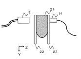
図2は、被検体情報取得装置の部分的な模式図である。本実施例の装置において、被検者の乳房を被検体として測定する際には、被検者を伏臥位にし、被検体21を2枚のプレート(圧迫プレート22と保持プレート23)で挟み込む。圧迫プレートと保持プレートとの距離は調整可能となっているため、被検体を圧迫保持する強度や、被検体の厚さ(薄さ)を制御できる。
FIG. 2 is a partial schematic diagram of the subject information acquiring apparatus. In the apparatus of this embodiment, when measuring the subject's breast as a subject, the subject is placed in a prone position and the subject 21 is sandwiched between two plates (the
探触子14は、被検体から発せられた超音波や光音響波を、被検体を保持した保持プレ
ートを介して受信する。探触子と保持プレートの間や保持プレートと被検体の間には、音響マッチング材を配置しても良い。探触子は保持プレートの面に沿ったXY方向において、機械的な移動走査が可能である。
The
図3は、探触子14の機械的走査を示す図である。上記の通り、この探触子は超音波用1Dアレイ探触子5と光音響波用2Dアレイ探触子6が一体化したものである。探触子は被検体21の上を、保持プレート23を介して、移動経路31に沿って移動する。
FIG. 3 is a diagram showing mechanical scanning of the
初めに、走査制御部12は、探触子を保持プレートの面に沿って水平方向(X方向)を右へ移動させる。探触子が右端部に至ったところで移動方向を垂直方向(Y方向)の下向きに変更する。探触子がY方向に所定の距離だけ移動すると、再度水平方向の左向きに移動させる。走査制御部がこのような探触子の機械走査を繰り返すことで、検査領域の全域が測定できる。
First, the
ここで、X方向の一回の走査により形成される領域をストライプと呼ぶ。装置は、被検体を複数のストライプに分割することで全体領域を測定する。画像再構成の際には、スプライトごとに画像再構成をしても良いし、複数または全部のスプライトをまとめて画像再構成の単位としても良い。あるいはスプライトにとらわれずに部分領域を設定しても構わない。
この例においては、ストライプの延伸する方向であるX方向を主走査方向、ストライプ間を移動する方向であるY方向を副走査方向と呼ぶことができる。また、ストライプ同士はY方向で重複していても構わない。
Here, a region formed by a single scan in the X direction is called a stripe. The apparatus measures the entire area by dividing the subject into a plurality of stripes. At the time of image reconstruction, image reconstruction may be performed for each sprite, or a plurality or all of the sprites may be combined as a unit for image reconstruction. Alternatively, the partial area may be set without being constrained by the sprite.
In this example, the X direction, which is the direction in which the stripes extend, can be referred to as the main scanning direction, and the Y direction, which is the direction to move between the stripes, can be referred to as the sub-scanning direction. The stripes may overlap in the Y direction.
なお、機械的走査における光照射と光音響波取得のタイミングは任意である。例えば探触子を間欠的に移動させ、停止したときに測定する方式(ステップアンドリピート)であっても良い。あるいは、探触子を連続的に移動させつつ測定する方式でも良い。いずれの方式であっても、探触子の位置や測定タイミングに応じた演算を行うことにより、被検体内を再構成できる。これにより、移動経路31上の各位置において繰り返しの画像を取得できる。
Note that the timing of light irradiation and photoacoustic wave acquisition in mechanical scanning is arbitrary. For example, a method of measuring when the probe is moved intermittently and stopped (step and repeat) may be used. Alternatively, the measurement may be performed while continuously moving the probe. In any method, the inside of the subject can be reconfigured by performing calculations according to the position of the probe and the measurement timing. Thereby, repeated images can be acquired at each position on the
(画像データの生成と表示)
図4は、探触子が移動経路31に沿って移動しながら、超音波画像となる2次元の断層スライス像を取得する時の走査手順を示したものである。断層スライス像は、探触子を間欠的に移動させた場合は停止のタイミングで出力され、探触子を連続的に移動させた場合は一定周期の間隔で出力される。取得した断層スライス像を並べることで、検査領域全体の3次元超音波画像を構成できる。
(Generation and display of image data)
FIG. 4 shows a scanning procedure when acquiring a two-dimensional tomographic slice image that becomes an ultrasonic image while the probe moves along the
図5は、被検体を保持プレートと圧迫プレートで挟み込んだ時の、被検体の形状を示す3面図である。図5A〜図5Cはそれぞれ、被検体を3方向からカメラ等の撮影手段で撮影した画像である。医療者などによる診断の際、この3面図にPAT画像や超音波画像を重畳表示することも可能である。なお、マーキング51は、病変位置を特定するために、操作者の指定などに応じて表示される。 FIG. 5 is a trihedral view showing the shape of the subject when the subject is sandwiched between the holding plate and the compression plate. 5A to 5C are images obtained by photographing the subject from three directions by photographing means such as a camera. At the time of diagnosis by a medical practitioner or the like, it is also possible to superimpose and display a PAT image or an ultrasonic image on this three-view drawing. The marking 51 is displayed according to an operator's designation or the like in order to specify a lesion position.
PATによって画像再構成された3次元画像データが存在すれば、表示制御部がボリュームレンダリング機能により3面スライス画像を抽出することで、被検体内部の任意の位置(X座標、Y座標、Z座標)を指定した3面スライス画像を表示できる。 If 3D image data reconstructed by PAT exists, the display control unit extracts a three-plane slice image by the volume rendering function, so that an arbitrary position (X coordinate, Y coordinate, Z coordinate) inside the subject can be obtained. ) Can be displayed.
一方、超音波による3次元画像データについては、探触子を走査している間であっても、取得した断層スライス像を並べることで、順次3次元での画像化が可能である。すなわち、保持プレートに沿ったXY面のCモード画像と、探触子の素子配列に沿ったYZ面の
断層スライス像(Bモード画像)と、XZ面にあたるエレベーション画像の3面スライス画像が抽出できる。
On the other hand, three-dimensional image data using ultrasonic waves can be sequentially imaged in three dimensions by arranging the acquired tomographic slice images even while the probe is being scanned. That is, a C-mode image of the XY plane along the holding plate, a tomographic slice image (B-mode image) of the YZ plane along the element arrangement of the probe, and a three-plane slice image of the elevation image corresponding to the XZ plane are extracted. it can.
この時、PATによる画像再構成では被検体全体(あるいは、被検体を分割した部分領域ごとに再構成する場合、その対象となる部分領域全体)の受信データが必要となる。そのため、領域全体の走査完了後に再構成処理を行って画像データを生成している。
一方、超音波による画像再構成では、探触子を走査し他領域について順次断層スライス像が得られる。そのため、探触子の走査が完了した領域の画像データが順次生成される。すなわち、PAT画像は全走査完了後に画像再構成を行って表示されることになるが、超音波画像は走査しながらのリアルタイム表示が可能である。
At this time, in the image reconstruction by PAT, the reception data of the entire subject (or the entire partial area as a target when the subject is reconstructed for each partial area) is required. For this reason, image data is generated by performing reconstruction processing after the entire region has been scanned.
On the other hand, in image reconstruction using ultrasound, a probe is scanned and tomographic slice images are sequentially obtained for other regions. Therefore, the image data of the area where the scanning of the probe is completed is sequentially generated. That is, the PAT image is displayed after image reconstruction after completion of all scanning, but the ultrasonic image can be displayed in real time while scanning.
図6Aおよび図6Bは、超音波画像を探触子の走査に合わせてリアルタイム表示した時の表示例である。それぞれの図において、深度ZのCモード画像が複数表示されている。これらの例では、探触子をX方向への走査に連れて、Z=10mm、15mm、20mmの深さにおけるCモード画像がディスプレイ上に表示されている。すなわち、光音響画像生成用のデータが取得されている期間にも、Cモード画像が表示されている。 6A and 6B are display examples when an ultrasonic image is displayed in real time in accordance with the scanning of the probe. In each figure, a plurality of C-mode images of depth Z are displayed. In these examples, as the probe is scanned in the X direction, C-mode images at depths of Z = 10 mm, 15 mm, and 20 mm are displayed on the display. That is, the C-mode image is also displayed during the period when the data for generating the photoacoustic image is acquired.
図6Aは、それぞれ10mm、15mm、20mmの深さに対応したCモード画像61、62、63を示す。探触子がX方向の走査位置64まで移動するに連れて、画像が順次生成されてディスプレイに表示される。そして、探触子がY方向に移動してストライプが変わった際には、画像をクリアして、次のストライプを新たに表示する。
FIG. 6A shows C-
図6Bは、それぞれ10mm、15mm、20mmの深さに対応したCモード画像65、66、67を示す。図6Bの方式では、Y方向が次のストライプに切り替わっても前の画像を表示しておくことで、被検体全体の画像を最終的に表示する。
この表示方式は、病変部69が深さ方向Zに広がっているときの形態情報を把握する場合に適したものである。この方式は、他モダリティで確認した病変部の形状と比較する場合に最も適している。
FIG. 6B shows C-
This display method is suitable for grasping morphological information when the
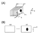
図7は、超音波画像を探触子の走査に合わせてリアルタイム表示した時の一例として、走査が行われている期間においても、走査位置XのBモード画像を連続表示した場合の図を示している。
図7Aは、探触子のX方向の走査位置に対して、X0からX7までの断層スライス像を示した図である。図7Bは、X0からX7までの断層スライス像をディスプレイ上に連続表示している図である。この時、各画像は同じ位置や異なる位置に連続表示する手法でも良く、指定したX方向の位置の画像を選択表示する手法でも良い。さらに双方の画像を同時に表示しても良い。
FIG. 7 is a diagram showing a case where a B-mode image at the scanning position X is continuously displayed even during the scanning period, as an example when the ultrasonic image is displayed in real time in accordance with the scanning of the probe. ing.
FIG. 7A is a diagram showing tomographic slice images X0 to X7 with respect to the scanning position of the probe in the X direction. FIG. 7B is a diagram in which tomographic slice images from X0 to X7 are continuously displayed on the display. At this time, each image may be continuously displayed at the same position or different positions, or a method of selectively displaying an image at a specified position in the X direction may be used. Furthermore, both images may be displayed simultaneously.
ここで、物体71は病変部を示す。各断層スライス像の表示を比較すると、物体71は、X0には写らないがX7には写っている。これは、探触子の走査位置によって超音波画像が変化することを示している。
この表示方式は、病変部が走査方向Xに広がっているときの形態情報を把握する場合に適したものである。この方式は、探触子の走査位置に対するリアルタイム画像を確認する時に適した方法である。
Here, the
This display method is suitable for grasping morphological information when a lesion is spreading in the scanning direction X. This method is suitable for confirming a real-time image with respect to the scanning position of the probe.
本実施例において各種の画像表示例を用いて示したように、本発明によれば、被検体に対して探触子をXY方向に走査しながら、超音波の画像データを順次表示させることが可能となる。その結果、超音波画像と光音響画像を共に使用する被検体情報取得装置において、光音響トモグラフィーの進行を待たずとも、リアルタイムに撮影状態(装置動作状態、撮影進行具合)が確認できるという効果が得られる。したがって使用者は画像を随時確
認しながら必要な操作を検討できるようになる。
As shown by various image display examples in the present embodiment, according to the present invention, ultrasonic image data can be sequentially displayed while scanning the probe in the X and Y directions with respect to the subject. It becomes possible. As a result, in the subject information acquisition apparatus that uses both the ultrasound image and the photoacoustic image, the imaging state (apparatus operating state, imaging progress) can be confirmed in real time without waiting for the progress of photoacoustic tomography. can get. Therefore, the user can examine necessary operations while checking images at any time.
<実施例2>
本実施例では、被検体に関心領域(ROI)を設定する被検体情報取得装置に本発明を適用する方法と効果を説明する。本実施例の装置は、使用者からの指示入力を受け付けて、被検体上にROIを設定する入力手段を有する。
<Example 2>
In this embodiment, a method and effect of applying the present invention to a subject information acquisition apparatus that sets a region of interest (ROI) in a subject will be described. The apparatus according to the present embodiment includes an input unit that receives an instruction input from a user and sets an ROI on a subject.
PATにより被検体21の画像データを取得する際に、他モダリティ(MRI、X線マンモグラフィ、超音波)の診断結果等から病変部71の位置XYを予め推定しておき、病変部周辺をROIに設定して測定を行うことが好適である。ROIを設定することで、被検体全体を測定する必要性が無い場合の測定時間の短縮や、必要な領域だけに狙いを定めた詳細画像データの生成が可能となる。
When acquiring image data of the subject 21 by PAT, the position XY of the
図8に、本実施例においてディスプレイ表示される画像を示す。図8Aは、探触子の走査位置を確認できるカメラ画像である。図8Bは、リアルタイムに生成されるCモード画像である。これらを同時に表示させることで、探触子の走査位置と病変部の相対位置を画面で確認できるようになる。 FIG. 8 shows an image displayed on the display in this embodiment. FIG. 8A is a camera image in which the scanning position of the probe can be confirmed. FIG. 8B is a C-mode image generated in real time. By displaying these simultaneously, the scanning position of the probe and the relative position of the lesion can be confirmed on the screen.
図8Aのカメラ画像において、範囲81は、関心領域(ROI)の初期設定範囲を示している。この設定により、開始点(X0、Y0)と終了点(X1、Y1)で規定される範囲からPATの画像データが取得される。
なお、ROIの位置や大きさは任意に変更可能である。またROIの形状は長方形に限られない。カメラ画像で被検体画像のマーキング位置を見ながら設定位置を確認することができる。ROIの位置は、使用者による座標指定やタッチペンでの特定など、任意の方法で決定できる。
In the camera image of FIG. 8A, a
Note that the position and size of the ROI can be arbitrarily changed. The shape of the ROI is not limited to a rectangle. The set position can be confirmed while viewing the marking position of the subject image on the camera image. The position of the ROI can be determined by an arbitrary method such as coordinate designation by the user or identification with a touch pen.
図8BのCモード画像において、領域82は、ストライプ単位でのROIの設定範囲を示している。この領域82は、カメラ画像におけるROIの設定範囲81が必要十分に含まれるように、ストライプ単位で設定される。領域82は、例えば、領域81と探触子のサイズや走査経路に関する情報に基づき自動的に決定できる。
In the C-mode image of FIG. 8B, an
ROIを設定する際には、被検体の表面にマーキング51を行って病変部71の位置を特定し、カメラ画像を見ながらROIの中心をその位置に合わせることになる。ところが、被検体を保持プレートと圧迫プレートで挟み込んだ時に被検体形状が変化して、マーキング位置が実際の病変部とずれてしまう場合がある。
When setting the ROI, marking 51 is performed on the surface of the subject to identify the position of the
しかし、PATにより再構成された画像は、画像化対象領域(この場合ROI)の全体を走査し終えてからでないと確認できない。したがって、位置ずれが起こった場合、再構成画像の一部が無駄になる、診断に必要な部分が画像化できない等の問題が起こる。なお、関心領域の設定は、マーキング位置に基づいて自動的に行われても良い。 However, an image reconstructed by PAT can only be confirmed after the entire imaging target area (in this case, ROI) has been scanned. Therefore, when a position shift occurs, problems such as a part of the reconstructed image being wasted and a part necessary for diagnosis cannot be imaged. Note that the region of interest may be automatically set based on the marking position.
そこで実施例1で示した装置を利用すれば、このような問題に対処できる。すなわちこの装置には、超音波送受信により得られたCモード画像が順次表示される。かかる画像を利用して病変部の正確な位置をリアルタイムで確認することにより、ROIの設定範囲が適切かどうかを随時判断できるようになる。そのため、使用者が設定範囲をリアルタイムに調整できる。 Therefore, such a problem can be dealt with by using the apparatus shown in the first embodiment. That is, this apparatus sequentially displays C-mode images obtained by ultrasonic transmission / reception. By checking the exact position of the lesion in real time using such an image, it is possible to determine at any time whether the ROI setting range is appropriate. Therefore, the user can adjust the setting range in real time.
図8Bは各ストライプ単位でのCモード画像を示しているが、上側に位置するストライプ83のCモード画像を表示した段階で病変部71の一部が表示されているので、ROIの設定範囲82が外れていることが確認できる。すなわちROIの設定範囲81が病変部
71から外れていることが、ストライプ83を観察することで明確となるので、次のストライプ84のデータを取得する前にROIの設定位置を変更して、ストライプ83のデータを再取得する必要が生じている。
FIG. 8B shows a C-mode image for each stripe unit, but since a part of the
図9に、ROIの開始点に関して設定範囲を調整した後の状態を示す。図9Aはカメラ画像、図9BはCモード画像である。範囲91は、カメラ画像(図9A)でのROI調整後の設定範囲を示している。この設定により、ROIの開始点が(X0、Y0)から(X2、Y2)に変更され、PATの画像データが再取得される。開始点の変更は、例えば、超音波画像を参照した使用者による、入力手段を用いた介入を受け付けることにより行われる。
FIG. 9 shows a state after the setting range is adjusted with respect to the ROI start point. 9A is a camera image, and FIG. 9B is a C-mode image. A
ROIの開始点が変更されたことで、図9BのCモード画像では、新たなROI領域92が設定され、ストライプ93も測定対象となる。すなわち、機能分布情報を生成するストライプが増加する。そこで探触子5は、Y方向の位置を変えずにストライプ93を再走査し、データを取得する。その時、変更されたROI領域92の全体に関してPATの画像データも同時に取得される。
By changing the ROI start point, a
図10に、ROIの終了点に関して設定範囲を調整した後の状態を示す。図10Aはカメラ画像、図10BはCモード画像である。範囲101は、カメラ画像(図10A)でのROI調整後の設定範囲を示している。この設定により、ROIの終了点が(X1、Y1)から(X3、Y3)に変更されている。
FIG. 10 shows a state after adjusting the setting range with respect to the ROI end point. FIG. 10A is a camera image, and FIG. 10B is a C-mode image. A
終了点の変更に伴い、Cモード画像(図10B)ではストライプ106におけるROIの範囲設定102が不要となる。すなわち、結果として光音響波のデータ取得が必要となるのはストライプ103、104、105に限定されるため、測定時間が短縮される。
As the end point is changed, the ROI range setting 102 in the
また本実施例では、病変部の形状をCモード画像で確認している。しかし、病変部が見つからなかった場合には、ROIの範囲設定を解除してPATの画像再構成をキャンセルするといった方法にも適用可能である。 In this embodiment, the shape of the lesion is confirmed with a C-mode image. However, when a lesion is not found, the present invention can also be applied to a method of canceling ROT range setting and canceling PAT image reconstruction.
本発明によれば、上記実施例で示したように、被検体の全領域に対しては超音波画像をリアルタイムに取得し、関心領域(ROI)に対してはPAT画像を取得するシステムにおいて、走査途中でもROIの調整が容易に実行可能となる。具体的には、プローブ走査中の超音波画像をリアルタイムに参照しながら、予め設定していたROIの測定条件を調整することが可能となる。 According to the present invention, as shown in the above embodiment, in the system for acquiring an ultrasonic image in real time for the entire region of the subject and acquiring a PAT image for the region of interest (ROI), Even during scanning, the ROI can be easily adjusted. Specifically, ROI measurement conditions set in advance can be adjusted while referring to an ultrasonic image during probe scanning in real time.
ここで調整する測定条件としては、設定範囲(サイズ、位置)だけでなく、ノイズを削減するための積算回数や、信号強度を調整するゲイン(TGC)などについても変更可能である。 As the measurement conditions to be adjusted here, not only the setting range (size, position) but also the number of integrations for reducing noise, the gain (TGC) for adjusting the signal intensity, and the like can be changed.
なお、上記いずれの実施例においても、被検体に対して探触子をXY方向に走査しながら、超音波の画像データを順次表示させることは可能である。したがって本発明は、光音響検出を行わず超音波の送受信のみにより被検体内情報を画像化する装置にも適用可能である。 In any of the above-described embodiments, it is possible to sequentially display ultrasonic image data while scanning the probe in the XY directions with respect to the subject. Therefore, the present invention is also applicable to an apparatus that images in-subject information by only transmitting and receiving ultrasonic waves without performing photoacoustic detection.
1:CPU,2:超音波送信部,3:超音波受信部,4:光音響波受信部,5:超音波探触子,6:光音響波探触子,9:画像処理部,10:表示制御部,11:ディスプレイ,12:走査制御部,13:機構部 1: CPU, 2: Ultrasonic transmitter, 3: Ultrasonic receiver, 4: Photoacoustic wave receiver, 5: Ultrasonic probe, 6: Photoacoustic wave probe, 9: Image processor, 10 : Display control unit, 11: Display, 12: Scanning control unit, 13: Mechanism unit
Claims (20)
前記受信手段を前記被検体に対して機械的に走査する走査手段と、
前記超音波を用いて前記被検体内の形態分布情報を生成するとともに、前記光音響波を用いて前記被検体内の機能分布情報を生成する処理手段と、
前記形態分布情報および前記機能分布情報を表示手段に表示させる制御を行う制御手段と、
前記被検体における関心領域の指定を受け付ける入力手段と、
を有し、
前記制御手段は、前記受信手段が前記被検体の少なくとも一部の領域からなる部分領域からの光音響波を受信して、前記処理手段が当該部分領域の機能分布情報を生成する期間に、前記処理手段が前記被検体の前記部分領域から反射した超音波に基づき生成した形態分布情報を、前記走査手段による前記部分領域内における前記受信手段の走査に伴い順次、前記表示手段に表示させる制御を行うものであり、
前記処理手段は、前記関心領域において、前記光音響波を用いた前記機能分布情報の生成を行うものであり、
前記入力手段は、前記制御手段が前記形態分布情報を順次、前記表示手段に表示させているときに、前記関心領域の変更を受け付けることが可能であり、
前記走査手段は、変更された前記関心領域に基づいて前記受信手段の経路を変更する
ことを特徴とする被検体情報取得装置。 Receiving means for receiving ultrasonic waves reflected by the subject after being transmitted to the subject and photoacoustic waves generated by the subject irradiated with light;
Scanning means for mechanically scanning the receiving means with respect to the subject;
Processing means for generating morphological distribution information in the subject using the ultrasound and generating functional distribution information in the subject using the photoacoustic wave;
Control means for controlling the display means to display the form distribution information and the function distribution information;
Input means for receiving designation of a region of interest in the subject;
Have
The control means receives a photoacoustic wave from a partial area consisting of at least a partial area of the subject, and the processing means generates functional distribution information of the partial area. Control for causing the display means to sequentially display the morphological distribution information generated based on the ultrasound reflected from the partial area of the subject by the processing means as the receiving means scans the partial area by the scanning means. What to do ,
Pre Symbol processing means, in the region of interest, which performs generation of the functional distribution information using the photoacoustic wave,
The input means can accept a change of the region of interest when the control means is sequentially displaying the morphological distribution information on the display means,
The subject information acquisition apparatus, wherein the scanning unit changes a path of the receiving unit based on the changed region of interest.
前記表示手段は、前記形態分布情報とともに、前記撮影手段により得られた画像を表示する
ことを特徴とする請求項1に記載の被検体情報取得装置。 It further has an imaging means for imaging the subject,
The object information acquiring apparatus according to claim 1, wherein the display unit displays an image obtained by the imaging unit together with the morphological distribution information.
ことを特徴とする請求項1または2に記載の被検体情報取得装置。 The subject information acquisition apparatus according to claim 1, wherein the region of interest is set based on a marking made on a surface of the subject.
ことを特徴とする請求項1ないし3のいずれか1項に記載の被検体情報取得装置。 The scanning means scans the receiving means in the main scanning direction to form stripes, and scans the receiving means in the sub-scanning direction to move between the stripes. 4. The subject information acquisition apparatus according to any one of items 3.
前記走査手段は、前記受信手段を前記保持手段に沿って機械的に走査する
ことを特徴とする請求項1ないし4のいずれか1項に記載の被検体情報取得装置。 It further has holding means for holding the subject,
The object information acquiring apparatus according to claim 1, wherein the scanning unit mechanically scans the receiving unit along the holding unit.
ことを特徴とする請求項5に記載の被検体情報取得装置。 The object information acquiring apparatus according to claim 5, wherein the processing unit displays a C-mode image along the holding unit for each depth as the morphological distribution information.
ことを特徴とする請求項1ないし7のいずれか1項に記載の被検体情報取得装置。 The said receiving means integrates the probe which receives the said ultrasonic wave, and the probe which receives the said photoacoustic wave, The one of Claim 1 thru | or 7 characterized by the above-mentioned. Subject information acquisition apparatus.
ことを特徴とする請求項1ないし7のいずれか1項に記載の被検体情報取得装置。 The object information acquiring apparatus according to claim 1, wherein the receiving unit uses a common element for receiving the ultrasonic wave and receiving the photoacoustic wave.
ことを特徴とする請求項1ないし9のいずれか1項に記載の被検体情報取得装置。 The object information acquiring apparatus according to claim 1, further comprising the display unit.
を有する被検体情報取得装置の制御方法であって、
前記受信手段が、前記被検体に送信されたのち前記被検体で反射した超音波を受信するステップと、
前記受信手段が、光を照射された前記被検体で発生した光音響波を受信するステップと、
前記処理手段が、前記超音波を用いて前記被検体内の形態分布情報を生成するステップと、
前記処理手段が、前記光音響波を用いて前記被検体内の機能分布情報を生成するステップと、
前記制御手段が、前記受信手段が前記被検体の少なくとも一部の領域からなる部分領域からの光音響波を受信して、前記処理手段が当該部分領域の機能分布情報を生成する期間に、前記処理手段が前記被検体の前記部分領域から反射した超音波に基づき生成した形態分布情報を、前記走査手段による前記部分領域内における前記受信手段の走査に伴い順次、前記表示手段に表示させる制御を行うステップと、
前記入力手段が、前記被検体における関心領域の指定を受け付けるステップと、
前記処理手段が、前記関心領域において、前記光音響波を用いた前記機能分布情報の生成を行うステップと、
前記入力手段が、前記制御手段が前記形態分布情報を順次、前記表示手段に表示させているときに、前記関心領域の変更を受け付けるステップと、
前記走査手段が、変更された前記関心領域に基づいて前記受信手段の経路を変更するステップと、
を有することを特徴とする被検体情報取得装置の制御方法。 A receiving means, a scanning means for mechanically scanning the receiving means with respect to the subject, a processing means, a control means for controlling the display means to display morphological distribution information and functional distribution information, an input means,
A method for controlling a subject information acquisition apparatus comprising:
Receiving the ultrasound reflected by the subject after being transmitted to the subject;
Receiving the photoacoustic wave generated by the subject irradiated with light; and
The processing means generates morphological distribution information in the subject using the ultrasound; and
The processing means generating functional distribution information in the subject using the photoacoustic wave;
The control means receives a photoacoustic wave from a partial area consisting of at least a partial area of the subject, and the processing means generates functional distribution information of the partial area. Control for causing the display means to sequentially display the morphological distribution information generated based on the ultrasound reflected from the partial area of the subject by the processing means as the receiving means scans the partial area by the scanning means. Steps to do,
The input means accepting designation of a region of interest in the subject;
The processing means generating the functional distribution information using the photoacoustic wave in the region of interest;
Receiving the change of the region of interest when the input means causes the control means to sequentially display the morphological distribution information on the display means;
The scanning means changing the path of the receiving means based on the changed region of interest;
A method for controlling a subject information acquiring apparatus, comprising:
前記表示手段が、前記形態分布情報とともに、前記撮影手段により得られた画像を表示するステップをさらに有する
ことを特徴とする請求項11に記載の被検体情報取得装置の制御方法。 The subject information acquisition apparatus further includes imaging means for imaging the subject,
The method for controlling an object information acquiring apparatus according to claim 11, wherein the display unit further includes a step of displaying an image obtained by the imaging unit together with the morphological distribution information.
ことを特徴とする請求項11または12に記載の被検体情報取得装置の制御方法。 The method of controlling an object information acquiring apparatus according to claim 11, wherein the region of interest is set based on a marking made on a surface of the object.
ことを特徴とする請求項11ないし13のいずれか1項に記載の被検体情報取得装置の制御方法。 The scanning means scans the receiving means in the main scanning direction to form stripes, and scans the receiving means in the sub-scanning direction to move between the stripes. 14. A method for controlling an object information acquiring apparatus according to any one of items 13 to 13.
前記走査手段は、前記受信手段を前記保持手段に沿って機械的に走査する
ことを特徴とする請求項11ないし14のいずれか1項に記載の被検体情報取得装置の制御方法。 The subject information acquisition apparatus further includes holding means for holding the subject,
15. The method for controlling an object information acquiring apparatus according to claim 11, wherein the scanning unit mechanically scans the receiving unit along the holding unit.
ことを特徴とする請求項15に記載の被検体情報取得装置の制御方法。 The method for controlling an object information acquiring apparatus according to claim 15, wherein the processing unit displays a C-mode image along the holding unit for each depth as the form distribution information.
ことを特徴とする請求項15に記載の被検体情報取得装置の制御方法。 The method for controlling an object information acquiring apparatus according to claim 15, wherein the processing unit displays a B-mode image for each scanning position of the receiving unit as the form distribution information.
ことを特徴とする請求項11ないし17のいずれか1項に記載の被検体情報取得装置の制御方法。 The said receiving means is what integrated the probe which receives the said ultrasonic wave, and the probe which receives the said photoacoustic wave, The any one of Claim 11 thru | or 17 characterized by the above-mentioned. A method for controlling an object information acquiring apparatus.
ことを特徴とする請求項11ないし17のいずれか1項に記載の被検体情報取得装置の制御方法。 18. The object information acquiring apparatus according to claim 11, wherein the receiving unit uses a common element for receiving the ultrasonic wave and receiving the photoacoustic wave. Control method.
ことを特徴とする請求項11ないし19のいずれか1項に記載の被検体情報取得装置の制御方法。 The method for controlling an object information acquiring apparatus according to claim 11, wherein the object information acquiring apparatus further includes the display unit.
Priority Applications (4)
| Application Number | Priority Date | Filing Date | Title |
|---|---|---|---|
| JP2013199836A JP6253323B2 (en) | 2013-09-26 | 2013-09-26 | Subject information acquisition apparatus and control method thereof |
| EP14181957.3A EP2853917B1 (en) | 2013-09-26 | 2014-08-22 | Photoacoustic and ultrasound echo imaging apparatus and method for controlling same |
| US14/482,032 US20150087984A1 (en) | 2013-09-26 | 2014-09-10 | Object information acquiring apparatus and method for controlling same |
| CN201410490297.4A CN104510495B (en) | 2013-09-26 | 2014-09-23 | Subject information acquisition device and its control method |
Applications Claiming Priority (1)
| Application Number | Priority Date | Filing Date | Title |
|---|---|---|---|
| JP2013199836A JP6253323B2 (en) | 2013-09-26 | 2013-09-26 | Subject information acquisition apparatus and control method thereof |
Publications (3)
| Publication Number | Publication Date |
|---|---|
| JP2015065975A JP2015065975A (en) | 2015-04-13 |
| JP2015065975A5 JP2015065975A5 (en) | 2016-11-10 |
| JP6253323B2 true JP6253323B2 (en) | 2017-12-27 |
Family
ID=51492162
Family Applications (1)
| Application Number | Title | Priority Date | Filing Date |
|---|---|---|---|
| JP2013199836A Active JP6253323B2 (en) | 2013-09-26 | 2013-09-26 | Subject information acquisition apparatus and control method thereof |
Country Status (4)
| Country | Link |
|---|---|
| US (1) | US20150087984A1 (en) |
| EP (1) | EP2853917B1 (en) |
| JP (1) | JP6253323B2 (en) |
| CN (1) | CN104510495B (en) |
Families Citing this family (12)
| Publication number | Priority date | Publication date | Assignee | Title |
|---|---|---|---|---|
| CN105877780B (en) * | 2015-08-25 | 2019-05-31 | 上海深博医疗器械有限公司 | Fully-automatic ultrasonic scanner and scanning detection method |
| JP6907193B2 (en) * | 2015-09-10 | 2021-07-21 | コーニンクレッカ フィリップス エヌ ヴェKoninklijke Philips N.V. | Ultrasonic system with wide depth and detailed view |
| JP2017140093A (en) * | 2016-02-08 | 2017-08-17 | キヤノン株式会社 | Subject information acquisition device |
| WO2017167762A1 (en) | 2016-03-30 | 2017-10-05 | Koninklijke Philips N.V. | Phased array intravascular devices, systems, and methods utilizing photoacoustic and ultrasound techniques |
| WO2017205386A1 (en) * | 2016-05-27 | 2017-11-30 | Hologic, Inc. | Synchronized surface and internal tumor detection |
| WO2018008661A1 (en) * | 2016-07-08 | 2018-01-11 | キヤノン株式会社 | Control device, control method, control system, and program |
| CN106361372A (en) * | 2016-09-22 | 2017-02-01 | 华南理工大学 | Method for planning intelligent scanning path of ultrasonic probe |
| US20180146860A1 (en) * | 2016-11-25 | 2018-05-31 | Canon Kabushiki Kaisha | Photoacoustic apparatus, information processing method, and non-transitory storage medium storing program |
| JP6929048B2 (en) | 2016-11-30 | 2021-09-01 | キヤノン株式会社 | Display control device, display method, and program |
| CN108113650A (en) * | 2016-11-30 | 2018-06-05 | 佳能株式会社 | Display control unit, display control method and storage medium |
| WO2021166094A1 (en) * | 2020-02-19 | 2021-08-26 | TCC Media Lab株式会社 | Marking system for medical image, and marking assist device |
| CN112075957B (en) * | 2020-07-27 | 2022-05-17 | 深圳瀚维智能医疗科技有限公司 | Mammary gland circular scanning track planning method and device and computer readable storage medium |
Family Cites Families (10)
| Publication number | Priority date | Publication date | Assignee | Title |
|---|---|---|---|---|
| US7556602B2 (en) * | 2000-11-24 | 2009-07-07 | U-Systems, Inc. | Breast cancer screening with adjunctive ultrasound mammography |
| JP4643153B2 (en) * | 2004-02-06 | 2011-03-02 | 株式会社東芝 | Non-invasive biological information imaging device |
| CN102292029B (en) * | 2008-07-18 | 2014-11-05 | 罗切斯特大学 | Low-cost device for C-scan photoacoustic imaging |
| JP5393256B2 (en) | 2009-05-25 | 2014-01-22 | キヤノン株式会社 | Ultrasonic device |
| TWI405560B (en) * | 2009-12-15 | 2013-08-21 | Nat Univ Tsing Hua | Imaging method and system for microcalcification in tissue |
| JP5448785B2 (en) * | 2009-12-18 | 2014-03-19 | キヤノン株式会社 | Measuring device, movement control method, and program |
| JP5655021B2 (en) * | 2011-03-29 | 2015-01-14 | 富士フイルム株式会社 | Photoacoustic imaging method and apparatus |
| JP5984541B2 (en) * | 2011-08-08 | 2016-09-06 | キヤノン株式会社 | Subject information acquisition apparatus, subject information acquisition system, display control method, display method, and program |
| JP5984542B2 (en) * | 2011-08-08 | 2016-09-06 | キヤノン株式会社 | Subject information acquisition apparatus, subject information acquisition system, display control method, display method, and program |
| JP5843570B2 (en) * | 2011-10-31 | 2016-01-13 | キヤノン株式会社 | SUBJECT INFORMATION ACQUISITION DEVICE, CONTROL METHOD FOR THE DEVICE, AND PROGRAM |
-
2013
- 2013-09-26 JP JP2013199836A patent/JP6253323B2/en active Active
-
2014
- 2014-08-22 EP EP14181957.3A patent/EP2853917B1/en active Active
- 2014-09-10 US US14/482,032 patent/US20150087984A1/en not_active Abandoned
- 2014-09-23 CN CN201410490297.4A patent/CN104510495B/en active Active
Also Published As
| Publication number | Publication date |
|---|---|
| CN104510495A (en) | 2015-04-15 |
| EP2853917B1 (en) | 2020-01-15 |
| US20150087984A1 (en) | 2015-03-26 |
| EP2853917A1 (en) | 2015-04-01 |
| JP2015065975A (en) | 2015-04-13 |
| CN104510495B (en) | 2018-12-07 |
Similar Documents
| Publication | Publication Date | Title |
|---|---|---|
| JP6253323B2 (en) | Subject information acquisition apparatus and control method thereof | |
| JP6192297B2 (en) | SUBJECT INFORMATION ACQUISITION DEVICE, DISPLAY CONTROL METHOD, AND PROGRAM | |
| JP5917037B2 (en) | Subject information acquisition apparatus and subject information acquisition method | |
| JP5984547B2 (en) | Subject information acquisition apparatus and control method thereof | |
| JP5496031B2 (en) | Acoustic wave signal processing apparatus, control method thereof, and control program | |
| KR101984824B1 (en) | Method and apparatus for analyzing elastography of tissue using ultrasound | |
| US20130116536A1 (en) | Acoustic wave acquiring apparatus and acoustic wave acquiring method | |
| JP6498036B2 (en) | Photoacoustic apparatus, signal processing method, and program | |
| JP6071260B2 (en) | Subject information acquisition apparatus and information processing method | |
| JP5950540B2 (en) | SUBJECT INFORMATION ACQUISITION DEVICE, CONTROL METHOD FOR THE DEVICE, AND PROGRAM | |
| US20160150973A1 (en) | Subject information acquisition apparatus | |
| JP2012024227A (en) | Image information acquiring apparatus, image information acquiring method and image information acquiring program | |
| JP5843570B2 (en) | SUBJECT INFORMATION ACQUISITION DEVICE, CONTROL METHOD FOR THE DEVICE, AND PROGRAM | |
| JP5847454B2 (en) | Subject information acquisition apparatus, display control method, and program | |
| JP6742745B2 (en) | Information acquisition device and display method | |
| JP6656229B2 (en) | Photoacoustic device | |
| JP6234518B2 (en) | Information processing apparatus and information processing method | |
| EP3329843B1 (en) | Display control apparatus, display control method, and program | |
| JP6072206B2 (en) | SUBJECT INFORMATION ACQUISITION DEVICE AND DISPLAY METHOD | |
| JP2017164222A (en) | Processing device and processing method | |
| JP2018012027A (en) | Structure of recorded data | |
| JP6625182B2 (en) | Information processing apparatus, information processing method and program | |
| JP2018192309A (en) | Information processing device, information processing method, and program | |
| JP2019000387A (en) | Information processing apparatus, information processing method, and program | |
| JP6400068B2 (en) | Information processing apparatus and information processing method |
Legal Events
| Date | Code | Title | Description |
|---|---|---|---|
| A521 | Request for written amendment filed |
Free format text: JAPANESE INTERMEDIATE CODE: A523 Effective date: 20160923 |
|
| A621 | Written request for application examination |
Free format text: JAPANESE INTERMEDIATE CODE: A621 Effective date: 20160923 |
|
| A977 | Report on retrieval |
Free format text: JAPANESE INTERMEDIATE CODE: A971007 Effective date: 20170517 |
|
| A131 | Notification of reasons for refusal |
Free format text: JAPANESE INTERMEDIATE CODE: A131 Effective date: 20170704 |
|
| A521 | Request for written amendment filed |
Free format text: JAPANESE INTERMEDIATE CODE: A523 Effective date: 20170831 |
|
| A131 | Notification of reasons for refusal |
Free format text: JAPANESE INTERMEDIATE CODE: A131 Effective date: 20170912 |
|
| A521 | Request for written amendment filed |
Free format text: JAPANESE INTERMEDIATE CODE: A523 Effective date: 20170922 |
|
| TRDD | Decision of grant or rejection written | ||
| A01 | Written decision to grant a patent or to grant a registration (utility model) |
Free format text: JAPANESE INTERMEDIATE CODE: A01 Effective date: 20171031 |
|
| A61 | First payment of annual fees (during grant procedure) |
Free format text: JAPANESE INTERMEDIATE CODE: A61 Effective date: 20171128 |
|
| R151 | Written notification of patent or utility model registration |
Ref document number: 6253323 Country of ref document: JP Free format text: JAPANESE INTERMEDIATE CODE: R151 |