JP6508867B2 - Object information acquisition apparatus and control method therefor - Google Patents
Object information acquisition apparatus and control method therefor Download PDFInfo
- Publication number
- JP6508867B2 JP6508867B2 JP2013073462A JP2013073462A JP6508867B2 JP 6508867 B2 JP6508867 B2 JP 6508867B2 JP 2013073462 A JP2013073462 A JP 2013073462A JP 2013073462 A JP2013073462 A JP 2013073462A JP 6508867 B2 JP6508867 B2 JP 6508867B2
- Authority
- JP
- Japan
- Prior art keywords
- probe
- receiving elements
- light source
- object information
- light
- Prior art date
- Legal status (The legal status is an assumption and is not a legal conclusion. Google has not performed a legal analysis and makes no representation as to the accuracy of the status listed.)
- Expired - Fee Related
Links
Images


Classifications
-
- A—HUMAN NECESSITIES
- A61—MEDICAL OR VETERINARY SCIENCE; HYGIENE
- A61B—DIAGNOSIS; SURGERY; IDENTIFICATION
- A61B5/00—Measuring for diagnostic purposes; Identification of persons
- A61B5/0093—Detecting, measuring or recording by applying one single type of energy and measuring its conversion into another type of energy
- A61B5/0095—Detecting, measuring or recording by applying one single type of energy and measuring its conversion into another type of energy by applying light and detecting acoustic waves, i.e. photoacoustic measurements
-
- G—PHYSICS
- G01—MEASURING; TESTING
- G01N—INVESTIGATING OR ANALYSING MATERIALS BY DETERMINING THEIR CHEMICAL OR PHYSICAL PROPERTIES
- G01N29/00—Investigating or analysing materials by the use of ultrasonic, sonic or infrasonic waves; Visualisation of the interior of objects by transmitting ultrasonic or sonic waves through the object
- G01N29/22—Details, e.g. general constructional or apparatus details
Description
本発明は、被検体情報取得装置およびその制御方法に関する。 The present invention relates to an object information acquisition apparatus and a control method thereof.
光音響イメージング法は、パルスレーザなどの光を被検体に照射し、熱膨張によって発生する光音響波を検出して被検体内部の3次元構造を画像化する方法である。光の波長を変化させることによって、血液中のヘモグロビンやグルコースなど、その波長の光を特に吸収する物質の分布を画像化できる。そのため、腫瘍に特徴的な新生血管を非侵襲で検出できるので、乳がんの早期発見の手段として注目されている。 The photoacoustic imaging method is a method of irradiating a subject with light such as a pulse laser, detecting a photoacoustic wave generated by thermal expansion, and imaging a three-dimensional structure inside the subject. By varying the wavelength of light, one can image the distribution of substances that specifically absorb light of that wavelength, such as hemoglobin and glucose in blood. Therefore, it can be noninvasively detected as a neovasculature characteristic of a tumor, and is thus attracting attention as a means for early detection of breast cancer.
従来、光音響イメージング法の具体的な手順は、例えば特許文献1において次のように開示されている。
(手順1)音響波を電気信号に変換する受信素子が2次元配列されたプローブ(2次元プローブ)を被検体表面に配置し、被検体に単パルスの電磁エネルギーを照射する。
(手順2)電磁エネルギーの照射直後から、各受信素子の受信信号をサンプリングして記憶する。
Conventionally, the specific procedure of the photoacoustic imaging method is disclosed, for example, in
(Procedure 1) A probe (two-dimensional probe) in which receiving elements for converting acoustic waves into electric signals are two-dimensionally arrayed is disposed on the surface of a subject, and a single pulse of electromagnetic energy is irradiated to the subject.
(Procedure 2) The received signal of each receiving element is sampled and stored immediately after irradiation of electromagnetic energy.
(手順3)音響波が、被検体内の注目点から各受信素子の位置に達するまでの遅れ時間を計算し、遅れ時間に対応する受信信号を加算して注目点の画像データの強度とする。
(手順4)画像化する注目点ごとに手順3を繰り返す。
(Procedure 3) The delay time until the acoustic wave reaches the position of each receiving element from the focus point in the subject is calculated, and the received signal corresponding to the delay time is added to obtain the strength of the image data of the focus point. .
(Step 4) Repeat
また、特許文献2は、光音響画像と通常の超音波エコー画像の双方を、共通の、受信素子が1次元配列されたプローブ(1次元プローブ)を用いて再構成する方法を開示している。この1次元プローブによって広い範囲の3次元画像を再構成するためには、プローブを、受信素子の配列方向とは直交する方向に機械的に移動させる必要がある。
Further,
ここで、光音響イメージング法を用いた3次元再構成画像の品質を向上させるためには、細かい間隔で光音響波を受信し、その光音響波に基づく光音響信号を用いて3次元画像を再構成することが効果的であると知られている。 Here, in order to improve the quality of a three-dimensional reconstructed image using the photoacoustic imaging method, photoacoustic waves are received at fine intervals, and a three-dimensional image is generated using a photoacoustic signal based on the photoacoustic waves. Reconstitution is known to be effective.
本発明は上記実情に鑑みてなされたものであり、その目的は、光音響イメージングにおいて、結果的に受信素子の配列間隔よりも細かい間隔で光音響波を取得するための技術を提供することである。 The present invention has been made in view of the above-described circumstances, and an object thereof is to provide a technique for obtaining photoacoustic waves at intervals finer than the arrangement interval of receiving elements in photoacoustic imaging. is there.
本発明は、以下の構成を採用する。すなわち、
繰返し周期ΔTで発光する光源と、
前記光源からの光を照射された被検体から発生する音響波を受信して電気信号に変換する複数の受信素子が第1の方向に配列されたプローブと、
前記プローブを前記第1の方向に移動させる移動手段と、
前記光源および前記移動手段を制御する制御手段と、
を有し、
nを1以上の整数、kを2以上の整数、dを前記受信素子の配列間隔としたとき、前記制御手段は、前記プローブを前記第1の方向に、(n+1/k)×d/ΔTまたは(n−1/k)×d/ΔTで表現される速度で連続移動させながら、前記プローブが前記受信素子の配列間隔dの(n+1/k)倍または(n−1/k)倍の距離を移動するごとに、前記光源から光が照射されるように制御を行う
ことを特徴とする被検体情報取得装置である。
本発明はまた、以下の構成を採用する。すなわち、
繰返し周期ΔTで発光する光源と、複数の受信素子が第1の方向に配列されたプローブと、前記プローブを前記第1の方向に移動させる移動手段と、
を有する被検体情報取得装置の制御方法であって、
前記複数の受信素子が、前記光源からの光を照射された被検体から発生する音響波を受信して電気信号に変換する受信ステップを有し、
nを1以上の整数、kを2以上の整数、dを前記受信素子の配列間隔としたとき、前記受信ステップにおいて、前記プローブを前記第1の方向に、(n+1/k)×d/ΔTまたは(n−1/k)×d/ΔTで表現される速度で連続移動させながら、前記プローブが前記受信素子の配列間隔dの(n+1/k)倍または(n−1/k)倍の距離を移動するごとに、前記光源から光が照射されるように制御を行う
ことを特徴とする被検体情報取得装置の制御方法である。
The present invention adopts the following configuration. That is,
A light source emitting light with a repetition period ΔT;
A probe in which a plurality of receiving elements for receiving an acoustic wave generated from a subject irradiated with light from the light source and converting it into an electric signal are arranged in a first direction;
Moving means for moving the probe in the first direction;
Control means for controlling the light source and the moving means;
Have
When n is an integer of 1 or more, k is an integer of 2 or more, and d is an arrangement interval of the receiving elements, the control means sets (n + 1 / k) × d / ΔT in the first direction. Alternatively, while continuously moving at a speed represented by (n-1 / k) × d / ΔT, the probe is (n + 1 / k) or (n-1 / k) times the arrangement interval d of the receiving elements The object information acquiring apparatus according to the present invention is controlled to emit light from the light source each time the distance is moved.
The present invention also adopts the following configuration. That is,
A light source emitting light with a repetition period ΔT, a probe in which a plurality of receiving elements are arranged in a first direction, and moving means for moving the probe in the first direction;
A control method of a subject information acquisition apparatus having
The plurality of receiving elements have a receiving step of receiving light from the light source and receiving an acoustic wave generated from the object and converting the light into an electrical signal.
In the receiving step, when n is an integer of 1 or more, k is an integer of 2 or more, and d is an arrangement interval of the receiving elements, in the receiving step, the probe is (n + 1 / k) × d / ΔT in the first direction. Alternatively, while continuously moving at a speed represented by (n-1 / k) × d / ΔT, the probe is (n + 1 / k) or (n-1 / k) times the arrangement interval d of the receiving elements It is a control method of a subject information acquisition apparatus characterized by performing control so that light may be emitted from the light source each time the distance is moved.
本発明によれば、光音響イメージングにおいて、結果的に受信素子の配列間隔よりも細かい間隔で光音響波を取得するための技術を提供できる。 According to the present invention, in photoacoustic imaging, it is possible to provide a technique for acquiring photoacoustic waves at intervals finer than the arrangement interval of receiving elements.
以下に図面を参照しつつ、本発明の実施形態を詳しく説明する。ただし、以下に記載されている詳細な計算式、計算手順などは、発明が適用される装置の構成や各種条件により適宜変更されるべきものであり、この発明の範囲を以下の記載に限定する趣旨のものではない。 Hereinafter, embodiments of the present invention will be described in detail with reference to the drawings. However, the detailed calculation formulas, calculation procedures, and the like described below should be appropriately changed depending on the configuration of the apparatus to which the invention is applied and various conditions, and the scope of the present invention is limited to the following description. It is not for the purpose.
本発明の被検体情報取得装置は、被検体に光(電磁波)を照射したときに、光音響効果により被検体内で発生し伝播した音響波を受信して、被検体情報を画像データとして取得する装置である。被検体情報取得装置は、被検体内を画像化する光音響イメージング装置として捉えることもできる。このとき取得される被検体情報とは、光照射によって生じた音響波の発生源分布、被検体内の初期音圧分布、あるいは初期音圧分布から導かれる光エネルギー吸収密度分布や吸収係数分布、組織を構成する物質の濃度分布を示す。組織を構成する物質とは、例えば、酸素飽和度分布や酸化・還元ヘモグロビン濃度分布などの血液成分、あるいは脂肪、コラーゲン、水分などである。 The subject information acquiring apparatus according to the present invention receives an acoustic wave generated and propagated in the subject by the photoacoustic effect when the subject is irradiated with light (electromagnetic wave), and acquires subject information as image data. Device. The subject information acquisition apparatus can also be regarded as a photoacoustic imaging apparatus for imaging the inside of a subject. The object information acquired at this time includes the source distribution of acoustic waves generated by light irradiation, the initial sound pressure distribution in the object, or the light energy absorption density distribution or absorption coefficient distribution derived from the initial sound pressure distribution, The concentration distribution of the substance which comprises a structure | tissue is shown. The substance constituting the tissue is, for example, a blood component such as oxygen saturation distribution or oxygenated / reduced hemoglobin concentration distribution, or fat, collagen, water or the like.
本発明はまた、被検体に超音波を送信し、被検体内での反射波(超音波エコー)を受信して画像データを生成する超音波装置にも適用できる。この場合の被検体情報は、音響インピーダンスの違いを示す。 The present invention is also applicable to an ultrasonic apparatus that transmits ultrasonic waves to a subject, receives reflected waves (ultrasound echoes) in the subject, and generates image data. The subject information in this case indicates the difference in acoustic impedance.
本発明でいう音響波とは、典型的には超音波であり、音波、音響波と呼ばれる弾性波を含む。光音響効果により発生した音響波のことを、光音響波または光超音波と呼ぶ。本発明の装置は、プローブ等の音響波検出器によって被検体内で発生又は反射して伝播した音響波を受信する。
以下の記載では、このような光音響波に由来する電気信号を、光音響信号とも呼ぶ。光音響信号は、プローブの受信素子により光音響波から変換されたアナログ信号や、アナログ信号に増幅やデジタル変換を施して得られたデジタル信号を含む概念である。光音響信号を取得すると言った場合、被検体に光を照射し、発生した光音響波をデジタル信号としてメモリ等に入力することを指す。
The acoustic wave referred to in the present invention is typically an ultrasonic wave, and includes acoustic waves and elastic waves called acoustic waves. The acoustic wave generated by the photoacoustic effect is called a photoacoustic wave or an optical ultrasonic wave. The apparatus of the present invention receives an acoustic wave generated or reflected and propagated in a subject by an acoustic wave detector such as a probe.
In the following description, an electrical signal derived from such a photoacoustic wave is also referred to as a photoacoustic signal. The photoacoustic signal is a concept including an analog signal converted from the photoacoustic wave by the receiving element of the probe, and a digital signal obtained by performing amplification and digital conversion on the analog signal. When it is said that a photoacoustic signal is to be acquired, it refers to irradiating a subject with light and inputting the generated photoacoustic wave as a digital signal to a memory or the like.
(画像品質向上の手法)
上述したように、光音響イメージングによる3次元再構成画像の品質を向上させる方法として、結果的に、2次元プローブにおける受信素子の配列間隔よりも細かい間隔で光音響信号を取得し、その光音響信号を用いて3次元画像を再構成することがある。以下に、
配列間隔dの1/4の間隔で信号取得する二つの方法を検討する。
(Method of image quality improvement)
As described above, as a method of improving the quality of a three-dimensional reconstructed image by photoacoustic imaging, as a result, photoacoustic signals are acquired at intervals finer than the arrangement interval of receiving elements in a two-dimensional probe, and the photoacoustic Signals may be used to reconstruct a three-dimensional image. less than,
Consider two methods of acquiring signals at an interval of 1⁄4 of the array interval d.
第1の方法は、細かいピッチで光音響信号を取得する第1のステップと、プローブを大きく移動させる第2のステップとを交互に繰り返すことである。第1のステップでは、プローブをd/4ずつ細かく移動させながら、各位置で1回ずつ、すなわち合計で4回、光音響信号を取得する。第2のステップでは、プローブをプローブの幅だけ移動させる。
このようにすれば、プローブの幅より広い検査領域において、通常の4倍の密度で光音響信号を取得できる。しかし、この方法では、第1のステップと第2のステップとでプローブを移動する速度が大きく異なるため、移動速度が頻繁に切り替わる。従って、プローブの制御が困難であり、高速での信号取得は難しい。
The first method is to alternately repeat the first step of acquiring the photoacoustic signal with a fine pitch and the second step of moving the probe widely. In the first step, the photoacoustic signal is acquired once at each position, that is, four times in total while moving the probe finely by d / 4. In the second step, the probe is moved by the width of the probe.
In this way, the photoacoustic signal can be acquired at a density four times the normal density in the inspection area wider than the width of the probe. However, in this method, the moving speed is frequently switched because the moving speed of the probe in the first step and the second step is largely different. Therefore, control of the probe is difficult and signal acquisition at high speed is difficult.
第2の方法では、検査領域全体の機械走査を4回繰り返す。その際、各回の機械走査の間では、光音響信号の受信位置がd/4ずつずれるようにする。これは例えば、測定開始時のプローブの位置をd/4ずつずらすことで実現できる。それぞれの機械走査においては、プローブが当該プローブの幅だけ移動するごとに、光音響信号を1回取得する。
このようにすれば、プローブを等速移動しながら高速に信号取得できる。しかしこの場合、プローブの折り返しが必要になるなどの理由から、測定全体に要する時間は長くなってしまう。また、d/4だけずれた隣接位置の光音響信号を取得するタイミングが大きく異なるので、生体などの時間的に変動する被検体に関しては、再構成画像の精度が劣化するという問題がある。
In the second method, mechanical scanning of the entire inspection area is repeated four times. At this time, the receiving position of the photoacoustic signal is shifted by d / 4 during each mechanical scanning. This can be realized, for example, by shifting the position of the probe at the start of measurement by d / 4. In each mechanical scan, a photoacoustic signal is acquired once each time the probe moves by the width of the probe.
In this way, it is possible to obtain a signal at high speed while moving the probe at a constant speed. However, in this case, the time required for the entire measurement becomes long because the probe needs to be folded. In addition, since the timings of acquiring the photoacoustic signals at the adjacent positions shifted by d / 4 are largely different, there is a problem that the accuracy of the reconstructed image is deteriorated with respect to a temporally varying object such as a living body.
(本発明のプローブの構成と走査)
本発明では、等間隔に配列された受信素子を含むプローブを、被検体に対して素子の配列方向に連続移動させる。そしてプローブは、連続移動しながら光音響波を受信して光音響信号を取得する。この信号を元に被検体内部の3次元画像が生成される。
なお、前述の特許文献2においても、1次元プローブの連続移動を行っていると推察される。しかし、その移動方向は受信素子の配列方向と直交した方向である点が、本発明と異なる。
(Configuration and scanning of the probe of the present invention)
In the present invention, the probe including the receiving elements arranged at equal intervals is continuously moved in the arrangement direction of the elements with respect to the subject. Then, the probe receives the photoacoustic wave while continuously moving and acquires a photoacoustic signal. Based on this signal, a three-dimensional image of the inside of the subject is generated.
In addition, also in the above-mentioned
プローブが連続移動しながら光音響波を受信する場合、受信中にプローブの位置が移動してしまうという問題がある。しかし、光音響波の受信は、光照射後のたかだか50〜100μs程度という、極めて短時間に行われる。一方、高出力のパルスレーザの繰り返し周期は、通常100ms程度の遅い周期に制限される。したがって、受信素子は遅い照射周期にあわせて低速で移動せざるを得ない。そのため、プローブが連続移動しながら光音響波取得する場合であっても、プローブが停止して光音響波取得する場合と、実効的にほとんど位置の差は生じない。
本発明のように、プローブが連続移動しながら光音響波を受信することによって、プローブの移動制御が容易となる上、位置決めのための時間を省略できるので、光音響信号を高速に取得できる。
When the probe moves continuously while receiving a photoacoustic wave, there is a problem that the position of the probe moves during reception. However, the photoacoustic wave is received in an extremely short time of about 50 to 100 μs after light irradiation. On the other hand, the repetition period of the high power pulsed laser is usually limited to a slow period of about 100 ms. Therefore, the receiving element has to move at low speed in accordance with the slow irradiation cycle. Therefore, even when the photoacoustic wave is acquired while the probe moves continuously, there is practically no difference in position from when the probe is stopped and the photoacoustic wave is acquired.
As in the present invention, by receiving the photoacoustic wave while the probe moves continuously, movement control of the probe becomes easy and time for positioning can be omitted, so that the photoacoustic signal can be acquired at high speed.
<実施例1>
図1は、光音響イメージング装置の全体構成である。光音響イメージング装置は、保持板2aおよび2b、移動台3aおよび3b、パルスレーザ光源4、プローブ8、計算機11、レーザ光源制御回路13、移動台制御回路14、AD変換回路15、記憶回路16、画像再構成回路17、表示装置18を含む。測定対象は、保持板2a、2bによって保持される被検体1である。被検体1の中には、ヘモグロビンのような光吸収体である、検出対象6が含まれている。移動台3a上にはパルスレーザ光源4が移動可能に設置される。なお、パルスレーザ光源4を移動させるのではなく、光学系により導かれた光が出射する出射部位を移動させるようにしても構わない。移動台3b上にはプローブ8が移動可能に設置される。
Example 1
FIG. 1 is an entire configuration of the photoacoustic imaging apparatus. The photoacoustic imaging apparatus includes holding
パルスレーザ光源4から保持板2aを介して被検体1に照射光5が照射されると、検出対象6が光エネルギーを吸収して膨張し、音響波7(光音響波)が発生する。音響波7の一部は保持板3bを介してプローブ8の受信素子によって受信され、電気信号(光音響信号)に変換される。検出対象6が被検体内部に複数個あれば、それぞれに起因する音響波が重畳されて、プローブ8により受信される。
When the
プローブ8の各受信素子で受信された信号は、いったん記憶回路に記憶される。そして、記憶された受信信号を元に被検体内部の検出対象の分布が3次元画像として再構成される。再構成処理には様々な既知の方法(例えば整相加算法)を利用できる。
被検体がプローブの受信素子配列領域よりも大きい場合には、移動台3aおよび3bによって、パルスレーザ光源4とプローブ8とを同期を取って移動させ、各位置で光音響信号を取得する。この場合、光音響信号の取得ごとに部分的な3次元画像を再構成しても良いし、光音響信号を記憶回路に蓄積しておき、測定対象の全域から光音響信号を取得したのち画像再構成しても良い。
The signal received by each receiving element of the
When the object is larger than the receiving element array area of the probe, the pulse
計算機11は装置全体の制御装置である。計算機11は移動台制御回路14に起動指令を出すと同時にレーザ光源制御回路13を起動する。移動台制御回路14とレーザ光源制御回路13は、移動台3aおよび3bが所定の位置に到達した時点でパルスレーザ光源4が発光するような制御を行う。プローブ8内部のそれぞれの受信素子は、検出対象6から発生した光音響波を受信し、光音響信号9に変換する。光音響信号9はAD変換回路15でデジタル変換された後、記憶回路16に記憶される。計算機11は、本発明の制御手段に相当する。移動台制御回路14は、移動台3a及び3bを制御するものであり、これらを含めて本発明の移動手段に相当する。AD変換回路15は、本発明のAD変換手段に相当する。記憶回路16は、本発明の記憶手段に相当する。
The
記憶回路16に記憶された受信信号は、適切な時点ごとに画像再構成回路17で読みとられ、3次元画像へと再構成処理される。計算機11は画像再構成回路17で再構成された3次元画像データを読み取り、装置の操作者に見やすい形に変形し、画像表示装置18に表示する。画像再構成回路17の再構成処理は、図のように専用の電子回路で実行しても良いし、通常の計算機のソフトウェア処理、あるいは計算機11のソフトウェア処理で実施しても良い。画像再構成回路17は、本発明の生成手段に相当する。画像表示装置18は、本発明の表示手段に相当する。
後述するように、本発明の特徴は光音響信号入力時点の移動台位置と、移動距離の設定にある。これらの設定により、受信素子間隔よりも細かい間隔で、光音響信号を高速に取得できる。
The received signal stored in the
As will be described later, the feature of the present invention is the setting of the moving table position at the time of photoacoustic signal input and the moving distance. By these settings, photoacoustic signals can be acquired at high speed at intervals finer than the receiving element interval.
図2は、プローブ8の受信素子列のサイズより広い検査領域を機械走査する具体的な手順を示す。図中、検査領域101は複数のストライプ領域102に分割されている。プローブ8は、それぞれのストライプ領域102ごとに連続移動しながら、光音響信号を取得する。これにより、広い検査領域の3次元画像を生成できる。なお、各ストライプ領域102は、Y方向にオーバーラップしていても良い。また、同じストライプ領域102を複数回走査し、加算平均等により各回の再構成画像を平均化することで、SN比を向上させられる。
FIG. 2 shows a specific procedure of mechanically scanning an inspection area wider than the size of the receiving element array of the
図3は、本発明における光音響波取得時点の移動台位置の設定例を具体的に示す。本図では、レーザ発光時点(T=1,2,3,…)ごとの、被検体1に対するプローブ8およびレーザ光源4の位置が示されている。この例でのプローブ8は、5個の受信素子を含んでおり、各素子は距離dずつ等間隔に配列されている。
プローブ8は、レーザ発光ごとに距離(1+1/4)×dだけ移動する。パルスレーザ
の発光周期が一定であれば、移動台の移動速度を一定にできる。このとき、図中に示した有効入力範囲では、配列間隔dの1/4の間隔で、いずれかの受信素子が光音響波を受信できる。言い換えると、プローブを等速で連続移動させているにもかかわらず、結果的に受信素子の配列間隔以下の細かい間隔で光音響信号を取得できる。さらに、等速での移動であれば制御が容易であり、かつ機械的な振動誤差も少なくなるため、SN比の良い光音響信号が取得できる。
FIG. 3 specifically shows a setting example of the moving table position at the time of obtaining the photoacoustic wave in the present invention. In the figure, the positions of the
The
図4A〜図4Cは、図3とは受信素子数が異なるプローブを用いて、通常の4倍の密度の光音響信号を取得する方法を示す。図4Aでは3素子のプローブを用いる。この場合、レーザ発光ごとに移動する距離を(1−1/4)×dにすることにより、等速の連続移動で通常の4倍の密度の光音響信号を取得できる。図4Bでは7素子のプローブを用いる。この場合、レーザ発光ごとに移動する距離を(2−1/4)×dとする。図4Cでは9素子のプローブを用いる。この場合、レーザ発光ごとに移動する距離を(2+1/4)×dとする。これらの場合でも、上述の場合と同様に、等速で連続移動するプローブを用いて密度の濃い信号取得が実現できる。 FIGS. 4A to 4C show a method of acquiring a photoacoustic signal having a density four times the normal density using a probe having a different number of receiving elements from that of FIG. In FIG. 4A, a 3-element probe is used. In this case, by setting the moving distance for each laser emission to (1-1 / 4) × d, it is possible to obtain a photoacoustic signal having a density four times the normal density by continuous movement at constant velocity. In FIG. 4B, a seven-element probe is used. In this case, the distance moved for each laser emission is set to (2-1 / 4) × d. In FIG. 4C, a nine element probe is used. In this case, the distance moved for each laser emission is (2 + 1/4) × d. Also in these cases, as in the case described above, dense signal acquisition can be realized using a probe that moves continuously at a constant velocity.
本発明によれば、種々の素子数のプローブを用いて、種々の密度の光音響信号を、一定速度の連続移動で取得できる。図5は、配列素子数Nのプローブを用いて通常の4倍密度で光音響信号を取得する時の、素子配列間隔dを単位とする最適移動間隔と、発光周期あたりの移動距離を具体的に示したものである。なお、光音響信号の取得密度が通常の4倍以外の場合でも、同様の考え方で制御速度と間隔を設計できる。 According to the present invention, it is possible to obtain photoacoustic signals of various densities with continuous movement at a constant speed using probes of various numbers of elements. FIG. 5 specifically shows the optimum movement interval in unit of the element arrangement interval d and the movement distance per light emission cycle when acquiring a photoacoustic signal at a normal quadruple density using the array element number N probe. It is shown in. Even when the acquisition density of the photoacoustic signal is other than four times normal, the control speed and the interval can be designed in the same way.
<実施例2>
図6A〜図6Cは、受信素子数が7個のプローブを用いて、種々の密度の光音響信号を取得する方法を示す。図6Aではレーザ発光ごとの移動間隔を(2−1/4)×dとする。この場合、通常の4倍密度の光音響信号を取得できる。図6Bでは移動間隔を(2+1/3)×dとすることで、通常の3倍密度の光音響信号を取得できる。図6Cでは移動間隔を(3+1/2)×dとすることで、通常の2倍密度の光音響信号を取得できる。
このように、移動間隔を、1以上の整数nと2以上の整数kを用いて(n±1/k)×dと表すと、それぞれ一定速度の連続移動方式で、距離d/kの細かい間隔での光音響信号取得が可能になる。整数kは希望する取得密度に応じて定められ、分割数として捉えることもできる。
Example 2
6A to 6C show a method for acquiring photoacoustic signals of various densities using a probe having 7 receiving elements. In FIG. 6A, the movement interval for each laser emission is set to (2-1 / 4) × d. In this case, a normal quadruple density photoacoustic signal can be obtained. In FIG. 6B, by setting the movement interval to (2 + 1/3) × d, it is possible to obtain a photoacoustic signal with a normal density of 3 times. In FIG. 6C, by setting the movement interval to (3 + 1/2) × d, it is possible to obtain a photoacoustic signal with double density of normal.
Thus, if the movement interval is expressed as (n ± 1 / k) × d using an integer n of 1 or more and an integer k of 2 or more, the distance d / k is small in the continuous movement method at a constant speed. Allows photoacoustic signal acquisition at intervals. The integer k is determined according to the desired acquisition density, and can be regarded as the number of divisions.
<実施例3>
図7は、素子数N=13の時の、分割数kと最適移動間隔、発光周期あたりの移動距離を具体的に示したものである。分割数kが大きければ発光周期あたりの移動距離は低下するが、一定速度で連続移動しながらk倍の密度の光音響信号を取得できる。
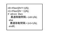
本発明を実施するためには、受信素子の配列数Nと、分割数パラメータkから、図5や図7に示した最適移動間隔(n±1/k)を具体的に計算できることが重要である。最適移動間隔(n±1/k)は例えば、図11に示したような手順により計算することができる。図11において、関数Floor[x]は、xを超えない最大整数を求める関数である。
Example 3
FIG. 7 specifically shows the division number k, the optimum moving interval, and the moving distance per light emitting cycle when the element number N = 13. If the division number k is large, the moving distance per light emitting cycle decreases, but while continuously moving at a constant speed, it is possible to acquire a photoacoustic signal with k times the density.
In order to carry out the present invention, it is important to be able to specifically calculate the optimum moving interval (n ± 1 / k) shown in FIG. 5 and FIG. 7 from the number N of receiving elements and the division number parameter k. is there. The optimal movement interval (n ± 1 / k) can be calculated, for example, by the procedure as shown in FIG. In FIG. 11, the function Floor [x] is a function for obtaining the largest integer not exceeding x.
レーザ発光周期をΔT、プローブの素子配列間隔をdとすると、本発明に関わるプローブの移動速度Vは、以下の式(1)で表すことができる。
V=(最適移動間隔)×d/(ΔT) …(1)
従って、配列素子数Nのプローブ8を用いてk倍の密度の光超音波信号を入力するためには、移動台の移動速度を式(1)の速度Vに設定すれば良いことが分かる。
逆に、分割数kとレーザ発光ごとの移動間隔(n±1/k)とから必要な配列素子数Nを計算することもできる。素子数Nの具体的な計算式は、式(2)で表される。
N=k×(n±1/k) …(2)
従って、希望移動速度Vと分割数kとから式(1)に基づいて移動間隔を計算すれば、その移動間隔を元に式(2)から最小限必要な受信素子配列数Nを容易に求められる。すなわち、式(2)で計算されたN以上の受信素子を配列したプローブであれば、希望移動速度Vと分割数kを実現するように光音響信号を取得可能である。
Assuming that the laser emission period is ΔT and the element arrangement interval of the probe is d, the moving velocity V of the probe according to the present invention can be expressed by the following equation (1).
V = (optimum movement interval) × d / (ΔT) (1)
Therefore, it can be understood that the moving speed of the moving table may be set to the speed V of the equation (1) in order to input the optical ultrasonic signal of density k times that of the array element number N using the
Conversely, the required number N of array elements can also be calculated from the division number k and the movement interval (n ± 1 / k) for each laser emission. A specific calculation formula of the number N of elements is expressed by Formula (2).
N = k × (n ± 1 / k) (2)
Therefore, if the movement interval is calculated from the desired movement speed V and the division number k based on the equation (1), the minimum required receiving element array number N can be easily obtained from the equation (2) based on the movement interval. Be That is, in the case of a probe in which N or more receiving elements calculated by equation (2) are arrayed, the photoacoustic signal can be acquired so as to realize the desired moving speed V and the division number k.
このことは、次のように言い換えることができる。有効入力範囲を設定するには、プローブの移動距離に応じて、第1の方向において所定以上の数の受信素子が必要となる。プローブが配列間隔dの(n+1/k)倍の距離を移動するごとに光源から光が照射されるような制御がなされる場合、少なくとも(n×k+1)個の素子が必要である。また、プローブが配列間隔dの(n−1/k)倍の距離を移動するごとに光源から光が照射されるような制御がなされる場合、少なくとも(n×k−1)個の受信素子が必要である。これにより、細かい間隔での光音響信号を抜けがないように取得できる。 This can be reworded as follows. In order to set the effective input range, a predetermined number or more of receiving elements are required in the first direction according to the movement distance of the probe. When control is performed such that light is emitted from the light source each time the probe moves a distance (n + 1 / k) times the arrangement interval d, at least (n × k + 1) elements are required. In addition, when control is performed such that light is emitted from the light source every time the probe moves a distance (n-1 / k) times the arrangement interval d, at least (n × k-1) reception elements is necessary. Thereby, the photoacoustic signals at fine intervals can be acquired without omission.
<実施例4>
図8は、受信素子数N=10とした場合の信号取得を示す。これは、図3のプローブの2倍の素子数である。このようにすれば、図の有効入力範囲内では、被検体上の同じ位置で発生した光音響波に由来する光音響信号が二つずつ入力されるので、加算平均によりSN比を向上させられる。同様に受信素子の数をM倍にすれば、同じ位置でM個の信号取得が可能となるので、SN比のさらなる向上が可能となる。
Example 4
FIG. 8 shows signal acquisition when the number of receiving elements is N = 10. This is twice as many elements as the probe of FIG. In this way, the photoacoustic signal derived from the photoacoustic wave generated at the same position on the subject is input two by two within the effective input range of the figure, so that the SN ratio can be improved by averaging. . Similarly, if the number of receiving elements is multiplied by M, M signals can be acquired at the same position, and thus the SN ratio can be further improved.
<実施例5>
以上の説明では、プローブを、受信素子の配列方向に直線的に機械走査していた。図9は、プローブを円周に沿って機械走査する場合を示す。図9(a)は、円筒状の被検体901の外側に沿って走査する様子を示す。この場合、円筒状被検体を輪切りにするような断層像が生成できる。図9(b)は、被検体902の表面を円形に走査する様子を示す。この場合、紙面の奥行き方向に向かって円筒状の断層像が生成できる。
Example 5
In the above description, the probe is mechanically scanned linearly in the arrangement direction of the receiving elements. FIG. 9 shows the case of mechanically scanning the probe along the circumference. FIG. 9A shows a state of scanning along the outside of a
<変形例>
以上の実施例では、説明を簡単にするため、受信素子を第1の方向に配列した1次元プローブを示した。しかし本発明は、受信素子を2次元的に配列した2次元プローブにも適用できる。この場合、第1の方向に交差する第2の方向(典型的には直交)にも素子が配列される。2次元プローブは、1次元プローブが複数個並列に動作していると考えられる。かかる2次元プローブを用いることで、被検体上の広い領域を高速に走査できる。
更に、2次元プローブを、第2の配列方向に対しても第1の方向と同様に、受信素子配列間隔の(n±1/k)倍ずつ移動させるようにしても良い。このような制御により、第2の方向においても、受信素子配列間隔の1/kの間隔で光音響信号を取得できるようになる。
また、スパース型プローブのように、素子が隣接せず間隔がある場合でも、素子間隔をdとして本発明を適用することに支障はない。
また、光源としては、上述のパルスレーザ装置に限らず、マイクロ波やLED光などを含む電磁波の発生装置を用いてもよい。
<Modification>
In the above embodiments, in order to simplify the description, the one-dimensional probe in which the receiving elements are arranged in the first direction is shown. However, the present invention can also be applied to a two-dimensional probe in which receiving elements are two-dimensionally arranged. In this case, the elements are also arranged in a second direction (typically orthogonal) crossing the first direction. The two-dimensional probe is considered to have a plurality of one-dimensional probes operating in parallel. By using such a two-dimensional probe, a large area on the subject can be scanned at high speed.
Furthermore, the two-dimensional probe may be moved in the second arrangement direction by (n ± 1 / k) times the receiving element arrangement interval as in the first direction. Such control makes it possible to acquire photoacoustic signals at an interval of 1 / k of the receiving element arrangement interval also in the second direction.
Furthermore, even when there are elements adjacent to each other without spacing, as in the case of a sparse probe, there is no problem in applying the present invention to the element spacing d.
Moreover, as a light source, you may use not only the above-mentioned pulse laser apparatus but the generator of electromagnetic waves containing a microwave, LED light, etc. in it.
<実施例6>
上記各実施例では、プローブは光音響波を受信するものとして構成されていた。しかし、被検体に送信されたのち被検体内で反射した超音波(エコー波)を音源とすることもできる。超音波音源の場合であっても、超音波音源が被検体に固定されていれば、プローブの移動にかかわらず検出対象6からは常に同一のエコー波が発生するので、光音響波の場合と同様に本発明を適用することができる。この場合の超音波音源は単一であっても良いし、同期して動作する複数の音源から構成されていても良い。
また、超音波音源は、プローブの移動方向に平行な平面波を発生するものであれば、移動するプローブに固定されていても良い。この場合でも、プローブの移動にかかわらず、同一地点の受信素子が受信する音響波はほぼ同一となるので、本発明を適用できる。
Example 6
In each of the above embodiments, the probe is configured to receive the photoacoustic wave. However, an ultrasonic wave (echo wave) reflected in the subject after being transmitted to the subject may be used as a sound source. Even in the case of the ultrasonic sound source, if the ultrasonic sound source is fixed to the subject, the same echo wave is always generated from the
The ultrasonic source may be fixed to a moving probe as long as it generates a plane wave parallel to the moving direction of the probe. Even in this case, the present invention can be applied because the acoustic waves received by the receiving elements at the same point are almost the same regardless of the movement of the probe.
図10は、本実施例の超音波イメージング装置の構成を示す。図中、符号201は、被検体に対して固定した位置から超音波パルスを発生する超音波送信器である。符号202は、超音波送信器201を駆動する超音波信号発生回路であり、超音波パルスを超音波送信器01から被検体に照射させる。
このように、超音波送信器201が被検体位置に対して固定した位置であれば、被検体1の内部の検出対象6からは常時同じエコー波が発生するので、本発明を適用でき、上述した効果が得られる。
FIG. 10 shows the configuration of the ultrasound imaging apparatus of this embodiment. In the figure,
As described above, if the
3a、3b:移動台,4:パルスレーザ光源,5:照射光,7:光音響波,8:プローブ,9:受信電気信号,11:計算機,13:レーザ光源制御回路,14:移動台制御回路,15:AD変換回路,16:記憶回路,17:画像再構成回路 3a, 3b: moving table, 4: pulse laser light source, 5: irradiation light, 7: photoacoustic wave, 8: probe, 9: reception electric signal, 11: computer, 13: laser light source control circuit, 14: moving table control Circuit, 15: AD converter circuit, 16: memory circuit, 17: image reconstruction circuit
Claims (19)
前記光源からの光を照射された被検体から発生する音響波を受信して電気信号に変換する複数の受信素子が第1の方向に配列されたプローブと、
前記プローブを前記第1の方向に移動させる移動手段と、
前記光源および前記移動手段を制御する制御手段と、
を有し、
nを1以上の整数、kを2以上の整数、dを前記受信素子の配列間隔としたとき、前記制御手段は、前記プローブを前記第1の方向に、(n+1/k)×d/ΔTまたは(n−1/k)×d/ΔTで表現される速度で連続移動させながら、前記プローブが前記受信素子の配列間隔dの(n+1/k)倍または(n−1/k)倍の距離を移動するごとに、前記光源から光が照射されるように制御を行う
ことを特徴とする被検体情報取得装置。 A light source emitting light with a repetition period ΔT;
A probe in which a plurality of receiving elements for receiving an acoustic wave generated from a subject irradiated with light from the light source and converting it into an electric signal are arranged in a first direction;
Moving means for moving the probe in the first direction;
Control means for controlling the light source and the moving means;
Have
When n is an integer of 1 or more, k is an integer of 2 or more, and d is an arrangement interval of the receiving elements, the control means sets (n + 1 / k) × d / ΔT in the first direction. Alternatively, while continuously moving at a speed represented by (n-1 / k) × d / ΔT, the probe is (n + 1 / k) or (n-1 / k) times the arrangement interval d of the receiving elements An object information acquiring apparatus characterized in that control is performed so that light is emitted from the light source each time the distance is moved.
ことを特徴とする請求項1に記載の被検体情報取得装置。 The object information acquiring apparatus according to claim 1, wherein the moving unit moves the probe at a constant speed.
前記制御手段は、前記プローブが前記受信素子の配列間隔の(n+1/k)倍の距離を移動するごとに前記光源から光が照射されるような制御を行う
ことを特徴とする請求項1または2に記載の被検体情報取得装置。 The probe has at least (n × k + 1) receiving elements arranged in the first direction,
The control means performs control such that light is emitted from the light source each time the probe moves a distance (n + 1 / k) times the arrangement interval of the receiving elements. The object information acquisition apparatus according to 2.
前記制御手段は、前記プローブが前記受信素子の配列間隔の(n−1/k)倍の距離を移動するごとに前記光源から光が照射されるような制御を行う
ことを特徴とする請求項1または2に記載の被検体情報取得装置。 The probe has at least (n × k−1) receiving elements arranged in the first direction,
The control means performs control such that light is emitted from the light source each time the probe moves a distance (n-1 / k) times the arrangement interval of the receiving elements. The object information acquisition apparatus according to 1 or 2.
ことを特徴とする請求項1ないし4のいずれか1項に記載の被検体情報取得装置。 The object information acquiring apparatus according to any one of claims 1 to 4, wherein the probe has a receiving element arranged in a second direction crossing the first direction. .
前記AD変換手段で変換された前記デジタル信号を記憶する記憶手段と、
前記記憶手段に記憶された前記デジタル信号に基づいて前記被検体内部の画像データを生成する生成手段と、
をさらに有することを特徴とする請求項1ないし5のいずれか1項に記載の被検体情報取得装置。 AD conversion means for converting the electrical signal converted by the receiving element into a digital signal;
Storage means for storing the digital signal converted by the AD conversion means;
Generation means for generating image data inside the subject based on the digital signal stored in the storage means;
The subject information acquiring apparatus according to any one of claims 1 to 5, further comprising:
ことを特徴とする請求項6に記載の被検体情報取得装置。 The generation means adds and averages the digital signals derived from the acoustic wave received at the same position on the subject, and generates image data inside the subject based on the added and averaged signal. The object information acquisition apparatus according to claim 6, characterized in that
ことを特徴とする請求項1ないし7のいずれか1項に記載の被検体情報取得装置。 The object information acquiring apparatus according to any one of claims 1 to 7, wherein the control means moves the light source and the probe in synchronization with each other.
をさらに有することを特徴とする請求項6に記載の被検体情報取得装置。 7. The object information acquiring apparatus according to claim 6, further comprising display means for displaying an image based on the image data generated by the generation means.
Floor関数が下式を満たす場合には、n=Floor[(N+1)/k]、として、前記プローブが前記受信素子の配列間隔の(n−1/k)倍の距離を移動するごとに、前記光源から光が照射されるように制御を行い、
前記Floor関数が下式を満たさない場合には、n=Floor[(N−1)/k]、として、前記プローブが前記受信素子の配列間隔の(n+1/k)倍の距離を移動するごとに、前記光源から光が照射されるように制御を行う
ことを特徴とする請求項1ないし9のいずれか1項に記載の被検体情報取得装置。
Floor[(N+1)/k]>Floor[(N−1)/k] …(式) When the control means sets the number of the plurality of receiving elements to N,
If the Floor function satisfies the following formula, then n = Floor [(N + 1) / k], each time the probe moves a distance (n-1 / k) times the array spacing of the receiving elements, Control so that light is emitted from the light source,
When the Floor function does not satisfy the following equation, each time the probe moves a distance (n + 1 / k) times the arrangement interval of the receiving elements, as n = Floor [(N-1) / k]. The subject information acquiring apparatus according to any one of claims 1 to 9, wherein control is performed so that light is emitted from the light source.
Floor [(N + 1) / k]> Floor [(N-1) / k] (Expression)
を有する被検体情報取得装置の制御方法であって、
前記複数の受信素子が、前記光源からの光を照射された被検体から発生する音響波を受信して電気信号に変換する受信ステップを有し、
nを1以上の整数、kを2以上の整数、dを前記受信素子の配列間隔としたとき、前記受信ステップにおいて、前記プローブを前記第1の方向に、(n+1/k)×d/ΔTまたは(n−1/k)×d/ΔTで表現される速度で連続移動させながら、前記プローブが前記受信素子の配列間隔dの(n+1/k)倍または(n−1/k)倍の距離を移動するごとに、前記光源から光が照射されるように制御を行う
ことを特徴とする被検体情報取得装置の制御方法。 A light source emitting light with a repetition period ΔT, a probe in which a plurality of receiving elements are arranged in a first direction, and moving means for moving the probe in the first direction;
A control method of a subject information acquisition apparatus having
The plurality of receiving elements have a receiving step of receiving light from the light source and receiving an acoustic wave generated from the object and converting the light into an electrical signal.
In the receiving step, when n is an integer of 1 or more, k is an integer of 2 or more, and d is an arrangement interval of the receiving elements, in the receiving step, the probe is (n + 1 / k) × d / ΔT in the first direction. Alternatively, while continuously moving at a speed represented by (n-1 / k) × d / ΔT, the probe is (n + 1 / k) or (n-1 / k) times the arrangement interval d of the receiving elements A control method of an object information acquiring apparatus, wherein control is performed so that light is emitted from the light source each time the distance is moved.
ことを特徴とする請求項11に記載の被検体情報取得装置の制御方法。 The control method of the object information acquiring apparatus according to claim 11 , wherein the moving means moves the probe at a constant speed.
前記プローブが前記受信素子の配列間隔の(n+1/k)倍の距離を移動するごとに前
記光源から光が照射されるような制御を行う
ことを特徴とする請求項11または12に記載の被検体情報取得装置の制御方法。 The probe has at least (n × k + 1) receiving elements arranged in the first direction,
The control according to claim 11 or 12 , wherein control is performed such that light is emitted from the light source each time the probe moves a distance (n + 1 / k) times the arrangement interval of the receiving elements. Control method of sample information acquisition apparatus.
前記プローブが前記受信素子の配列間隔の(n−1/k)倍の距離を移動するごとに前記光源から光が照射されるような制御を行う
ことを特徴とする請求項11または12に記載の被検体情報取得装置の制御方法。 The probe has at least (n × k−1) receiving elements arranged in the first direction,
According to claim 11 or 12, characterized in the light from the light source be controlled as irradiated each time the probe is moved (n-1 / k) times the distance of the array pitch of the receiving element Method of controlling an object information acquisition apparatus
ことを特徴とする請求項11ないし14のいずれか1項に記載の被検体情報取得装置の制御方法。 The object information acquiring apparatus according to any one of claims 11 to 14 , wherein the probe has a receiving element arranged in a second direction intersecting with the first direction. Control method.
前記デジタル信号を記憶手段に記憶する記憶ステップと、
前記記憶手段に記憶された前記デジタル信号に基づいて前記被検体内部の画像データを生成する生成ステップと、
をさらに有することを特徴とする請求項11ないし15のいずれか1項に記載の被検体情報取得装置の制御方法。 Converting the electrical signal converted by the receiving element into a digital signal;
Storing the digital signal in storage means;
Generating image data of the inside of the subject based on the digital signal stored in the storage means;
The control method of the object information acquiring apparatus according to any one of claims 11 to 15 , further comprising:
ことを特徴とする請求項16に記載の被検体情報取得装置の制御方法。 The digital signals derived from the acoustic wave received at the same position on the subject are added and averaged, and image data of the inside of the subject is generated based on the added signal. The control method of the object information acquisition apparatus according to Item 16 .
ことを特徴とする請求項11ないし17のいずれか1項に記載の被検体情報取得装置の制御方法。 The control method of the object information acquiring apparatus according to any one of claims 11 to 17 , wherein the light source and the probe are moved in synchronization with each other.
Priority Applications (2)
| Application Number | Priority Date | Filing Date | Title |
|---|---|---|---|
| JP2013073462A JP6508867B2 (en) | 2013-03-29 | 2013-03-29 | Object information acquisition apparatus and control method therefor |
| US14/207,881 US9924876B2 (en) | 2013-03-29 | 2014-03-13 | Object information acquiring apparatus and method of controlling same |
Applications Claiming Priority (1)
| Application Number | Priority Date | Filing Date | Title |
|---|---|---|---|
| JP2013073462A JP6508867B2 (en) | 2013-03-29 | 2013-03-29 | Object information acquisition apparatus and control method therefor |
Related Child Applications (1)
| Application Number | Title | Priority Date | Filing Date |
|---|---|---|---|
| JP2018012602A Division JP2018061901A (en) | 2018-01-29 | 2018-01-29 | Subject information acquisition device and control method thereof |
Publications (3)
| Publication Number | Publication Date |
|---|---|
| JP2014195615A JP2014195615A (en) | 2014-10-16 |
| JP2014195615A5 JP2014195615A5 (en) | 2016-04-28 |
| JP6508867B2 true JP6508867B2 (en) | 2019-05-08 |
Family
ID=51621513
Family Applications (1)
| Application Number | Title | Priority Date | Filing Date |
|---|---|---|---|
| JP2013073462A Expired - Fee Related JP6508867B2 (en) | 2013-03-29 | 2013-03-29 | Object information acquisition apparatus and control method therefor |
Country Status (2)
| Country | Link |
|---|---|
| US (1) | US9924876B2 (en) |
| JP (1) | JP6508867B2 (en) |
Families Citing this family (1)
| Publication number | Priority date | Publication date | Assignee | Title |
|---|---|---|---|---|
| JP6399911B2 (en) * | 2014-11-28 | 2018-10-03 | キヤノン株式会社 | Subject information acquisition device |
Family Cites Families (18)
| Publication number | Priority date | Publication date | Assignee | Title |
|---|---|---|---|---|
| AU4751597A (en) | 1996-10-04 | 1998-04-24 | Ilex Oncology, Inc. | Dfmo and taxol for the treatment or prevention of breast cancer |
| US5713356A (en) | 1996-10-04 | 1998-02-03 | Optosonics, Inc. | Photoacoustic breast scanner |
| JP4406226B2 (en) | 2003-07-02 | 2010-01-27 | 株式会社東芝 | Biological information video device |
| JP2008264218A (en) * | 2007-04-20 | 2008-11-06 | Toshiba Corp | Ultrasonic probe |
| JP4448189B2 (en) * | 2008-06-18 | 2010-04-07 | キヤノン株式会社 | Biological information acquisition device |
| JP5393256B2 (en) | 2009-05-25 | 2014-01-22 | キヤノン株式会社 | Ultrasonic device |
| JP5448785B2 (en) * | 2009-12-18 | 2014-03-19 | キヤノン株式会社 | Measuring device, movement control method, and program |
| JP5645421B2 (en) | 2010-02-23 | 2014-12-24 | キヤノン株式会社 | Ultrasonic imaging apparatus and delay control method |
| JP5448918B2 (en) * | 2010-02-24 | 2014-03-19 | キヤノン株式会社 | Biological information processing device |
| JP5637725B2 (en) | 2010-04-12 | 2014-12-10 | キヤノン株式会社 | Acoustic wave imaging device |
| JP5721462B2 (en) | 2011-02-09 | 2015-05-20 | キヤノン株式会社 | Subject information acquisition device |
| JP5864894B2 (en) | 2011-05-10 | 2016-02-17 | キヤノン株式会社 | Subject information acquisition apparatus and signal processing apparatus |
| JP2012235832A (en) | 2011-05-10 | 2012-12-06 | Canon Inc | Object information acquiring apparatus |
| WO2013046437A1 (en) * | 2011-09-30 | 2013-04-04 | キヤノン株式会社 | Test object information-acquiring apparatus |
| JP5950540B2 (en) | 2011-10-31 | 2016-07-13 | キヤノン株式会社 | SUBJECT INFORMATION ACQUISITION DEVICE, CONTROL METHOD FOR THE DEVICE, AND PROGRAM |
| JP5836760B2 (en) | 2011-11-04 | 2015-12-24 | キヤノン株式会社 | Acoustic wave acquisition apparatus and acoustic wave acquisition method |
| JP5936330B2 (en) | 2011-11-04 | 2016-06-22 | キヤノン株式会社 | Acoustic wave measuring device and control method of acoustic wave measuring device |
| JP2013094539A (en) | 2011-11-04 | 2013-05-20 | Canon Inc | Subject-information acquisition device and control method for the same |
-
2013
- 2013-03-29 JP JP2013073462A patent/JP6508867B2/en not_active Expired - Fee Related
-
2014
- 2014-03-13 US US14/207,881 patent/US9924876B2/en active Active
Also Published As
| Publication number | Publication date |
|---|---|
| US9924876B2 (en) | 2018-03-27 |
| JP2014195615A (en) | 2014-10-16 |
| US20140296689A1 (en) | 2014-10-02 |
Similar Documents
| Publication | Publication Date | Title |
|---|---|---|
| JP5275830B2 (en) | Optical ultrasonic tomographic imaging apparatus and optical ultrasonic tomographic imaging method | |
| EP2512328B1 (en) | Photoacoustic measurement apparatus, movement control method, and program | |
| US20110098550A1 (en) | Photoacoustic imaging apparatus | |
| US20090198128A1 (en) | Biological information imaging apparatus and method for analyzing biological information | |
| JP2013042996A (en) | Test object information acquisition device | |
| JP5681141B2 (en) | Tomographic image generating apparatus, method, and program | |
| JP6525565B2 (en) | Object information acquisition apparatus and object information acquisition method | |
| JP2014054517A (en) | Device and method for generating photoacoustic image | |
| JP2013056032A (en) | Object information acquiring apparatus and object information acquiring method | |
| JP2015216982A (en) | Photo-acoustic apparatus | |
| JP6656229B2 (en) | Photoacoustic device | |
| JP2012239714A (en) | Biological object information acquisition apparatus | |
| JP6475369B2 (en) | Acoustic wave image generation apparatus and acoustic wave image generation method | |
| JP6508867B2 (en) | Object information acquisition apparatus and control method therefor | |
| US20150320321A1 (en) | Object information acquiring apparatus | |
| JP6091235B2 (en) | Subject information acquisition device | |
| JP5683232B2 (en) | Subject information acquisition device | |
| JP2018061901A (en) | Subject information acquisition device and control method thereof | |
| US20160206246A1 (en) | Object information acquiring apparatus and object information acquisition method | |
| EP3025642A1 (en) | Subject information acquiring apparatus | |
| JP6636092B2 (en) | Subject information acquisition device | |
| KR102146958B1 (en) | Photoacoustic scan imaging apparatus | |
| JP6362122B2 (en) | Subject information acquisition apparatus and subject information acquisition method | |
| JP6563097B2 (en) | Subject information acquisition device | |
| JP2016027926A (en) | Subject information acquisition device |
Legal Events
| Date | Code | Title | Description |
|---|---|---|---|
| A521 | Request for written amendment filed |
Free format text: JAPANESE INTERMEDIATE CODE: A523 Effective date: 20160314 |
|
| A621 | Written request for application examination |
Free format text: JAPANESE INTERMEDIATE CODE: A621 Effective date: 20160314 |
|
| A977 | Report on retrieval |
Free format text: JAPANESE INTERMEDIATE CODE: A971007 Effective date: 20170131 |
|
| A131 | Notification of reasons for refusal |
Free format text: JAPANESE INTERMEDIATE CODE: A131 Effective date: 20170228 |
|
| A521 | Request for written amendment filed |
Free format text: JAPANESE INTERMEDIATE CODE: A523 Effective date: 20170501 |
|
| A02 | Decision of refusal |
Free format text: JAPANESE INTERMEDIATE CODE: A02 Effective date: 20171031 |
|
| A521 | Request for written amendment filed |
Free format text: JAPANESE INTERMEDIATE CODE: A523 Effective date: 20180129 |
|
| A911 | Transfer to examiner for re-examination before appeal (zenchi) |
Free format text: JAPANESE INTERMEDIATE CODE: A911 Effective date: 20180206 |
|
| A912 | Re-examination (zenchi) completed and case transferred to appeal board |
Free format text: JAPANESE INTERMEDIATE CODE: A912 Effective date: 20180302 |
|
| RD02 | Notification of acceptance of power of attorney |
Free format text: JAPANESE INTERMEDIATE CODE: A7422 Effective date: 20181116 |
|
| A521 | Request for written amendment filed |
Free format text: JAPANESE INTERMEDIATE CODE: A523 Effective date: 20181211 |
|
| A61 | First payment of annual fees (during grant procedure) |
Free format text: JAPANESE INTERMEDIATE CODE: A61 Effective date: 20190402 |
|
| R151 | Written notification of patent or utility model registration |
Ref document number: 6508867 Country of ref document: JP Free format text: JAPANESE INTERMEDIATE CODE: R151 |
|
| LAPS | Cancellation because of no payment of annual fees |