EP2435809B1 - Machine et procédé de surveillance de l'état d'un palier de secours d'une machine - Google Patents
Machine et procédé de surveillance de l'état d'un palier de secours d'une machine Download PDFInfo
- Publication number
- EP2435809B1 EP2435809B1 EP10718521.7A EP10718521A EP2435809B1 EP 2435809 B1 EP2435809 B1 EP 2435809B1 EP 10718521 A EP10718521 A EP 10718521A EP 2435809 B1 EP2435809 B1 EP 2435809B1
- Authority
- EP
- European Patent Office
- Prior art keywords
- machine
- outer ring
- bearing
- sensor
- safety bearing
- Prior art date
- Legal status (The legal status is an assumption and is not a legal conclusion. Google has not performed a legal analysis and makes no representation as to the accuracy of the status listed.)
- Active
Links
- 238000000034 method Methods 0.000 title claims description 25
- 238000012544 monitoring process Methods 0.000 title claims description 9
- 230000033001 locomotion Effects 0.000 claims description 13
- 238000011144 upstream manufacturing Methods 0.000 claims 2
- 230000010355 oscillation Effects 0.000 claims 1
- 238000012423 maintenance Methods 0.000 description 7
- 238000011156 evaluation Methods 0.000 description 4
- 230000001276 controlling effect Effects 0.000 description 3
- 238000006073 displacement reaction Methods 0.000 description 3
- 238000005096 rolling process Methods 0.000 description 3
- 238000012549 training Methods 0.000 description 3
- 230000005540 biological transmission Effects 0.000 description 2
- 230000002950 deficient Effects 0.000 description 2
- 238000001514 detection method Methods 0.000 description 2
- 238000005259 measurement Methods 0.000 description 2
- 239000000725 suspension Substances 0.000 description 2
- 230000002123 temporal effect Effects 0.000 description 2
- 238000010276 construction Methods 0.000 description 1
- 230000001419 dependent effect Effects 0.000 description 1
- 238000013461 design Methods 0.000 description 1
- 230000002542 deteriorative effect Effects 0.000 description 1
- 238000010586 diagram Methods 0.000 description 1
- 230000000694 effects Effects 0.000 description 1
- 235000013490 limbo Nutrition 0.000 description 1
- 239000007788 liquid Substances 0.000 description 1
- 230000001105 regulatory effect Effects 0.000 description 1
- 230000035939 shock Effects 0.000 description 1
Images


Classifications
-
- H—ELECTRICITY
- H02—GENERATION; CONVERSION OR DISTRIBUTION OF ELECTRIC POWER
- H02K—DYNAMO-ELECTRIC MACHINES
- H02K7/00—Arrangements for handling mechanical energy structurally associated with dynamo-electric machines, e.g. structural association with mechanical driving motors or auxiliary dynamo-electric machines
- H02K7/08—Structural association with bearings
- H02K7/09—Structural association with bearings with magnetic bearings
-
- F—MECHANICAL ENGINEERING; LIGHTING; HEATING; WEAPONS; BLASTING
- F16—ENGINEERING ELEMENTS AND UNITS; GENERAL MEASURES FOR PRODUCING AND MAINTAINING EFFECTIVE FUNCTIONING OF MACHINES OR INSTALLATIONS; THERMAL INSULATION IN GENERAL
- F16C—SHAFTS; FLEXIBLE SHAFTS; ELEMENTS OR CRANKSHAFT MECHANISMS; ROTARY BODIES OTHER THAN GEARING ELEMENTS; BEARINGS
- F16C19/00—Bearings with rolling contact, for exclusively rotary movement
- F16C19/02—Bearings with rolling contact, for exclusively rotary movement with bearing balls essentially of the same size in one or more circular rows
- F16C19/14—Bearings with rolling contact, for exclusively rotary movement with bearing balls essentially of the same size in one or more circular rows for both radial and axial load
- F16C19/18—Bearings with rolling contact, for exclusively rotary movement with bearing balls essentially of the same size in one or more circular rows for both radial and axial load with two or more rows of balls
-
- F—MECHANICAL ENGINEERING; LIGHTING; HEATING; WEAPONS; BLASTING
- F16—ENGINEERING ELEMENTS AND UNITS; GENERAL MEASURES FOR PRODUCING AND MAINTAINING EFFECTIVE FUNCTIONING OF MACHINES OR INSTALLATIONS; THERMAL INSULATION IN GENERAL
- F16C—SHAFTS; FLEXIBLE SHAFTS; ELEMENTS OR CRANKSHAFT MECHANISMS; ROTARY BODIES OTHER THAN GEARING ELEMENTS; BEARINGS
- F16C19/00—Bearings with rolling contact, for exclusively rotary movement
- F16C19/52—Bearings with rolling contact, for exclusively rotary movement with devices affected by abnormal or undesired conditions
- F16C19/522—Bearings with rolling contact, for exclusively rotary movement with devices affected by abnormal or undesired conditions related to load on the bearing, e.g. bearings with load sensors or means to protect the bearing against overload
-
- F—MECHANICAL ENGINEERING; LIGHTING; HEATING; WEAPONS; BLASTING
- F16—ENGINEERING ELEMENTS AND UNITS; GENERAL MEASURES FOR PRODUCING AND MAINTAINING EFFECTIVE FUNCTIONING OF MACHINES OR INSTALLATIONS; THERMAL INSULATION IN GENERAL
- F16C—SHAFTS; FLEXIBLE SHAFTS; ELEMENTS OR CRANKSHAFT MECHANISMS; ROTARY BODIES OTHER THAN GEARING ELEMENTS; BEARINGS
- F16C19/00—Bearings with rolling contact, for exclusively rotary movement
- F16C19/52—Bearings with rolling contact, for exclusively rotary movement with devices affected by abnormal or undesired conditions
- F16C19/525—Bearings with rolling contact, for exclusively rotary movement with devices affected by abnormal or undesired conditions related to temperature and heat, e.g. insulation
-
- F—MECHANICAL ENGINEERING; LIGHTING; HEATING; WEAPONS; BLASTING
- F16—ENGINEERING ELEMENTS AND UNITS; GENERAL MEASURES FOR PRODUCING AND MAINTAINING EFFECTIVE FUNCTIONING OF MACHINES OR INSTALLATIONS; THERMAL INSULATION IN GENERAL
- F16C—SHAFTS; FLEXIBLE SHAFTS; ELEMENTS OR CRANKSHAFT MECHANISMS; ROTARY BODIES OTHER THAN GEARING ELEMENTS; BEARINGS
- F16C32/00—Bearings not otherwise provided for
- F16C32/04—Bearings not otherwise provided for using magnetic or electric supporting means
- F16C32/0406—Magnetic bearings
- F16C32/044—Active magnetic bearings
- F16C32/0442—Active magnetic bearings with devices affected by abnormal, undesired or non-standard conditions such as shock-load, power outage, start-up or touchdown
-
- F—MECHANICAL ENGINEERING; LIGHTING; HEATING; WEAPONS; BLASTING
- F16—ENGINEERING ELEMENTS AND UNITS; GENERAL MEASURES FOR PRODUCING AND MAINTAINING EFFECTIVE FUNCTIONING OF MACHINES OR INSTALLATIONS; THERMAL INSULATION IN GENERAL
- F16C—SHAFTS; FLEXIBLE SHAFTS; ELEMENTS OR CRANKSHAFT MECHANISMS; ROTARY BODIES OTHER THAN GEARING ELEMENTS; BEARINGS
- F16C32/00—Bearings not otherwise provided for
- F16C32/04—Bearings not otherwise provided for using magnetic or electric supporting means
- F16C32/0406—Magnetic bearings
- F16C32/044—Active magnetic bearings
- F16C32/0444—Details of devices to control the actuation of the electromagnets
-
- F—MECHANICAL ENGINEERING; LIGHTING; HEATING; WEAPONS; BLASTING
- F16—ENGINEERING ELEMENTS AND UNITS; GENERAL MEASURES FOR PRODUCING AND MAINTAINING EFFECTIVE FUNCTIONING OF MACHINES OR INSTALLATIONS; THERMAL INSULATION IN GENERAL
- F16C—SHAFTS; FLEXIBLE SHAFTS; ELEMENTS OR CRANKSHAFT MECHANISMS; ROTARY BODIES OTHER THAN GEARING ELEMENTS; BEARINGS
- F16C32/00—Bearings not otherwise provided for
- F16C32/04—Bearings not otherwise provided for using magnetic or electric supporting means
- F16C32/0406—Magnetic bearings
- F16C32/044—Active magnetic bearings
- F16C32/0474—Active magnetic bearings for rotary movement
- F16C32/048—Active magnetic bearings for rotary movement with active support of two degrees of freedom, e.g. radial magnetic bearings
-
- F—MECHANICAL ENGINEERING; LIGHTING; HEATING; WEAPONS; BLASTING
- F16—ENGINEERING ELEMENTS AND UNITS; GENERAL MEASURES FOR PRODUCING AND MAINTAINING EFFECTIVE FUNCTIONING OF MACHINES OR INSTALLATIONS; THERMAL INSULATION IN GENERAL
- F16C—SHAFTS; FLEXIBLE SHAFTS; ELEMENTS OR CRANKSHAFT MECHANISMS; ROTARY BODIES OTHER THAN GEARING ELEMENTS; BEARINGS
- F16C39/00—Relieving load on bearings
- F16C39/02—Relieving load on bearings using mechanical means
-
- F—MECHANICAL ENGINEERING; LIGHTING; HEATING; WEAPONS; BLASTING
- F16—ENGINEERING ELEMENTS AND UNITS; GENERAL MEASURES FOR PRODUCING AND MAINTAINING EFFECTIVE FUNCTIONING OF MACHINES OR INSTALLATIONS; THERMAL INSULATION IN GENERAL
- F16C—SHAFTS; FLEXIBLE SHAFTS; ELEMENTS OR CRANKSHAFT MECHANISMS; ROTARY BODIES OTHER THAN GEARING ELEMENTS; BEARINGS
- F16C41/00—Other accessories, e.g. devices integrated in the bearing not relating to the bearing function as such
- F16C41/007—Encoders, e.g. parts with a plurality of alternating magnetic poles
-
- G—PHYSICS
- G01—MEASURING; TESTING
- G01L—MEASURING FORCE, STRESS, TORQUE, WORK, MECHANICAL POWER, MECHANICAL EFFICIENCY, OR FLUID PRESSURE
- G01L5/00—Apparatus for, or methods of, measuring force, work, mechanical power, or torque, specially adapted for specific purposes
- G01L5/0009—Force sensors associated with a bearing
-
- G—PHYSICS
- G01—MEASURING; TESTING
- G01M—TESTING STATIC OR DYNAMIC BALANCE OF MACHINES OR STRUCTURES; TESTING OF STRUCTURES OR APPARATUS, NOT OTHERWISE PROVIDED FOR
- G01M13/00—Testing of machine parts
- G01M13/04—Bearings
Definitions
- the invention relates to a method for monitoring the condition of a backup bearing of a machine. Furthermore, the invention relates to a related machine.
- magnetic bearings are increasingly used for operational storage of the rotor shaft, which keep the rotating rotor shaft in a limbo state with the aid of magnetic fields.
- the rotor shaft falls into a fishing camp and is caught by this.
- a fishing camp serves to catch the rotor shaft.
- the fishing camp temporarily takes over the bearing of the rotor shaft until complete stop of the rotor shaft.
- catch bearings have to withstand the shock when the rotating rotor shaft crashes into the safety bearing and, on the other hand, ensure a safe coasting of the rotor shaft in the safety bearing.
- the bearing ring of the backup bearing has a slightly larger inner diameter compared to the rotor shaft diameter, so that the rotor shaft in normal operation, i. with active magnetic bearing, the catching bearing does not touch.
- the fishing camp is housed in the region of the respective end of the rotor shaft in the stator housing of the machine.
- the fishing camp When catching the rotor shaft, the fishing camp is exposed to considerable loads, which lead to wear of the backup bearing. Due to the wear, the life of the backup bearing shortens, in the worst case, the fishing camp because of the large wear that can occur in a single outlet of the rotor shaft in the fishing camp, the fishing camp after a single crash of the shaft in the fishing camp, not for another crash is operational.
- the backup bearings are installed in the machine and can usually not be inspected there without dismantling parts of the machine. The optimal moment to replace a defective or deteriorating backup bearing is therefore not sure to determine. So far, the problem has been solved by counting the crashes.
- the backup warehouse When exceeding a predefined number of crashes of the rotor shaft in the fishing camp, eg in five crashes, the backup warehouse must then be replaced. However, the catch camp can already be worn out after less than five crashes or can withstand much more crashes. In the first case, it can lead to the failure of the backup bearing, in the second case to unnecessary and expensive stoppages of the machine to replace not yet defective or worn out bearings.
- a magnetic bearing for supporting a rotor shaft, an auxiliary bearing and a method for catching the rotor shaft upon failure of the magnetic bearing are known.
- the method provides for introducing a liquid into the auxiliary bearing, for example when the temperature of the auxiliary bearing measured by means of a sensor exceeds a predetermined temperature.
- This object is achieved by a method for monitoring the state of a backup bearing of a machine, wherein a rotor shaft of the machine is caught in case of failure of a magnetic bearing of the machine, the backup bearing has an outer ring and a relation to the outer ring rotatably mounted inner ring, wherein For monitoring the condition of the backup bearing, the magnetic bearing is turned off, the rotor shaft is rotatably moved with a defined sequence of movements, the rotor shaft correspondingly driven by the machine, which is controlled by a higher-level control, and by means of a sensor, a physical size of the backup bearing is measured ,
- this object is achieved by a machine, wherein the machine has a magnetic bearing and a backup bearing, wherein the fishing camp a rotor shaft of the machine in case of failure of the magnetic bearing, wherein the fishing camp has an outer ring and a respect to the outer ring rotatably arranged inner ring, wherein for monitoring the state of the backup bearing, the magnetic bearing is switched off, wherein the rotor shaft is rotatably movable with a defined sequence of motions when the magnetic bearing is turned off, the rotor shaft is driven accordingly by the machine, which is controllable by a higher-level control, the machine has a sensor of which a physical Size of the backup bearing is measurable.
- the invention makes it possible to monitor the condition of a backup bearing and to detect whether the backup bearing needs to be replaced because of excessive wear.
- the physical quantity or a variable derived from the physical quantity is compared with a desired size and if the deviation of the physical quantity or the derived size from the desired value exceeds a limit value, a warning message is generated.
- This allows the automatic detection of a worn backup bearing and, e.g. automatically informs an operator of the machine or maintenance personnel if the backup bearing has worn out.
- a safety bearing carrier is arranged, wherein the sensor is arranged on the side of the outer ring facing the safety bearing carrier. At this point, the physical size can be measured very well.
- the physical quantity is present in the form of the temperature of the backup bearing or in the form of a force occurring between the outer ring and the backup bearing carrier or in the form of vibrations of the backup bearing or in the form of a pressure occurring between the outer ring and the backup bearing carrier.
- Temperature, force, pressure or vibrations represent common physical parameters of a backup bearing, which change with increasing wear of the backup bearing.
- the senor is arranged between the outer ring and the safety bearing carrier, since then the force transferred from the safety bearing to the safety bearing carrier can be determined particularly well.
- the senor is formed flat and embedded in a film or disposed on a film, since then the sensor can be installed in a particularly simple manner in the machine.
- a safety bearing carrier is arranged around the outer ring for fastening the safety bearing in the machine, wherein the outer ring has a recess on its side facing the safety bearing carrier in which at least part of the sensor is arranged.
- the sensor can be arranged in a particularly simple manner.
- the physical size is in the form of the distance between the outer ring and inner ring.
- the distance between the outer ring and inner ring represents a common physical size of a backup bearing, which changes with increasing wear of the backup bearing.
- the senor is arranged in the interior of the outer ring. Inside the outer ring, the sensor can be arranged in a particularly simple manner.
- the physical quantity is comparable with a nominal value or with a variable derived from the physical quantity, and if the deviation of the physical quantity or the derived variable from the nominal value exceeds a limit value, a warning message can be generated.
- This allows the automatic detection of a worn backup bearing and, e.g. automatically informs an operator of the machine or maintenance personnel if the backup bearing has worn out.
- the machine may e.g. be designed as an electric motor or generator or compressor or compressor or as a turbine.
- the machine can be designed in particular as a wind power generator.
- FIG. 1 are in the form of a schematic representation, which are essential for the understanding of the invention essential elements of a machine 12, which is formed in the context of the embodiment as an electric motor. Other elements of the machine, such as rotor yoke, etc. are for the sake of clarity and because of the understanding of the invention not essential in FIG. 1 shown.
- the machine 12 has a rotatably arranged, mounted by means of a magnetic bearing 6 rotor shaft 1, which rotates about a rotation axis R during operation of the machine 12.
- a magnetic bearing 6 holds the rotor shaft 1, by means of a controlled magnetic field, in an air gap 21 in suspension.
- the magnetic bearing has for this purpose as essential elements coils for generating the magnetic field.
- the rotor shaft 1 In addition to the magnetic bearing 6, the machine 12 on a fishing camp 14, the rotor shaft 1 catches in case of failure of the magnetic bearing 6 when it falls into the fishing camp 14 and the storage of the rotor shaft 1 takes to standstill of the rotor shaft 1. Such failure of the magnetic bearing 6 may be e.g. occur in case of failure of the power supply of the machine 12 and thus of the magnetic bearing 6.
- the fishing camp 14 has an outer ring 3 and a relation to the outer ring 3 rotatably arranged inner ring 2.
- a safety bearing carrier 4 is arranged, wherein in the embodiment of the safety bearing support 4 is annular and is arranged around the outside of the outer ring 3.
- the fishing camp 14 is inserted into the backup bearing carrier 4.
- the machine 12 has a stationary machine housing 28, to which the backup bearing carrier 4 is attached, wherein the attachment between the backup bearing carrier 4 and the machine housing 28 for clarity in FIG. 1 not shown.
- an air gap 22 is arranged, which is slightly wider than the air gap 21.
- a switched and properly functioning magnetic bearing 6 of the inner ring 2 of the backup bearing 14 has thus no contact with the rotor shaft 1.
- the rotor shaft 1 falls into the fishing camp 14 and there is a mechanical contact between the inner ring 2 and the rotating during operation of the machine 12, in particular fast rotating rotor shaft 1, which often leads to rapid wear of the backup bearing 14.
- the machine 12 has a control device 7, which via electrical lines 8 and electrical lines 9, which in the context of the schematic representation in FIG. 1 are shown as dashes, is connected to the magnetic bearing 6.
- the control device 7 controls the magnetic field generated by the magnetic bearing 6 such that the rotor shaft 1 is held in suspension in the air gap 21 by the magnetic field.
- the control device 7 contains the hiezu necessary control and regulation functions.
- the control device 7 contains power converters for controlling the magnetic bearing 6.
- the measuring devices and feedback branches to the control device 7 necessary for measuring the distance between magnetic bearing 6 and rotor shaft 1 for the control of the magnetic field are for clarity Half and there for the understanding of the invention is immaterial in FIG. 1 not shown.
- the machine 12 has a sensor 5, which measures a physical size G of the backup bearing.
- the measured physical variable G is read in the context of the embodiment of the control device 7.
- the physical size may, for example, in the form of the temperature of the backup bearing or in the form of occurring between the outer ring 3 of the backup bearing 14 and the backup bearing carrier 4 force F or in the form of vibrations of the backup bearing or in the form of an occurring between the outer ring and the backup bearing carrier pressure or in the form the distance between the outer ring and inner ring present.
- the senor can be used, for example, as a temperature sensor for measuring the temperature of the backup bearing or as a force sensor for measuring the force F occurring between the outer ring and the backup bearing carrier or as a vibration sensor for measuring vibrations of the backup bearing or as a pressure sensor for measuring the pressure occurring between the outer ring and the backup bearing carrier or as a displacement sensor for measuring the distance between outer ring and inner ring present.
- the sensor 5 is designed as a force sensor and measures the force F occurring between the outer ring 3 and the safety bearing carrier 4.
- the sensor 5 is arranged between the safety bearing carrier 4 and the outer ring 3.
- the sensor 5 is thus arranged in the power flow of the backup bearing 14 to the backup bearing carrier 4.
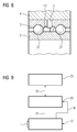
- the sensor 5 is formed flat and embedded in a film 29 (see FIG. 6 ) or on a slide (see FIG. 7 ) arranged.
- the sensor 5 thus forms, together with the film 29, a so-called sensor film.
- the sensor 5 measures the force F in the exemplary embodiment.
- the sensor film is shown in the illustration FIG. 1 for the sake of clarity, not to scale, but shown much thicker compared to reality.
- the measured force F is then, as already described above, read in the context of the embodiment of the control device 7.
- the sensor film could also, with appropriate design of the sensor, for example, measure the temperature, vibration or pressure, with different sensors for measuring different physical quantities (eg temperature sensor and force sensor) embedded in a common film or arranged on a common film can.
- FIG. 2 is a sectional view of the backup bearing and the bearing support 4 is shown, wherein in FIG. 2 the same elements are provided with the same reference numerals as in FIG. 1 , In the embodiment of the invention according to FIG. 1 and FIG. 2 the inner ring 2 slides directly in the outer ring 3.
- the fishing camp is thus designed as a plain bearing.
- FIG. 3 illustrated embodiment corresponds in basic construction substantially the above in FIG. 1 and FIG. 2 described embodiment. Same elements are therefore in FIG. 3 provided with the same reference numerals as in FIG. 1 and FIG. 2 , The only essential difference is that in the embodiment according to FIG. 3 between the outer ring 3 and inner ring 2 rolling elements 27 are arranged, which are formed in the embodiment in the form of balls. In the context of the embodiment according to FIG. 3 the fishing camp is designed in such a way as a rolling bearing.
- FIG. 4 is shown in a schematic representation of a further embodiment of the invention, which substantially according to the embodiment FIG. 3 corresponds, wherein the same elements are provided with the same reference numerals as in FIG. 3 ,
- the sensor 5 is not formed in the form of a sensor film, but as a conventional force sensor.
- the outer ring 3 On its side facing the safety bearing carrier 4, the outer ring 3 has a recess 13 in which at least part of the sensor 5 is arranged.
- the sensor 5 is at its top on Catch support 4 and arranged on its underside on the outer ring 3. In this way, the sensor 5 is arranged between the outer ring 3 and the backup bearing carrier 4 and measures the force F. occurring between the outer ring and the backup bearing carrier 4.
- the sensor 5 can however also be designed, for example, as a temperature sensor for measuring the temperature of the backup bearing or as a vibration sensor for measuring vibrations of the backup bearing be present or as a pressure sensor for measuring the pressure occurring between the outer ring and the backup bearing carrier.
- the sensor 5 is preferably arranged completely in the recess 13, ie it does not project beyond the recess 5, as in FIG FIG. 4 drawn.
- the sensor may be formed as a sensor film, wherein at least a part of the sensor of the sensor film or the sensor film can be arranged completely in the recess 13.
- FIG. 8 is shown in a schematic representation of a further embodiment of the invention, which substantially according to the embodiment FIG. 3 corresponds, wherein the same elements are provided with the same reference numerals as in FIG. 3 ,
- the sensor 5 is not formed in the form of a sensor film, but as a conventional displacement sensor for measuring the distance d between the outer ring 3 and inner ring 2.
- the outer ring 3 has in the context of this embodiment on its inner side a recess 13 ', wherein in According to the embodiment, part of the sensor 5 is arranged in the recess 13 'and part of the sensor 5 is arranged in the interior of the outer ring 3.
- the sensor 5 may also be arranged completely inside the outer ring 3.
- the sensor 5 formed as a displacement sensor in the context of this exemplary embodiment can also be arranged at a different location.
- the lines which lead away from the sensor 5 for transmitting the physical quantity are preferably passed through the backup bearing carrier 4, which is not shown in the figures for the sake of clarity.
- the outer ring 3 according to the embodiment of the invention according to FIG. 4 and FIG. 8 have a recess in which at least a part of the sensor 5 or the sensor 5 is completely arranged.
- FIG. 5 the inventive method for monitoring the condition of the backup bearing is shown in the form of a flow chart.
- the magnetic bearing 6 in a first step 15, the magnetic bearing 6 is turned off, then in a second step 16, the rotor shaft 1 rotates with a defined sequence of movements, by means of the sensor 5, a physical size G of the backup bearing 14 is measured and stored, then, in a third step 17, the measured physical quantity is compared with a desired value and, if appropriate, a warning message is generated in a fourth step 18, if the deviation of the measured physical quantity G from the setpoint exceeds a limit value.
- the magnetic bearing 6 is preferably switched off when the rotor shaft 1 is stationary.
- the switching off of the magnetic bearing 6 is performed by the control device 7 within the scope of the exemplary embodiment. Then the rotor shaft 1 falls into the fishing camp 14 and is caught by this. Subsequently, the rotor shaft 1 is rotated in a step 16 with a defined sequence of movements. Such a defined sequence of movements may be, for example, that the rotor shaft 1 rotates slowly at a predetermined constant speed over a certain period of time in the backup bearing 14. The rotor shaft is driven accordingly by the machine 12, which is from a higher-level controller 23 (see FIG. 1 and FIG. 9 ), which may be in the form of the numerical control of the machine 12, is controlled. The parent Control 23 controls this, as shown schematically in FIG FIG.
- a drive device 30 which includes a control device and a power supply to the machine 12 need converter, the machine 1 formed in the embodiment as an electric motor, to.
- the drive device 30 is connected to the machine 1 via electrical lines 31, which are illustrated schematically in the form of a dash.
- the drive device 30 is transmitted from a measuring device integrated in the machine 12 to the rotational angle W of the rotor shaft 1.
- the rotational speed with which the rotor shaft 1 is to rotate is predetermined to the drive device 30 by the higher-level controller 23 via a data connection 32 (eg data bus).
- a physical quantity such as the temperature of the backup bearing or occurring between the outer ring and the backup bearing carrier force F or the vibrations of the backup bearing or occurring between the outer ring and the backup bearing carrier pressure or the distance between the outer ring and inner ring measured and stored, the storage of physical size is preferably carried out in the control device 7.
- the measured physical variable can then be read and evaluated by an operator on site at the machine, for example.
- the temporal course of the physical variable can be represented for this purpose, for example in the form of a diagram on an operating device 24 of the machine.
- the operating device 24 is connected via the higher-order control 23 to the control device 7 for the transmission of data, which is illustrated by the arrows 25 and 26.
- the physical variable which is in the form of temporally successive measured values, is transmitted by the control device 7 to the operating device 24 and evaluated there by an operator.
- the sensor transmits this, preferably at constant time intervals, the measured values to the control device 7.
- the control device 7 is connected via the Internet 10 and / or eg via a bus system to a computer 11 remote from the machine 12 for the transmission of data, which is indicated by two arrows 19 and 20 in FIG FIG. 1 is shown.
- the Internet or a bus system are examples of typical data connections.
- the physical variable that is to say, the measured values
- the control device 7 can also be initially transmitted via the connection 25 from the controller 7 to the higher-level controller 23 and from there via, for example, the Internet 10, to the computer 11 will transmit what is in FIG. 1 is shown by a dashed arrow.
- a step 17 the measured physical quantity, which is in the form of temporally successive measured values, is compared with a nominal value and if the deviation from the measured physical quantity and nominal value exceeds a limit value, a warning message is generated in a step 18.
- the physical variable is usually present in the form of temporally successive measured measured values.
- the desired size can be determined, for example, by rotating the rotor shaft 1 with the defined sequence of movements in a newly installed safety bearing when the magnetic bearing is switched off, and in this case the physical quantity is measured and stored as the desired value.
- the setpoint is thus usually in the form of successive, preferably by a single measurement, determined setpoints.
- a warning message is generated in a step 18, depending on where the evaluation is realized, by the higher-level controller 23 or the control device 7 or the computer 11.
- the deviation may e.g. be determined by the amount of the difference of the measured values is determined to the setpoints.
- the alert message reports to the operator on site and / or maintenance personnel removed from the machine a severely worn backup bearing that needs to be replaced.
- the measured physical quantity and the target size are, as already mentioned, usually in the form of temporal progressions. Wear of a backup bearing generally affects e.g. to the effect that during the defined sequence of movements, the temperature of the backup bearing increases faster and / or higher temperature values are achieved than with an unworn fishing camp.
- the measured force and the measured pressure which occurs between the outer ring of the backup bearing and the backup bearing carrier and / or the distance between the outer ring and inner ring, and usually in a worn fishing camp over an untapped fishing camp, when performing the defined sequence of movements, and / or or there are unusual or stronger vibrations of the backup camp.
- the force F measured by the sensor 5 is evaluated as described above as a physical variable as described above and optionally generates a warning message.
- the force occurring between the outer ring 3 and the backup bearing carrier not only in the radial direction, as in FIG. 1 but also in the tangential direction, ie in the direction of the rotational movement of the rotor shaft 1.
- the sensor 5 can also be designed so that it measures the force acting in the direction of rotation of the rotor shaft 1 force.
- a variable derived from the physical quantity can be determined and then compared with a desired quantity, wherein if the deviation of the quantity derived from the physical quantity from the desired value exceeds a limit value, a warning message is generated.
- the quantity derived from the physical quantity may, for example, be in the form of the torque which is determined from the force acting in the direction of the rotational movement of the rotor shaft 1 and the distance of the sensor from the axis of rotation R by multiplying the two variables.
- the target size is correspondingly in the form of a torque in this case.
- variables can also be guided by other physical variables (eg temperature, vibrations) and compared with a corresponding desired value for evaluation.
- the force F can be derived from the measured distance d between the outer ring 3 and inner ring 2.
- the machine can also have a plurality of sensors for measuring different physical quantities.
- the machine can also simultaneously a sensor, the temperature of the backup bearing and / or a sensor of the occurring between the outer ring and the backup bearing carrier force and / or a sensor, the vibrations of the backup bearing and / or a sensor between the outer ring and the thrust bearing support occurring pressure and / or a sensor which measures the distance between the outer ring and inner ring have.
- the respective sensor can be arranged corresponding to the sensor 5, for example on the side facing the safety bearing carrier side of the outer ring and in particular at least partially or completely in the recess 13 of the outer ring 3 and / or between the outer ring and the safety bearing carrier and / or at least partially in the interior the outer ring 3, be arranged.
- the measured physical quantities are preferably evaluated in parallel, with each measured physical variable, for example as in FIG. 5 and the associated description is evaluated.
- the inventive method allows for predictive maintenance. Furthermore, by means of the method according to the invention, the catching bearing can also be monitored remotely by maintenance personnel without requiring maintenance personnel to go to the machine on site.
Landscapes
- Engineering & Computer Science (AREA)
- General Engineering & Computer Science (AREA)
- Mechanical Engineering (AREA)
- Physics & Mathematics (AREA)
- General Physics & Mathematics (AREA)
- Chemical & Material Sciences (AREA)
- Analytical Chemistry (AREA)
- Electromagnetism (AREA)
- Power Engineering (AREA)
- Magnetic Bearings And Hydrostatic Bearings (AREA)
- Rolling Contact Bearings (AREA)
Claims (15)
- Procédé de contrôle de l'état d'un palier (14) de secours d'une machine (12), dans lequel, si un palier (6) magnétique de la machine (12) est défaillant, on prend un arbre (1) de rotor par le palier (14) de secours, le palier (14) de secours ayant une bague (3) extérieure et une bague (2) intérieure montée tournante par rapport à la bague (3) extérieure, dans lequel, pour contrôler l'état du palier (14) de secours, on met hors circuit le palier (6) magnétique, on met en rotation l'arbre (1) du rotor à un déroulement de mouvement défini, on entraîne l'arbre (1) du rotor à cet effet d'une manière adéquate par la machine (12), ce qui est commandé par une commande (23) supérieure hiérarchiquement, et on mesure à l'aide d'un capteur (5) une grandeur (G) physique du palier (14) de secours.
- Procédé suivant la revendication 1, caractérisé en ce que l'on compare la grandeur (G) physique ou une grandeur déduite de la grandeur physique à une grandeur de consigne et, si l'écart de la grandeur (G) physique ou de la grandeur déduite à la grandeur de consigne dépasse une valeur limite, il est produit une alerte.
- Procédé suivant l'une des revendications précédentes, caractérisé en ce qu'un porte-palier de secours (4) est monté autour de la bague (3) extérieure pour fixer le palier (14) de secours dans la machine (12), le capteur (5) étant monté du côté de la bague (3) extérieure, tourné vers le porte-palier de secours (4).
- Procédé suivant l'une des revendications précédentes, caractérisé en ce que la grandeur (G) physique se présente sous la forme de la température du palier (14) de secours, sous la forme d'une force (F) se produisant entre la bague (3) extérieure et le porte-palier de secours (4), sous la forme de vibrations du palier (14) de secours ou sous la forme d'une pression se produisant entre la bague (3) extérieure et le porte-palier de secours (4).
- Procédé suivant l'une des revendications précédentes, caractérisé en ce que le capteur (5) est monté entre la bague (3) extérieure et le porte-palier de secours (4).
- Procédé suivant l'une des revendications précédentes, caractérisé en ce que le capteur (5) est constitué de manière plate et est incorporé dans une feuille (29) où est mis sur une feuille (29).
- Procédé suivant l'une des revendications précédentes, caractérisé en ce qu'un porte-palier de secours (4) est monté autour de la bague (3) extérieure pour fixer le palier (14) de secours dans la machine (12), la bague (3) extérieure ayant, sur son côté tourné vers le porte-palier de secours (4), un évidement (13) dans lequel est disposée au moins une partie du capteur (5).
- Procédé suivant la revendication 1 ou 2, caractérisé en ce que la grandeur (G) physique se présente sous la forme de la distance (d) entre la bague (3) extérieure et la bague (2) intérieure.
- Procédé suivant la revendication 8, caractérisé en ce qu'au moins une partie du capteur (5) est disposée à l'intérieur de la bague (3) extérieure.
- Procédé suivant l'une des revendications précédentes, caractérisé en ce que des corps (27) de roulement sont disposés entre la bague (3) extérieure et la bague (2) intérieure ou en ce que la bague (2) intérieure glisse directement dans la bague (3) extérieure.
- Procédé suivant l'une des revendications précédentes, caractérisé en ce que l'on transmet la grandeur (G) physique par une liaison (10, 19, 20) de données à un ordinateur (11) éloigné de la machine (12).
- Procédé suivant l'une des revendications précédentes, caractérisé en ce que la machine (12) est sous la forme d'un moteur électrique ou d'une génératrice ou d'un compresseur ou d'un condenseur ou d'une turbine.
- Procédé suivant la revendication 12, caractérisé en ce que la machine (12) est sous la forme d'une éolienne.
- Machine, la machine (12) ayant un palier (6) magnétique et un palier (14) de secours, le palier (14) de secours prenant un arbre (1) du rotor de la machine (12) si le palier (6) magnétique est défaillant, le palier (14) de secours ayant une bague (3) extérieure et une bague (2) intérieure montée tournante par rapport à la bague (3) extérieure, dans laquelle, pour contrôler l'état du palier (14) de secours, le palier (6) magnétique peut être mis hors circuit, l'arbre (1) du rotor peut, alors que le palier (6) magnétique est mis hors circuit, être mis en rotation à un déroulement du mouvement défini, l'arbre (1) du rotor pouvant être entraîné à cet effet d'une manière adéquate par la machine (12), ce qui peut être commandé par une commande (23) supérieure hiérarchiquement, la machine a un capteur (5) par lequel une grandeur (G) physique du palier (14) de secours peut être mesurée.
- Machine suivant la revendication 14, caractérisée en ce que la grandeur (G) physique peut être comparée à une grandeur de consigne ou à une grandeur déduite de la grandeur (G) physique et, si l'écart de la grandeur (G) physique ou de la grandeur déduite à la grandeur de consigne dépasse une valeur limite, une alerte peut être produite.
Applications Claiming Priority (2)
| Application Number | Priority Date | Filing Date | Title |
|---|---|---|---|
| DE102009022835A DE102009022835B3 (de) | 2009-05-27 | 2009-05-27 | Verfahren zur Überwachung des Zustands eines Fanglagers einer Maschine |
| PCT/EP2010/055046 WO2010136264A1 (fr) | 2009-05-27 | 2010-04-16 | Machine et procédé de surveillance de l'état d'un palier de secours d'une machine |
Publications (2)
| Publication Number | Publication Date |
|---|---|
| EP2435809A1 EP2435809A1 (fr) | 2012-04-04 |
| EP2435809B1 true EP2435809B1 (fr) | 2016-08-10 |
Family
ID=42352251
Family Applications (1)
| Application Number | Title | Priority Date | Filing Date |
|---|---|---|---|
| EP10718521.7A Active EP2435809B1 (fr) | 2009-05-27 | 2010-04-16 | Machine et procédé de surveillance de l'état d'un palier de secours d'une machine |
Country Status (8)
| Country | Link |
|---|---|
| US (2) | US9279735B2 (fr) |
| EP (1) | EP2435809B1 (fr) |
| CN (1) | CN102597728B (fr) |
| BR (1) | BRPI1012837A2 (fr) |
| CA (1) | CA2763582C (fr) |
| DE (1) | DE102009022835B3 (fr) |
| RU (1) | RU2504701C2 (fr) |
| WO (1) | WO2010136264A1 (fr) |
Cited By (2)
| Publication number | Priority date | Publication date | Assignee | Title |
|---|---|---|---|---|
| CN107532969A (zh) * | 2015-04-30 | 2018-01-02 | 日本精工株式会社 | 异常诊断系统 |
| EP3562001A1 (fr) | 2018-04-27 | 2019-10-30 | Siemens Aktiengesellschaft | Procédé de stockage magnétique d'un rotor |
Families Citing this family (31)
| Publication number | Priority date | Publication date | Assignee | Title |
|---|---|---|---|---|
| DE102009022835B3 (de) * | 2009-05-27 | 2011-03-03 | Schaeffler Kg | Verfahren zur Überwachung des Zustands eines Fanglagers einer Maschine |
| CA2763218A1 (fr) * | 2009-07-22 | 2011-01-27 | Johnson Controls Technology Company | Appareil et procede pour determiner le jeu dans des paliers mecaniques de secours de turbomachines employant des paliers electromagnetiques |
| WO2012123010A1 (fr) * | 2011-03-11 | 2012-09-20 | Aktiebolaget Skf | Dispositif pour renfermer un palier comportant un système pour détecter la charge appliquée au palier |
| CN102261994B (zh) * | 2011-05-05 | 2013-12-25 | 洛阳Lyc轴承有限公司 | 特大型转盘轴承性能试验机 |
| DE102011075768A1 (de) | 2011-05-12 | 2012-11-15 | Schaeffler Technologies AG & Co. KG | Fanglager |
| WO2012168757A1 (fr) * | 2011-06-10 | 2012-12-13 | Aktiebolaget Skf (Publ) | Dispositif de palier comprenant un boîtier déformable et un capteur |
| DE102012200440A1 (de) | 2012-01-12 | 2013-07-18 | Schaeffler Technologies AG & Co. KG | Lageranordnung |
| EP2808551B1 (fr) * | 2013-05-30 | 2020-01-08 | Nuovo Pignone S.r.l. | Machine tournante avec au moins un palier magnétique actif et des paliers de roulement auxiliaires |
| DE102013215244A1 (de) * | 2013-08-02 | 2015-02-05 | Siemens Aktiengesellschaft | Fanglager zum Auffangen einer Rotorwelle einer Maschine sowie Maschine |
| DE102014204025A1 (de) * | 2014-03-05 | 2015-09-10 | Schaeffler Technologies AG & Co. KG | Bauteil mit einem wenigstens einen Sensor aufweisenden Messelement |
| EP2918845B2 (fr) | 2014-03-11 | 2022-01-12 | Skf Magnetic Mechatronics | Machine rotative, roulement et procédé de fabrication d'une machine rotative |
| GB201419214D0 (en) * | 2014-10-29 | 2014-12-10 | Rolls Royce Plc | Bearing apparatus |
| CN104502105B (zh) * | 2015-01-04 | 2017-07-28 | 哈尔滨工业大学 | 一种滑动轴承实验台 |
| US20170213118A1 (en) * | 2016-01-22 | 2017-07-27 | Aktiebolaget Skf | Sticker, condition monitoring system, method & computer program product |
| US10019886B2 (en) | 2016-01-22 | 2018-07-10 | Aktiebolaget Skf | Sticker, condition monitoring system, method and computer program product |
| EP3203191A1 (fr) * | 2016-02-03 | 2017-08-09 | Siemens Aktiengesellschaft | Capteur de palier magnetique |
| JP6407905B2 (ja) * | 2016-03-11 | 2018-10-17 | ファナック株式会社 | 主軸軸受保護装置及びそれを備えた工作機械 |
| CN106198022B (zh) * | 2016-08-11 | 2018-10-30 | 大连三环复合材料技术开发股份有限公司 | 自润滑关节轴承运行状态监测装置及在线监测系统 |
| DE102016221610A1 (de) * | 2016-11-04 | 2018-05-09 | Schaeffler Technologies AG & Co. KG | Abstandsmessmodul zur Messung eines Abstandes in einem Lager sowie Sensorsatz und Lageranordnung |
| DE102017208128A1 (de) | 2017-05-15 | 2018-11-15 | Man Diesel & Turbo Se | Kompressor |
| PL3444585T3 (pl) * | 2017-08-17 | 2020-11-16 | Alstom Transport Technologies | Sposób określania stanu łożyska, moduł do określania stanu łożyska, pojazd szynowy i system |
| JP7052674B2 (ja) * | 2017-11-09 | 2022-04-12 | 日本製鉄株式会社 | 荷重測定ユニットおよび荷重測定方法 |
| CN108344534B (zh) * | 2018-02-07 | 2020-04-14 | 哈尔滨工业大学 | 一种复合载荷下轴承摩擦力矩测试装置和方法 |
| EP3663011A1 (fr) | 2018-12-05 | 2020-06-10 | Primetals Technologies Austria GmbH | Détection et transfert de données d'une installation de stockage d'une aciérie ou d'un laminoir |
| EP3702633A1 (fr) * | 2019-02-28 | 2020-09-02 | Siemens Aktiengesellschaft | Surveillance d'un palier de retenue |
| DE102019116999A1 (de) * | 2019-06-25 | 2020-12-31 | Schaeffler Technologies AG & Co. KG | Rollenlageranordnung zum Bestimmen von Belastungen |
| FR3108692B1 (fr) * | 2020-03-24 | 2022-06-24 | Skf Magnetic Mechatronics | Système de compensation des efforts appliqués sur un palier supportant un arbre de rotor d’une machine tournante |
| CN111811387B (zh) * | 2020-06-30 | 2021-11-26 | 中国电子科技集团公司第十六研究所 | 一种旋转状态下的轴承内外圈之间电阻的测量装置 |
| CN113375937B (zh) * | 2021-08-16 | 2021-11-05 | 天津飞旋科技股份有限公司 | 一种磁悬浮轴承的保护轴承的检测方法和装置 |
| EP4210203A1 (fr) | 2022-01-08 | 2023-07-12 | General Electric Renovables España S.L. | Machines électriques et procédés pour atténuer les courants de paliers |
| FI130959B1 (fi) | 2022-03-28 | 2024-06-18 | Spindrive Oy | Valvontajärjestelmä ja menetelmä magneettisesti kannateltavan kohteen turvalaakerien kunnon valvomiseksi |
Family Cites Families (38)
| Publication number | Priority date | Publication date | Assignee | Title |
|---|---|---|---|---|
| US3108264A (en) * | 1957-07-08 | 1963-10-22 | Heinoo Lauri | Bearing wear sensor |
| US3183043A (en) * | 1962-10-18 | 1965-05-11 | Westinghouse Electric Corp | Fail-safe bearing structure |
| US3508241A (en) * | 1967-09-06 | 1970-04-21 | Bendix Corp | Bearing failure sensing device |
| FR2630792B1 (fr) * | 1988-04-29 | 1992-03-06 | Mecanique Magnetique Sa | Palier auxiliaire a stator en graphite pour arbre tournant monte sur paliers magnetiques |
| SU1739100A1 (ru) * | 1990-03-11 | 1992-06-07 | Уральский политехнический институт им.С.М.Кирова | Устройство автоматического управлени пространственным положением быстровращающегос ротора |
| US5602437A (en) * | 1994-07-27 | 1997-02-11 | Lucas Aerospace Power Equipment Corporation | Bearing failure detector for electric generator |
| DE19522543A1 (de) | 1994-08-01 | 1996-02-08 | Ntn Toyo Bearing Co Ltd | Piezoelektrisches Film-Meßfühlersystem für Lager |
| KR960030515A (ko) * | 1995-01-24 | 1996-08-17 | 이형도 | 능동 자기 베어링 시스템 |
| JPH08277845A (ja) * | 1995-04-03 | 1996-10-22 | Shinko Electric Co Ltd | 軸受荷重の制御装置 |
| US5588754A (en) * | 1995-12-29 | 1996-12-31 | United Technologies Automotive, Inc. | Backup bearings for extreme speed touch down applications |
| US5642944A (en) * | 1996-03-06 | 1997-07-01 | W. L. Dublin, Jr. | Auxiliary bearing system |
| US5998894A (en) * | 1998-08-04 | 1999-12-07 | Pacific Scientific | Modular bearing failure sensor for an electrical generator |
| US6100809A (en) * | 1998-11-24 | 2000-08-08 | Alliedsignal Inc. | Bearing wear detection system |
| US6529135B1 (en) * | 1999-10-12 | 2003-03-04 | Csi Technology, Inc. | Integrated electric motor monitor |
| US6535135B1 (en) * | 2000-06-23 | 2003-03-18 | The Timken Company | Bearing with wireless self-powered sensor unit |
| DE10135784B4 (de) * | 2000-07-26 | 2015-09-17 | Ntn Corp. | Mit einem Rotationssensor versehenes Lager sowie mit diesem ausgerüsteter Motor |
| US7034711B2 (en) * | 2001-08-07 | 2006-04-25 | Nsk Ltd. | Wireless sensor, rolling bearing with sensor, management apparatus and monitoring system |
| EP1615091B1 (fr) * | 2003-02-14 | 2013-04-24 | NTN Corporation | Composant de machine utilisant une etiquette a puce et son procede de controle de la qualite et systeme de detection d'anomalie |
| JP2005084962A (ja) * | 2003-09-09 | 2005-03-31 | Ntn Corp | Icタグ付き機械要素部品 |
| JP2005092704A (ja) * | 2003-09-19 | 2005-04-07 | Ntn Corp | ワイヤレスセンサシステムおよびワイヤレスセンサ付軸受装置 |
| US7409319B2 (en) * | 2003-11-24 | 2008-08-05 | General Electric Company | Method and apparatus for detecting rub in a turbomachine |
| US6794777B1 (en) * | 2003-12-19 | 2004-09-21 | Richard Benito Fradella | Robust minimal-loss flywheel systems |
| US8430363B2 (en) | 2004-12-06 | 2013-04-30 | Progress Rail Services Corp | Train wheel bearing temperature detection |
| US7391128B2 (en) * | 2004-12-30 | 2008-06-24 | Rozlev Corp., Llc | Wind generator system using attractive magnetic forces to reduce the load on the bearings |
| DE102005004862A1 (de) * | 2005-02-02 | 2006-08-10 | Siemens Ag | Verfahren zur Überwachung der Temperatur zumindest eines Lagers einer elektrischen Maschine, eine hiermit korrespondierende Überwachungseinrichtung sowie elektrische Maschine mit einer derartigen Überwachungseinrichtung |
| DE102005032184A1 (de) * | 2005-07-09 | 2007-01-18 | Saurer Gmbh & Co. Kg | Verfahren zum Betreiben eines elektromotorischen Antriebs |
| ATE483114T1 (de) * | 2005-08-24 | 2010-10-15 | Mecos Traxler Ag | Magnetlagereinrichtung mit verbesserter gehäusedurchführung bei vakuum |
| FR2893106B1 (fr) * | 2005-11-09 | 2008-01-04 | Snr Roulements Sa | Roulement capteur de deformations comprenant au moins trois jauges de contrainte |
| WO2007066473A1 (fr) * | 2005-12-09 | 2007-06-14 | Ntn Corporation | Dispositif a palier magnetique |
| JP2007187461A (ja) * | 2006-01-11 | 2007-07-26 | Ntn Corp | 軸受試験装置 |
| DE102006019873B3 (de) * | 2006-04-28 | 2007-10-18 | Siemens Ag | Fanglager für eine elektrische Maschine sowie elektrische Maschine mit zumindest einem derartigen Fanglager |
| FI119033B (fi) | 2006-05-09 | 2008-06-30 | Metso Paper Inc | Sovitelma, järjestelmä ja menetelmä rainanmuodostus- tai jälkikäsittelykoneella pyörivän kappaleen toimintaolosuhteiden mittaamiseksi |
| US7421349B1 (en) * | 2006-05-15 | 2008-09-02 | United States Of America As Represented By The Secretary Of The Navy | Bearing fault signature detection |
| DE102007036692A1 (de) | 2006-09-22 | 2008-03-27 | Ebm-Papst St. Georgen Gmbh & Co. Kg | Lüfter |
| FR2908183B1 (fr) * | 2006-11-07 | 2009-01-23 | Univ Reims Champagne Ardenne | Dispositif et procede de surveillance de l'etat vibratoire d'une machine tournante |
| CN201212851Y (zh) * | 2008-04-10 | 2009-03-25 | 孙连贵 | 一种圆锥滚子轴承震动自动测量仪 |
| US9618037B2 (en) * | 2008-08-01 | 2017-04-11 | Honeywell International Inc. | Apparatus and method for identifying health indicators for rolling element bearings |
| DE102009022835B3 (de) * | 2009-05-27 | 2011-03-03 | Schaeffler Kg | Verfahren zur Überwachung des Zustands eines Fanglagers einer Maschine |
-
2009
- 2009-05-27 DE DE102009022835A patent/DE102009022835B3/de active Active
-
2010
- 2010-04-16 EP EP10718521.7A patent/EP2435809B1/fr active Active
- 2010-04-16 CN CN201080022841.2A patent/CN102597728B/zh active Active
- 2010-04-16 RU RU2011153382/11A patent/RU2504701C2/ru active
- 2010-04-16 CA CA2763582A patent/CA2763582C/fr not_active Expired - Fee Related
- 2010-04-16 BR BRPI1012837-9A patent/BRPI1012837A2/pt not_active IP Right Cessation
- 2010-04-16 WO PCT/EP2010/055046 patent/WO2010136264A1/fr active Application Filing
- 2010-04-16 US US13/322,701 patent/US9279735B2/en active Active
-
2016
- 2016-02-02 US US15/013,530 patent/US10110088B2/en active Active
Cited By (2)
| Publication number | Priority date | Publication date | Assignee | Title |
|---|---|---|---|---|
| CN107532969A (zh) * | 2015-04-30 | 2018-01-02 | 日本精工株式会社 | 异常诊断系统 |
| EP3562001A1 (fr) | 2018-04-27 | 2019-10-30 | Siemens Aktiengesellschaft | Procédé de stockage magnétique d'un rotor |
Also Published As
| Publication number | Publication date |
|---|---|
| RU2504701C2 (ru) | 2014-01-20 |
| US9279735B2 (en) | 2016-03-08 |
| BRPI1012837A2 (pt) | 2018-06-19 |
| CN102597728A (zh) | 2012-07-18 |
| CA2763582C (fr) | 2015-08-25 |
| WO2010136264A1 (fr) | 2010-12-02 |
| DE102009022835B3 (de) | 2011-03-03 |
| RU2011153382A (ru) | 2013-07-10 |
| CA2763582A1 (fr) | 2010-12-02 |
| US20160146247A1 (en) | 2016-05-26 |
| EP2435809A1 (fr) | 2012-04-04 |
| CN102597728B (zh) | 2015-07-22 |
| US10110088B2 (en) | 2018-10-23 |
| US20120126648A1 (en) | 2012-05-24 |
Similar Documents
| Publication | Publication Date | Title |
|---|---|---|
| EP2435809B1 (fr) | Machine et procédé de surveillance de l'état d'un palier de secours d'une machine | |
| EP2174097B1 (fr) | Détecteur de rotation doté d'une surveillance de l'usure des paliers et procédé dans ce but | |
| EP1794449B1 (fr) | Procede pour faire fonctionner un dispositif pour regler l'angle de reglage d'une plaque et procede de reglage associe | |
| EP3359840B1 (fr) | Dispositif électrique de rattrapage d'usure d'un frein à disque, frein à disque associé et procédé de mesure et de réglage du jeu et de mesure de l'usure | |
| EP3050682B1 (fr) | Procédé et système de fonctionnement et/ou de surveillance d'une machine multiaxiale | |
| EP3674234B1 (fr) | Rouleau de transport motorisé à commande de bus | |
| EP3554772B1 (fr) | Surveillance anticollision d'un robot | |
| EP2536530B1 (fr) | Procédé pour commander un entraînement pivotant | |
| EP4143439A1 (fr) | Détection d'état sur des pompes à vis excentrique | |
| EP2804826A1 (fr) | Surveillance de la vitesse de déplacement d'une bande de matière | |
| WO2007079950A1 (fr) | Procédé pour contrôler une fonction de freinage d'un moteur de robot | |
| DE102012216209A1 (de) | Lageranordnung, Ventilator, Verfahren zum Führen einer Welle und Programm | |
| EP2535570A2 (fr) | Système d'orientation d'une éolienne | |
| DE102014100200A1 (de) | Verfahren und Einrichtung zum Betrieb einer Windkraftanlage | |
| EP3472459B1 (fr) | Procédé de surveillance d'un réglage de pales de rotor | |
| EP3356091A1 (fr) | Dispositif d'articulation | |
| EP2098929B1 (fr) | Procédé de fonctionnement pour une machine entraînée à l'aide d'un entraînement électrique dotée d'une reconnaissance d'état par l'intermédiaire de l'analyse de fréquence | |
| EP3179121B1 (fr) | Entrainement électrique et groupe de filage à bout ouvert avec l'entrainement électrique | |
| EP4039563A1 (fr) | Entraînement de direction pour un système de direction d'un véhicule automobile, procédé de fonctionnement d'un système d'entraînement de direction, système de direction pour un véhicule automobile et procédé de fonctionnement d'un système de direction | |
| EP3774064B1 (fr) | Procédé servant à surveiller un débit de lubrifiant pour une centrifugeuse | |
| WO2021219506A1 (fr) | Procédé de détection et d'évaluation d'un état de frottement au niveau d'une articulation, bras robotique et produit-programme informatique | |
| EP2192388B1 (fr) | Dispositif et procédé de reconnaissance d'une position déterminée comme erronée d'un élément rotatif d'un émetteur incrémentiel | |
| DE102022130278B4 (de) | Sensorsystem | |
| EP3273054B1 (fr) | Procede de determination d'une position de montage pour un entrainement rotatif dans une eolienne | |
| DE102022130859A1 (de) | Verfahren zum Betrieb eines Antriebssystems zur Vermeidung von Eingriffsstörungen in Spannungswellengetrieben |
Legal Events
| Date | Code | Title | Description |
|---|---|---|---|
| PUAI | Public reference made under article 153(3) epc to a published international application that has entered the european phase |
Free format text: ORIGINAL CODE: 0009012 |
|
| 17P | Request for examination filed |
Effective date: 20111110 |
|
| AK | Designated contracting states |
Kind code of ref document: A1 Designated state(s): AT BE BG CH CY CZ DE DK EE ES FI FR GB GR HR HU IE IS IT LI LT LU LV MC MK MT NL NO PL PT RO SE SI SK SM TR |
|
| DAX | Request for extension of the european patent (deleted) | ||
| RAP1 | Party data changed (applicant data changed or rights of an application transferred) |
Owner name: SIEMENS AKTIENGESELLSCHAFT |
|
| GRAP | Despatch of communication of intention to grant a patent |
Free format text: ORIGINAL CODE: EPIDOSNIGR1 |
|
| INTG | Intention to grant announced |
Effective date: 20160224 |
|
| GRAS | Grant fee paid |
Free format text: ORIGINAL CODE: EPIDOSNIGR3 |
|
| GRAA | (expected) grant |
Free format text: ORIGINAL CODE: 0009210 |
|
| AK | Designated contracting states |
Kind code of ref document: B1 Designated state(s): AT BE BG CH CY CZ DE DK EE ES FI FR GB GR HR HU IE IS IT LI LT LU LV MC MK MT NL NO PL PT RO SE SI SK SM TR |
|
| REG | Reference to a national code |
Ref country code: GB Ref legal event code: FG4D Free format text: NOT ENGLISH |
|
| REG | Reference to a national code |
Ref country code: CH Ref legal event code: EP Ref country code: AT Ref legal event code: REF Ref document number: 819492 Country of ref document: AT Kind code of ref document: T Effective date: 20160815 |
|
| REG | Reference to a national code |
Ref country code: IE Ref legal event code: FG4D Free format text: LANGUAGE OF EP DOCUMENT: GERMAN |
|
| REG | Reference to a national code |
Ref country code: DE Ref legal event code: R096 Ref document number: 502010012185 Country of ref document: DE |
|
| REG | Reference to a national code |
Ref country code: NL Ref legal event code: FP |
|
| REG | Reference to a national code |
Ref country code: LT Ref legal event code: MG4D |
|
| REG | Reference to a national code |
Ref country code: NO Ref legal event code: T2 Effective date: 20160810 |
|
| PG25 | Lapsed in a contracting state [announced via postgrant information from national office to epo] |
Ref country code: IS Free format text: LAPSE BECAUSE OF FAILURE TO SUBMIT A TRANSLATION OF THE DESCRIPTION OR TO PAY THE FEE WITHIN THE PRESCRIBED TIME-LIMIT Effective date: 20161210 Ref country code: HR Free format text: LAPSE BECAUSE OF FAILURE TO SUBMIT A TRANSLATION OF THE DESCRIPTION OR TO PAY THE FEE WITHIN THE PRESCRIBED TIME-LIMIT Effective date: 20160810 Ref country code: IT Free format text: LAPSE BECAUSE OF FAILURE TO SUBMIT A TRANSLATION OF THE DESCRIPTION OR TO PAY THE FEE WITHIN THE PRESCRIBED TIME-LIMIT Effective date: 20160810 Ref country code: FI Free format text: LAPSE BECAUSE OF FAILURE TO SUBMIT A TRANSLATION OF THE DESCRIPTION OR TO PAY THE FEE WITHIN THE PRESCRIBED TIME-LIMIT Effective date: 20160810 Ref country code: LT Free format text: LAPSE BECAUSE OF FAILURE TO SUBMIT A TRANSLATION OF THE DESCRIPTION OR TO PAY THE FEE WITHIN THE PRESCRIBED TIME-LIMIT Effective date: 20160810 |
|
| PG25 | Lapsed in a contracting state [announced via postgrant information from national office to epo] |
Ref country code: LV Free format text: LAPSE BECAUSE OF FAILURE TO SUBMIT A TRANSLATION OF THE DESCRIPTION OR TO PAY THE FEE WITHIN THE PRESCRIBED TIME-LIMIT Effective date: 20160810 Ref country code: PL Free format text: LAPSE BECAUSE OF FAILURE TO SUBMIT A TRANSLATION OF THE DESCRIPTION OR TO PAY THE FEE WITHIN THE PRESCRIBED TIME-LIMIT Effective date: 20160810 Ref country code: GR Free format text: LAPSE BECAUSE OF FAILURE TO SUBMIT A TRANSLATION OF THE DESCRIPTION OR TO PAY THE FEE WITHIN THE PRESCRIBED TIME-LIMIT Effective date: 20161111 Ref country code: SE Free format text: LAPSE BECAUSE OF FAILURE TO SUBMIT A TRANSLATION OF THE DESCRIPTION OR TO PAY THE FEE WITHIN THE PRESCRIBED TIME-LIMIT Effective date: 20160810 Ref country code: ES Free format text: LAPSE BECAUSE OF FAILURE TO SUBMIT A TRANSLATION OF THE DESCRIPTION OR TO PAY THE FEE WITHIN THE PRESCRIBED TIME-LIMIT Effective date: 20160810 Ref country code: PT Free format text: LAPSE BECAUSE OF FAILURE TO SUBMIT A TRANSLATION OF THE DESCRIPTION OR TO PAY THE FEE WITHIN THE PRESCRIBED TIME-LIMIT Effective date: 20161212 |
|
| PG25 | Lapsed in a contracting state [announced via postgrant information from national office to epo] |
Ref country code: RO Free format text: LAPSE BECAUSE OF FAILURE TO SUBMIT A TRANSLATION OF THE DESCRIPTION OR TO PAY THE FEE WITHIN THE PRESCRIBED TIME-LIMIT Effective date: 20160810 Ref country code: EE Free format text: LAPSE BECAUSE OF FAILURE TO SUBMIT A TRANSLATION OF THE DESCRIPTION OR TO PAY THE FEE WITHIN THE PRESCRIBED TIME-LIMIT Effective date: 20160810 |
|
| REG | Reference to a national code |
Ref country code: DE Ref legal event code: R097 Ref document number: 502010012185 Country of ref document: DE |
|
| PG25 | Lapsed in a contracting state [announced via postgrant information from national office to epo] |
Ref country code: BG Free format text: LAPSE BECAUSE OF FAILURE TO SUBMIT A TRANSLATION OF THE DESCRIPTION OR TO PAY THE FEE WITHIN THE PRESCRIBED TIME-LIMIT Effective date: 20161110 Ref country code: SK Free format text: LAPSE BECAUSE OF FAILURE TO SUBMIT A TRANSLATION OF THE DESCRIPTION OR TO PAY THE FEE WITHIN THE PRESCRIBED TIME-LIMIT Effective date: 20160810 Ref country code: CZ Free format text: LAPSE BECAUSE OF FAILURE TO SUBMIT A TRANSLATION OF THE DESCRIPTION OR TO PAY THE FEE WITHIN THE PRESCRIBED TIME-LIMIT Effective date: 20160810 Ref country code: DK Free format text: LAPSE BECAUSE OF FAILURE TO SUBMIT A TRANSLATION OF THE DESCRIPTION OR TO PAY THE FEE WITHIN THE PRESCRIBED TIME-LIMIT Effective date: 20160810 Ref country code: SM Free format text: LAPSE BECAUSE OF FAILURE TO SUBMIT A TRANSLATION OF THE DESCRIPTION OR TO PAY THE FEE WITHIN THE PRESCRIBED TIME-LIMIT Effective date: 20160810 |
|
| PLBE | No opposition filed within time limit |
Free format text: ORIGINAL CODE: 0009261 |
|
| STAA | Information on the status of an ep patent application or granted ep patent |
Free format text: STATUS: NO OPPOSITION FILED WITHIN TIME LIMIT |
|
| 26N | No opposition filed |
Effective date: 20170511 |
|
| PG25 | Lapsed in a contracting state [announced via postgrant information from national office to epo] |
Ref country code: SI Free format text: LAPSE BECAUSE OF FAILURE TO SUBMIT A TRANSLATION OF THE DESCRIPTION OR TO PAY THE FEE WITHIN THE PRESCRIBED TIME-LIMIT Effective date: 20160810 |
|
| REG | Reference to a national code |
Ref country code: CH Ref legal event code: NV Representative=s name: SIEMENS SCHWEIZ AG, CH Ref country code: CH Ref legal event code: PCOW Free format text: NEW ADDRESS: WERNER-VON-SIEMENS-STRASSE 1, 80333 MUENCHEN (DE) |
|
| REG | Reference to a national code |
Ref country code: CH Ref legal event code: PL |
|
| GBPC | Gb: european patent ceased through non-payment of renewal fee |
Effective date: 20170416 |
|
| REG | Reference to a national code |
Ref country code: IE Ref legal event code: MM4A |
|
| REG | Reference to a national code |
Ref country code: FR Ref legal event code: ST Effective date: 20171229 |
|
| PG25 | Lapsed in a contracting state [announced via postgrant information from national office to epo] |
Ref country code: MC Free format text: LAPSE BECAUSE OF FAILURE TO SUBMIT A TRANSLATION OF THE DESCRIPTION OR TO PAY THE FEE WITHIN THE PRESCRIBED TIME-LIMIT Effective date: 20160810 Ref country code: FR Free format text: LAPSE BECAUSE OF NON-PAYMENT OF DUE FEES Effective date: 20170502 |
|
| PG25 | Lapsed in a contracting state [announced via postgrant information from national office to epo] |
Ref country code: LI Free format text: LAPSE BECAUSE OF NON-PAYMENT OF DUE FEES Effective date: 20170430 Ref country code: LU Free format text: LAPSE BECAUSE OF NON-PAYMENT OF DUE FEES Effective date: 20170416 Ref country code: GB Free format text: LAPSE BECAUSE OF NON-PAYMENT OF DUE FEES Effective date: 20170416 Ref country code: CH Free format text: LAPSE BECAUSE OF NON-PAYMENT OF DUE FEES Effective date: 20170430 |
|
| REG | Reference to a national code |
Ref country code: BE Ref legal event code: MM Effective date: 20170430 |
|
| PG25 | Lapsed in a contracting state [announced via postgrant information from national office to epo] |
Ref country code: IE Free format text: LAPSE BECAUSE OF NON-PAYMENT OF DUE FEES Effective date: 20170416 |
|
| PG25 | Lapsed in a contracting state [announced via postgrant information from national office to epo] |
Ref country code: BE Free format text: LAPSE BECAUSE OF NON-PAYMENT OF DUE FEES Effective date: 20170430 |
|
| REG | Reference to a national code |
Ref country code: AT Ref legal event code: MM01 Ref document number: 819492 Country of ref document: AT Kind code of ref document: T Effective date: 20170416 |
|
| PG25 | Lapsed in a contracting state [announced via postgrant information from national office to epo] |
Ref country code: AT Free format text: LAPSE BECAUSE OF NON-PAYMENT OF DUE FEES Effective date: 20170416 |
|
| PG25 | Lapsed in a contracting state [announced via postgrant information from national office to epo] |
Ref country code: MT Free format text: LAPSE BECAUSE OF FAILURE TO SUBMIT A TRANSLATION OF THE DESCRIPTION OR TO PAY THE FEE WITHIN THE PRESCRIBED TIME-LIMIT Effective date: 20160810 |
|
| PG25 | Lapsed in a contracting state [announced via postgrant information from national office to epo] |
Ref country code: HU Free format text: LAPSE BECAUSE OF FAILURE TO SUBMIT A TRANSLATION OF THE DESCRIPTION OR TO PAY THE FEE WITHIN THE PRESCRIBED TIME-LIMIT; INVALID AB INITIO Effective date: 20100416 |
|
| PG25 | Lapsed in a contracting state [announced via postgrant information from national office to epo] |
Ref country code: CY Free format text: LAPSE BECAUSE OF NON-PAYMENT OF DUE FEES Effective date: 20160810 |
|
| PG25 | Lapsed in a contracting state [announced via postgrant information from national office to epo] |
Ref country code: MK Free format text: LAPSE BECAUSE OF FAILURE TO SUBMIT A TRANSLATION OF THE DESCRIPTION OR TO PAY THE FEE WITHIN THE PRESCRIBED TIME-LIMIT Effective date: 20160810 |
|
| PG25 | Lapsed in a contracting state [announced via postgrant information from national office to epo] |
Ref country code: TR Free format text: LAPSE BECAUSE OF FAILURE TO SUBMIT A TRANSLATION OF THE DESCRIPTION OR TO PAY THE FEE WITHIN THE PRESCRIBED TIME-LIMIT Effective date: 20160810 |
|
| REG | Reference to a national code |
Ref country code: DE Ref legal event code: R081 Ref document number: 502010012185 Country of ref document: DE Owner name: INNOMOTICS GMBH, DE Free format text: FORMER OWNER: SIEMENS AKTIENGESELLSCHAFT, 80333 MUENCHEN, DE |
|
| REG | Reference to a national code |
Ref country code: NL Ref legal event code: PD Owner name: INNOMOTICS GMBH; DE Free format text: DETAILS ASSIGNMENT: CHANGE OF OWNER(S), ASSIGNMENT; FORMER OWNER NAME: SIEMENS AKTIENGESELLSCHAFT Effective date: 20231124 |
|
| REG | Reference to a national code |
Ref country code: NO Ref legal event code: CHAD Owner name: INNOMOTICS GMBH, DE |
|
| PGFP | Annual fee paid to national office [announced via postgrant information from national office to epo] |
Ref country code: NL Payment date: 20240409 Year of fee payment: 15 |
|
| PGFP | Annual fee paid to national office [announced via postgrant information from national office to epo] |
Ref country code: DE Payment date: 20240619 Year of fee payment: 15 |
|
| PGFP | Annual fee paid to national office [announced via postgrant information from national office to epo] |
Ref country code: NO Payment date: 20240410 Year of fee payment: 15 |