EP2098929B1 - Procédé de fonctionnement pour une machine entraînée à l'aide d'un entraînement électrique dotée d'une reconnaissance d'état par l'intermédiaire de l'analyse de fréquence - Google Patents
Procédé de fonctionnement pour une machine entraînée à l'aide d'un entraînement électrique dotée d'une reconnaissance d'état par l'intermédiaire de l'analyse de fréquence Download PDFInfo
- Publication number
- EP2098929B1 EP2098929B1 EP08004287A EP08004287A EP2098929B1 EP 2098929 B1 EP2098929 B1 EP 2098929B1 EP 08004287 A EP08004287 A EP 08004287A EP 08004287 A EP08004287 A EP 08004287A EP 2098929 B1 EP2098929 B1 EP 2098929B1
- Authority
- EP
- European Patent Office
- Prior art keywords
- machine
- drive
- control device
- frequency
- sensor
- Prior art date
- Legal status (The legal status is an assumption and is not a legal conclusion. Google has not performed a legal analysis and makes no representation as to the accuracy of the status listed.)
- Active
Links
Images


Classifications
-
- G—PHYSICS
- G05—CONTROLLING; REGULATING
- G05B—CONTROL OR REGULATING SYSTEMS IN GENERAL; FUNCTIONAL ELEMENTS OF SUCH SYSTEMS; MONITORING OR TESTING ARRANGEMENTS FOR SUCH SYSTEMS OR ELEMENTS
- G05B19/00—Programme-control systems
- G05B19/02—Programme-control systems electric
- G05B19/18—Numerical control [NC], i.e. automatically operating machines, in particular machine tools, e.g. in a manufacturing environment, so as to execute positioning, movement or co-ordinated operations by means of programme data in numerical form
- G05B19/406—Numerical control [NC], i.e. automatically operating machines, in particular machine tools, e.g. in a manufacturing environment, so as to execute positioning, movement or co-ordinated operations by means of programme data in numerical form characterised by monitoring or safety
- G05B19/4065—Monitoring tool breakage, life or condition
-
- G—PHYSICS
- G05—CONTROLLING; REGULATING
- G05B—CONTROL OR REGULATING SYSTEMS IN GENERAL; FUNCTIONAL ELEMENTS OF SUCH SYSTEMS; MONITORING OR TESTING ARRANGEMENTS FOR SUCH SYSTEMS OR ELEMENTS
- G05B2219/00—Program-control systems
- G05B2219/30—Nc systems
- G05B2219/37—Measurements
- G05B2219/37252—Life of tool, service life, decay, wear estimation
-
- G—PHYSICS
- G05—CONTROLLING; REGULATING
- G05B—CONTROL OR REGULATING SYSTEMS IN GENERAL; FUNCTIONAL ELEMENTS OF SUCH SYSTEMS; MONITORING OR TESTING ARRANGEMENTS FOR SUCH SYSTEMS OR ELEMENTS
- G05B2219/00—Program-control systems
- G05B2219/30—Nc systems
- G05B2219/37—Measurements
- G05B2219/37435—Vibration of machine
Definitions
- the present invention further relates to a computer program comprising machine code which is directly executable by a control device for a drive-driven machine, wherein the execution of the machine code causes the control device to switch the drive via at least one actuator to a power supply and from a Sensor of the machine receives a time-dependent signal.
- the present invention relates to a data carrier on which such a computer program is stored in machine-readable form.
- the above objects are well known. Typical examples of such machines are drills, lathes, circular and band saws, and other machines.
- the drive is in many cases a rotating drive. In some cases, however, the drive may be designed as a linear drive.
- Machines usually have many individual components. Some of the components are rigid, others are flexible, but most are not moved and others are moved normally. Examples of rigid components are the main body of the machine and the cladding of the machine. An example of a rarely moved component is a cover, by means of which a processing area of the machine is covered. Movable parts are, for example, shafts, bearings and spindles.
- the individual components of the machine are subject to wear and other temporal changes. Some of these changes are harmless, some critical, some require immediate intervention in the operation to avoid consequential damage.
- the sensors used and in particular the evaluation circuits used are often expensive. Furthermore, it is often difficult to integrate the sensors and the evaluation circuits in the machine or in the electric drive. Furthermore, the sensors are often susceptible to interference. Also, the signal transmission is often difficult. Furthermore, in many cases, a single signal is not sufficient for a clear and reliable description of the system status. Furthermore, the coupling of external sensor signals or signals from evaluation circuits in a numerical control or in an inverter in many cases associated with considerable effort and beyond undesirable for technical reasons. Furthermore, faults and other process influences during operation often prevent a clear evaluation of the detected signals. Finally, meaningful and meaningful limit values for determining wear states can not always be reliably determined, since the individual components of the machine interact with one another.
- An operating method for a drive-driven machine is known.
- the drive of a control device via an actuator to a power supply can be connected.
- the drive is connected by the control device to the power supply in such a way that the drive excites the machine to vibrate directly or indirectly over a frequency range.
- a sensor becomes a time-dependent Detects signal that is characteristic of excited vibrations.
- the time-dependent signal is transmitted to the control device, which performs a frequency analysis of the time-dependent signal. Based on the frequency analysis, a state of at least one element of the machine is determined.
- the object of the present invention is to provide opportunities to be able to determine the condition of rolling bearings and other components of the machine in a cost-effective, simple and unambiguous manner.
- the drive is switched by a control device of the machine via at least one actuator to a power supply, so that the drive excites the machine directly or indirectly via a frequency range to vibrations.
- a time-dependent signal is detected, which is characteristic of excited vibrations.
- the time-dependent signal is transmitted to the control device.
- the control device performs a frequency analysis of the time-dependent signal.
- the frequency analysis is related by the controller to the vibration excitation and determines a state of at least one element of the machine. Depending on the determined state, the control device outputs a message to an operator of the machine.
- the drive will be acted upon by the control device with a disturbance variable which has at least one frequency lying within the frequency range.
- the disturbance is a sinusoidal disturbance whose frequency passes through the frequency range.
- This embodiment of the operating method leads to particularly reliable evaluations.
- the disturbance is a pseudo-binary disturbance whose spectrum covers the frequency range. This approach has the advantage that it is also applicable in normal operation of the machine.
- the drive is designed as a three-phase AC drive, it is possible to perform an asymmetrical energization or turn on a suitable excitation on the normal drive signal of the drive.
- the machine performs characteristic vibrations depending on the excitation. These can be detected by a corresponding sensor and evaluated by the control device.
- vibration is meant an oscillating mechanical movement of at least one element of the machine which is not a useful movement of the machine.
- the drive drives a shaft and a shaft via the shaft
- the rotation of the shaft and the displacement of the piston are the useful movements of the machine
- all other oscillating mechanical movements are vibrations.
- the vibration can be mono- or multifrequency.
- the transfer function of the machine is determined and evaluated.
- the transfer function describes the behavior of the machine on excitation, i. H. the relationship between an output or system response (excited vibrations) and an input or system excitation (driving the electric machine).
- the transfer function completely maps a system. From the transmission behavior of a system can thus be drawn conclusions about the state of individual components of the system. Furthermore, transfer functions always allow reliable evaluation of the overall behavior at the same time.
- the procedure according to the invention thus makes it possible to monitor and diagnose the machine.
- the excitation signal can be generated directly by the drive. There is no external stimulus required.
- the drive can optionally be designed as an electric, hydraulic or pneumatic drive. Usually it is designed as an electric drive.
- the at least one actuator can be switched to binary only by the control device.
- the at least one actuator can be controlled proportionally by the control device.
- the sensor can in principle be configured as desired, if it is only suitable for detecting the corresponding signal.
- the sensor may be designed as a displacement sensor, as a speed sensor, as an acceleration sensor, as a force sensor or as a pressure sensor.
- the signal detected by the sensor is characteristic only for the amplitude of the excited vibrations or only for the phase position of the excited vibrations. As a rule, however, the signal detected by the sensor will be characteristic for the amplitude and for the phase position of the excited vibrations.
- control device sets amplitude and / or phase position of the excited vibrations in relation to the amplitude and / or phase position of the vibration excitation. From this, the state of the at least one element of the machine is then determined.
- the disturbance may have the shapes described above.
- the execution of the machine code causes the control device additionally implements one of the advantageous embodiments of the operating method.
- the present invention is achieved by a data carrier on which such a computer program is stored in machine-readable form.
- control device for a device driven by a drive machine, wherein the control device is programmed with a computer program of the type described above, so that it is able to perform in operation the corresponding method steps.
- the control device of the machine is preferably designed such that it is able to carry out one of the advantageous refinements of the operating method during operation.
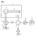
- a machine has a main body 1 and a shaft 2 rotatably mounted in the main body 1, for example a spindle shaft of a lathe.
- the spindle shaft 2 (or more generally the machine) is drivable by means of an electric drive 3.
- the electric drive 3 is usually a three-phase three-phase motor, which is fed via a converter 4 from a power grid 5.
- the machine does not have to be designed as a lathe, but it could be another machine.
- the drive 3 need not be a three-phase drive, but may be another electric drive. It must, strictly speaking, the drive 3 is not even designed as an electric drive. It could also be designed as a hydraulic or pneumatic drive. It is crucial that the drive 3 is capable of starting from a standstill when it is connected to the power supply 5 (or more generally a power supply) via the inverter 4 (or other suitable actuator or group of actuators). Also, it is not absolutely necessary to feed the electric drive 3 via a converter 4.
- the inverter 4 In the case of a hydraulic or pneumatic drive of course, the inverter 4 must be replaced by suitable other actuators, in particular by valves. Regardless of which type of drive is 3 (electric, hydraulic, pneumatic), it is possible that the corresponding actuator 4 (for example, the individual semiconductor switches of the inverter 4) are switched purely binary by the control device 6. Depending on the configuration of the actuators - but it is possible - in particular in hydraulic and pneumatic actuators 3 - alternatively, to control the actuators proportional.
- the machine also has a control device 6.
- the control device 6 controls the machine.
- the control device 6 depending on the configuration of the machine directly or indirectly via the inverter 4 - the electric drive 3 at. Furthermore, it receives from at least one sensor 7 of the machine a time-dependent signal S detected by the sensor 7.
- the control device 6 is designed as a software programmable control device. It therefore executes machine code 8 of a computer program 9 during operation, with which the control device 6 is programmed.
- the machine code 8 is thus directly executable by the control device 6.
- the execution of the machine code 8 causes the controller 6 to operate the machine in accordance with an operating method which will be described below in connection with FIGS FIG. 2 4 is explained in more detail.
- the computer program 9 may already have been deposited in the control device 6 during the production of the control device 6. Alternatively, it is possible to supply the computer program 9 to the control device 6 via a computer-computer connection.
- the calculator-computer connection is in FIG. 1 not shown here. It can be designed, for example, as a connection to a LAN or to the Internet. Again alternatively, it is possible to store the computer program 9 in machine-readable form on a data carrier 10 and to supply the computer program 9 to the control device 6 via the data carrier 10.
- the design of the data carrier 10 is arbitrary in nature. For example, it is possible that the data carrier 10 is designed as a USB memory stick or as a memory card. Is shown in FIG. 1 an embodiment of the data carrier 10 as a CD-ROM.
- a step S1 the control device 6 switches the drive 3 via the actuator 4 to the power supply 5 in such a way that the drive 3 excites the machine to vibrate over a frequency range F.
- the excitation to the vibrations here can alternatively be done directly or indirectly. This will be later in connection with the FIG. 3 and 4 will be discussed in more detail.
- the control device 6 receives the time-dependent signal S from the sensor 7.
- the time-dependent signal S is, of course, previously detected by the sensor 7 and transmitted to the control device 6.
- the signal S is characteristic of vibrations that have been excited due to the driving of the electric drive 3 in step S1.
- the vibrations have frequencies f, which correspond to those of the frequency range F.
- the signal S detected by the sensor 7 must be characteristic of the amplitude and / or the phase position of the excited vibrations. As a rule, the signal S detected by the sensor 7 is characteristic both for the amplitude and for the phase positions of the excited vibrations.
- the sensor 7 can be designed for this purpose in principle in any way, provided that it has the desired sensitivity.
- the sensor 7 may be formed as a displacement sensor, as a speed sensor, as an acceleration sensor, as a force sensor or as a pressure sensor.
- control device 6 performs a frequency analysis of the time-dependent signal S. For example, it can perform a Fourier transform.
- the controller 6 relates the frequency analysis of the step S3 to the vibration excitation.
- the control device 6 can set the amplitude and / or phase position of the individual excited vibrations in relation to the amplitude and / or phase position of the corresponding vibration excitation.
- step S5 based on the reference of step S4, the control device 6 determines a state of at least one element of the machine, for example the shaft 2, the main body 1, the drive 3 or a - FIG. 1 not shown - bearing of the shaft 2 in the main body. 1
- the determination of the state can be determined by the control device 6, for example, by determining the ratio of the amplitudes of the excited vibration and the vibration excitation for each frequency f, the phase offset of the excited vibration to the stimulating vibration and compares these values with reference values are stored in the control device 6. Depending on the result of the comparison can then be closed to the appropriate state.
- a step S6 the control device 6 outputs a message M to an operator 11 of the machine.
- the output message M is dependent on the state of the machine determined in step S5. For example, a warning message, an alarm message or a message that everything is OK can be output.
- FIG. 3 To excite the vibrations is according to FIG. 3 provided to impinge the drive 3 with a disturbance Z.
- the application of the disturbance Z takes place here - directly or indirectly via the inverter 4 - by the control device 6.
- This approach has the advantage that it can be executed without having to make modifications to the machine.
- the disturbance Z is hereby switched to a "normal" drive signal A of the drive 3.
- the disturbance Z has at least one frequency f, which lies within the frequency range F.
- the disturbance Z is a sinusoidal disturbance whose frequency f passes through the frequency range F.
- the disturbance Z is a pseudo-binary disturbance whose spectrum covers the frequency range F.
- the present invention has many advantages.
- a simple acceleration sensor or the like suffices for the judgment of the state of the machine.
- Temporal variations of the transmission behavior which can be caused for example by thermal or mechanical effects, can be clearly elaborated. It is possible to determine the condition of bearings.
Claims (15)
- Procédé pour faire fonctionner une machine entraînée au moyen d'un entraînement ( 3 ),- dans lequel l'entraînement ( 3 ) peut être branché par un dispositif ( 6 ) de commande sur une alimentation ( 5 ) en énergie par l'intermédiaire d'au moins un élément ( 4 ) de réglage,- dans lequel l'entraînement ( 3 ) est en mesure, lors du branchement sur l'installation ( 5 ) d'énergie, de se mettre en marche à partir de l'arrêt,- dans lequel l'entraînement ( 3 ) est branché par le dispositif ( 6 ) de commande sur l'alimentation ( 5 ) en énergie, de manière à ce que l'entraînement ( 3 ) excite en vibrations la machine directement ou indirectement sur un domaine ( F ) de fréquence,- dans lequel on détecte au moyen d'un capteur ( 7 ) un signal ( S ), qui dépend du temps et qui est caractéristique des vibrations excitées,- dans lequel on transmet le signal ( S ) qui dépend du temps au dispositif ( 6 ) de commande,- dans lequel une analyse de fréquence du signal qui dépend du temps est effectuée par le dispositif ( 6 ) de commande,- dans lequel l'analyse de fréquence par le dispositif ( 6 ) de commande est mise en relation avec l'excitation de vibrations et il en est déterminé un état d'au moins un élément ( 1 à 3 ) de la machine,- dans lequel il est envoyé, par le dispositif ( 6 ) de commande, en fonction de l'état déterminé, un message ( M ) à l'opérateur ( 11 ) de la machine,- dans lequel, pour l'excitation en Vibration, l'entraînement ( 3 ) est soumis par le dispositif ( 6 ) de commande à une grandeur ( Z ) de perturbation, qui a au moins une fréquence ( f ) se trouvant dans le domaine ( F ) de fréquence,- dans lequel la grandeur ( Z ) de perturbation est une grandeur de perturbation sinusoïdale, dont la fréquence ( f ) traverse le domaine ( F ) de fréquence ou la grandeur ( Z ) de perturbation est une grandeur de perturbation pseudobinaire, dont le spectre recouvre le domaine ( F ) de fréquence.
- Procédé suivant la revendication 1, caractérisé en ce que l'entraînement ( 3 ) est constitué sous la forme d'un entraînement ( 3 ) électrique, hydraulique ou pneumatique.
- Procédé suivant la revendication 1 ou 2, caractérisé en ce que le au moins un élément ( 4 ) de réglage n'est branché que binairement ou est commandé proportionnellement par le dispositif ( 6 ) de commande.
- Procédé suivant la revendication 1, 2 ou 3, caractérisé en ce que le capteur ( 7 ) est constitué sous la forme d'un capteur de trajet, sous la forme d'un capteur de vitesse, sous la forme d'un capteur d'accélération, sous la forme d'un capteur de force ou sous la forme d'un capteur de pression.
- Procédé suivant l'une des revendications précédentes, caractérisé en ce que le signal ( S ) détecté par le capteur ( 7 ) est caractéristique de l'amplitude et de la position en phase des vibrations excitées.
- Procédé suivant l'une des revendications précédentes, caractérisé en ce que le dispositif ( 6 ) de commande met l'amplitude et/ou la position en phase des vibrations excitées en rapport avec l'amplitude et/ou la position en phase de l'excitation en vibration et en détermine l'état du au moins un élément ( 1 à 3 ) de la machine.
- Programme informatique, le programme informatique comprenant un code ( 8 ) machine, qui peut être réalisé notamment par un dispositif ( 6 ) de commande d'une machine entraînée au moyen d'un entraînement ( 3 ), la réalisation du code machine ( 8 ) faisant que le dispositif ( 6 ) de commande- branche l'entraînement ( 3 ) sur une alimentation ( 5 ) en énergie par l'intermédiaire d'au moins un élément ( 4 ) de réglage, de manière à ce que l'entraînement ( 3 ) excite en vibrations la machine directement ou indirectement sur un domaine ( F ) de fréquence,- reçoit d'un capteur ( 7 ) de la machine un signal ( S ), qui dépend du temps et qui est caractéristique des vibrations excitées,- effectue une analyse de fréquence du signal ( S ) qui dépend du temps,- met l'analyse de fréquence en rapport avec l'excitation des vibrations et en détermine un état d'au moins un élément ( 1 à 3 ) de la machine,- envoie en fonction de l'état déterminé un message ( M ) à un opérateur ( 11 ) de la machine,- pour l'excitation en vibration, soumet l'entraînement ( 3 ) à une grandeur ( Z ) de perturbation, qui a au moins une fréquence ( f ) se trouvant dans le domaine ( F ) de fréquence,
dans lequel la grandeur ( Z ) de perturbation est une grandeur de perturbation sinusoïdale, dont la fréquence ( f ) traverse le domaine ( F ) de fréquence ou la grandeur ( Z ) de perturbation est une grandeur de perturbation pseudobinaire, dont le spectre recouvre le domaine ( F ) de fréquence. - Programme informatique suivant la revendication 7, caractérisé en ce que la réalisation du code machine ( 8 ) fait que le dispositif ( 6 ) de commande exécute supplémentairement les stades du procédé de la revendication 6.
- Support de données, sur lequel est mémorisé sous une forme pouvant être lue par une machine un programme ( 9 ) informatique suivant la revendication 7 ou 8.
- Dispositif de commande d'une machine entraînée au moyen d'un entraînement ( 3 ), le dispositif de commande étant programmé par un programme ( 9 ) informatique suivant la revendication 7, de manière à être en mesure, en fonctionnement,- de brancher l'entraînement ( 3 ) sur une alimentation ( 5 ) en énergie par l'intermédiaire d'au moins un élément ( 4 ) de réglage, de manière à ce que l'entraînement ( 3 ) excite en des vibrations la machine directement ou indirectement sur un domaine ( F ) de fréquence,- de recevoir d'un capteur ( 7 ) de la machine un signal ( S ) qui dépend du temps et qui est caractéristique des vibrations excitées,- d'effectuer une analyse de fréquence du signal ( S ) qui dépend du temps,- de mettre l'analyse de fréquence en rapport avec l'excitation en vibration et d'en déterminer l'état d'au moins un élément ( 1 à 3 ) de la machine,- d'envoyer en fonction de l'état déterminé un message ( M ) à un opérateur ( 11 ) de la machine,- de soumettre pour l'excitation en vibration l'entraînement ( 3 ) à une grandeur de perturbation, qui a au moins une fréquence ( f ) se trouvant dans le domaine ( F ) de fréquence,
dans lequel la grandeur ( Z ) de perturbation est une grandeur de perturbation sinusoïdale, dont la fréquence ( f ) traverse le domaine ( F ) de fréquence ou la grandeur ( Z ) de perturbation est une grandeur de perturbation pseudobinaire, dont le spectre recouvre le domaine ( F ) de fréquence. - Dispositif de commande suivant la revendication 14, caractérisé en ce que le programme ( 9 ) informatique est constitué conformément à la revendication 8, de sorte que le dispositif de commande est en mesure d'exécuter en fonctionnement supplémentairement les stades de procédé de la revendication 6.
- Machine,- dans laquelle la machine comporte un entraînement ( 3 ), un dispositif ( 6 ) de commande et un capteur ( 7 ),- dans laquelle la machine peut être entraînée au moyen de l'entraînement ( 3 ),- dans laquelle l'entraînement ( 3 ) peut être branché par le dispositif ( 6 ) de commande sur une alimentation ( 5 ) en énergie par l'intermédiaire d'au moins un élément ( 4 ) de réglage, de manière à ce que l'entraînement ( 3 ) électrique excite en vibrations la machine directement ou indirectement sur un domaine ( F ) de fréquence,- dans laquelle l'entraînement ( 3 ) est en mesure, lors du branchement sur l'alimentation ( 5 ) en énergie, de se mettre en marche à partir de l'arrêt,- dans laquelle, au moyen du capteur ( 7 ), un signal ( S ) qui dépend du temps peut être détecté et peut être transmis au dispositif ( 6 ) de commande, signal qui est caractéristique des vibrations excitées,- dans laquelle il peut être effectué par le dispositif ( 6 ) de commande une analyse de fréquence du signal ( S ) qui dépend du temps, l'analyse de fréquence peut être mise en rapport avec l'excitation en vibration, un état d'au moins un élément ( 1 à 3 ) de la machine peut en être déterminé et en fonction de l'état déterminé, un message ( M ) peut être envoyé à un opérateur ( 1 ) de la machine,- dans laquelle, pour l'excitation en vibration, l'entraînement ( 3 ) peut être soumis par le dispositif ( 6 ) de commande à une grandeur ( Z ) de perturbation, qui a au moins une fréquence ( f ) se trouvant dans le domaine ( F ) de fréquence,- dans laquelle la grandeur ( Z ) de perturbation est une grandeur de perturbation sinusoïdale, dont la fréquence ( f ) traverse le domaine ( F ) de fréquence ou la grandeur ( Z ) de perturbation est une grandeur de perturbation pseudobinaire, dont le spectre recouvre le domaine ( F ) de fréquence.
- Machine suivant la revendication 12, caractérisée en ce que le dispositif ( 6 ) de commande est constitué de manière à être en mesure d'exécuter en fonctionnement supplémentairement les stades de procédé suivant la revendication 6.
- Machine suivant la revendication 12 ou 13, caractérisée en ce que l'entraînement ( 3 ) est constitué sous la forme d'un entraînement ( 3 ) électrique, hydraulique ou pneumatique.
- Machine suivant la revendication 12, 13 ou 14, caractérisée en ce que le au moins un élément ( 4 ) de réglage est monté seulement binairement ou est commandé proportionnellement par le dispositif ( 6 ) de commande.
Priority Applications (4)
| Application Number | Priority Date | Filing Date | Title |
|---|---|---|---|
| EP08004287A EP2098929B1 (fr) | 2008-03-07 | 2008-03-07 | Procédé de fonctionnement pour une machine entraînée à l'aide d'un entraînement électrique dotée d'une reconnaissance d'état par l'intermédiaire de l'analyse de fréquence |
| JP2009053438A JP2009217822A (ja) | 2008-03-07 | 2009-03-06 | 機械の動作方法、コンピュータプログラム、機械の制御装置および機械 |
| US12/399,403 US8026687B2 (en) | 2008-03-07 | 2009-03-06 | Operating method for a machine which is driven using a drive, with state identification by means of frequency analysis |
| CN200910126087A CN101526809A (zh) | 2008-03-07 | 2009-03-09 | 通过频率分析识别状态的由驱动装置驱动的机器的运行方法 |
Applications Claiming Priority (1)
| Application Number | Priority Date | Filing Date | Title |
|---|---|---|---|
| EP08004287A EP2098929B1 (fr) | 2008-03-07 | 2008-03-07 | Procédé de fonctionnement pour une machine entraînée à l'aide d'un entraînement électrique dotée d'une reconnaissance d'état par l'intermédiaire de l'analyse de fréquence |
Publications (2)
| Publication Number | Publication Date |
|---|---|
| EP2098929A1 EP2098929A1 (fr) | 2009-09-09 |
| EP2098929B1 true EP2098929B1 (fr) | 2011-09-14 |
Family
ID=39616435
Family Applications (1)
| Application Number | Title | Priority Date | Filing Date |
|---|---|---|---|
| EP08004287A Active EP2098929B1 (fr) | 2008-03-07 | 2008-03-07 | Procédé de fonctionnement pour une machine entraînée à l'aide d'un entraînement électrique dotée d'une reconnaissance d'état par l'intermédiaire de l'analyse de fréquence |
Country Status (4)
| Country | Link |
|---|---|
| US (1) | US8026687B2 (fr) |
| EP (1) | EP2098929B1 (fr) |
| JP (1) | JP2009217822A (fr) |
| CN (1) | CN101526809A (fr) |
Families Citing this family (5)
| Publication number | Priority date | Publication date | Assignee | Title |
|---|---|---|---|---|
| DE102010001734B3 (de) | 2010-02-10 | 2011-07-21 | Siemens Aktiengesellschaft, 80333 | Maschine mit Auswertung des Schwingungsspektrums eines Riemens der Maschine |
| CN101870075B (zh) * | 2010-07-02 | 2012-01-25 | 西南交通大学 | 一种基于性能退化模型的数控机床丝杠副寿命预测方法 |
| DE102015211584A1 (de) * | 2015-06-23 | 2016-12-29 | Robert Bosch Gmbh | Diagnosevorrichtung für eine Handwerkzeugmaschine |
| DE102018100424A1 (de) * | 2018-01-10 | 2019-07-11 | Schuler Pressen Gmbh | Verfahren und Vorrichtung zur Steuerung und/oder Überwachung eines sich wiederholenden Prozessablaufs |
| AT523672B1 (de) * | 2020-04-03 | 2022-05-15 | Engel Austria Gmbh | Verfahren zur Diagnose eines Zustandes wenigstens eines Bauteils einer Formgebungsmaschine |
Family Cites Families (6)
| Publication number | Priority date | Publication date | Assignee | Title |
|---|---|---|---|---|
| JP2621990B2 (ja) * | 1989-08-16 | 1997-06-18 | 川崎製鉄株式会社 | 油圧サーボ系にて動作させる機械系のがた診断方法 |
| DE19545008C5 (de) * | 1995-12-02 | 2004-07-22 | Reilhofer Kg | Verfahren zur Überwachung von periodisch arbeitenden Maschinen |
| DE19711595C2 (de) * | 1997-03-20 | 2003-06-12 | Draegerwerk Ag | Verfahren zur Steuerung eines Ventils in einem Beatmungsgerät |
| JP3420022B2 (ja) * | 1997-05-20 | 2003-06-23 | 三菱電機株式会社 | サーボドライバ診断装置 |
| DE10144076A1 (de) * | 2001-09-07 | 2003-03-27 | Daimler Chrysler Ag | Vorrichtung und Verfahren zur Früherkennung und Vorhersage von Aggregateschädigungen |
| WO2008012070A2 (fr) | 2006-07-24 | 2008-01-31 | Robert Bosch Gmbh | Procédé et dispositif d'analyse des vibrations d'une machine |
-
2008
- 2008-03-07 EP EP08004287A patent/EP2098929B1/fr active Active
-
2009
- 2009-03-06 US US12/399,403 patent/US8026687B2/en active Active
- 2009-03-06 JP JP2009053438A patent/JP2009217822A/ja active Pending
- 2009-03-09 CN CN200910126087A patent/CN101526809A/zh active Pending
Also Published As
| Publication number | Publication date |
|---|---|
| US8026687B2 (en) | 2011-09-27 |
| EP2098929A1 (fr) | 2009-09-09 |
| CN101526809A (zh) | 2009-09-09 |
| JP2009217822A (ja) | 2009-09-24 |
| US20100070094A1 (en) | 2010-03-18 |
Similar Documents
| Publication | Publication Date | Title |
|---|---|---|
| EP2098929B1 (fr) | Procédé de fonctionnement pour une machine entraînée à l'aide d'un entraînement électrique dotée d'une reconnaissance d'état par l'intermédiaire de l'analyse de fréquence | |
| DE102010044644B4 (de) | Verfahren zur Kollisionserkennung für eine Antriebseinheit | |
| WO2005124488A1 (fr) | Entraînement intelligent | |
| DE10013277A1 (de) | Spindelvorrichtung und Werkzeugmaschine zur Verwendung einer solchen | |
| WO2017102375A1 (fr) | Procédé de contrôle d'état d'un dispositif de direction assistée électronique ou d'au moins un composant du dispositif de direction assistée électronique d'un véhicule automobile | |
| DE102012220713A1 (de) | Verhindern von durch Störungen verursachte Ausfällen in einem Computersystem | |
| EP2853354A1 (fr) | Régulation de position avec prévention de collision et adaptation d'un modèle de machine à la machine réelle | |
| WO2006134036A1 (fr) | Procede pour guider le mouvement d'un element deplaçable d'une machine | |
| DE10234494A1 (de) | Ausgleicheiseinrichtung und Verfahren zum Ausgleichen von axialen Vorstell- und Schwingmöglichkeiten bei einer rotierenden Welleneinrichtung mit einem Scheidwerkzeug | |
| DE102006058689A1 (de) | Verfahren und Vorrichtung zum Diagnostizieren des Zustandes eines Maschinenbauteils | |
| DE102005025673A1 (de) | Betriebsverfahren für eine Auswertungseinrichtung für eine Produktionsmaschine | |
| EP2517825B1 (fr) | Machine-outil avec unité de commande | |
| EP3636385A2 (fr) | Broche de travail pourvue de capteurs et procédé de détection et de surveillance de son historique | |
| EP1425640A2 (fr) | Systeme et procede servant a surveiller des composants de machines-outils, lors du deroulement de processus | |
| EP2412864A2 (fr) | Appareil de traitement du linge | |
| DE102010053098A1 (de) | Verfahren zur Überwachung eines Rotorlagegebers | |
| EP2051213A1 (fr) | Machine-outil, machine de production et/ou robot | |
| DE102016010320A1 (de) | Maschine, die die Bewegung eines Elements auf der Antriebsachse aufgrund einer Unregelmäßigkeit bei einer Bremse stoppt | |
| DE102020213960A1 (de) | Abnormalitäts-Diagnoseverfahren und Abnormalitäts-Diagnosevorrichtung für Vorschubachsenvorrichtung | |
| EP3504596B1 (fr) | Optimisation automatique du paramétrage de contrôleur de mouvement | |
| AT506758B1 (de) | Verfahren zur dämpfung von maschinenresonanzen | |
| EP3225967B1 (fr) | Dispositf de détection d'un endommagement pour un roulement de palier à rotation lente | |
| WO2008092581A1 (fr) | Dispositif et procédé pour un test de fonctionnement d'un frein | |
| DE102021119182A1 (de) | Servomotoreinrichtung und steuerverfahren | |
| WO2015059017A1 (fr) | Procédé de surveillance de systèmes industriels |
Legal Events
| Date | Code | Title | Description |
|---|---|---|---|
| PUAI | Public reference made under article 153(3) epc to a published international application that has entered the european phase |
Free format text: ORIGINAL CODE: 0009012 |
|
| AK | Designated contracting states |
Kind code of ref document: A1 Designated state(s): AT BE BG CH CY CZ DE DK EE ES FI FR GB GR HR HU IE IS IT LI LT LU LV MC MT NL NO PL PT RO SE SI SK TR |
|
| AX | Request for extension of the european patent |
Extension state: AL BA MK RS |
|
| 17P | Request for examination filed |
Effective date: 20100308 |
|
| AKX | Designation fees paid |
Designated state(s): DE |
|
| GRAP | Despatch of communication of intention to grant a patent |
Free format text: ORIGINAL CODE: EPIDOSNIGR1 |
|
| GRAS | Grant fee paid |
Free format text: ORIGINAL CODE: EPIDOSNIGR3 |
|
| GRAA | (expected) grant |
Free format text: ORIGINAL CODE: 0009210 |
|
| AK | Designated contracting states |
Kind code of ref document: B1 Designated state(s): DE |
|
| REG | Reference to a national code |
Ref country code: DE Ref legal event code: R096 Ref document number: 502008004835 Country of ref document: DE Effective date: 20111110 |
|
| PLBE | No opposition filed within time limit |
Free format text: ORIGINAL CODE: 0009261 |
|
| STAA | Information on the status of an ep patent application or granted ep patent |
Free format text: STATUS: NO OPPOSITION FILED WITHIN TIME LIMIT |
|
| 26N | No opposition filed |
Effective date: 20120615 |
|
| REG | Reference to a national code |
Ref country code: DE Ref legal event code: R097 Ref document number: 502008004835 Country of ref document: DE Effective date: 20120615 |
|
| REG | Reference to a national code |
Ref country code: DE Ref legal event code: R081 Ref document number: 502008004835 Country of ref document: DE Owner name: WEISS SPINDELTECHNOLOGIE GMBH, DE Free format text: FORMER OWNER: SIEMENS AKTIENGESELLSCHAFT, 80333 MUENCHEN, DE |
|
| PGFP | Annual fee paid to national office [announced via postgrant information from national office to epo] |
Ref country code: DE Payment date: 20230519 Year of fee payment: 16 |