EP2435636B1 - Verschleissteil für bodeneingriffe mit erhöhter verschleissbeständigkeit - Google Patents
Verschleissteil für bodeneingriffe mit erhöhter verschleissbeständigkeit Download PDFInfo
- Publication number
- EP2435636B1 EP2435636B1 EP10727670.1A EP10727670A EP2435636B1 EP 2435636 B1 EP2435636 B1 EP 2435636B1 EP 10727670 A EP10727670 A EP 10727670A EP 2435636 B1 EP2435636 B1 EP 2435636B1
- Authority
- EP
- European Patent Office
- Prior art keywords
- insert
- wearing element
- element according
- wearing
- ceramic
- Prior art date
- Legal status (The legal status is an assumption and is not a legal conclusion. Google has not performed a legal analysis and makes no representation as to the accuracy of the status listed.)
- Active
Links
Images
Classifications
-
- E—FIXED CONSTRUCTIONS
- E02—HYDRAULIC ENGINEERING; FOUNDATIONS; SOIL SHIFTING
- E02F—DREDGING; SOIL-SHIFTING
- E02F3/00—Dredgers; Soil-shifting machines
- E02F3/04—Dredgers; Soil-shifting machines mechanically-driven
- E02F3/76—Graders, bulldozers, or the like with scraper plates or ploughshare-like elements; Levelling scarifying devices
- E02F3/80—Component parts
- E02F3/815—Blades; Levelling or scarifying tools
-
- B—PERFORMING OPERATIONS; TRANSPORTING
- B22—CASTING; POWDER METALLURGY
- B22D—CASTING OF METALS; CASTING OF OTHER SUBSTANCES BY THE SAME PROCESSES OR DEVICES
- B22D19/00—Casting in, on, or around objects which form part of the product
- B22D19/06—Casting in, on, or around objects which form part of the product for manufacturing or repairing tools
-
- C—CHEMISTRY; METALLURGY
- C04—CEMENTS; CONCRETE; ARTIFICIAL STONE; CERAMICS; REFRACTORIES
- C04B—LIME, MAGNESIA; SLAG; CEMENTS; COMPOSITIONS THEREOF, e.g. MORTARS, CONCRETE OR LIKE BUILDING MATERIALS; ARTIFICIAL STONE; CERAMICS; REFRACTORIES; TREATMENT OF NATURAL STONE
- C04B41/00—After-treatment of mortars, concrete, artificial stone or ceramics; Treatment of natural stone
- C04B41/45—Coating or impregnating, e.g. injection in masonry, partial coating of green or fired ceramics, organic coating compositions for adhering together two concrete elements
- C04B41/50—Coating or impregnating, e.g. injection in masonry, partial coating of green or fired ceramics, organic coating compositions for adhering together two concrete elements with inorganic materials
- C04B41/51—Metallising, e.g. infiltration of sintered ceramic preforms with molten metal
- C04B41/5144—Metallising, e.g. infiltration of sintered ceramic preforms with molten metal with a composition mainly composed of one or more of the metals of the iron group
-
- C—CHEMISTRY; METALLURGY
- C04—CEMENTS; CONCRETE; ARTIFICIAL STONE; CERAMICS; REFRACTORIES
- C04B—LIME, MAGNESIA; SLAG; CEMENTS; COMPOSITIONS THEREOF, e.g. MORTARS, CONCRETE OR LIKE BUILDING MATERIALS; ARTIFICIAL STONE; CERAMICS; REFRACTORIES; TREATMENT OF NATURAL STONE
- C04B41/00—After-treatment of mortars, concrete, artificial stone or ceramics; Treatment of natural stone
- C04B41/80—After-treatment of mortars, concrete, artificial stone or ceramics; Treatment of natural stone of only ceramics
- C04B41/81—Coating or impregnation
- C04B41/85—Coating or impregnation with inorganic materials
- C04B41/88—Metals
-
- C—CHEMISTRY; METALLURGY
- C22—METALLURGY; FERROUS OR NON-FERROUS ALLOYS; TREATMENT OF ALLOYS OR NON-FERROUS METALS
- C22C—ALLOYS
- C22C29/00—Alloys based on carbides, oxides, nitrides, borides, or silicides, e.g. cermets, or other metal compounds, e.g. oxynitrides, sulfides
- C22C29/005—Alloys based on carbides, oxides, nitrides, borides, or silicides, e.g. cermets, or other metal compounds, e.g. oxynitrides, sulfides comprising a particular metallic binder
-
- C—CHEMISTRY; METALLURGY
- C22—METALLURGY; FERROUS OR NON-FERROUS ALLOYS; TREATMENT OF ALLOYS OR NON-FERROUS METALS
- C22C—ALLOYS
- C22C29/00—Alloys based on carbides, oxides, nitrides, borides, or silicides, e.g. cermets, or other metal compounds, e.g. oxynitrides, sulfides
- C22C29/12—Alloys based on carbides, oxides, nitrides, borides, or silicides, e.g. cermets, or other metal compounds, e.g. oxynitrides, sulfides based on oxides
-
- C—CHEMISTRY; METALLURGY
- C22—METALLURGY; FERROUS OR NON-FERROUS ALLOYS; TREATMENT OF ALLOYS OR NON-FERROUS METALS
- C22C—ALLOYS
- C22C33/00—Making ferrous alloys
- C22C33/02—Making ferrous alloys by powder metallurgy
- C22C33/0242—Making ferrous alloys by powder metallurgy using the impregnating technique
-
- E—FIXED CONSTRUCTIONS
- E02—HYDRAULIC ENGINEERING; FOUNDATIONS; SOIL SHIFTING
- E02F—DREDGING; SOIL-SHIFTING
- E02F3/00—Dredgers; Soil-shifting machines
- E02F3/04—Dredgers; Soil-shifting machines mechanically-driven
- E02F3/76—Graders, bulldozers, or the like with scraper plates or ploughshare-like elements; Levelling scarifying devices
- E02F3/80—Component parts
- E02F3/815—Blades; Levelling or scarifying tools
- E02F3/8152—Attachments therefor, e.g. wear resisting parts, cutting edges
-
- E—FIXED CONSTRUCTIONS
- E02—HYDRAULIC ENGINEERING; FOUNDATIONS; SOIL SHIFTING
- E02F—DREDGING; SOIL-SHIFTING
- E02F9/00—Component parts of dredgers or soil-shifting machines, not restricted to one of the kinds covered by groups E02F3/00 - E02F7/00
- E02F9/28—Small metalwork for digging elements, e.g. teeth scraper bits
- E02F9/2808—Teeth
- E02F9/285—Teeth characterised by the material used
-
- E—FIXED CONSTRUCTIONS
- E02—HYDRAULIC ENGINEERING; FOUNDATIONS; SOIL SHIFTING
- E02F—DREDGING; SOIL-SHIFTING
- E02F9/00—Component parts of dredgers or soil-shifting machines, not restricted to one of the kinds covered by groups E02F3/00 - E02F7/00
- E02F9/28—Small metalwork for digging elements, e.g. teeth scraper bits
- E02F9/2883—Wear elements for buckets or implements in general
-
- E—FIXED CONSTRUCTIONS
- E21—EARTH OR ROCK DRILLING; MINING
- E21B—EARTH OR ROCK DRILLING; OBTAINING OIL, GAS, WATER, SOLUBLE OR MELTABLE MATERIALS OR A SLURRY OF MINERALS FROM WELLS
- E21B10/00—Drill bits
- E21B10/46—Drill bits characterised by wear resisting parts, e.g. diamond inserts
-
- E—FIXED CONSTRUCTIONS
- E21—EARTH OR ROCK DRILLING; MINING
- E21C—MINING OR QUARRYING
- E21C35/00—Details of, or accessories for, machines for slitting or completely freeing the mineral from the seam, not provided for in groups E21C25/00 - E21C33/00, E21C37/00 or E21C39/00
- E21C35/18—Mining picks; Holders therefor
- E21C35/183—Mining picks; Holders therefor with inserts or layers of wear-resisting material
Definitions
- the present invention relates to wearing elements, such as cast steel teeth to be specially used in machinery for earth-moving, ground-engaging and/or rock-loading applications, as well as to inserts to be included within the wearing elements to enhance their wear resistance thus prolonging/extending their service life.
- a replaceable composite excavating tooth that comprises wear-resistant Cr-cast iron inserts having a higher hardness than a tooth body and being insert-cast into the tooth body is disclosed.
- the performance of the excavating tooth is improved by locating the wear-resistant material as an integral insert at a central part of the tooth body.
- the insert extends from the tip end towards an attachment part of the tooth and terminates at a limiting position for the potential use of the teeth.
- Cr-cast iron is a material that is somewhat similar to cast steel and therefore seemingly compatible as an insert in cast steel, it is desirable to increase the hardness of the insert above that of Cr-cast iron with the purpose of enhancing the overall wear behavior of the part, while at the same time preserving the toughness of cast steel in the insert.
- the inserts of choice are generally constituted by cermet materials such as WC particles cemented with a metallic binder.
- the benefit provided by these inserts is the potential good bonding developed with the poured steel because of the similar metallic nature between the binder and the steel.
- insert-casting of cermet-based reinforcing bodies is limited to demanding applications with a high downtime cost. This is mainly due to the high economic value of the cermet material. The development of hard wear resistant reinforced elements with a lower cost is therefore desirable.
- the resulting metal infiltrated ceramic is taught to have good tribological behavior and its use is exemplified in mechanical face seals, rotary unions, sliding gate seals, bushings, bearings and other sliding or rubbing components which require good durability and wear characteristics, good corrosion resistance and good thermal conductance.
- capillary infiltration requires thin channels and a balance of interfacial energies that drives the liquid metal into the channels, whereas in the reinforcement of wearing elements for ground-engagement of the present invention, molten cast steel is generally repelled by the ceramics materials of interest (i.e. molten steel does not readily wet these ceramics), inhibiting or precluding capillary action and requiring thicker channels to allow metal penetration.
- the second of the above-disclosed references also concerns processing of steel matrix composites with embedded ceramic particles.
- a specific issue under examination in this second reference is the enhancement of the infiltration characteristics of the ceramic by the use of titanium (Ti) grains mixed within the ceramic particles.
- Ti titanium
- This art thus allows the processing of metal matrix composites with a large content of ceramic.
- the microstructure resulting in the aforementioned prior arts involves a large fraction of ceramic grains infiltrated by metal and do not therefore cover consolidation of three-dimensional cellular metal matrix composites with a high metallic content as those proposed in the present invention.
- presence of a large metallic fraction in the composite is not advantageous in the range of wear applications disclosed in the above discussed prior arts, where emphasis is placed in increasing the hardness of the material without counterbalancing for compressive strength and toughness.
- This equilibrium in mechanical properties is however highly desirable in the ground-engaging field of teeth for earth-moving applications, where both hardness and toughness govern in-service life and wear rate.
- the second reference discloses functionally graded foams infiltrated by molten metals, where the porosity of such foam has been engineered so that the resulting part exhibits a gradual variation in the relative metallic content from one side to the other.
- graded-foam-infiltrated components are used in gas turbine engines for high temperature applications. The components exhibit tailored thermal conductivity because of the gradual variation of ceramic/metallic contents, but this property is neither necessary, nor useful for ground-engaging elements that require a combination of strength, toughness, and wear resistance.
- the present invention relates to enhanced wear resistant elements for earth-moving, ground-engaging and/or rock-loading machinery, such as bucket teeth for excavators and loaders.
- the purpose of the invention is thus to improve the wear life of the wearing element by the inclusion of hard cellular ceramic foam inserts in-situ infiltrated by a tougher impact-resistant cast steel.
- the object of the present invention is a wearing element with a ceramic foam reinforcing insert as stated in claim 1.
- the wearing element reinforced in this manner exhibits an outstanding combination of hardness, strength, toughness and wear resistance.
- the reinforced wearing element After heat treatment by conventional methods of normalizing, quenching and tempering, the reinforced wearing element is well suited for applications wherein the pressure applied to the wearing surface of the wearing element does not exceed 1000 MPa.
- the performance of the reinforced elements and specifically the avoidance of sudden in-service failures are critically influenced by the quality of the bonding that is developed between the ceramic foam and the cast steel.
- the quality of the bonding is directly determined by a good penetration of the cast steel within the cellular pores of the foam, within any voids or cracks in the cell walls and within the micro-porosity of the cell walls.
- the cell walls of the foam possess an extensive reticulated surface area that is contacted, surrounded, and penetrated by the cast steel such that robust mechanical interlocking occurs between the cast metal and the ceramic insert, thereby constituting a quality bond.
- the robust mechanical interlocking provides the wearing element with the combination of properties of the wear resistance and high hardness of the hard ceramic and the strength and toughness of the steel.
- the reinforced wearing elements of this invention allow the extension of effective working time within consecutive replacements and hence may substitute conventional ground-engaging tools or elements such as loader and excavator bucket teeth, which are generally manufactured exclusively from low-alloy steels. Therefore, the invention refers to embodiments for reinforcing cast steel wearing elements whose use is intended in a wide spectrum of applications that essentially comprise those where the wearing element is subjected to abrasive wear solicitations in ground engagement, wherein the applied pressure in-service does not exceed a limit in the range of 1000 MPa compressive stress in the wearing portion of the element, or does not exceed a related critical value to such compressive stress limit as determined by, for instance, an analysis of Tresca, Von Mises, or maximum principal stress criteria for the on-set of fracture/plastic-flow.
- the object of the present invention is a reinforced wearing element for earth/rock engaging/moving machines comprising gravity-cast steel and at least one tridimensional reticulated cellular ceramic foam insert having an open-celled porous structure that is substantially or entirely penetrated by the cast steel.
- cast steel infiltration of the ceramic foam occurs without using any external means to increase infiltration pressure.
- Such pressure-less infiltration is possible because the combination of the fluidic properties of the liquid steel at casting temperatures and the highly-open cellular structure of the ceramic foam is sufficient as to allow infiltration and penetration of the open cells of the foam, as well as infiltration and penetration within the cell walls of the ceramic foam.
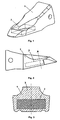
- a reinforced ground-engaging element of the invention as exemplified by a tooth (1), is shown to include a steel/cellular foam composite region (2).
- a side-elevation view of tooth (1) is illustrated and identifies a sectioning plane (A), which is orthogonal to the viewing direction and passes through the tooth (1) and through composite region (2).
- Figure 3 illustrates a sectional view of the tooth (1) in accordance with the sectional plane (A) that shows composite region (2) as surrounded by cast steel (3).
- the reinforced wearing element of the invention such as an excavator or loader tooth (1), includes a steel/cellular foam composite region (2).
- composite region (2) may have a simple rectangular box-shape within the tip portion of the tooth (1), it will be evident to one skilled in the art that other shapes and locations of composite region (2) can be adopted as suiting the expected in-service erosion development and wear pattern of the wearing element.
- composite region (2) may occupy only a certain portion of tooth (1), it is generally desirable that the size of composite region (2) be sufficiently extensive as to provide maximum wear resistance to the tooth (1) while minimizing the cost of the ceramic foam insert and the complexity of the cast-moulding arrangement.
- the insert included in the wearing element is a three-dimensional reticulated cellular ceramic foam with an open-celled porous structure that is substantially or completely penetrated by molten steel during gravity-casting of the element.
- the material of said insert is preferably a zirconia-based ceramic, such as, for example, zirconia-yttria, (ZrO 2 -Y 2 O 3 ), zirconia-magnesia (ZrO 2 -MgO), zirconia-calcia (ZrO 2 -CaO), or also a zirconia-alumina (ZrO 2 -Al 2 O 3 ) composite.
- the ceramic insert can otherwise be comprised by alumina-silicates (Al 2 O 3 -SiO 2 ) such as mullite, or high alumina (Al 2 O 3 ) materials such as, for example, white or tabular alumina, or aluminate materials such as, for example, aluminate spinel or zirconia-toughened alumina, or even ceramic carbides, such as silicon carbide (SiC). From the aforementioned materials, high alumina, aluminate and silicon carbide ceramics exhibit the highest hardness and may be thus expected to provide the highest wear resistance when properly infiltrated and bonded to a softer but tougher steel.
- alumina-silicates Al 2 O 3 -SiO 2
- Al 2 O 3 high alumina
- SiC silicon carbide
- alumina-based ceramics by liquid steel is comparatively and significantly poorer than that of the zirconia-based ceramics and it is also well known that silicon carbide can be easily dissolved by molten steel.
- coating of high alumina, aluminate and silicon carbide ceramic foams with a ceramic material of better wettability by molten steel, such as an alumina-silicate material, for example mullite, or a zirconia-based material facilitates infiltration and bonding.
- the so-coated ceramic foam can be formed by the immersion of poorly wettable ceramic foams into a slurry of the coating material followed by its firing.
- the cast steel is constituted by a low alloy steel that is readily hardened by normalizing, quenching and tempering heat treatment, having chemical analysis by weight percent; carbon content between 0.15% and 0.35%, silicon content between 0,5% and 2%, manganese content between 0.5% and 1.5%, chromium content between 0.5% and 2.5%, nickel content between 0% and 2%, molybdenum content between 0.15% and 0.35%, as well as small contents of aluminum and zirconium additions for deoxidation and residual levels of sulphur and phosphorus and other minor impurities or constituents.
- the silicon content of the cast steel is most influential in providing the liquid steel with fluidic properties at casting temperature that obtain the desired penetration of the ceramic foam inserts. In the context of obtaining a quality bonding between the cast steel and the ceramic foam insert, the preferred fluidic properties of the molten steel are obtained in steels having silicon contents greater than 1% by weight.
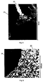
- Figure 4 is a micrograph of a polished sectional area within the steel/ceramic foam composite region (2) of an element of the invention.
- Infiltrated cast steel (21) of the aforementioned composition constitutes the dark features of the micrograph, while the lighter features comprise the walls of the ceramic foam (22), which in this instance is a zirconia-based ceramic material.
- the portion of the micrograph that shows a fine mixture of light and dark features is a portion where the infiltrated cast metal (21) has penetrated within the cell walls of the ceramic foam (22).
- a certain area (B) of the photomicrograph that includes a portion of fine penetration of the ceramic walls (22) by the infiltrated steel (21).
- Figure 5 is a high magnification micrograph of the certain area (B) in which there is a portion of fine penetration of the micro-porosity of the ceramic walls (22) by the infiltrated steel (21).
- the dark features are the infiltrated steel (21) and the light features comprise the walls of the ceramic foam (22).
- the dark portion toward the left-hand part of the micrograph is infiltrated steel (21) that is within what was once an open cell of the foam prior to infiltration, while the mottled portion toward the right-hand side of the micrograph is a fine intermix of light and dark features indicating fine penetration of the micro-porosity of the cell walls (22) by the infiltrated steel (21).
- Figure 4 and Figure 5 evidence the excellent interlocking of infiltrated steel (21) and the walls of the ceramic foam (22) that provides the quality bonding achieved within the steel/ceramic foam composite region (2) of an element of the invention.
- a particular feature in the present invention is that the steel infiltration of the ceramic foam insert, forming composite region (2), occurs both in the relatively large cells at macroscopic scale as well as in the cell walls at a micro-structural scale, so as to provide strong mechanical interlocking between the ceramic and the cast steel.
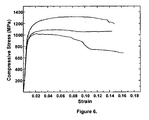
- the thusly-produced good bonding between metal and ceramic has been evidenced through uniaxial compressive testing of the steel-infiltrated foams (i.e., composite region (2)) after normalizing, quenching and tempering heat-treatment of the wearing element.
- the results show a rather elastic response to uniaxial stress levels up to the range of 700 MPa to 1000 MPa as determined with a strain offset of 0.01%.
- the elastic limit of the un-infiltrated cast steel (3) after normalizing, quenching and tempering heat-treatment of the wearing element has been determined to be in the range of 1400 to 1500 MPa.
- a minimum elastic limit of 700MPa provides a wide range of utility of the reinforced elements in ground-engaging applications, involving applied pressures as high as 1000 MPa, that include highly wear-resistant teeth for general purpose loaders and excavators.
- a further embodiment of the invention consists of a hybrid insert, i.e. a first ceramic foam insert as described before with a second insert that is introduced in said first insert so that said first insert is at least partially surrounding said second insert.
- Said second insert is preferably comprised by a cermet, most preferably made of cemented tungsten carbide, which is introduced inside a ceramic foam insert of the types described previously.
- a cermet insert provides an additional increase of wear resistance as compared to wearing elements reinforced only with the steel/ceramic composite region (2).
- the object of this embodiment is, as previously stated, a wearing element, i.e. a cast steel tooth, to be specially used in loading applications.
- the main purpose of the wearing element is the loading of loose mineral/stones into trucks, dumpers or any other transportation means in mining-sites, quarries or the like.
- the loading tooth of the present embodiment comprises a zirconia-based ceramic foam insert to improve the wear resistance of the tooth thus prolonging its service life.
- the reliability of the reinforced tooth is assured by obtaining quality bonding between the reinforcing ceramic foam insert and the cast steel constituting the tooth. Complete penetration of the cast steel within the cellular pores of the foam and within the microporosity of the cell walls has been achieved.
- the insert of the present embodiment is a sintered zirconia-based ceramic foam of 130 mm in length by 90 mm in width by 25 mm in height.
- the ceramic foam has been obtained by impregnating an open-celled polymeric foam with a slurry of the zirconia-based material and by subsequent firing.
- the so obtained ceramic foam is characterized by having an open cellular macroporosity of 20 ppi.
- the ceramic walls were microporous and contained some voids and cracks.
- the cast steel used to produce the wearing element of the present embodiment had a composition that comprised, by weight percent; 0.27% carbon, 1.5% silicon, 0.9% manganese; 2.1% chromium and 0.3% molybdenum.
- the wear element has been produced using no-bake resin-bonded silica-based sand moulding, commonly referred to as the ISOCURE Process.
- the mould was not preheated and had a ratio of sand to steel of 1,6 kg sand / kg of cast steel.
- the weight of steel poured in the mould to constitute the wearing element and to infiltrate the ceramic foam insert was 20.3 kg.
- Steel pouring temperatures in the range of 1550-1650°C were employed. These temperatures represent a superheating 50 to 150°C above the melting temperature of the low-alloy cast steel used to constitute the wearing element. In all cases, integrity of the ceramic foam has been preserved (i.e. no breaking due to thermal shock) and desired infiltration of the foam (macro- and micro- infiltration) has been achieved.
- the wearing elements were heat treated by a typical normalizing, quenching and low-temperature tempering practice, so as to obtain in the cast steel of the wearing element a microstructure consisting of mainly hard and tough tempered martensite.
- the reinforced wearing elements of this embodiment exhibited in-service an approximate 50% increase in life/duration as compared to unreinforced wearing elements of the same geometry, similar steel composition and similar heat-treatment.
Landscapes
- Engineering & Computer Science (AREA)
- Chemical & Material Sciences (AREA)
- Mechanical Engineering (AREA)
- Mining & Mineral Resources (AREA)
- Structural Engineering (AREA)
- Organic Chemistry (AREA)
- Materials Engineering (AREA)
- Ceramic Engineering (AREA)
- General Engineering & Computer Science (AREA)
- Civil Engineering (AREA)
- Geology (AREA)
- Metallurgy (AREA)
- Life Sciences & Earth Sciences (AREA)
- Geochemistry & Mineralogy (AREA)
- General Life Sciences & Earth Sciences (AREA)
- Inorganic Chemistry (AREA)
- Environmental & Geological Engineering (AREA)
- Physics & Mathematics (AREA)
- Fluid Mechanics (AREA)
- Manufacturing & Machinery (AREA)
- Porous Artificial Stone Or Porous Ceramic Products (AREA)
- Earth Drilling (AREA)
- Compositions Of Oxide Ceramics (AREA)
- Cutting Tools, Boring Holders, And Turrets (AREA)
- Component Parts Of Construction Machinery (AREA)
Claims (15)
- Verschleißelement für Maschinen zum Bewegen von Erde/Gestein, zum Eindringen in dem Boden und/oder zum Laden von Gestein, wie Schaufelzähne für Bagger und Lader, umfassend Gussstahl und mindestens einen Einsatz, dadurch gekennzeichnet, dass der genannte Einsatz ein zellenförmiger dreidimensionaler Keramikschaum ist, welcher eine poröse offenzellige Struktur aufweist, in welche der Gussstahl innerhalb der offenzelligen Porosität des Keramikschaumeinsatzes, sowie innerhalb der Mikroporosität der Keramikschaumwänden, durchdringt.
- Verschleißelement nach Anspruch 1, dadurch gekennzeichnet, dass der genannte Einsatz aus Zirconiumdioxid (ZrO2) oder aus einem auf Zirconiumdioxid basiertes Material, wie ZrO2-CaO, ZrO2-MgO, ZrO2-Y2O3, oder einem Verbund, wie ZrO2-Al2O3, hergestellt ist.
- Verschleißelement nach Anspruch 1, dadurch gekennzeichnet, dass der genannte Einsatz aus einem hochtonerdehaltigen Material, wie weißer Tonerde oder Tabulartonerde, oder aus einem Aluminatmaterial, wie Tonerdespinell oder mit Zirconiumdioxid verfestigter Tonerde, oder aus einem Tonerde-Silicat-Material (Al2O3-SiO2), wie Mullit, hergestellt ist.
- Verschleißelement nach Anspruch 1, dadurch gekennzeichnet, dass der genannte Einsatz aus einem beschichteten hochtonerdehaltigen Material (Al2O3), oder aus einem beschichteten Aluminatmaterial, wie Tonerdespinell oder mit Zirconiumdioxid verfestigtem Tonerdematerial, oder einem beschichteten Carbidmaterial, wie Siliciumcarbid, hergestellt ist, wobei die Beschichtung aus Tonerde-Silicat-Material oder auf Zirconiumdioxid basiertem Material gebildet ist.
- Verschleißelement nach einem der Ansprüche 1 bis 4, dadurch gekennzeichnet, dass die durchschnittliche Zellporosität des genannten Einsatzes zwischen 10 und 60 Poren pro Inch (ppi) liegt.
- Verschleißelement nach einem der Ansprüche 1 bis 5, dadurch gekennzeichnet, dass die durchschnittliche Zellporosität zwischen 20 und 30 ppi liegt.
- Verschleißelement nach einem der Ansprüche 1 bis 6, dadurch gekennzeichnet, dass der Volumenprozentsatz von Keramik des genannten Einsatzes aus zellenförmigem Schaum größer als 10% und kleiner als 35% ist, wobei der größte Teil des restlichen Volumens des Einsatzes durch den Gussstahl infiltriert wird.
- Verschleißelement nach einem der Ansprüche 1 bis 7, dadurch gekennzeichnet, dass der genannte Gussstahl eine Zusammensetzung aufweist, welche in Gewichtsprozent Kohlenstoff zwischen 0,15% und 0,35%, Silicium zwischen 0,5% und 2%, Mangan zwischen 0,5% und 1,5%, Chrom zwischen 0,5% und 2,5%, Nickel zwischen 0% und 2% und Molybdän zwischen 0,15% und 0,35% umfasst.
- Verschleißelement nach einem der Ansprüche 1 bis 8, dadurch gekennzeichnet, dass der genannte Gussstahl ein Siliciumgehalt in Gew.-% größer als 1% aufweist.
- Verschleißelement nach einem der Ansprüche 1 bis 9, dadurch gekennzeichnet, dass das genannte Element durch Normalglühung, Abschrecken und Tempern wärmebehandelt wird.
- Verschleißelement nach einem der Ansprüche 1 bis 10, dadurch gekennzeichnet, dass der Verbundbereich (2) aus Stahl/Keramikschaum, welcher in dem genannten Element gebildet ist, eine einachsige, elastische Druckspannungsgrenze größer als 700 MPa aufweist.
- Verschleißelement nach Anspruch 1, gekennzeichnet durch die Einfügung von mindestens einem zweiten Einsatz in, oder mindestens teilweise umgeben von, dem genannten ersten Einsatz.
- Verschleißelement nach Anspruch 12, wobei der genannte zweite Einsatz ein Wolframcarbidecermet ist.
- Verschleißelement nach einem der Ansprüche 1 bis 13, wobei das genannte Verschleißelement ein Zahn für Lade- oder Baggermaschinen ist.
- Verschleißelement nach einem der Ansprüche 1 bis 14, dadurch gekennzeichnet, dass die angewendeten Drücke auf der Verschleißfläche des in Betrieb gesetzten Verschleißelements 1000 MPa nicht überschreiten.
Priority Applications (2)
| Application Number | Priority Date | Filing Date | Title |
|---|---|---|---|
| EP10727670.1A EP2435636B1 (de) | 2009-05-29 | 2010-05-28 | Verschleissteil für bodeneingriffe mit erhöhter verschleissbeständigkeit |
| PL10727670T PL2435636T3 (pl) | 2009-05-29 | 2010-05-28 | Element zużywalny do prac ziemnych ze zwiększoną odpornością na zużycie |
Applications Claiming Priority (5)
| Application Number | Priority Date | Filing Date | Title |
|---|---|---|---|
| US21332109P | 2009-05-29 | 2009-05-29 | |
| PCT/ES2009/000352 WO2010136611A1 (es) | 2009-05-29 | 2009-07-01 | Elemento de desgaste con resistencia al desgaste mejorada |
| PCT/EP2009/005802 WO2010136055A1 (en) | 2009-05-29 | 2009-08-10 | Wear element for earth working machine with enhanced wear resistance |
| PCT/EP2010/003246 WO2010136208A1 (en) | 2009-05-29 | 2010-05-28 | Wearing element for ground engaging operations with enhanced wear resistance |
| EP10727670.1A EP2435636B1 (de) | 2009-05-29 | 2010-05-28 | Verschleissteil für bodeneingriffe mit erhöhter verschleissbeständigkeit |
Publications (2)
| Publication Number | Publication Date |
|---|---|
| EP2435636A1 EP2435636A1 (de) | 2012-04-04 |
| EP2435636B1 true EP2435636B1 (de) | 2014-04-02 |
Family
ID=46266934
Family Applications (1)
| Application Number | Title | Priority Date | Filing Date |
|---|---|---|---|
| EP10727670.1A Active EP2435636B1 (de) | 2009-05-29 | 2010-05-28 | Verschleissteil für bodeneingriffe mit erhöhter verschleissbeständigkeit |
Country Status (10)
| Country | Link |
|---|---|
| US (1) | US8763282B2 (de) |
| EP (1) | EP2435636B1 (de) |
| CN (1) | CN102482862B (de) |
| AU (1) | AU2010252229B2 (de) |
| CA (1) | CA2762933C (de) |
| ES (1) | ES2472917T3 (de) |
| PL (1) | PL2435636T3 (de) |
| RU (1) | RU2610934C9 (de) |
| WO (1) | WO2010136208A1 (de) |
| ZA (1) | ZA201108682B (de) |
Families Citing this family (67)
| Publication number | Priority date | Publication date | Assignee | Title |
|---|---|---|---|---|
| JP5716996B2 (ja) * | 2011-05-31 | 2015-05-13 | 新東工業株式会社 | 耐摩耗低合金鋳鋼 |
| CA2845723A1 (en) * | 2011-08-26 | 2013-03-07 | Volvo Construction Equipment Ab | Excavating tooth wear indicator and method |
| US8890672B2 (en) | 2011-08-29 | 2014-11-18 | Harnischfeger Technologies, Inc. | Metal tooth detection and locating |
| EP2828476B1 (de) * | 2012-03-22 | 2018-05-09 | Halliburton Energy Services, Inc. | Nanopartikelverstärkter bohrlochfilter |
| US9066462B2 (en) | 2012-05-03 | 2015-06-30 | Atom Jet Industries (2002) Ltd. | Working tools with wear resistant working surfaces for agricultural implements and other applications |
| CN103114245B (zh) * | 2013-02-03 | 2015-09-30 | 宁波华电铸钢有限公司 | 一种耐磨衬板及其制备方法 |
| CN104139172A (zh) * | 2013-05-08 | 2014-11-12 | 陈威 | 莫来石基陶瓷圆柱增强复合耐磨钢板成形方法 |
| US11199051B2 (en) | 2013-09-04 | 2021-12-14 | Schlumberger Technology Corporation | Cutting elements with wear resistant diamond surface |
| US10100583B2 (en) * | 2013-09-04 | 2018-10-16 | Smith International, Inc. | Cutting elements with wear resistant diamond surface |
| US9611625B2 (en) | 2015-05-22 | 2017-04-04 | Harnischfeger Technologies, Inc. | Industrial machine component detection and performance control |
| AU363298S (en) * | 2015-07-17 | 2015-08-11 | The State Of Queensland Through Its Dept Of Agriculture And Fisheries | Drill corer |
| USD774110S1 (en) * | 2015-08-12 | 2016-12-13 | Caterpillar Inc. | Tip for a ground engaging machine implement |
| USD774565S1 (en) | 2015-08-12 | 2016-12-20 | Caterpillar Inc. | Tip for a ground engaging machine implement |
| USD775673S1 (en) * | 2015-08-12 | 2017-01-03 | Caterpillar Inc. | Tip for a ground engaging machine implement |
| USD775240S1 (en) | 2015-08-12 | 2016-12-27 | Caterpillar Inc. | Tip for a ground engaging machine implement |
| USD774564S1 (en) | 2015-08-12 | 2016-12-20 | Caterpillar Inc. | Tip for a ground engaging machine implement |
| USD774567S1 (en) * | 2015-08-12 | 2016-12-20 | Caterpillar Inc. | Tip for a ground engaging machine implement |
| USD775242S1 (en) * | 2015-08-12 | 2016-12-27 | Caterpillar Inc. | Tip for a ground engaging machine implement |
| USD774109S1 (en) * | 2015-08-12 | 2016-12-13 | Caterpillar Inc. | Tip for a ground engaging machine implement |
| USD775243S1 (en) * | 2015-08-12 | 2016-12-27 | Caterpillar Inc. | Tip for a ground engaging machine implement |
| USD775241S1 (en) * | 2015-08-12 | 2016-12-27 | Caterpillar Inc. | Tip for a ground engaging machine implement |
| USD774566S1 (en) | 2015-08-12 | 2016-12-20 | Caterpillar Inc. | Tip for a ground engaging machine implement |
| USD774108S1 (en) * | 2015-08-12 | 2016-12-13 | Caterpillar Inc. | Tip for a ground engaging machine implement |
| AU2016354542B2 (en) | 2015-11-12 | 2019-03-07 | Joy Global Surface Mining Inc | Methods and systems for detecting heavy machine wear |
| JP6690991B2 (ja) | 2016-05-17 | 2020-04-28 | 株式会社小松製作所 | 耐摩耗部品およびその製造方法 |
| US10378188B2 (en) | 2016-09-23 | 2019-08-13 | Rockland Manufacturing Company | Bucket, blade, liner, or chute with visual wear indicator |
| KR102627470B1 (ko) * | 2016-11-17 | 2024-01-19 | 에이치디현대인프라코어 주식회사 | 건설 기계 버켓 부품 및 이의 제조 방법 |
| USD806759S1 (en) * | 2016-12-15 | 2018-01-02 | Caterpillar Inc. | Tip for a ground engaging machine implement |
| USD806140S1 (en) * | 2016-12-15 | 2017-12-26 | Caterpillar Inc. | Adapter for a ground engaging machine implement |
| USD803901S1 (en) * | 2016-12-15 | 2017-11-28 | Caterpillar Inc. | Tip for a ground engaging machine implement |
| USD805562S1 (en) * | 2016-12-15 | 2017-12-19 | Caterpillar Inc. | Adapter for a ground engaging machine implement |
| USD806139S1 (en) * | 2016-12-15 | 2017-12-26 | Caterpillar Inc. | Adapter for a ground engaging machine implement |
| USD803898S1 (en) * | 2016-12-15 | 2017-11-28 | Caterpillar Inc. | Tip for a ground engaging machine implement |
| USD803900S1 (en) * | 2016-12-15 | 2017-11-28 | Caterpillar Inc. | Tip for a ground engaging machine implement |
| USD803902S1 (en) * | 2016-12-15 | 2017-11-28 | Caterpillar Inc. | Tip for a ground engaging machine implement |
| USD806141S1 (en) * | 2016-12-15 | 2017-12-26 | Caterpillar Inc. | Adapter for a ground engaging machine implement |
| USD840441S1 (en) * | 2016-12-15 | 2019-02-12 | Caterpillar Inc. | Adapter for a ground engaging machine implement |
| USD805112S1 (en) * | 2016-12-15 | 2017-12-12 | Caterpillar Inc. | Tip for a ground engaging machine implement |
| USD803274S1 (en) * | 2016-12-15 | 2017-11-21 | Caterpillar Inc. | Tip for a ground engaging machine implement |
| USD806758S1 (en) * | 2016-12-15 | 2018-01-02 | Caterpillar Inc. | Tip for a ground engaging machine implement |
| USD803899S1 (en) * | 2016-12-15 | 2017-11-28 | Caterpillar Inc. | Tip for a ground engaging machine implement |
| USD803897S1 (en) * | 2016-12-15 | 2017-11-28 | Caterpillar Inc. | Tip for a ground engaging machine implement |
| US10184226B2 (en) | 2016-12-15 | 2019-01-22 | Caterpillar Inc. | Serrated cutting edge with ceramic insert |
| USD803275S1 (en) * | 2016-12-15 | 2017-11-21 | Caterpillar Inc. | Tip for a ground engaging machine implement |
| USD806142S1 (en) * | 2016-12-15 | 2017-12-26 | Caterpillar Inc. | Adapter for a ground engaging machine implement |
| US10323391B2 (en) | 2017-08-30 | 2019-06-18 | Caterpillar Inc. | Heavy duty shroud |
| USD832310S1 (en) | 2017-08-30 | 2018-10-30 | Caterpillar Inc. | Adapter for a ground engaging machine implement |
| US20190169822A1 (en) * | 2017-12-05 | 2019-06-06 | Esco Group Llc | Wear part and method of making the same |
| EP3563951A1 (de) * | 2018-05-04 | 2019-11-06 | Magotteaux International S.A. | Zahn aus verbundwerkstoff mit kegelstumpfförmigem einsatz |
| CN108941517B (zh) * | 2018-07-19 | 2021-09-17 | 柳州市创科复合金属陶瓷制品有限公司 | 一种炉口的制备方法 |
| USD888785S1 (en) | 2019-03-07 | 2020-06-30 | Caterpillar Inc. | Adapter for a ground engaging machine implement |
| USD905765S1 (en) | 2019-03-07 | 2020-12-22 | Caterpillar Inc. | Adapter for a ground engaging machine implement |
| USD894969S1 (en) | 2019-04-24 | 2020-09-01 | Caterpillar Inc. | Tip for a ground engaging machine implement |
| USD894968S1 (en) | 2019-04-24 | 2020-09-01 | Caterpillar Inc. | Adapter for a ground engaging machine implement |
| USD894970S1 (en) | 2019-04-24 | 2020-09-01 | Caterpillar Inc. | Adapter for a ground engaging machine implement |
| USD894972S1 (en) * | 2019-04-26 | 2020-09-01 | Caterpillar Inc. | Adapter for a ground engaging machine implement |
| USD894971S1 (en) * | 2019-04-26 | 2020-09-01 | Caterpillar Inc. | Tip for a ground engaging machine implement |
| USD897379S1 (en) * | 2019-04-26 | 2020-09-29 | Caterpillar Inc. | Tip for a ground engaging machine implement |
| EP3871807A1 (de) * | 2020-02-24 | 2021-09-01 | Parksen Group Pty Ltd | Verfahren zur gestaltung einer vorbereiteten harten oberfläche oder von harten punkten zum giessen eines produkts und entsprechendes giessen |
| AU2021251552B2 (en) | 2020-04-09 | 2024-02-08 | Komatsu Ltd. | Wear-resistant component |
| AU2021254246B2 (en) * | 2020-04-09 | 2024-02-08 | Komatsu Ltd. | Wear-resistant component |
| US11882777B2 (en) | 2020-07-21 | 2024-01-30 | Osmundson Mfg. Co. | Agricultural sweep with wear resistant coating |
| USD945499S1 (en) | 2020-11-18 | 2022-03-08 | Caterpillar Inc. | Adapter for a ground engaging machine implement |
| USD945498S1 (en) | 2020-11-18 | 2022-03-08 | Caterpillar Inc. | Adapter for a ground engaging machine implement |
| PE20240977A1 (es) * | 2020-12-04 | 2024-05-07 | Me Global Inc | Matriz de aleacion de fe para mineria resistente al desgaste y compuesto de ceramica de espinela |
| JP2024502902A (ja) * | 2020-12-10 | 2024-01-23 | マゴト・アンテルナシオナル・エス・アー | 構造上の強化材を備えた階層的複合摩耗部 |
| US20230332383A1 (en) * | 2022-04-13 | 2023-10-19 | Hensley Industries, Inc. | Reinforced wear member |
Family Cites Families (10)
| Publication number | Priority date | Publication date | Assignee | Title |
|---|---|---|---|---|
| US4547468A (en) | 1981-08-10 | 1985-10-15 | Terra Tek, Inc. | Hollow proppants and a process for their manufacture |
| JPS63101063A (ja) | 1986-10-16 | 1988-05-06 | Nabeya:Kk | 流体透過性製品及びその製造法 |
| JP2596106B2 (ja) * | 1988-12-27 | 1997-04-02 | 住友重機械鋳鍛株式会社 | 複合掘削ツース |
| GB9108297D0 (en) * | 1991-04-18 | 1991-06-05 | Gkn Sankey Ltd | Reinforced light metal article and method for its production |
| PT930948E (pt) | 1996-10-01 | 2001-01-31 | Magotteaux Int | Peca de desgaste composita |
| US20030213861A1 (en) * | 2002-05-15 | 2003-11-20 | Condon Gary J. | Crusher wear components |
| ITUD20030169A1 (it) | 2003-08-20 | 2005-02-21 | F A R Fonderie Acciaierie Roiale Spa | Procedimento per la produzione di un elemento soggetto ad usura, e elemento soggetto ad usura cosi' ottenuto. |
| CN2709630Y (zh) * | 2004-07-09 | 2005-07-13 | 方浩屹 | 牙轮钻头 |
| CN1785554A (zh) * | 2005-12-22 | 2006-06-14 | 河南科技大学 | 一种提高高锰钢耐磨件寿命的工艺 |
| US8056652B2 (en) * | 2007-06-25 | 2011-11-15 | Smith International, Inc. | Barrier coated granules for improved hardfacing material using atomic layer deposition |
-
2010
- 2010-05-28 EP EP10727670.1A patent/EP2435636B1/de active Active
- 2010-05-28 CN CN201080023481.8A patent/CN102482862B/zh not_active Expired - Fee Related
- 2010-05-28 PL PL10727670T patent/PL2435636T3/pl unknown
- 2010-05-28 RU RU2011147743A patent/RU2610934C9/ru active
- 2010-05-28 AU AU2010252229A patent/AU2010252229B2/en not_active Ceased
- 2010-05-28 CA CA2762933A patent/CA2762933C/en active Active
- 2010-05-28 US US13/322,881 patent/US8763282B2/en active Active
- 2010-05-28 ES ES10727670.1T patent/ES2472917T3/es active Active
- 2010-05-28 WO PCT/EP2010/003246 patent/WO2010136208A1/en not_active Ceased
-
2011
- 2011-11-25 ZA ZA2011/08682A patent/ZA201108682B/en unknown
Also Published As
| Publication number | Publication date |
|---|---|
| RU2011147743A (ru) | 2013-07-10 |
| AU2010252229A1 (en) | 2011-12-15 |
| AU2010252229B2 (en) | 2016-05-19 |
| US20120131821A1 (en) | 2012-05-31 |
| CA2762933A1 (en) | 2010-12-02 |
| CA2762933C (en) | 2017-01-17 |
| US8763282B2 (en) | 2014-07-01 |
| CN102482862B (zh) | 2015-03-18 |
| EP2435636A1 (de) | 2012-04-04 |
| ZA201108682B (en) | 2012-07-25 |
| CN102482862A (zh) | 2012-05-30 |
| PL2435636T3 (pl) | 2014-09-30 |
| RU2610934C9 (ru) | 2017-07-24 |
| WO2010136208A1 (en) | 2010-12-02 |
| RU2610934C2 (ru) | 2017-02-17 |
| ES2472917T3 (es) | 2014-07-03 |
Similar Documents
| Publication | Publication Date | Title |
|---|---|---|
| EP2435636B1 (de) | Verschleissteil für bodeneingriffe mit erhöhter verschleissbeständigkeit | |
| US5743033A (en) | Earthworking machine ground engaging tools having cast-in-place abrasion and impact resistant metal matrix composite components | |
| CN101275213B (zh) | 制造包括至少一个致密材料块体的元件的方法 | |
| CN102439233B (zh) | 具有强化的耐磨性的、用于土地/岩石工序的磨损元件 | |
| CN108472731B (zh) | 超硬构造及其制造方法 | |
| US5896911A (en) | Process for making a selectively reinforced ground engaging tool component | |
| KR102866200B1 (ko) | 복합 마모 부품 | |
| US5664616A (en) | Process for pressure infiltration casting and fusion bonding of a metal matrix composite component in a metallic article | |
| WO2010136055A1 (en) | Wear element for earth working machine with enhanced wear resistance | |
| US10364612B2 (en) | Roller cutting element construction | |
| Madej | Tungsten carbide as an addition to high speed steel based composites | |
| BRPI1009083B1 (pt) | Elemento de desgaste para máquinas para movimentar terra e rocha, penetrar no solo e/ou carregar a terra | |
| KR101935386B1 (ko) | 가압 함침용 강화재 예비성형체의 부유 방지 방법 및 부유 방지용 몰드 | |
| Berns et al. | Wear resistance of in situ MMC produced by supersolidus liquid phase sintering (SLPS) | |
| Iturriza-Zubillaga et al. | New strategies based on liquid phase sintering for manufacturing of diamond impregnated bits | |
| SE514167C2 (sv) | Metallmatris-kompositmaterial särskilt avsett för kolvringar | |
| Menapace et al. | PM Tool Materials: Microstructural and Mechanical Characterization of Iron and Copper Based Powders for Diamond Tools | |
| Besleaga et al. | New Types and Technologies for Scrapers Based on Materials Obtained Through PM | |
| WO2010136611A1 (es) | Elemento de desgaste con resistencia al desgaste mejorada |
Legal Events
| Date | Code | Title | Description |
|---|---|---|---|
| PUAI | Public reference made under article 153(3) epc to a published international application that has entered the european phase |
Free format text: ORIGINAL CODE: 0009012 |
|
| 17P | Request for examination filed |
Effective date: 20111219 |
|
| AK | Designated contracting states |
Kind code of ref document: A1 Designated state(s): AL AT BE BG CH CY CZ DE DK EE ES FI FR GB GR HR HU IE IS IT LI LT LU LV MC MK MT NL NO PL PT RO SE SI SK SM TR |
|
| DAX | Request for extension of the european patent (deleted) | ||
| 17Q | First examination report despatched |
Effective date: 20130419 |
|
| GRAP | Despatch of communication of intention to grant a patent |
Free format text: ORIGINAL CODE: EPIDOSNIGR1 |
|
| INTG | Intention to grant announced |
Effective date: 20140122 |
|
| GRAS | Grant fee paid |
Free format text: ORIGINAL CODE: EPIDOSNIGR3 |
|
| GRAA | (expected) grant |
Free format text: ORIGINAL CODE: 0009210 |
|
| AK | Designated contracting states |
Kind code of ref document: B1 Designated state(s): AL AT BE BG CH CY CZ DE DK EE ES FI FR GB GR HR HU IE IS IT LI LT LU LV MC MK MT NL NO PL PT RO SE SI SK SM TR |
|
| REG | Reference to a national code |
Ref country code: GB Ref legal event code: FG4D |
|
| REG | Reference to a national code |
Ref country code: AT Ref legal event code: REF Ref document number: 660253 Country of ref document: AT Kind code of ref document: T Effective date: 20140415 Ref country code: CH Ref legal event code: EP |
|
| REG | Reference to a national code |
Ref country code: IE Ref legal event code: FG4D |
|
| REG | Reference to a national code |
Ref country code: DE Ref legal event code: R096 Ref document number: 602010014811 Country of ref document: DE Effective date: 20140515 |
|
| REG | Reference to a national code |
Ref country code: ES Ref legal event code: FG2A Ref document number: 2472917 Country of ref document: ES Kind code of ref document: T3 Effective date: 20140703 |
|
| REG | Reference to a national code |
Ref country code: SE Ref legal event code: TRGR |
|
| REG | Reference to a national code |
Ref country code: NL Ref legal event code: T3 |
|
| REG | Reference to a national code |
Ref country code: AT Ref legal event code: MK05 Ref document number: 660253 Country of ref document: AT Kind code of ref document: T Effective date: 20140402 |
|
| REG | Reference to a national code |
Ref country code: NO Ref legal event code: T2 Effective date: 20140402 |
|
| REG | Reference to a national code |
Ref country code: LT Ref legal event code: MG4D |
|
| REG | Reference to a national code |
Ref country code: PL Ref legal event code: T3 |
|
| PG25 | Lapsed in a contracting state [announced via postgrant information from national office to epo] |
Ref country code: CY Free format text: LAPSE BECAUSE OF FAILURE TO SUBMIT A TRANSLATION OF THE DESCRIPTION OR TO PAY THE FEE WITHIN THE PRESCRIBED TIME-LIMIT Effective date: 20140402 Ref country code: CZ Free format text: LAPSE BECAUSE OF FAILURE TO SUBMIT A TRANSLATION OF THE DESCRIPTION OR TO PAY THE FEE WITHIN THE PRESCRIBED TIME-LIMIT Effective date: 20140402 Ref country code: BG Free format text: LAPSE BECAUSE OF FAILURE TO SUBMIT A TRANSLATION OF THE DESCRIPTION OR TO PAY THE FEE WITHIN THE PRESCRIBED TIME-LIMIT Effective date: 20140702 Ref country code: LT Free format text: LAPSE BECAUSE OF FAILURE TO SUBMIT A TRANSLATION OF THE DESCRIPTION OR TO PAY THE FEE WITHIN THE PRESCRIBED TIME-LIMIT Effective date: 20140402 Ref country code: IS Free format text: LAPSE BECAUSE OF FAILURE TO SUBMIT A TRANSLATION OF THE DESCRIPTION OR TO PAY THE FEE WITHIN THE PRESCRIBED TIME-LIMIT Effective date: 20140802 |
|
| PG25 | Lapsed in a contracting state [announced via postgrant information from national office to epo] |
Ref country code: LV Free format text: LAPSE BECAUSE OF FAILURE TO SUBMIT A TRANSLATION OF THE DESCRIPTION OR TO PAY THE FEE WITHIN THE PRESCRIBED TIME-LIMIT Effective date: 20140402 Ref country code: AT Free format text: LAPSE BECAUSE OF FAILURE TO SUBMIT A TRANSLATION OF THE DESCRIPTION OR TO PAY THE FEE WITHIN THE PRESCRIBED TIME-LIMIT Effective date: 20140402 Ref country code: HR Free format text: LAPSE BECAUSE OF FAILURE TO SUBMIT A TRANSLATION OF THE DESCRIPTION OR TO PAY THE FEE WITHIN THE PRESCRIBED TIME-LIMIT Effective date: 20140402 |
|
| PG25 | Lapsed in a contracting state [announced via postgrant information from national office to epo] |
Ref country code: PT Free format text: LAPSE BECAUSE OF FAILURE TO SUBMIT A TRANSLATION OF THE DESCRIPTION OR TO PAY THE FEE WITHIN THE PRESCRIBED TIME-LIMIT Effective date: 20140804 |
|
| REG | Reference to a national code |
Ref country code: CH Ref legal event code: PL |
|
| REG | Reference to a national code |
Ref country code: DE Ref legal event code: R097 Ref document number: 602010014811 Country of ref document: DE |
|
| PG25 | Lapsed in a contracting state [announced via postgrant information from national office to epo] |
Ref country code: CH Free format text: LAPSE BECAUSE OF NON-PAYMENT OF DUE FEES Effective date: 20140531 Ref country code: RO Free format text: LAPSE BECAUSE OF FAILURE TO SUBMIT A TRANSLATION OF THE DESCRIPTION OR TO PAY THE FEE WITHIN THE PRESCRIBED TIME-LIMIT Effective date: 20140402 Ref country code: SK Free format text: LAPSE BECAUSE OF FAILURE TO SUBMIT A TRANSLATION OF THE DESCRIPTION OR TO PAY THE FEE WITHIN THE PRESCRIBED TIME-LIMIT Effective date: 20140402 Ref country code: LI Free format text: LAPSE BECAUSE OF NON-PAYMENT OF DUE FEES Effective date: 20140531 Ref country code: DK Free format text: LAPSE BECAUSE OF FAILURE TO SUBMIT A TRANSLATION OF THE DESCRIPTION OR TO PAY THE FEE WITHIN THE PRESCRIBED TIME-LIMIT Effective date: 20140402 Ref country code: EE Free format text: LAPSE BECAUSE OF FAILURE TO SUBMIT A TRANSLATION OF THE DESCRIPTION OR TO PAY THE FEE WITHIN THE PRESCRIBED TIME-LIMIT Effective date: 20140402 Ref country code: MC Free format text: LAPSE BECAUSE OF FAILURE TO SUBMIT A TRANSLATION OF THE DESCRIPTION OR TO PAY THE FEE WITHIN THE PRESCRIBED TIME-LIMIT Effective date: 20140402 |
|
| PLBE | No opposition filed within time limit |
Free format text: ORIGINAL CODE: 0009261 |
|
| STAA | Information on the status of an ep patent application or granted ep patent |
Free format text: STATUS: NO OPPOSITION FILED WITHIN TIME LIMIT |
|
| REG | Reference to a national code |
Ref country code: IE Ref legal event code: MM4A |
|
| 26N | No opposition filed |
Effective date: 20150106 |
|
| REG | Reference to a national code |
Ref country code: DE Ref legal event code: R097 Ref document number: 602010014811 Country of ref document: DE Effective date: 20150106 |
|
| PG25 | Lapsed in a contracting state [announced via postgrant information from national office to epo] |
Ref country code: IE Free format text: LAPSE BECAUSE OF NON-PAYMENT OF DUE FEES Effective date: 20140528 |
|
| PG25 | Lapsed in a contracting state [announced via postgrant information from national office to epo] |
Ref country code: SI Free format text: LAPSE BECAUSE OF FAILURE TO SUBMIT A TRANSLATION OF THE DESCRIPTION OR TO PAY THE FEE WITHIN THE PRESCRIBED TIME-LIMIT Effective date: 20140402 |
|
| PG25 | Lapsed in a contracting state [announced via postgrant information from national office to epo] |
Ref country code: MT Free format text: LAPSE BECAUSE OF FAILURE TO SUBMIT A TRANSLATION OF THE DESCRIPTION OR TO PAY THE FEE WITHIN THE PRESCRIBED TIME-LIMIT Effective date: 20140402 |
|
| PG25 | Lapsed in a contracting state [announced via postgrant information from national office to epo] |
Ref country code: SM Free format text: LAPSE BECAUSE OF FAILURE TO SUBMIT A TRANSLATION OF THE DESCRIPTION OR TO PAY THE FEE WITHIN THE PRESCRIBED TIME-LIMIT Effective date: 20140402 |
|
| REG | Reference to a national code |
Ref country code: FR Ref legal event code: PLFP Year of fee payment: 7 |
|
| PG25 | Lapsed in a contracting state [announced via postgrant information from national office to epo] |
Ref country code: GR Free format text: LAPSE BECAUSE OF FAILURE TO SUBMIT A TRANSLATION OF THE DESCRIPTION OR TO PAY THE FEE WITHIN THE PRESCRIBED TIME-LIMIT Effective date: 20140402 |
|
| PG25 | Lapsed in a contracting state [announced via postgrant information from national office to epo] |
Ref country code: HU Free format text: LAPSE BECAUSE OF FAILURE TO SUBMIT A TRANSLATION OF THE DESCRIPTION OR TO PAY THE FEE WITHIN THE PRESCRIBED TIME-LIMIT; INVALID AB INITIO Effective date: 20100528 Ref country code: LU Free format text: LAPSE BECAUSE OF NON-PAYMENT OF DUE FEES Effective date: 20140528 |
|
| REG | Reference to a national code |
Ref country code: FR Ref legal event code: PLFP Year of fee payment: 8 |
|
| REG | Reference to a national code |
Ref country code: FR Ref legal event code: PLFP Year of fee payment: 9 |
|
| PG25 | Lapsed in a contracting state [announced via postgrant information from national office to epo] |
Ref country code: MK Free format text: LAPSE BECAUSE OF FAILURE TO SUBMIT A TRANSLATION OF THE DESCRIPTION OR TO PAY THE FEE WITHIN THE PRESCRIBED TIME-LIMIT Effective date: 20140402 |
|
| PG25 | Lapsed in a contracting state [announced via postgrant information from national office to epo] |
Ref country code: AL Free format text: LAPSE BECAUSE OF FAILURE TO SUBMIT A TRANSLATION OF THE DESCRIPTION OR TO PAY THE FEE WITHIN THE PRESCRIBED TIME-LIMIT Effective date: 20140402 |
|
| PGFP | Annual fee paid to national office [announced via postgrant information from national office to epo] |
Ref country code: NO Payment date: 20230530 Year of fee payment: 14 Ref country code: NL Payment date: 20230526 Year of fee payment: 14 Ref country code: IT Payment date: 20230519 Year of fee payment: 14 Ref country code: FR Payment date: 20230525 Year of fee payment: 14 Ref country code: ES Payment date: 20230601 Year of fee payment: 14 Ref country code: DE Payment date: 20230530 Year of fee payment: 14 |
|
| PGFP | Annual fee paid to national office [announced via postgrant information from national office to epo] |
Ref country code: TR Payment date: 20230511 Year of fee payment: 14 Ref country code: SE Payment date: 20230527 Year of fee payment: 14 Ref country code: PL Payment date: 20230508 Year of fee payment: 14 Ref country code: FI Payment date: 20230525 Year of fee payment: 14 |
|
| PGFP | Annual fee paid to national office [announced via postgrant information from national office to epo] |
Ref country code: BE Payment date: 20230529 Year of fee payment: 14 |
|
| PGFP | Annual fee paid to national office [announced via postgrant information from national office to epo] |
Ref country code: GB Payment date: 20230529 Year of fee payment: 14 |
|
| REG | Reference to a national code |
Ref country code: DE Ref legal event code: R119 Ref document number: 602010014811 Country of ref document: DE |
|
| REG | Reference to a national code |
Ref country code: SE Ref legal event code: EUG |
|
| REG | Reference to a national code |
Ref country code: NL Ref legal event code: MM Effective date: 20240601 |
|
| PG25 | Lapsed in a contracting state [announced via postgrant information from national office to epo] |
Ref country code: NO Free format text: LAPSE BECAUSE OF NON-PAYMENT OF DUE FEES Effective date: 20240531 |
|
| PG25 | Lapsed in a contracting state [announced via postgrant information from national office to epo] |
Ref country code: FI Free format text: LAPSE BECAUSE OF NON-PAYMENT OF DUE FEES Effective date: 20240528 |
|
| GBPC | Gb: european patent ceased through non-payment of renewal fee |
Effective date: 20240528 |
|
| PG25 | Lapsed in a contracting state [announced via postgrant information from national office to epo] |
Ref country code: NO Free format text: LAPSE BECAUSE OF NON-PAYMENT OF DUE FEES Effective date: 20240531 Ref country code: FI Free format text: LAPSE BECAUSE OF NON-PAYMENT OF DUE FEES Effective date: 20240528 |
|
| PG25 | Lapsed in a contracting state [announced via postgrant information from national office to epo] |
Ref country code: NL Free format text: LAPSE BECAUSE OF NON-PAYMENT OF DUE FEES Effective date: 20240601 |
|
| REG | Reference to a national code |
Ref country code: BE Ref legal event code: MM Effective date: 20240531 |
|
| PG25 | Lapsed in a contracting state [announced via postgrant information from national office to epo] |
Ref country code: DE Free format text: LAPSE BECAUSE OF NON-PAYMENT OF DUE FEES Effective date: 20241203 |
|
| PG25 | Lapsed in a contracting state [announced via postgrant information from national office to epo] |
Ref country code: BE Free format text: LAPSE BECAUSE OF NON-PAYMENT OF DUE FEES Effective date: 20240531 |
|
| PG25 | Lapsed in a contracting state [announced via postgrant information from national office to epo] |
Ref country code: FR Free format text: LAPSE BECAUSE OF NON-PAYMENT OF DUE FEES Effective date: 20240531 |
|
| PG25 | Lapsed in a contracting state [announced via postgrant information from national office to epo] |
Ref country code: IT Free format text: LAPSE BECAUSE OF NON-PAYMENT OF DUE FEES Effective date: 20240528 Ref country code: GB Free format text: LAPSE BECAUSE OF NON-PAYMENT OF DUE FEES Effective date: 20240528 |
|
| REG | Reference to a national code |
Ref country code: ES Ref legal event code: FD2A Effective date: 20250703 |
|
| PG25 | Lapsed in a contracting state [announced via postgrant information from national office to epo] |
Ref country code: ES Free format text: LAPSE BECAUSE OF NON-PAYMENT OF DUE FEES Effective date: 20240529 |
|
| PG25 | Lapsed in a contracting state [announced via postgrant information from national office to epo] |
Ref country code: SE Free format text: LAPSE BECAUSE OF NON-PAYMENT OF DUE FEES Effective date: 20240529 |
|
| PG25 | Lapsed in a contracting state [announced via postgrant information from national office to epo] |
Ref country code: PL Free format text: LAPSE BECAUSE OF NON-PAYMENT OF DUE FEES Effective date: 20240528 |