EP2434472A2 - Displaysystem für ein mobiles Messestandwandsystem - Google Patents
Displaysystem für ein mobiles Messestandwandsystem Download PDFInfo
- Publication number
- EP2434472A2 EP2434472A2 EP11181991A EP11181991A EP2434472A2 EP 2434472 A2 EP2434472 A2 EP 2434472A2 EP 11181991 A EP11181991 A EP 11181991A EP 11181991 A EP11181991 A EP 11181991A EP 2434472 A2 EP2434472 A2 EP 2434472A2
- Authority
- EP
- European Patent Office
- Prior art keywords
- display system
- shaft
- end pieces
- information carrier
- end piece
- Prior art date
- Legal status (The legal status is an assumption and is not a legal conclusion. Google has not performed a legal analysis and makes no representation as to the accuracy of the status listed.)
- Withdrawn
Links
- 239000004033 plastic Substances 0.000 claims description 6
- 229920003023 plastic Polymers 0.000 claims description 6
- 230000007246 mechanism Effects 0.000 claims description 4
- 229910052751 metal Inorganic materials 0.000 claims description 3
- 239000002184 metal Substances 0.000 claims description 3
- 238000004804 winding Methods 0.000 claims description 3
- 239000011152 fibreglass Substances 0.000 claims description 2
- 238000002347 injection Methods 0.000 claims description 2
- 239000007924 injection Substances 0.000 claims description 2
- 230000000881 depressing effect Effects 0.000 abstract 1
- 230000008901 benefit Effects 0.000 description 4
- 239000011093 chipboard Substances 0.000 description 4
- 239000003365 glass fiber Substances 0.000 description 3
- 238000004519 manufacturing process Methods 0.000 description 3
- 230000008859 change Effects 0.000 description 2
- 238000010276 construction Methods 0.000 description 2
- 238000003780 insertion Methods 0.000 description 2
- 230000037431 insertion Effects 0.000 description 2
- 238000009434 installation Methods 0.000 description 2
- 229910052782 aluminium Inorganic materials 0.000 description 1
- XAGFODPZIPBFFR-UHFFFAOYSA-N aluminium Chemical compound [Al] XAGFODPZIPBFFR-UHFFFAOYSA-N 0.000 description 1
- 239000000969 carrier Substances 0.000 description 1
- 230000000295 complement effect Effects 0.000 description 1
- 230000008878 coupling Effects 0.000 description 1
- 238000010168 coupling process Methods 0.000 description 1
- 238000005859 coupling reaction Methods 0.000 description 1
- 230000001419 dependent effect Effects 0.000 description 1
- 238000011161 development Methods 0.000 description 1
- 230000018109 developmental process Effects 0.000 description 1
- 238000001746 injection moulding Methods 0.000 description 1
- 239000000463 material Substances 0.000 description 1
- 230000001737 promoting effect Effects 0.000 description 1
- 239000007787 solid Substances 0.000 description 1
- 239000000243 solution Substances 0.000 description 1
- 229920001169 thermoplastic Polymers 0.000 description 1
- 229920001187 thermosetting polymer Polymers 0.000 description 1
- 239000004416 thermosoftening plastic Substances 0.000 description 1
Images
Classifications
-
- G—PHYSICS
- G09—EDUCATION; CRYPTOGRAPHY; DISPLAY; ADVERTISING; SEALS
- G09F—DISPLAYING; ADVERTISING; SIGNS; LABELS OR NAME-PLATES; SEALS
- G09F15/00—Boards, hoardings, pillars, or like structures for notices, placards, posters, or the like
- G09F15/0006—Boards, hoardings, pillars, or like structures for notices, placards, posters, or the like planar structures comprising one or more panels
- G09F15/0056—Boards, hoardings, pillars, or like structures for notices, placards, posters, or the like planar structures comprising one or more panels portable display standards
- G09F15/0062—Boards, hoardings, pillars, or like structures for notices, placards, posters, or the like planar structures comprising one or more panels portable display standards collapsible
-
- G—PHYSICS
- G09—EDUCATION; CRYPTOGRAPHY; DISPLAY; ADVERTISING; SEALS
- G09F—DISPLAYING; ADVERTISING; SIGNS; LABELS OR NAME-PLATES; SEALS
- G09F15/00—Boards, hoardings, pillars, or like structures for notices, placards, posters, or the like
- G09F15/0006—Boards, hoardings, pillars, or like structures for notices, placards, posters, or the like planar structures comprising one or more panels
- G09F15/0025—Boards, hoardings, pillars, or like structures for notices, placards, posters, or the like planar structures comprising one or more panels display surface tensioning means
-
- G—PHYSICS
- G09—EDUCATION; CRYPTOGRAPHY; DISPLAY; ADVERTISING; SEALS
- G09F—DISPLAYING; ADVERTISING; SIGNS; LABELS OR NAME-PLATES; SEALS
- G09F7/00—Signs, name or number plates, letters, numerals, or symbols; Panels or boards
- G09F7/18—Means for attaching signs, plates, panels, or boards to a supporting structure
-
- E—FIXED CONSTRUCTIONS
- E04—BUILDING
- E04H—BUILDINGS OR LIKE STRUCTURES FOR PARTICULAR PURPOSES; SWIMMING OR SPLASH BATHS OR POOLS; MASTS; FENCING; TENTS OR CANOPIES, IN GENERAL
- E04H1/00—Buildings or groups of buildings for dwelling or office purposes; General layout, e.g. modular co-ordination or staggered storeys
- E04H1/12—Small buildings or other erections for limited occupation, erected in the open air or arranged in buildings, e.g. kiosks, waiting shelters for bus stops or for filling stations, roofs for railway platforms, watchmen's huts or dressing cubicles
- E04H1/1272—Exhibition stands
-
- G—PHYSICS
- G09—EDUCATION; CRYPTOGRAPHY; DISPLAY; ADVERTISING; SEALS
- G09F—DISPLAYING; ADVERTISING; SIGNS; LABELS OR NAME-PLATES; SEALS
- G09F7/00—Signs, name or number plates, letters, numerals, or symbols; Panels or boards
- G09F7/18—Means for attaching signs, plates, panels, or boards to a supporting structure
- G09F2007/1804—Means for attaching signs, plates, panels, or boards to a supporting structure for fastening to a post
- G09F2007/1821—Means for attaching signs, plates, panels, or boards to a supporting structure for fastening to a post the post having slots or flanges to fasten the sign
-
- G—PHYSICS
- G09—EDUCATION; CRYPTOGRAPHY; DISPLAY; ADVERTISING; SEALS
- G09F—DISPLAYING; ADVERTISING; SIGNS; LABELS OR NAME-PLATES; SEALS
- G09F7/00—Signs, name or number plates, letters, numerals, or symbols; Panels or boards
- G09F7/18—Means for attaching signs, plates, panels, or boards to a supporting structure
- G09F2007/1834—Signs or the like supported by two lateral posts
-
- G—PHYSICS
- G09—EDUCATION; CRYPTOGRAPHY; DISPLAY; ADVERTISING; SEALS
- G09F—DISPLAYING; ADVERTISING; SIGNS; LABELS OR NAME-PLATES; SEALS
- G09F7/00—Signs, name or number plates, letters, numerals, or symbols; Panels or boards
- G09F7/18—Means for attaching signs, plates, panels, or boards to a supporting structure
- G09F2007/1873—Means for attaching signs, plates, panels, or boards to a supporting structure characterised by the type of sign
- G09F2007/1886—Tensioned flexible signs
-
- G—PHYSICS
- G09—EDUCATION; CRYPTOGRAPHY; DISPLAY; ADVERTISING; SEALS
- G09F—DISPLAYING; ADVERTISING; SIGNS; LABELS OR NAME-PLATES; SEALS
- G09F7/00—Signs, name or number plates, letters, numerals, or symbols; Panels or boards
- G09F7/18—Means for attaching signs, plates, panels, or boards to a supporting structure
- G09F2007/1873—Means for attaching signs, plates, panels, or boards to a supporting structure characterised by the type of sign
- G09F2007/1891—Means for attaching signs, plates, panels, or boards to a supporting structure characterised by the type of sign modular
Definitions
- Mobile exhibition wall systems usually consist of upright columns and the columns connecting the columns.
- the supports are not only kept at a distance, but also stabilized such that in an angled or over-corner arrangement of several of these elements, a further fixation is not necessary.
- the free space between the supports is filled, in particular with chipboard, which are printed or pasted in promotional manner.
- the supports are formed of extruded profiles, which have on each side of the support extending in the longitudinal direction of the support groove.
- the support may have four or in particular eight sides and a corresponding number of grooves.
- the frames are fixed by means of turnbuckles, which are arranged within the frames, which in turn are likewise formed from an extruded profile, and project axially from the end faces of the frames.
- the frame When setting up the exhibition stand, the frame is attached to the support in such a way that the turnbuckle engages in a groove of the support, and then turns on an externally accessible adjusting screw of the turnbuckle, so that it digs into the groove of the support.
- relatively bulky wall panels are inserted from micro-chipboard during the construction of the stand wall system, which serve as information carriers and advertising messages convey.
- the installation widths of such plates are between about 45 cm and 140 cm and the installation heights are usually about 250 cm.
- the handling during assembly and in particular the transport of these plates are expensive.
- the construction of the exhibition stand takes a correspondingly long time.
- measures must be taken to protect the graphics on these plates during transport and exhibition setup.
- it turns out to be disadvantageous that even a change of motif is relatively complicated, because the exhibition stand must be taken apart to replace such plates.
- Object of the present invention is therefore to propose a display system for a mobile exhibition stand wall system, which takes into account the aforementioned disadvantages and which is preferably fully compatible with the above-described exhibition stand wall systems.
- a display system comprises an elongated housing with a shaft accommodated therein for winding up a planar information carrier fixed thereto or to be fixed. At both end sides of the elongated housing, a separate end piece is provided in each case, which preferably has a receptacle for supporting the aforementioned shaft.
- the display system according to the invention is comparable to conventional shade systems, wherein the roller receiving the roller of the display system according to the invention preferably comprises a rotary shaft and a return spring, so that the flat information carrier automatically wound by means of the return spring shaft on the rotary shaft and accordingly disappears in the housing.
- the display system according to the invention corresponds to conventional roller blind systems.
- roller blind systems offer significant advantages over the chipboard solutions described above, especially during transport.
- the entire exhibition stand material can be transported by car, as bulky panels do not have to be transported.
- the graphics are perfectly protected during transport within the housing and can also be used for other applications.
- the display system according to the invention further provides that the end pieces of the elongated housing in which the shaft is mounted with the wound information carrier, each having a mounting plate, preferably from extend the end pieces in the radial direction beyond the elongate housing.
- These mounting plates each have at least one passage opening in the axial direction for the passage of at least one locking device for fixing the display system in the exhibition stand wall system.
- the display system according to the invention is thus not simply suspended from a frame of the exhibition stand wall system. Instead, it is connected directly to the exhibition stand wall system via its mounting plates.
- the display system forms in this way a bracing between the supports of the exhibition stand wall system and contributes to the stability of the booth wall system, which would otherwise lose stability in that chipboard is no longer used.
- the locking device for fixing the display system to the supports of the exhibition stand wall system preferably corresponds completely or at least substantially the locking devices with which otherwise the frames are connected to the supports.
- a corresponding Octanorm turnbuckle can be used in Octanorm standing wall systems.
- the elongated housing of the display system does not replace the actual frame of the booth wall system but is combined with the frame in a suitable manner.
- the actual frame is slightly shortened and inserted between the two mounting plates of the housing end caps, that it is adjacent to both sides of the mounting plates.
- the locking devices may advantageously be part of the frame in a conventional manner.
- they can be integrated in the interior of the frame in such a way that they protrude from the frame on the face side and through the passage opening of the mounting plate of the display system.
- the above-mentioned screws can be provided by means of which the locking devices can be brought into their locking position.
- the frame is accordingly formed in this preferred embodiment as a separate, detachable from the elongated housing element, instead of being welded to this, for example.
- the production cost and thus the cost of producing this display system is correspondingly low.
- the above-described preferred embodiment is on the one hand advantageous because it is system-compliant and the assembly is accordingly simple. On the other hand, it is precisely because of this system conformity that the setup time can be determined significantly reduce the booth, because the insertion of the frame and the attachment of the flat information carrier takes place in a common step. In addition, there are still the two other advantages that on the one hand the housing is fixed with the information carrier wound therein stable in the wall system and on the other hand contributes to the torsional rigidity of the wall system due to its coupling with the frame.
- the torsional rigidity of the exhibition stand wall system can be further increased if the end pieces of the housing have a flat axial outside, with which they rest against the pillars of the standing wall system.
- the flat axial outer side of the end pieces lies with the axial outer side of the mounting plate in a plane, which increase the contact surface with the adjoining support the stand wall system and thus the contribution to the torsional stiffness of the stand wall system accordingly.
- the elongated housing in which the flat information carrier is wound on the shaft, has an opening extending over the length of the housing, through which the information carrier emerges from the housing.
- this opening together with the frame forms a gap for the passage of the flat information carrier.
- This gap lies as centrally as possible below the shaft on which the information carrier is wound, so that the extended information carrier runs absolutely parallel to the supports of the exhibition stand wall system.
- the production of the display system is further simplified if the mounting plates each have an axial recess with a radial insertion opening, so that the frame in its fixation on the housing in simple manner in the radial direction in the recesses of the mounting plates can be inserted.
- the mounting plate is preferably formed integrally with the tail.
- the tail can be designed in particular as a flat plate, preferably made of metal.
- the end piece is produced as a plastic injection-molded part. Since the tail has a supporting function, not only for receiving the shaft on which the flat information carrier is wound, but especially for fixing the housing to the stand wall system, the plastic injection molded part must be made of a suitably hard and durable plastic. Particularly suitable for this example, glass fiber reinforced plastics, such as PA6 with glass fiber content. Plastic injection-molded end pieces can be formed almost arbitrarily and are therefore particularly suitable for the preferred embodiment of an end piece described in more detail below for the display system according to the invention.
- the end pieces are preferably formed as caps and have a concave inside and a convex outside.
- the concave inner side serves to receive an axial part of the shaft and of the flat information carrier wound thereon.
- the convex outer side has the function of reducing the width dimensions in the axial direction to the support of the exhibition stand system.
- each end piece has a centrally disposed planar surface coaxial with the extension direction of the mounting plate to provide a large bearing surface to the adjacent support of the standing wall system, and laterally to this flat surface an inclined surface has, for 90 ° arrangements of the display systems preferably has an inclination of about 45 °.
- the shaft on which the flat information carrier is wound preferably comprises a rotary shaft and a return spring shaft.
- At least one of the housing end pieces has for a receptacle for rotatably supporting the rotary shaft while the other end piece has a receptacle for non-rotatably supporting the return spring shaft.
- each end piece has a universal receptacle, which is designed both for rotatably supporting the rotary shaft and for non-rotatably supporting the return spring shaft. This makes it possible to produce only one type of end pieces, since it is suitable due to the universal receptacle for arrangement at each of the two ends of the planar information carrier receiving housing.
- a universal receptacle can be formed, for example, as a hole, in particular as a through hole, in the end piece and have a cross section which is composed of a polygonal, in particular rectangular, cross section and a circular cross section superimposed on the polygonal cross section.
- each tail an eccentrically to the axis of rotation arranged through hole through which a Vermosommesstatt can be inserted therethrough to block a winding of the flat information carrier when this first provided on one of the shaft Preliminary strips to be attached or exchanged for another flat information carrier.
- the display system according to the invention preferably also comprises a profile rail, in particular a U-profile rail, which can be attached to a free end of the information carrier to be fixed or fixed to the shaft.
- This profile rail has two functions. On the one hand, it prevents the running in of the free end of the flat information carrier in the housing of the display system.
- the profile rail in particular if it is designed as a U-profile rail, advantageously serve to mount the planar information carrier in the extended state on another frame of the wall system. The handling of the display system is very easy.
- the rail can be further advantageously equipped with a hook and loop mechanism.
- Velcro strips of a corresponding hook-and-loop fastener on the profile rail and corresponding hook strips can be provided on the free end of the flat information carrier, or vice versa.
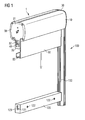
- FIG. 1 shows elements of a booth wall system 100, which is constructed essentially of vertical supports 110 and the supports interconnecting frames 120th Only part of the exhibition stand wall system 100, namely a support 110 and a frame, is reproduced here 120.
- the support 110 is formed as an extruded profile. In the illustrated embodiment, the outline of the extruded profile cross-section corresponds to a regular octagon.
- Each of the eight side surfaces of the support 110 thus formed has a groove 111 extending along the support 110. In this groove 111 engages a locking device 121, which is firmly integrated in the frame 120.
- the locking device 121 protrudes in an identical manner on both end faces 123 of the frame 120.
- a display system 1 is provided at the upper end of the support 110.
- the display system 1 has at its two end faces of the locking devices 121 of the frame 120 corresponding locking elements 41, with which it can be wedged in the grooves 111 of the support 110.
- the display system 1 consists essentially of a housing 10 in which a flat information carrier 50 is received, and two cap-shaped end pieces 30 at the two axial ends of the housing 10.
- the end pieces 30 have a planar axial outer side 31, with which they abut the supports 110.
- the end pieces 30 In the radial extension of the axial outer side, the end pieces 30 have a mounting plate 32 with a through opening 33, through which the locking elements 41 engages.
- the locking elements 41 are part of a in FIG. 1 not shown frame 20 (see FIG. 2 ) disposed between the mounting plates 32 adjacent thereto.
- a U-shaped rail 60 is fixed. By means of this rail 60th
- the information carrier 50 can be hooked under the lower frame 120 when it is pulled out of the housing 10 for display purposes.
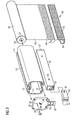
- FIG. 2 shows the individual components of the display system 1 in a perspective view.
- both the housing 10 and the frame 20 are designed as extruded profiles, in particular as aluminum extruded profiles.
- an end piece 30 is placed on one of the two axial end faces 11 of the housing 10 and screwed by means of four screws not shown here.
- the information carrier 50 is inserted from the opposite end face of the housing 10 axially into the housing 10 until an axially projecting cylindrical bearing pin 51 of a rotary shaft 52, on which the information carrier is wound, engages in a bearing hole 34 of the end piece 30.
- an end piece 30 is also placed on the opposite end face of the housing 10.
- a bearing pin with a rectangular cross section which belongs to a return spring shaft.
- the return spring shaft is rotatably mounted in a rectangular hole 35 of the end piece 30.
- the rectangular hole 35 and the bearing hole 34 are coaxially arranged in the end piece 30.
- an anti-rotation pin 70 is axially inserted through a through hole 36 in the end piece 30 into the rotation shaft 52 to secure the rotation shaft 52 against co-rotation.
- the return spring shaft can be biased by the patch on the opposite end face of the housing 10 end piece 30, in which the return spring shaft is rotatably mounted, as long as necessary about the axial axis of the elongate housing 10 is rotated.
- the cap is a Turned back rotation, so that the information carrier 50 or a leader strip to which an information carrier 50 is to be attached, protrudes from the lower elongated opening 13 of the housing 10 and is accessible.
- the other end cap 30 can be screwed to the housing 10.
- the rail 60 is mounted, which prevents entry of the information carrier 50 into the housing 10 and at the same time serves to lock the information carrier 50 in the extended state behind a frame 120 of the booth wall system 100.
- the information carrier 50 on its rear side on a first part 54 of a hook-and-loop fastener mechanism, and on the rail 60 of the complementary part 55 of the hook and loop mechanism is provided.
- an axial recess 37 is provided on the inside of the mounting plate 32, which is open at its radially outer end 38, so that the frame 20 from below into the recess 37 between the two end caps 30 can be inserted.
- the recess 37 with the radial opening 38 is in FIGS. 3b and 3c shown in more detail.
- the frame 20 is narrower than the elongated opening 12 of the housing 10, so that a gap remains through which the information carrier can enter and exit.
- a locking device 40 is introduced at both end faces 21 of the frame 20, the adjusting screw 42 through a passage opening of the frame 20 through a Torx finallyls, alternatively by means of an Allen key, can be operated. With appropriate operation of the adjusting screw 42, locking elements 41 of the locking device 40 can be moved axially through the passage opening 33 of the end piece 30 into the groove 111 of a support 110 and be wedged in the groove 111.
- the locking elements 41 are in the FIGS. 1 and 2 shown purely schematically or symbolically.
- the cross section of the support 110 is significantly narrower than the cross section of the housing 10 of the display system 1.
- the outer sides of the end pieces 30 are convex.
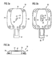
- an end piece 30 in the FIGS. 3a to 3c magnified reproduced.
- Figure 3c 3 clearly shows the convex outer side of the end piece 30 with a flat outer side 31 serving to abut the end piece 30 on the support 110 and on both sides adjacent thereto a respective inclined surface 39 which is inclined to the flat surface 31 by an angle of approximately 45 ° ° is inclined.
- FIG. 3a a plan view of the convex outer side of the end piece 30, shows FIG. 3b a rear view of the concave inside of the end piece 30.
- recesses 56 are introduced into the inner surface of the end piece 30. These recesses 56 serve to receive a portion of the wound in the housing 10 Information carrier 50. Since only a small portion of the wall of the end piece 30 is removed in the region of the recesses 56, this does not affect the overall stability of the tail 30 in any significant way. In particular, the recesses 56 do not penetrate to the outer surface of the end piece 30 and are therefore not visible.
- the complex structure of the end piece 30 can be produced particularly advantageously by injection molding.
- a high-strength plastic is used, in particular a thermoset or a crystalline, preferably glass fiber reinforced thermoplastic, such as PA6 with 30 wt .-% glass fiber content.
- the display system 1 is used with supports 110, the width of which is equal to or greater than the width of the display system 1 or if multiple display systems 1 are used only mutually aligned and not angled to each other, so instead of a concave-convex end piece 30 and a flat End piece, for example, consisting of a simple metal plate can be used.
- the display system 1 can be used both in place of a top frame, as in FIG. 1 shown, as used in place of the lower frame 120 in a booth wall system. In this case, the desired motif must be provided only upside down on the flat information carrier.
- a groove 12 is provided, can be fixed in the other system elements, such as special lighting means for illuminating the flat information carrier 50 from the front and / or from behind.
- a motif change with the display system 1 described above is very easy. It only takes the information carrier 50 so far to be pulled out of the housing 10 until the fixed to the shaft 52 leader strip is accessible. In this situation, first, the anti-rotation pin 70 is inserted through the through-hole 36 into the rotation shaft 52 to block retraction of the leader into the housing 10. Now it can be attached to the leader strip adhered information carrier 50 are exchanged for another information carrier. Finally, one pulls the anti-rotation pin 70 out of the through hole 36 again and leaves the information carrier 50 slowly and controlled back to the shaft 52.
Landscapes
- Physics & Mathematics (AREA)
- General Physics & Mathematics (AREA)
- Engineering & Computer Science (AREA)
- Theoretical Computer Science (AREA)
- Devices For Indicating Variable Information By Combining Individual Elements (AREA)
- Mirrors, Picture Frames, Photograph Stands, And Related Fastening Devices (AREA)
- Freezers Or Refrigerated Showcases (AREA)
Abstract
Description
- Mobile Messestandwandsysteme bestehen in der Regel aus aufrecht stehenden Stützen und die Stützen miteinander verbindenden Zargen. Durch die Zargen werden die Stützen nicht nur auf Abstand gehalten, sondern auch derart stabilisiert, dass bei einer winkligen oder Über-Eck-Anordnung mehrerer dieser Elemente eine weitere Fixierung nicht notwendig ist. Der freie Raum zwischen den Stützen wird gefüllt, insbesondere mit Spanplatten, die in werbewirksamer Weise bedruckt oder beklebt sind.
- Ein bekanntes Messestandwandsystem wird von der Firma Octanorm angeboten. Darin sind die Stützen aus Strangprofilen gebildet, die auf jeder Seite der Stütze eine in Stützenlängsrichtung verlaufende Nut aufweisen. Je nach Querschnitt der Stütze kann die Stütze vier oder insbesondere auch acht Seiten und eine entsprechende Anzahl von Nuten besitzen. In diesen Nuten werden die Zargen mittels Spannschlössern fixiert, die innerhalb der Zargen, welche ihrerseits ebenfalls aus einem Strangprofil gebildet sind, angeordnet sind und aus den Stirnseiten der Zargen axial hervorstehen. Beim Aufbau des Messestandes setzt man die Zarge so an die Stütze an, dass das Spannschloss in eine Nut der Stütze eingreift, und dreht dann an einer von außen zugänglichen Stellschraube des Spannschlosses, so dass sich dieses in der Nut der Stütze verkrallt. In dieselben Nuten der Stützen sowie in entsprechenden Nuten an der Ober- und Unterseite der Zargen werden während des Aufbaus des Standwandsystems relativ sperrige Wandfüllungen aus Mikrospanplatten eingeschoben, die als Informationsträger dienen und Werbebotschaften vermitteln. Die Einbaubreiten solcher Platten liegen zwischen etwa 45 cm und 140 cm und die Einbauhöhen betragen üblicherweise etwa 250 cm. Das Handling bei der Montage und insbesondere der Transport dieser Platten sind aufwendig. Der Aufbau des Messestandes braucht entsprechend lange. Darüber hinaus sind Maßnahmen zu treffen, um die Graphik auf diesen Platten während des Transports und des Messeaufbaus zu schützen. Schließlich stellt sich als nachteilhaft heraus, dass auch ein Motivwechsel relativ aufwendig ist, weil zum Austausch solcher Platten der Messestand auseinandergenommen werden muss.
- Aufgabe der vorliegenden Erfindung ist es daher, ein Displaysystem für ein mobiles Messestandwandsystem vorzuschlagen, welches den vorgenannten Nachteilen Rechnung trägt und welches vorzugsweise mit den vorbeschriebenen Messestandwandsystemen vollständig kompatibel ist.
- Diese Aufgabe wird durch ein Displaysystem mit den Merkmalen des Anspruchs 1 gelöst. In davon abhängigen Ansprüchen sind vorteilhafte Ausgestaltungen und Weiterbildungen der Erfindung angegeben.
- Dementsprechend umfasst ein erfindungsgemäßes Displaysystem ein längliches Gehäuse mit einer darin aufgenommenen Welle zum Aufwickeln eines daran fixierten oder zu fixierenden flächigen Informationsträgers. An beiden Stirnseiten des länglichen Gehäuses ist jeweils ein separates Endstück vorgesehen, welches vorzugsweise eine Aufnahme zum Lagern der vorgenannten Welle aufweist. Insoweit ist das erfindungsgemäße Displaysystem vergleichbar mit herkömmlichen Rollosystemen, wobei die das Rollo aufnehmende Welle des erfindungsgemäßen Displaysystems vorzugsweise eine Drehwelle und eine Rückholfederwelle umfasst, so dass sich der flächige Informationsträger mittels der Rückholfederwelle automatisch auf die Drehwelle aufwickelt und dementsprechend in dem Gehäuse verschwindet. Auch insoweit entspricht das erfindungsgemäße Displaysystem herkömmlichen Rollosystemen.
- Derartige Rollosysteme bieten gegenüber den vorbeschriebenen Spanplattenlösungen insbesondere beim Transport wesentliche Vorteile. So kann der Transport des gesamten Messestandmaterials gegebenenfalls mit einem Pkw erfolgen, weil sperrige Platten nicht transportiert werden müssen. Darüber hinaus bleibt die Graphik während des Transports innerhalb des Gehäuses perfekt geschützt und ist auch für weitere Einsätze einsetzbar.
- Um nun diese Vorteile in einem Messestandwandsystem der eingangs beschriebenen Art optimal ausnutzen zu können, sieht das erfindungsgemäße Displaysystem desweiteren vor, dass die Endstücke des länglichen Gehäuses, in denen die Welle mit dem aufgewickelten Informationsträger gelagert ist, jeweils eine Montageplatte aufweisen, die sich vorzugsweise von den Endstücken in radialer Richtung über das längliche Gehäuse hinaus erstrecken. Diese Montageplatten besitzen jeweils mindestens eine Durchgangsöffnung in axialer Richtung für den Durchtritt von mindestens einer Verriegelungseinrichtung zum Fixieren des Displaysystems in dem Messestandwandsystem.
- Das erfindungsgemäße Displaysystem wird somit nicht einfach an einer Zarge des Messestandwandsystems aufgehängt. Stattdessen wird es unmittelbar über seine Montageplatten mit dem Messestandwandsystem verbunden. Das Displaysystem bildet auf diese Weise eine Verstrebung zwischen den Stützen des Messestandwandsystems und trägt zur Stabilität des Messestandwandsystems bei, welches dadurch, dass Spanplatten nicht mehr verwendet werden, ansonsten an Stabilität verlieren würde. Die Verriegelungseinrichtung zum Fixieren des Displaysystems an den Stützen des Messestandwandsystems entspricht dabei vorzugsweise vollständig oder zumindest im wesentlichen den Verriegelungseinrichtungen, mit denen ansonsten die Zargen mit den Stützen verbunden werden. Insbesondere kann in Octanorm-Standwandsystemen ein entsprechendes Octanorm-Spannschloss zum Einsatz kommen.
- Gemäß einer bevorzugten Ausführungsform ersetzt das längliche Gehäuse des Displaysystems jedoch nicht die eigentliche Zarge des Messestandwandsystems sondern wird mit der Zarge in geeigneter Weise kombiniert. Dazu wird die eigentliche Zarge geringfügig gekürzt und derart zwischen die beiden Montageplatten der Gehäuseendkappen eingesetzt, dass sie beidseitig an die Montageplatten angrenzt. Bei dieser bevorzugten Variante können die Verriegelungseinrichtungen vorteilhaft in herkömmlicher Weise Teil der Zarge sein. Sie können insbesondere im Inneren der Zarge so integriert sein, dass sie stirnseitig aus der Zarge heraus und durch die Durchgangsöffnung der Montageplatte des Displaysystems hindurchragen. Bevorzugt können die eingangs bereits genannten Stellschrauben vorgesehen sein, mittels der die Verriegelungseinrichtungen in ihre Verriegelungsstellung bringbar sind.
- Die Zarge ist bei dieser bevorzugten Ausführungsform dementsprechend als separates, von dem länglichen Gehäuse lösbares Element ausgebildet, anstatt mit diesem beispielsweise verschweißt zu sein. Der Herstellungsaufwand und somit die Kosten zur Herstellung dieses Displaysystems ist dementsprechend gering.
- Die vorbeschriebene bevorzugte Ausführungsform ist einerseits vorteilhaft, weil sie systemkonform ist und die Montage dementsprechend einfach ist. Andererseits lässt sich gerade wegen dieser Systemkonformität die Aufstellzeit des Messestandes deutlich reduzieren, denn das Einsetzen der Zarge und das Anbringen des flächigen Informationsträgers erfolgt in einem gemeinsamen Schritt. Darüber hinaus ergeben sich noch die beiden weiteren Vorteile, dass einerseits das Gehäuse mit dem darin aufgewickelten Informationsträger stabil im Standwandsystem fixiert ist und andererseits aufgrund seiner Kopplung mit der Zarge zur Verwindungssteifigkeit des Standwandsystems beiträgt.
- Die Verwindungssteifigkeit des Messestandwandsystems kann noch weiter erhöht werden, wenn die Endstücke des Gehäuses eine flächige axiale Außenseite besitzen, mit der sie an den Stützen des Standwandsystems anliegen. Die flächige axiale Außenseite der Endstücke liegt dabei mit der axialen Außenseite der Montageplatte in einer Ebene, wodurch sich die Kontaktfläche mit der daran angrenzenden Stütze des Standwandsystems und somit der Beitrag zur Verwindungssteifigkeit des Standwandsystems entsprechend erhöhen.
- Das längliche Gehäuse, in welchem der flächige Informationsträger auf der Welle aufgewickelt ist, besitzt eine sich über die Länge des Gehäuses erstreckende Öffnung, durch die hindurch der Informationsträger aus dem Gehäuse austritt. Vorzugsweise bildet diese Öffnung zusammen mit der Zarge einen Spalt für den Durchtritt des flächigen Informationsträgers. Dieser Spalt liegt möglichst zentral unterhalb der Welle, auf der der Informationsträger aufgewickelt ist, so dass der ausgezogene Informationsträger absolut parallel zu den Stützen des Messestandwandsystems verläuft.
- Die Herstellung des Displaysystems wird weiter vereinfacht, wenn die Montageplatten jeweils eine axiale Ausnehmung mit einer radialen Einschuböffnung besitzen, so dass die Zarge bei ihrer Fixierung an dem Gehäuse in einfacher Weise in radialer Richtung in die Ausnehmungen der Montageplatten einschiebbar ist.
- Selbstverständlich ist die Montageplatte vorzugsweise einstückig mit dem Endstück ausgebildet. So kann das Endstück insbesondere als flache Platte, vorzugsweise aus Metall, ausgebildet sein. Besonders bevorzugt ist es aber, wenn das Endstück als Kunststoffspritzgussteil hergestellt wird. Da das Endstück tragende Funktion besitzt, nicht nur für die Aufnahme der Welle, auf der der flächige Informationsträger aufgewickelt ist, sondern vor allem zur Fixierung des Gehäuses an dem Standwandsystem, muss das Kunststoffspritzgussteil aus einem entsprechend harten und beständigen Kunststoff bestehen. Besonders geeignet sind hierfür beispielsweise glasfaserverstärkte Kunststoffe, wie etwa PA6 mit Glasfaseranteil. Aus Kunststoff spritzgegossene Endstücke können nahezu beliebig geformt sein und eignen sich daher besonders für die nachfolgend näher beschriebene bevorzugte Ausführungsform eines Endstücks für das erfindungsgemäße Displaysystem.
- Dementsprechend sind die Endstücke vorzugsweise als Kappen ausgebildet und weisen eine konkave Innenseite und eine konvexe Außenseite auf. Die konkave Innenseite dient dazu, einen axialen Teil der Welle und des darauf aufgewickelten flächigen Informationsträgers aufzunehmen. Die konvexe Außenseite hat dagegen die Funktion, die Breitenabmessungen in axialer Richtung zur Stütze des Messestandsystems hin zu reduzieren. Der besondere Vorteil dieser Endstückform liegt darin, dass damit ausgestattete Displaysysteme selbst dann über Eck oder winklig zueinander angeordnet werden können, wenn die Stützen des Standwandsystems schmaler sind als die Breite des Displaysystems. Ohne eine konvexe Außenseite des Endstücks würden zwei über Eck oder winklig zueinander angeordnete Displaysysteme an ihren aneinander angrenzenden Enden miteinander kollidieren, wenn sie an schmalen Stützen montiert werden sollen, und würden eine Montage dementsprechend vereiteln. Durch die Konvexität der Endstückaußenseiten wird diese Kollision vermieden, während gleichzeitig durch die Konkavität der Endstückinnenseite sichergestellt wird, dass ein möglichst breiter Informationsträger in dem Gehäuse Platz findet. Dadurch kann ein Spalt zwischen dem aus dem Gehäuse ausgezogenen flächigen Informationsträger und den Stützen des Standwandsystems minimal gehalten werden.
- Unter diesen Gesichtspunkten ist es besonders vorteilhaft, wenn die konvexe Außenseite eines jeden Endstücks eine zentral angeordnete ebene Fläche koaxial zur Erstreckungsrichtung der Montageplatte besitzt, um eine große Anlagefläche zu der angrenzenden Stütze des Standwandsystems zu bieten, und jeweils seitlich zu dieser ebenen Fläche eine geneigte Fläche besitzt, die für 90°-Anordnungen der Displaysysteme vorzugsweise eine Neigung von etwa 45° aufweist.
- Was die konkave Innenseite der Endstücke angeht, so ist es vorteilhaft, in der die Innenseite begrenzenden Wandung eines jeden Endstücks Ausnehmungen für den auf der Welle aufgenommenen flächigen Informationsträger vorzusehen. Dadurch kann die Breite des auf der Welle aufgewickelten flächigen Informationsträgers geringfügig vergrößert werden, so dass der zwischen dem ausgezogenen Informationsträger und den angrenzenden Stützen des Standwandsystems verbleibende Spalt entsprechend gering ist. Aufgrund von Symmetriebedingungen liegen diese Ausnehmungen in der die Innenseite begrenzenden Wandung - bezogen auf die Drehachse der Welle - einander gegenüber.
- Wie bereits erwähnt, umfasst die Welle, auf der der flächige Informationsträger aufgewickelt ist, vorzugsweise eine Drehwelle und eine Rückholfederwelle. Zumindest eines der Gehäuse-Endstücke besitzt dafür eine Aufnahme zum drehbaren Lagern der Drehwelle während das andere Endstück eine Aufnahme zum drehfesten Lagern der Rückholfederwelle aufweist. Besonders bevorzugt ist es aber, wenn jedes Endstück eine Universalaufnahme aufweist, die sowohl zum drehbaren Lagern der Drehwelle als auch zum drehfesten Lagern der Rückholfederwelle ausgebildet ist. Dies erlaubt es, nur eine Art von Endstücken zu produzieren, da sie aufgrund der Universalaufnahme zur Anordnung an jedem der beiden Enden des den flächigen Informationsträger aufnehmenden Gehäuses geeignet ist. Eine Universalaufnahme kann beispielsweise als Loch, insbesondere als Durchgangsloch, in dem Endstück ausgebildet sein und einen Querschnitt besitzen, der aus einem mehreckigen, insbesondere rechteckigen, Querschnitt und einem dem mehreckigen Querschnitt überlagerten Kreisquerschnitt zusammensetzt.
- Darüber hinaus weist zumindest eines der Endstücke, vorzugsweise aber aus herstellungstechnischen Gründen jedes Endstück, ein exzentrisch zur Drehachse angeordnetes Durchgangsloch auf, durch das ein Verdrehsicherungsstift hindurchgesteckt werden kann, um ein Aufwickeln des flächigen Informationsträgers zu blockieren, wenn dieser erstmals an einem an der Welle vorgesehenen Vorlaufstreifen angebracht oder gegen einen anderen flächigen Informationsträger ausgetauscht werden soll.
- Schließlich umfasst das erfindungsgemäße Displaysystem vorzugsweise noch eine Profilschiene, insbesondere eine U-Profilschiene, welche an einem freien Ende des an der Welle zu fixierenden oder fixierten Informationsträgers angebracht werden kann. Diese Profilschiene hat zwei Funktionen. Einerseits verhindert sie das Einlaufen des freien Endes des flächigen Informationsträgers in das Gehäuse des Displaysystems. Andererseits kann die Profilschiene, insbesondere wenn sie als U-Profilschiene ausgebildet ist, vorteilhaft dazu dienen, den flächigen Informationsträger im ausgezogenen Zustand an einer anderen Zarge des Standwandsystems einzuhängen. Die Handhabung des Displaysystems wird dadurch sehr einfach.
- Die Profilschiene kann weiter vorteilhaft mit einem Klettverschlussmechanismus ausgestattet sein. So können beispielsweise Flauschbänder eines entsprechenden Klettverschlusses an der Profilschiene und entsprechende Hakenbänder an dem freien Ende des flächigen Informationsträgers vorgesehen sein, oder umgekehrt.
- Nachfolgend wird die Erfindung anhand der anhängenden Zeichnungen beispielhaft erläutert. Darin zeigen:
- Figur 1
- ein Displaysystem im Zusammenwirken mit einer Stütze und einer Zarge eines mobilen Standwandsystems,
- Figur 2
- eine Explosionsansicht der Elemente des Displaysystems aus
Figur 1 in perspektivischer Ansicht, und - Figur 3a bis 3c
- ein kappenförmiges Endstück in zwei entgegengesetzten Aufsichten und einer Seitenansicht.
-
Figur 1 zeigt Elemente eines Messestandwandsystems 100, welches im wesentlichen aus senkrecht stehenden Stützen 110 und die Stützen miteinander verbindenden Zargen 120 aufgebaut ist. Wiedergegeben ist hier lediglich ein Teil des Messestandwandsystems 100, nämlich eine Stütze 110 und eine Zarge 120. Die Stütze 110 ist als Strangprofil ausgebildet. Im dargestellten Ausführungsbeispiel entspricht der Umriss des Strangprofilquerschnitts einem regelmäßigen Achteck. Jede der so gebildeten acht Seitenflächen der Stütze 110 weist eine sich entlang der Stütze 110 erstreckende Nut 111 auf. In diese Nut 111 greift eine Verriegelungseinrichtung 121 ein, die in der Zarge 120 fest integriert ist. Die Verriegelungseinrichtung 121 ragt in identischer Weise an beiden Stirnseiten 123 der Zarge 120 hervor. Durch Verdrehen einer Stellschraube 122 lässt sich jede Verriegelungseinrichtung 121, nachdem sie in eine Nut 111 der Stütze 110 eingesetzt worden ist, in der Nut 111 spreizen und verklemmen. - Anstelle einer weiteren Zarge 120 ist am oberen Ende der Stütze 110 ein Displaysystem 1 vorgesehen. Das Displaysystem 1 weist an seinen beiden Stirnseiten der Verriegelungseinrichtungen 121 der Zarge 120 entsprechende Verriegelungselemente 41 auf, mit denen es in den Nuten 111 der Stütze 110 verkeilt werden kann.
- Das Displaysystem 1 besteht im wesentlichen aus einem Gehäuse 10, in dem ein flächiger Informationsträger 50 aufgenommen ist, und aus zwei kappenförmigen Endstücken 30 an den beiden axialen Enden des Gehäuses 10. Die Endstücke 30 weisen eine ebene axiale Außenseite 31 auf, mit der sie an den Stützen 110 anliegen. In radialer Verlängerung der axialen Außenseite besitzen die Endstücke 30 eine Montageplatte 32 mit einer Durchgangsöffnung 33, durch die hindurch die Verriegelungselemente 41 greift. Die Verriegelungselemente 41 sind Teil einer in
Figur 1 nicht näher dargestellten Zarge 20 (sieheFigur 2 ), welche zwischen den Befestigungsplatten 32 angrenzend an diese angeordnet ist. Am unteren Ende des flächigen Informationsträgers 50 ist eine U-förmige Profilschiene 60 fixiert. Mittels dieser Profilschiene 60 kann der Informationsträger 50 unter die untere Zarge 120 eingehakt werden, wenn er zu Displayzwecken aus dem Gehäuse 10 herausgezogen wird. -
Figur 2 zeigt die einzelnen Bestandteile des Displaysystems 1 in perspektivischer Ansicht. Bei dem dargestellten Ausführungsbeispiel sind sowohl das Gehäuse 10 als auch die Zarge 20 als Strangprofile, insbesondere als Aluminiumstrangpressprofile, ausgeführt. Zunächst wird auf eine der beiden axialen Stirnseiten 11 des Gehäuses 10 ein Endstück 30 aufgesetzt und mittels vier hier nicht näher dargestellten Schrauben verschraubt. Anschließend wird der Informationsträger 50 von der gegenüberliegenden Stirnseite des Gehäuses 10 axial in das Gehäuse 10 eingeschoben, bis ein axial hervorstehender zylindrischer Lagerungsstift 51 einer Drehwelle 52, auf der der Informationsträger aufgewickelt ist, in ein Lagerungsloch 34 des Endstücks 30 eingreift. Daran anschließend wird auf die gegenüberliegende Stirnseite des Gehäuses 10 ebenfalls ein Endstück 30 aufgesetzt. Auf dieser gegenüberliegenden Stirnseite ragt anstelle des zylindrischen Lagerungsstifts 51 ein Lagerungsstift mit rechteckigem Querschnitt heraus, der zu einer Rückholfederwelle gehört. Mit diesem, nicht dargestellten rechteckigen Lagerungsstift wird die Rückholfederwelle drehfest in einem rechteckigen Loch 35 des Endstücks 30 gelagert. Das rechteckige Loch 35 und das Lagerungsloch 34 sind in dem Endstück 30 koaxial angeordnet. Bevor als nächstes die Rückholfederwelle vorgespannt wird, wird ein Verdrehsicherungsstift 70 axial durch ein Durchgangsloch 36 in dem Endstück 30 bis in die Drehwelle 52 eingeführt, um die Drehwelle 52 gegen ein Mitdrehen zu sichern. Nun kann die Rückholfederwelle vorgespannt werden, indem das auf der gegenüberliegenden Stirnseite des Gehäuses 10 aufgesetzte Endstück 30, in welchem die Rückholfederwelle drehfest gelagert ist, solange wie nötig um die axiale Achse des länglichen Gehäuses 10 gedreht wird. Nachdem die gewünschte Vorspannung der Rückholfederwelle erreicht ist, wird die Kappe um eine Umdrehung zurückgedreht, so dass der Informationsträger 50 oder ein Vorlaufstreifen, an dem ein Informationsträger 50 befestigt werden soll, aus der unteren länglichen Öffnung 13 des Gehäuse 10 herausragt und zugänglich ist. Nun kann auch die andere Endkappe 30 mit dem Gehäuse 10 verschraubt werden. - An dem freien Ende 53 des Informationsträgers 50 wird die Profilschiene 60 angebracht, die ein Einlaufen des Informationsträgers 50 in das Gehäuse 10 verhindert und gleichzeitig dazu dient, den Informationsträger 50 im ausgezogenen Zustand hinter einer Zarge 120 des Messestandwandsystems 100 zu verrasten. Dazu weist der Informationsträger 50 auf seiner Rückseite einen ersten Teil 54 eines Klettverschlussmechanismus auf, und an der Profilschiene 60 ist der dazu komplementäre Teil 55 des Klettverschlussmechanismus vorgesehen.
- Zwischen die Montageplatten 32 der Endstücke 30 wird zuletzt die Zarge 20 eingeschoben. Dazu ist auf der Innenseite der Montageplatte 32 eine axiale Aussparung 37 vorgesehen, die an ihrem radial äußeren Ende 38 offen ist, so dass die Zarge 20 von unten in die Aussparung 37 zwischen die beiden Endkappen 30 einschiebbar ist. Die Aussparung 37 mit der radialen Öffnung 38 ist in
Figuren 3b und 3c genauer dargestellt. Die Zarge 20 ist schmaler als die längliche Öffnung 12 des Gehäuses 10, so dass ein Spalt verbleibt, durch den hindurch der Informationsträger ein- und auslaufen kann. - Bevor jedoch die Zarge 20 zwischen die beiden Endstücke 30 eingeschoben wird, wird an beiden Stirnseiten 21 der Zarge 20 eine Verriegelungseinrichtung 40 eingeführt, deren Stellschraube 42 durch eine Durchgangsöffnung der Zarge 20 hindurch mittels eines Torxschlüssels, alternativ mittels eines Inbusschlüssels, bedienbar ist. Bei entsprechender Bedienung der Stellschraube 42 können Verriegelungselemente 41 der Verriegelungseinrichtung 40 axial durch die Durchgangsöffnung 33 des Endstücks 30 hindurch in die Nut 111 einer Stütze 110 hinein bewegt und in der Nut 111 verkeilt werden. Die Verriegelungselemente 41 sind in den
Figuren 1 und2 rein schematisch bzw. symbolisch dargestellt. - Der
Figur 1 ist zu entnehmen, dass der Querschnitt der Stütze 110 deutlich schmaler ist als der Querschnitt des Gehäuses 10 des Displaysystems 1. Um zu vermeiden, dass bei einer Über-Eck-Anordnung mehrerer Displaysysteme 1, insbesondere in einem 90°-Winkel, an ein und derselben Stütze 110 zur Kollision der Displaysysteme 1 führt, sind die Außenseiten der Endstücke 30 konvex ausgebildet. Zur Verdeutlichung dieser Maßnahme ist ein Endstück 30 in denFiguren 3a bis 3c vergrößert wiedergegeben. InsbesondereFigur 3c zeigt deutlich die konvexe Außenseite des Endstücks 30 mit einer ebenen Außenseite 31, die zur Anlage des Endstücks 30 an der Stütze 110 dient, und an beiden Seiten daran angrenzend eine jeweils geneigte Fläche 39, die zu der ebenen Fläche 31 um einen Winkel von etwa 45° geneigt ist. - Während
Figur 3a eine Draufsicht auf die konvexe Außenseite des Endstücks 30 zeigt, zeigtFigur 3b eine Rückansicht auf die konkave Innenseite des Endstücks 30. Zu beiden Seiten des Lagerungslochs 34 sind Ausnehmungen 56 in der inneren Oberfläche des Endstücks 30 eingebracht. Diese Ausnehmungen 56 dienen zur Aufnahme eines Teils des in dem Gehäuse 10 aufgewickelten Informationsträgers 50. Da nur ein geringfügiger Teil der Wandung des Endstücks 30 im Bereich der Ausnehmungen 56 entfernt ist, wirkt sich dies auf die Gesamtstabilität des Endstücks 30 nicht in nennenswerter Weise aus. Insbesondere dringen die Ausnehmungen 56 nicht bis an die äußere Oberfläche des Endstücks 30 hindurch und sind somit nicht sichtbar. - Die komplexe Struktur des Endstücks 30 lässt sich besonders günstig im Spritzgussverfahren herstellen. Aus Stabilitätsgründen wird ein hochfester Kunststoff verwendet, insbesondere ein Duroplast oder ein kristalliner, vorzugsweise glasfaserverstärkter Thermoplast, wie beispielsweise PA6 mit 30 Gew.-% Glasfaseranteil. Sofern das Displaysystem 1 jedoch mit Stützen 110 verwendet wird, deren Breite gleich oder größer ist als die Breite des Displaysystems 1 oder wenn mehrere Displaysysteme 1 nur zueinander fluchtend und nicht winklig zueinander eingesetzt werden, so kann anstelle eines konkav-konvexen Endstücks 30 auch ein ebenes Endstück, beispielsweise bestehend aus einer einfachen Metallplatte, verwendet werden.
- Das Displaysystem 1 kann sowohl anstelle einer oberen Zarge, wie in
Figur 1 gezeigt, als auch anstelle der unteren Zarge 120 in einem Messestandwandsystem eingesetzt werden. In diesem Falle muss das gewünschte Motiv lediglich auf dem Kopf stehend auf dem flächigen Informationsträger vorgesehen werden. - Zu erwähnen ist noch, dass auf der Oberseite des Gehäuses 10 eine Nut 12 vorgesehen ist, in der weitere Systemelemente fixiert werden können, wie beispielsweise besondere Beleuchtungsmittel zur Beleuchtung des flächigen Informationsträgers 50 von vorne und/oder von hinten.
- Letztlich bleibt noch anzumerken, dass ein Motivwechsel mit dem zuvor beschriebenen Displaysystem 1 sehr einfach möglich ist. Es braucht lediglich der Informationsträger 50 so weit aus dem Gehäuse 10 herausgezogen zu werden, bis der an der Welle 52 fixierte Vorlaufstreifen zugänglich ist. In dieser Situation wird zunächst der Verdrehsicherungsstift 70 durch das Durchgangsloch 36 in die Drehwelle 52 eingeführt, um ein Zurückziehen des Vorlaufstreifens in das Gehäuse 10 zu blockieren. Nun kann der an den Vorlaufstreifen angeklebte Informationsträger 50 gegen einen anderen Informationsträger ausgetauscht werden. Zuletzt zieht man den Verdrehsicherungsstift 70 wieder aus dem Durchgangsloch 36 heraus und lässt den Informationsträger 50 langsam und kontrolliert auf die Welle 52 zurücklaufen.
Claims (15)
- Displaysystem (1) für ein mobiles Messestandwandsystem (100), umfassend:- ein längliches Gehäuse (10) für eine darin aufgenommene Welle (52) zum Aufwickeln eines an der Welle (52) fixierten oder zu fixierenden flächigen Informationsträgers (50) und- an beiden Stirnseiten (11) des länglichen Gehäuses (10) jeweils ein separates Endstück (30), vorzugsweise mit einer Aufnahme (34, 35) zum Lagern der Welle (52),
dadurch gekennzeichnet, dass die Endstücke (30) jeweils eine Montageplatte (32) aufweisen, die sich vorzugsweise von den Endstücken (30) in radialer Richtung über das längliche Gehäuse (10) hinaus erstrecken und die jeweils mindestens eine Durchgangsöffnung (33) in axialer Richtung für den Durchtritt von mindestens einer Verriegelungseinrichtung (40) zum Fixieren des Displaysystems (1) in einem mobilen Messestandwandsystem (100) besitzen. - Displaysystem nach Anspruch 1, gekennzeichnet durch eine Zarge (20), welche sich zwischen den Montageplatten (32) der Endkappen (30) angrenzend an die Montageplatten (32) erstreckt und die Verriegelungseinrichtungen (40) trägt, wobei die Verriegelungseinrichtungen (40) vorzugsweise in der Zarge (20) montiert und weiter vorzugsweise mittels Stellschrauben (42) in eine Verriegelungsstellung bringbar sind.
- Displaysystem nach einem der Ansprüche 1 oder 2, dadurch gekennzeichnet, dass das längliche Gehäuse (10) eine sich über die Länge des Gehäuses erstreckende Öffnung (13) aufweist, die zusammen mit der Zarge (20) einen Spalt für den Durchtritt des flächigen Informationsträgers (50) bildet.
- Displaysystem nach einem der Ansprüche 1 bis 3, dadurch gekennzeichnet, dass die Montageplatten (32) jeweils eine axiale Ausnehmung (37) mit radialer Öffnung (38) besitzen und dass die Zarge (20) in radialer Richtung in die Ausnehmungen (37) der Montageplatten (32) einschiebbar ist.
- Displaysystem nach einem der Ansprüche 1 bis 4, dadurch gekennzeichnet, dass die Montageplatte (32) einstückig mit dem Endstück (30) ausgebildet ist.
- Displaysystem nach einem der Ansprüche 1 bis 5, dadurch gekennzeichnet, dass die Endstücke (30) jeweils eine ebene axiale Außenseite (31) besitzen.
- Displaysystem nach einem der Ansprüche 1 bis 6, dadurch gekennzeichnet, dass die Endstücke (30) als Kunststoffspritzgussteil hergestellt sind, welches vorzugsweise glasfaserverstärkten Kunststoff umfasst.
- Displaysystem nach einem der Ansprüche 1 bis 6, dadurch gekennzeichnet, dass die Endstücke (30) als flache Platten, vorzugsweise aus Metall, ausgebildet sind.
- Displaysystem nach einen der Ansprüche 1 bis 7, dadurch gekennzeichnet, dass die Endstücke (30) als Kappen mit einer konkaven Innenseite und einer konvexen Außenseite (31, 39) ausgebildet sind, wobei die konvexe Außenseite (31, 39) eines jeden Endstücks vorzugsweise eine zentral angeordnete ebene Fläche (31) koaxial zur Erstreckungsrichtung der Montageplatte (32) und jeweils seitlich zu dieser ebenen Fläche (31) eine geneigte Fläche (39), vorzugsweise mit etwa 45° Neigung, besitzt.
- Displaysystem nach Anspruch 9, dadurch gekennzeichnet, dass die konkave Innenseite eines jeden Endstücks (30) Ausnehmungen (56) in einer die Innenseite begrenzenden Wandung besitzt, wobei die Ausnehmungen (56) bezogen auf die Drehachse der Welle (52) einander gegenüber liegen.
- Displaysystem nach einem der Ansprüche 1 bis 10, dadurch gekennzeichnet, dass die Welle (52) eine Drehwelle und eine Rückholfederwelle umfasst, wobei zumindest eines der Endstücke (30) eine Aufnahme (34) zum drehbaren Lagern der Drehwelle und eines der Endstücke (30) eine Aufnahme (35) zum drehfesten Lagern der Rückholfederwelle aufweist.
- Displaysystem nach Anspruch 11, dadurch gekennzeichnet, dass jedes Endstück (30) eine Universalaufnahme (34, 35) aufweist, die sowohl zum drehbaren Lagern der Drehwelle als auch zum drehfesten Lagern der Rückholfederwelle ausgebildet ist, wobei die Universalaufnahme (34, 35) vorzugsweise als Loch in dem Endstück (30) ausgebildet ist, dessen Querschnitt sich aus einem mehreckigen Querschnitt und einem dem mehreckigen Querschnitt überlagerten Kreisquerschnitt zusammensetzt.
- Displaysystem nach einem der Ansprüche 11 oder 12, dadurch gekennzeichnet, dass zumindest eines der Endstücke (30), vorzugsweise jedes Endstück, ein exzentrisch zur Drehachse (34) der Welle (52) angeordnetes Durchgangsloch (36) zum Hindurchstecken eines Verdrehsicherungsstifts (70) aufweist.
- Displaysystem nach einem der Ansprüche 1 bis 13, gekennzeichnet durch zumindest eine Profilschiene (60) zum Anbringen an einem freien Ende eines an der Welle (52) zu fixierenden oder fixierten flächigen Informationsträgers (50), wobei die Profilschiene (60) zum Anbringen der Profilschiene (60) an einem an der Welle (52) zu fixierenden oder fixierten Informationsträger (50) vorzugsweise mit einem Klettverschlussmechanismus (55) ausgestattet ist.
- Messestandsystem (100), umfassend- zumindest zwei Stützen (110) mit Nuten (111),- zumindest zwei Zargen (120) zum Anordnen zwischen den Stützen (110),- Verriegelungseinrichtungen (121,122) zum Verbinden der Zargen (120) mit den Stützen (110), wobei die Verriegelungseinrichtungen (121, 122) von den Zargen (120) stirnseitig hervorstehen und in den Nuten (111) der Stützen (110) fixierbar sind, und- ein Displaysystem (1) nach einem der Ansprüche 1 bis 19, welches an den Stützen (110) dadurch fixierbar ist, dass Verriegelungselemente (40) des Displaysystems (1) durch die Durchgangsöffnungen (33) der Montageplatten (32) der Endstücke (30) des Displaysystems (1) hindurch in die Nuten (111) der Stützen (110) des Messestandsystems (100) eingreifen können.
Applications Claiming Priority (1)
| Application Number | Priority Date | Filing Date | Title |
|---|---|---|---|
| DE202010013547U DE202010013547U1 (de) | 2010-09-23 | 2010-09-23 | Displaysystem für ein mobiles Messestandwandsystem |
Publications (2)
| Publication Number | Publication Date |
|---|---|
| EP2434472A2 true EP2434472A2 (de) | 2012-03-28 |
| EP2434472A3 EP2434472A3 (de) | 2014-12-03 |
Family
ID=43536459
Family Applications (1)
| Application Number | Title | Priority Date | Filing Date |
|---|---|---|---|
| EP11181991.8A Withdrawn EP2434472A3 (de) | 2010-09-23 | 2011-09-20 | Displaysystem für ein mobiles Messestandwandsystem |
Country Status (2)
| Country | Link |
|---|---|
| EP (1) | EP2434472A3 (de) |
| DE (1) | DE202010013547U1 (de) |
Cited By (1)
| Publication number | Priority date | Publication date | Assignee | Title |
|---|---|---|---|---|
| CN114645589A (zh) * | 2022-03-31 | 2022-06-21 | 河北工程大学 | 一种装配式墙体用隔音边框及其装配式墙体构件 |
Family Cites Families (2)
| Publication number | Priority date | Publication date | Assignee | Title |
|---|---|---|---|---|
| DE202006018839U1 (de) * | 2006-12-04 | 2007-02-22 | Octanorm-Vertriebs-GmbH für Bauelemente | System zum Erstellen von Aufbauten und Tragprofil |
| CN101778990B (zh) * | 2007-01-03 | 2013-07-31 | 黄大智 | 一种电动遮阳系统 |
-
2010
- 2010-09-23 DE DE202010013547U patent/DE202010013547U1/de not_active Expired - Lifetime
-
2011
- 2011-09-20 EP EP11181991.8A patent/EP2434472A3/de not_active Withdrawn
Non-Patent Citations (1)
| Title |
|---|
| None |
Cited By (1)
| Publication number | Priority date | Publication date | Assignee | Title |
|---|---|---|---|---|
| CN114645589A (zh) * | 2022-03-31 | 2022-06-21 | 河北工程大学 | 一种装配式墙体用隔音边框及其装配式墙体构件 |
Also Published As
| Publication number | Publication date |
|---|---|
| EP2434472A3 (de) | 2014-12-03 |
| DE202010013547U1 (de) | 2011-02-03 |
Similar Documents
| Publication | Publication Date | Title |
|---|---|---|
| EP2066198B1 (de) | Präsentationsanordnung | |
| DE3934847C2 (de) | Transportable zerlegbare Kabine | |
| DE3341621A1 (de) | Schild mit zugehoerigem staender | |
| EP3175127B1 (de) | Eckverbinder für stabförmige profilelemente | |
| EP3613931B1 (de) | Baugruppe eines bandes zur um eine scharnierachse scharnierbeweglichen verbindung eines flügels an einem rahmen | |
| DE202012008665U1 (de) | Anordnung zum Befestigen eines Pfostens an einer Rahmenleiste eines Fensters oder einer Türe mittels eines Pfostenverbinders | |
| DE29601405U1 (de) | Verbindungsvorrichtung | |
| AT507225A1 (de) | Frühbeetverbindung | |
| CH657109A5 (de) | Traggestell. | |
| WO1985004220A1 (fr) | Element de liaison | |
| EP2434472A2 (de) | Displaysystem für ein mobiles Messestandwandsystem | |
| DE202008007378U1 (de) | Schraubclip | |
| EP2916687B1 (de) | Eckverbinder | |
| DE4126991A1 (de) | Stab mit einer verbindungsanordnung | |
| EP2524857B1 (de) | System mit Einzelmodulen zur Bildung eines Kofferaufbaus | |
| DE20102114U1 (de) | Kopfende mit abtrennbarem Zapfen besonders für Fliegengitter und so erhaltene Fliegengitterstruktur | |
| EP3406916B1 (de) | Winkelverbinder für tragprofile | |
| DE29603402U1 (de) | Rahmenwerk mit Winkel- oder Eckverbindungen von Metallprofilen, insbesondere aus Leichtmetall | |
| EP1085161B1 (de) | System zur Halterung von Einfach- oder Isolierglasplatten | |
| EP0833030B1 (de) | Band für Türen, Fenster und dergleichen | |
| DE202015100628U1 (de) | Blendrahmen für eine Tür oder ein Fenster | |
| DE202008006071U1 (de) | Leichtbauplatte zur Verwendung als Möbelplatte | |
| DE202007008397U1 (de) | Möbelsystem sowie Möbelstück | |
| DE3411041A1 (de) | Thekenaufsatz mit einem hebebeschlag zur schwenkbewegung einer scheibe um eine horizontale achse | |
| DE7919516U1 (de) | Verbindungsstueck fuer stellwaende |
Legal Events
| Date | Code | Title | Description |
|---|---|---|---|
| PUAI | Public reference made under article 153(3) epc to a published international application that has entered the european phase |
Free format text: ORIGINAL CODE: 0009012 |
|
| AK | Designated contracting states |
Kind code of ref document: A2 Designated state(s): AL AT BE BG CH CY CZ DE DK EE ES FI FR GB GR HR HU IE IS IT LI LT LU LV MC MK MT NL NO PL PT RO RS SE SI SK SM TR |
|
| AX | Request for extension of the european patent |
Extension state: BA ME |
|
| PUAL | Search report despatched |
Free format text: ORIGINAL CODE: 0009013 |
|
| AK | Designated contracting states |
Kind code of ref document: A3 Designated state(s): AL AT BE BG CH CY CZ DE DK EE ES FI FR GB GR HR HU IE IS IT LI LT LU LV MC MK MT NL NO PL PT RO RS SE SI SK SM TR |
|
| AX | Request for extension of the european patent |
Extension state: BA ME |
|
| RIC1 | Information provided on ipc code assigned before grant |
Ipc: G09F 15/00 20060101AFI20141024BHEP Ipc: E04H 1/12 20060101ALI20141024BHEP Ipc: G09F 7/18 20060101ALI20141024BHEP |
|
| STAA | Information on the status of an ep patent application or granted ep patent |
Free format text: STATUS: THE APPLICATION IS DEEMED TO BE WITHDRAWN |
|
| 18D | Application deemed to be withdrawn |
Effective date: 20150604 |