EP2434264B1 - Kraftübertragungsvorrichtung mit koppelbarem Kalibriergewicht - Google Patents
Kraftübertragungsvorrichtung mit koppelbarem Kalibriergewicht Download PDFInfo
- Publication number
- EP2434264B1 EP2434264B1 EP10179300.8A EP10179300A EP2434264B1 EP 2434264 B1 EP2434264 B1 EP 2434264B1 EP 10179300 A EP10179300 A EP 10179300A EP 2434264 B1 EP2434264 B1 EP 2434264B1
- Authority
- EP
- European Patent Office
- Prior art keywords
- parallel
- force
- calibration
- coupling means
- guided
- Prior art date
- Legal status (The legal status is an assumption and is not a legal conclusion. Google has not performed a legal analysis and makes no representation as to the accuracy of the status listed.)
- Active
Links
Images





Classifications
-
- G—PHYSICS
- G01—MEASURING; TESTING
- G01G—WEIGHING
- G01G21/00—Details of weighing apparatus
- G01G21/24—Guides or linkages for ensuring parallel motion of the weigh-pans
-
- G—PHYSICS
- G01—MEASURING; TESTING
- G01G—WEIGHING
- G01G23/00—Auxiliary devices for weighing apparatus
- G01G23/01—Testing or calibrating of weighing apparatus
- G01G23/012—Testing or calibrating of weighing apparatus with load cells comprising in-build calibration weights
-
- G—PHYSICS
- G01—MEASURING; TESTING
- G01G—WEIGHING
- G01G7/00—Weighing apparatus wherein the balancing is effected by magnetic, electromagnetic, or electrostatic action, or by means not provided for in the preceding groups
- G01G7/02—Weighing apparatus wherein the balancing is effected by magnetic, electromagnetic, or electrostatic action, or by means not provided for in the preceding groups by electromagnetic action
Definitions
- the present invention relates to a power transmission device for a gravimetric measuring instrument, wherein the power transmission device has a load receiving area and a fixed area.
- a weighing pan connected to the load receiving area receives the load to be weighed, the force of which on the weighing pan is transmitted directly or by means of a power-reducing lever mechanism to a measuring sensor.
- a parallelogram guide for vertical guidance of the weighing pan and the load receiving area, the power transmission device and the sensor essentially form a load cell of a gravimetric measuring instrument.
- load cells with strain gauges
- load cells with string or EMFC load cells Electro Magnetic Force Compensation
- Gravimetric measuring instruments with string or EMFC load cells deliver measurement results with a very high resolution.
- the weight of the load is transmitted either directly or through one or more power transmission levers in an electromechanical sensor, which emits an electrical signal corresponding to the weight of the weighing load, which is further processed by a weighing electronics and displayed.
- string load cells In the case of string load cells, the mechanical design largely corresponds to the EMFC load cells, with the difference that instead of an electromagnetic transducer a vibrating string transducer is used.
- the load tightens a vibrating string whose frequency change is a measure of the applied load.
- the mechanical system of the EMFC load cells in the equilibrium position is similar to a mechanical beam balance with counterweights at the time of the measurement acquisition, the load receiving area of a string load cell has a small vertical displacement to the fixed area since the string is tensioned under load and stretch slightly. Therefore, string load cells are also referred to as "low-inertia load cells".
- Both types of weighing cells are used, for example, in precision scales and analytical scales in the milligram range or in micrograms in the microgram range and require periodic calibration so that they provide measured values within a prescribed tolerance range in accordance with the manufacturer's instructions and legal requirements. With these periodic calibrations, influences acting on the load cell are corrected, for example, a changing ambient temperature or the changing air pressure.
- the calibration is carried out by periodically loading the load receiving area with a known weight. From the difference between the value determined prior to delivery of the load cell at the final check and the currently measured value, a correction value can be calculated by means of which the subsequent measurement results of the load cell can be corrected. To obtain the most accurate calibration value possible, the calibration weight should correspond to the maximum permissible load of the load cell. This may mean that very large calibration weights are required.
- Such a working according to the principle of electromagnetic force compensation gravimetric measuring instrument with built, rod-shaped calibration weight is in the EP 0 955 530 B1 disclosed.
- the rod-shaped calibration weight is placed on a coupled with the load receiving range Kalibrierwhosarm, which serves as a translation lever. Thanks to this translation, the mass of the calibration weight and thus its dimensions can be kept small.
- the calibration weight arm is always coupled to the load receiving area, it merely serves as a translation and record for the calibration weight during the calibration process and is not part of the calibration weight itself.
- the calibration weight arm is thus part of a power transmission device or a lever mechanism for transmitting and reducing the load on the sensor and is also connected during the weighing operation with the load receiving area.
- the power transmission device may also comprise a multi-stage lever mechanism, wherein the individual levers are connected by means of coupling elements in a suitable manner, so that between the load receiving area and the sensor, a force reduction is achieved.
- suitable receptacles for placing a calibration weight are formed on one of the coupling elements.
- the JP 3761792 B2 discloses a load cell equipped with strain gauges, which has a calibration weight with a transmission lever. Between the transmission lever and the load receiving area, a coupling element is arranged. By raising the calibration weight and the coupling element, a bearing cup formed on the coupling element is lifted by a cutting bearing arranged on the load receiving area, thereby decoupling the transmission lever from the load receiving area.
- the precise determination of the correction value depends not only on the resolution of the sensor, but also substantially on the precise compliance with the geometric conditions. Even the smallest deviations of the applied calibration weight from its nominal position to z. B in the EP 0 955 530 B1 Kalibrierwhisarm described in the CH 661 121 A5 described coupling link or slight displacements of the position of the pan to the cutting bearing in the JP3761792 B2 lead to an extension or shortening of the effective lever arm and thus to a faulty correction value. As a result, the points of contact between the calibration weight and Kalibrieritessarm or cutting bearing and pan are manufactured with the greatest precision and at high cost.
- the object of the present invention is to provide a force transmission device for a gravimetric measuring instrument with a measuring sensor, with which a calibration weight can be brought into abutment in such a way that the influence of changing geometric conditions on the calibrating weight force acting on the sensor is minimized.
- a power transmission device of a gravimetric measuring instrument has a fixed portion and a load receiving portion.
- the load receiving area is directly or at least connected by at least one coupling element and at least one lever force-transmitting with a arranged on the fixed area sensor.
- the force transmission device according to the invention has a parallel-guided coupling means and a calibration lever whose articulation point is supported on the fixed area.
- the calibration lever includes a first and a second calibration lever arm, wherein between the second calibration lever of the calibration lever and the at least one coupling element or a lever arm of the at least one lever, the parallel-guided coupling means is arranged.
- the parallel-guided coupling means is divided in two into a fixed partial coupling means and into a parallel-guided partial coupling means, which are aligned with one another such that only a compressive or tensile force can be transmitted between them.
- the parallel-guided partial coupling means comprises a first and a second parallel element which are arranged parallel to one another and via which the parallel-guided partial coupling means is fixed either on the second calibration arm or on the load receiving area, on the coupling element or on the lever arm, so that relative transverse movements occurring during the power transmission by the parallel-guided coupling means be compensated by the first and second parallel element.
- the calibration weight can thus be coupled by means of the parallel-guided coupling means in the power transmission device, so that it can be calibrated.
- the calibration weight can due to different pivoting radii between the coupling point of the calibration and the Distance to the nearest bearing points transverse displacements occur, which can be compensated in particular by the parallel-guided coupling means and more precisely the parallel-guided partial coupling means.
- the parallel-guided coupling means is designed such that only compressive or tensile forces in the direction of the central longitudinal axis of the parallel-guided coupling means can be transmitted between the fixed and the parallel-guided partial coupling means.
- the two-part design of the parallel-guided coupling means makes it possible to couple the calibration lever and the calibration weight firmly connected to this with the load receiving area, a coupling element or a lever arm of the power transmission device or completely decoupled.
- the coupling or decoupling operation can be carried out by raising or lowering the calibration weight by means of the above-mentioned calibration weight applying device.
- the parallel-guided coupling means thus serves in particular for transmitting the calibration weight by tension or pressure. When loaded in the opposite direction, the two sub-coupling means separate from each other, whereby no power transmission between them is possible.
- this release can also apply only to a certain displacement distance of a sub-coupling means relative to the other sub-coupling means, in the sense of the invention, only this particular displacement distance is considered.
- the two sub-coupling means do not touch and thus no force can be transmitted between the two sub-coupling means.
- the two parallel elements of the parallel-guided partial coupling means are designed such that on the one hand as flexible as possible and thereby causing their bending low bending moments and on the other hand designed stable enough that their lability does not cause the sub-coupling means due to gravity or by inertial and acceleration forces during operation of the power transmission device deflect.
- the two parallel elements are aligned parallel to one another and to the direction of the force which can be transmitted by the parallel-guided coupling means.
- the two parallel elements are used, even low relative transverse displacements in the coupling of the calibration compensate, which can occur during the transmission of power or the determination of the calibration measured value.
- the power transmission does not take place via the support points of the calibration weight, but via the parallel-guided coupling means or via its parallel elements. Consequently, the geometric relationships always remain the same, since smallest displacements, in particular relative transverse displacements between the fixed and the parallel-guided partial coupling means are compensated by the parallel-guided partial coupling means and do not take place in the actual force introduction points, which are defined by the immutable position of the two partial coupling means and the two parallel elements , Since with load cells with electromagnetic force compensation the measurement values are recorded in the balanced state, the bending moments in the bearing points of the power transmission device are approximately zero.
- the calibration lever or its articulation point is preferably designed accordingly, so that the pivot bearing is free of bending moment during the calibration process.
- the fixed partial coupling means and the parallel-guided partial coupling means for transmitting compressive forces in each case at least one point of contact, which are aligned with each other.
- the contact points for power transmission can be designed so that the fixed and the parallel-guided partial coupling means are centered to each other during the calibration process.
- one of the two partial coupling means may have a first pulling element, eg with a projection
- the other partial coupling means may have a second pulling element, eg with a socket, wherein the first pulling element and the second pulling element interlock, the projection is aligned with the socket is and transfer of tensile forces the projection with the pan in plant.
- the first tension element can be arranged at least partially within the partial coupling element having the second tension element.
- the first traction element can thus be arranged at least partially within the sub-coupling means, which has the second traction element or engages in this.
- the first and the second parallel element have thin-layer bending bearings which, due to their generic properties, in particular the pressure or tensile force transmission along their central longitudinal axis, their spring action and their bending properties, are particularly suitable for use in a parallel-guided coupling means according to the invention.
- the power transmission device may also include a parallel guide, so that is guided in the operating position of the load receiving area by means of at least one upper parallel link and by means of at least one lower parallel link at the fixed area in the vertical direction.
- the power transmission device may consist of various individual parts, which are joined together by means of connecting elements to form a unit. However, several of these parts can also be connected to one another in a material-locking manner. Preferably, at least the load receiving area, the fixed area, the calibration lever and the parallel-guided coupling means are monolithically connected to each other.
- the inventive Power transmission device can be used together with a sensor and with a calibration weight as a load cell in a gravimetric measuring instrument.
- a gravimetric measuring instrument is usually calibrated in such a way that the weight of the calibration weight can be transmitted to the sensor by the force transmission device in the same direction as a force acting on the load receiving area. Consequently, the sensor is loaded in the same way with a calibration force as in normal operation with a load to be weighed.
- the sensor can usually only be loaded in the load direction, which is why the embodiment described above is suitable for string and EMFC load cells.
- the weight of the calibration by the power transmission device in the opposite direction as a force acting on the load receiving force on the sensor is transferable.
- This version is particularly suitable for EMFC load cells, which have a sensor with push-pull system, as in the US 20080218303 A1 is described in detail. Due to this configuration, the calibration can be used as a compensation weight to increase the load range of the load cell. For example, with a decoupled calibration weight, a load cell formed in this way could weigh loads in the range of 0-100 grams and expand the weighing range with coupled calibration weight and weigh loads in the range of 100-200 grams, since the weight force of the calibration weight counteracts the load acting on the load receiving area.
- the calibration weight can also be partially made of the same material as the power transmission device and be provided with a supplementary mass higher density.
- a pressure sensor for detecting the ambient pressure of the gravimetric measuring instrument may also be present. Its measured value can be used to correct the buoyancy of the calibration weight, since the buoyancy force of the air displaced by the calibration weight counteracts the weight of the calibration weight.
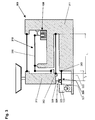
- FIG. 1 shows in plan view a schematic representation of a load cell 100 with an embodiment of the power transmission device 110.
- the Power transmission device 110 has a fixed portion 111 and a load receiving portion 112.
- the load receiving area 112 is fixed by means of a first parallel link 114 and by means of a second parallel link 115 Area 111 guided in parallel.
- All articulation points 113 of the power transmission device 110 are shown as thick points and may have any configuration known in the art. Usually, these joints 113 are designed as Dünnstellenbiegelager, as in the FIGS. 6 to 12 are shown.
- a measuring sensor 130 is fixed to the stationary region 111, by means of which a force-dependent weighing signal can be generated.
- the illustrated sensor 130 has a coil 131 and a magnet 132 and a position sensor 133.
- the magnet 132 is fixedly connected to the fixed portion 111 and the force to be measured acts on the coil 131, which is arranged without contact within the magnet 132. By acting on the coil 131 force this is moved relative to the magnet 132 and detects this shift by the position sensor 133.
- the output from the position sensor 133 signal is forwarded to a balance electronics, not shown, which continuously controls a current flowing through the coil 131 to restore the original position of the coil 131 to the magnet 132, in spite of the applied force.
- the current flowing through the coil 131 is measured, these raw measurement signals are processed in the balance electronics to form a measured value, and this measured value is forwarded to a display (also not shown) and displayed there.
- a display also not shown
- other sensors such as vibrating strings, inductive and capacitive sensors, strain gauges provided with sensors and the like can be used more.
- the illustrated sensor 130 can apply only a limited compensation force to compensate for the force acting on the load receiving portion 140, a single-stage or multi-stage lever mechanism is often used to reduce the force to be measured. This is arranged to transmit power between the load receiving area 112 and the sensor 130.
- the illustrated lever mechanism has a lever 116 pivotally mounted on the fixed region 111, whose short lever arm 117 is connected to the load receiving region 112 by a first coupling element 119.
- the long lever arm 118 of the lever 116 is connected to the spool 131.
- the power transmission device 110 also has a calibration lever 120 which is also pivotally mounted on the fixed portion 111 and whose first Kalibri mecanicshebelarm 121 is fixedly connected to a calibration weight 123.
- a parallel-guided coupling means 124 To transmit the weight of the calibration weight 123 is a parallel-guided coupling means 124, the parallel guided partial coupling means 125 by means of two parallel elements 127, 128, which here Dünnstellenbiegelager, is connected to the long lever arm 118 and its fixed part coupling means 126 is connected to the second Kalibrianshebelarm 122, so the parallel-guided coupling means 124 is arranged between the long lever arm 118 and the second calibration lever arm 122.
- the first and the second parallel element 127, 128 are exemplified here for all types of bearing types, such as thin-point bending bearings, leaf springs or other embodiments known in the art, which have a certain inherent rigidity or whose pivot angle is limited.
- This property of the parallel elements 127, 128, is advantageous for the standing bearing shown here, especially in the embodiment as a thin-point bending bearing.
- a calibration weight laying device 150 is fixed on the fixed area which, depending on the position of its cam 151, supports or releases the calibration weight 123 on the stationary area 111.
- the parallel-guided partial coupling means 125 and the fixed partial coupling means 126 are separated from each other and in the released state, the two partial coupling means 125, 126 with each other in abutment, whereby the weight of the Kalibrieriss 123 transmitted to the lever 118 and thus to the coil 131 of the sensor 130 becomes.
- the parallel parallel elements 127, 128 of the parallel-guided partial coupling means 125 are formed so that they can compensate occurring during the power transmission relative transverse displacements, as related to FIG. 3 is explained in more detail.
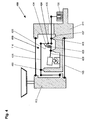
- FIG. 2 shows a schematic representation of a load cell 200 with a further embodiment of the power transmission device 210 in the plan.
- the calibration lever 220 and the parallel-coupled coupling means 224 all elements shown correspond to the elements of FIG. 1 and will not be described below.
- Calibration lever 220 shown includes a first calibration lever arm 221 and a second calibration lever arm 222, with first calibration lever arm 221 extending from calibration weight 123 to hinge point 113 and second calibration lever arm 222 extending between hinge point 113 and fixed partial coupling means 226 of parallel-guided coupling means 224.
- the parallel-guided coupling means 224 has a parallel-guided partial coupling means 225 and a fixed partial coupling means 226, which engage in each other without contact in the unloaded state. As soon as a tensile force is to be transmitted from the fixed partial coupling means 226 to the parallel-guided partial coupling means 225 and thus to the long lever arm 118 of the lever 116, the fixed partial coupling means 226 hooks in the parallel-guided partial coupling means after a short relative displacement of the two along a defined displacement distance 225th
- the calibration weight 123 can also be used to expand the weighing range of the weighing cell 200.
- the weighing range can be maximally doubled if the force acting on the measuring sensor 130 by the calibration weight 123 corresponds to the maximum force.
- the weighing area is then invisibly subdivided into two subareas for the user, wherein in the first subarea no force of the calibration weight 123 acts on the sensor 130 and in the second subarea the calibration weight 123 is coupled to the lever system.
- the accuracy of the Therefore for the higher load range, a lower resolution or a downgrading of the accuracy class can be provided. All the processes described above can be controlled automatically depending on the load by means of the balance electronics, without the user having to worry about which partial area is to be selected.
- the calibration weight 123 can also act more directly on the load receiving area 112, as shown in FIG FIG. 3 is shown.
- This shows a load cell 300 with another embodiment of the power transmission device 310 in the plan.
- the lever mechanism has a lever 316, which is arranged between the load receiving area 112 and the sensor 130.
- the calibration lever 320 having a calibration weight 123 is hingedly connected to the fixed portion 311 and disposed below the load receiving portion 312 with respect to the position of use of the load cell 300.
- the parallel-guided partial coupling means 325 is here connected to the calibration lever 320 and the fixed part coupling means 326 with the load receiving portion 312. The shorter the second lever arm 322 of the calibration lever 320 in relation to The first calibration lever arm 321 is selected, the greater is the calibration force transmitted by the parallel-guided coupling means 324 to the load receiving area 312.
- the parallel-guided coupling means 324 serves to compensate for transverse forces which would occur at a deflection of the sub-coupling means without parallel guidance, since it can then come due to a horizontal displacement to a mutual tension of the bearings 362 and 363 because of different swivel radii r 1 , r 2 . These transverse forces are compensated by the parallel-guided coupling means 324 and in particular by the parallel-guided partial coupling means 325.
- the calibration weight 123 would be coupled via the parallel-guided coupling means 324 directly and not via a parallelogram or a lever mechanism in the measuring system, as indicated here by the arrangement of the fixed part coupling means 326 on the load receiving area 312.
- FIG. 4 shows a schematic representation of a load cell 400 with a further embodiment of the power transmission device 410 in the plan view, which has a arranged between the load receiving portion 112 and the sensor 130 lever mechanism with two levers 436, 437 for reducing the force acting on the load receiving portion 112.
- FIG. 4 has components that are identical to some components in the preceding figures and therefore have the same reference numerals or are not described.
- the first lever 436 is connected to the second lever 437 in a force-transmitting manner by a coupling element 434.
- a parallel-guided coupling means 424 is arranged, which can transmit only compressive forces.
- the fixed partial coupling means 426 of the parallel-guided coupling means 424 is connected to the coupling element 434 and the parallel-guided partial coupling means 425 is connected to the calibration lever 420.
- a torque is generated which loads the bearing points 460, 461 of the levers 436, 437.
- solutions should be sought in which the two lines of force coincide.
- the fixed area 411 has an opening 435, through which the second lever 437 passes, so that the sensor 130 can be arranged on the side of the fixed area 411 facing away from the parallel core 114, 115.
- FIG. 5 shows a schematic representation of a load cell 500 with a further embodiment of the power transmission device 510 in the plan.
- This has a disposed between the load receiving area 112 and the sensor 130 Lever with three levers 536, 537, 538 for reducing the force acting on the load receiving portion 112 force.
- the first lever 536 are connected by means of a second coupling element 539 with the second lever 537 and the second lever 537 by means of a third coupling element 529 with the third lever 538 force-transmitting.
- a parallel-guided coupling means 524 which can transmit only tensile forces, is arranged between the lever mechanism and a calibration lever 520.
- the force is applied to the second coupling element 539, which connects the first lever 536 with the second lever 537, wherein the parallel-guided coupling means 524 not as in FIG. 4 parallel, but in series with the second coupling element 539 is arranged. Due to the serial arrangement, it is avoided that a torque acts on the second coupling element 539 during calibration, as in the case of FIG. 4 can be 434 shown coupling element.
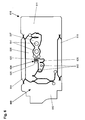
- a monolithic power transmission device 610 is shown in plan view.
- a material block 699 delimited by its contour lines a first lever 636, a second lever 637, a calibration lever 620, a first parallel link 614, a second parallel link 615, the fixed area 611 of the load receiving area 612 are by means of thin, orthogonal to the drawing plane the material block 699 penetrating cut lines and a first coupling element and a second coupling element are formed.
- All of these sectional line formed parts are suitably connected to each other by means of thin line flexure bearings also provided by cutting lines, so that the power transmission device 610 has substantially a load receiving portion 612 guided on the fixed portion 611 and a lever mechanism 636, 637 and a calibration lever 620.
- the second lever 637 is connected by means of a Hebelarmverinrung, not shown, with the sensor, not shown. To fix the Hebelarmverinrung 637 two holes 641 are present in the second lever.
- the calibration lever 620 has two holes 642 on which a calibration weight can be attached.
- a parallel-guided coupling means 624 is arranged, which has a parallel-guided partial coupling means 625 and a fixed partial coupling means 626.
- a first contact point and the second part coupling means 626 formed a second contact point.
- the contact points can be brought into contact with one another for a force transmission and are here aligned substantially parallel to one another.
- FIGS. 7 to 11 show various embodiments of a parallel-guided coupling means, which as in the FIGS. 1 to 6 shown in a power transmission device of a load cell can be arranged.
- the parallel-guided coupling means has a parallel-guided partial coupling means and a fixed partial coupling means, one of which is connected to the load receiving area or the lever mechanism of a power transmission device and the other with the calibration lever.
- FIG. 7 shows a possible embodiment of a parallel-guided coupling means, with which only a compressive force is transferable.
- the parallel-guided coupling means has a fixed partial coupling means 726 and a parallel-guided partial coupling means 725 with two parallel elements 727, 728 arranged parallel to one another.
- the parallel elements 727, 728 are designed here as handlebars with two thin-point bending bearings, but they can also be configured as any other, known to those skilled parallel elements. They are oriented so that they can compensate for transverse forces occurring due to the geometric conditions in a power transmission through the parallel-guided coupling means.
- the parallel-guided partial coupling means 725 must have an internal stability.
- the fixed partial coupling means 726 has a directed against the parallel-guided partial coupling means 725 surface with two protruding projections as the first contact point 744, which are arranged in mirror symmetry with respect to the central longitudinal axis between the two parallel elements 727, 728.
- the parallel-guided partial coupling means 725 has two second contact points 745 directed against the fixed partial coupling means 726, on each of which one of the two contact points 744 can be supported.
- the parallel-guided partial coupling means 725 and the fixed partial coupling means 726 can be aligned with one another during the calibration process by means of this embodiment.
- displacements orthogonal to the central longitudinal axes X of the parallel elements 727, 728 can be prevented.
- the two second contact points 745 are inclined at an obtuse angle to one another on the parallel-guided partial coupling means 725.
- FIGS. 8 to 11 show in each case further embodiments of the parallel-guided coupling means for the transmission of tensile forces.
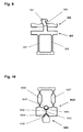
- FIG. 8 shows a parallel-guided coupling means with a parallel-guided partial coupling means 825, which has two Dünnstellenbiegelager parallel element 827, 828, and with a fixed part coupling means 826th
- the two parallel elements 827, 828 are arranged parallel to each other. Between the parallel elements 827, 828, a first tension element 846 is also formed.
- the fixed partial coupling means 826 has a second pulling element 847.
- the first pulling element 846 engages in the second pulling element 847 after a small relative displacement path from one another.
- the first tension member 846 as shown here, a projection and the second tension member 847 have a pan 849.
- the projection to the socket 849 is self-centering due to its shape and the projection with the socket 849 is in contact.
- FIG. 9 shows a further embodiment of the parallel-guided coupling means FIG. 8 in which a parallel-guided partial coupling means 925, a second tension member 947 with a pan and a fixed part coupling means 926, a first tension member 946 having a projection which can mesh for transmitting power, as already in connection with FIG. 8 has been described.
- the parallel-guided Part coupling means 925 has here as a further embodiment of two configured as leaf springs parallel elements 927, 928.
- FIG. 10 shows another parallel-guided coupling means with a parallel-guided partial coupling means 1025 and a fixed partial coupling means 1026.
- the parallel-guided partial coupling means 1025 has centrally between the two thin-point bending bearing having parallel elements 1028, 1027 acting as a pan second tension element 1046 in the form of a depression.
- the fixed part coupling means 1026 has a first pulling element 1046 acting as a projection, which is here designed as a ball or bar.
- the first pulling element 1046 is connected to the fixed part coupling means 1026 by a connecting element 1052.
- the connecting element 1052 is movable and arranged substantially in the interior of the parallel-guided partial coupling means 1025.
- the parallel-guided partial coupling means 1025 may have a recess 1054 on the side of the bushing 1053 opposite the first tension element 1046, into which recess a projection 1055 formed on the fixed part coupling means 1026 may engage.
- FIG. 11 shows a further parallel-guided coupling means with a fixed part coupling means 1126 and a parallel-guided partial coupling means 1125, which has a first pulling element 1146 in the form of a ball or a rod that is connected via a connecting means 1152 with the parallel-guided partial coupling means 1125.
- the fixed part coupling means 1126 has a passage 1153, in which the connecting element 1152 is at least partially disposed, and which is formed on the parallel-guided part coupling means 1125 opposite side of the bushing 1153 as a pan, which is a second tension member 1147.
- the second tension elements shown can be arranged at least partially in each case in the part coupling means having the first tension element, as is the case for the second tension elements Figures 10 and 11 is described.
- FIG. 12 shows another parallel-guided coupling means with which a compressive force can be transmitted.
- the parallel-guided coupling means has a fixed Partial coupling means 1226 and a parallel-guided partial coupling means 1225.
- the fixed part coupling means 1226 has a kind of protruding punch, at its free end a contact point 1244 is formed. This is arranged between the two parallel elements 1227, 1228 of the parallel-guided partial coupling means 1225.
- the contact point 1244 can be brought into contact with a contact point 1245 arranged at the parallel-guided partial coupling means 1225 for force transmission.
Landscapes
- Physics & Mathematics (AREA)
- General Physics & Mathematics (AREA)
- Electromagnetism (AREA)
- Measurement Of Force In General (AREA)
Priority Applications (2)
| Application Number | Priority Date | Filing Date | Title |
|---|---|---|---|
| PL10179300T PL2434264T3 (pl) | 2010-09-24 | 2010-09-24 | Urządzenie przenoszące siłę ze sprzęgalnym odważnikiem kalibracyjnym |
| EP10179300.8A EP2434264B1 (de) | 2010-09-24 | 2010-09-24 | Kraftübertragungsvorrichtung mit koppelbarem Kalibriergewicht |
Applications Claiming Priority (1)
| Application Number | Priority Date | Filing Date | Title |
|---|---|---|---|
| EP10179300.8A EP2434264B1 (de) | 2010-09-24 | 2010-09-24 | Kraftübertragungsvorrichtung mit koppelbarem Kalibriergewicht |
Publications (2)
| Publication Number | Publication Date |
|---|---|
| EP2434264A1 EP2434264A1 (de) | 2012-03-28 |
| EP2434264B1 true EP2434264B1 (de) | 2014-04-02 |
Family
ID=43446530
Family Applications (1)
| Application Number | Title | Priority Date | Filing Date |
|---|---|---|---|
| EP10179300.8A Active EP2434264B1 (de) | 2010-09-24 | 2010-09-24 | Kraftübertragungsvorrichtung mit koppelbarem Kalibriergewicht |
Country Status (2)
| Country | Link |
|---|---|
| EP (1) | EP2434264B1 (pl) |
| PL (1) | PL2434264T3 (pl) |
Families Citing this family (6)
| Publication number | Priority date | Publication date | Assignee | Title |
|---|---|---|---|---|
| PL2533024T3 (pl) | 2011-06-09 | 2014-08-29 | Mettler Toledo Gmbh | Urządzenie przenoszące siłę ze sprzęgalnym odważnikiem kalibracyjnym |
| CN108072442A (zh) * | 2017-11-17 | 2018-05-25 | 长沙开元仪器股份有限公司 | 可自动校准的电子天平 |
| DE102019130625A1 (de) * | 2019-11-13 | 2021-05-20 | Minebea Intec Aachen GmbH & Co. KG | Wägeaufnehmer mit einer Justiergewichtsschaltung |
| DE102020110919B4 (de) * | 2020-04-22 | 2023-12-28 | Sartorius Lab Instruments Gmbh & Co. Kg | Wägesystem |
| CN113588050B (zh) * | 2020-04-30 | 2025-07-18 | 梅特勒-托利多仪器(上海)有限公司 | 称重设备和称重方法 |
| CN116124258A (zh) * | 2023-02-23 | 2023-05-16 | 昆山昆博智能感知产业技术研究院有限公司 | 称重传感器装置 |
Family Cites Families (11)
| Publication number | Priority date | Publication date | Assignee | Title |
|---|---|---|---|---|
| CH593481A5 (pl) | 1975-11-18 | 1977-12-15 | Mettler Instrumente Ag | |
| CH661121A5 (en) | 1983-05-27 | 1987-06-30 | Mettler Instrumente Ag | Electromechanical balance with a lever mechanism and with a connectable calibrating weight |
| DE4427087C2 (de) * | 1994-07-30 | 1996-07-11 | Sartorius Gmbh | Oberschalige Waage |
| US5866854A (en) * | 1996-02-12 | 1999-02-02 | Mettler-Toledo Ag | Calibrating device for a balance |
| DE19820637A1 (de) | 1998-05-08 | 1999-11-11 | Mettler Toledo Gmbh | Waage mit einem Ankopplungsbereich für ein Kalibriergewicht |
| DE10007267C2 (de) * | 2000-01-15 | 2002-08-29 | Sartorius Gmbh | Wägeaufnehmer mit mehreren Übersetzungshebeln |
| JP3761792B2 (ja) | 2000-09-25 | 2006-03-29 | 株式会社クボタ | 校正装置付きロードセル式はかり |
| DE10229016B4 (de) * | 2002-06-28 | 2005-03-31 | Wipotec Wiege- Und Positioniersysteme Gmbh | Schwenklager |
| PL1726926T3 (pl) | 2005-05-26 | 2017-08-31 | Mettler-Toledo Gmbh | Prowadnica równoległa do kompaktowych systemów wagowych |
| EP1752746B1 (de) * | 2005-08-10 | 2008-12-03 | Mettler-Toledo AG | Kalibriergewichtsanordnung für eine elektronische Waage |
| EP1968078B1 (de) | 2007-03-05 | 2010-05-19 | Mettler-Toledo AG | Spule eines Kraftmesssystems und Verfahren zu deren Herstellung |
-
2010
- 2010-09-24 PL PL10179300T patent/PL2434264T3/pl unknown
- 2010-09-24 EP EP10179300.8A patent/EP2434264B1/de active Active
Also Published As
| Publication number | Publication date |
|---|---|
| EP2434264A1 (de) | 2012-03-28 |
| PL2434264T3 (pl) | 2014-08-29 |
Similar Documents
| Publication | Publication Date | Title |
|---|---|---|
| EP2336736B1 (de) | Kraftübertragungsvorrichtung mit koppelbarem Kalibriergewicht | |
| EP2533024B1 (de) | Kraftübertragungsvorrichtung mit koppelbarem Kalibriergewicht | |
| EP2860501B1 (de) | Wägezelle mit einer Vorrichtung zur Korrektur exzentrischer Belastungsfehler und Verfahren zur Korrektur exzentrischer Belastungsfehler | |
| EP2434264B1 (de) | Kraftübertragungsvorrichtung mit koppelbarem Kalibriergewicht | |
| EP2690415B1 (de) | Kraftmessvorrichtung mit Verschiebegewicht | |
| EP2041531B1 (de) | Oberschalige waage mit ecklastsensor | |
| EP0789232B1 (de) | Kalibriervorrichtung für eine Waage | |
| EP2153185B1 (de) | Justierbare parallelführung für kompakte gravimetrische messinstrumente | |
| EP2784454B1 (de) | Wägezellendiagnostik | |
| EP1332342B1 (de) | Wägeaufnehmer mit justiergewicht | |
| DE60130529T2 (de) | Elektronische Waage | |
| EP2120023A1 (de) | Gekapselte Wägezelle mit Eckenlasteinstellung | |
| EP2673602B1 (de) | Wägezelle sowie verfahren zum justieren einer wägezelle | |
| EP2615433B1 (de) | Vorrichtung und Verfahren zur Justierung des Eckenlastfehlers einer Parallelführung | |
| DE102019130625A1 (de) | Wägeaufnehmer mit einer Justiergewichtsschaltung | |
| EP3667265B1 (de) | Kalibriergewichtsanordnung für ein gravimetrisches messgerät | |
| DE19605087C2 (de) | Kalibriervorrichtung für eine Waage | |
| EP2610596B2 (de) | Brückenelement zur Ausbildung einer Waage | |
| EP2610595B1 (de) | Wägebrücke | |
| DE102023132262B4 (de) | Wägesystem mit Astasierungshebel | |
| CH664219A5 (de) | Plattformwaage. | |
| EP2175249A1 (de) | Kraftmessvorrichtung | |
| DE10202951A1 (de) | Kraftmesszelle | |
| WO2008061763A2 (de) | Torsionsunanfälliger kraftaufnehmer mit steg in zentralöffnung | |
| DE102025100938B3 (de) | Wägesystem mit Astasierungshebel |
Legal Events
| Date | Code | Title | Description |
|---|---|---|---|
| PUAI | Public reference made under article 153(3) epc to a published international application that has entered the european phase |
Free format text: ORIGINAL CODE: 0009012 |
|
| AK | Designated contracting states |
Kind code of ref document: A1 Designated state(s): AL AT BE BG CH CY CZ DE DK EE ES FI FR GB GR HR HU IE IS IT LI LT LU LV MC MK MT NL NO PL PT RO SE SI SK SM TR |
|
| AX | Request for extension of the european patent |
Extension state: BA ME RS |
|
| 17P | Request for examination filed |
Effective date: 20120914 |
|
| GRAP | Despatch of communication of intention to grant a patent |
Free format text: ORIGINAL CODE: EPIDOSNIGR1 |
|
| RAP3 | Party data changed (applicant data changed or rights of an application transferred) |
Owner name: METTLER-TOLEDO AG |
|
| RIC1 | Information provided on ipc code assigned before grant |
Ipc: G01G 21/24 20060101AFI20131010BHEP |
|
| INTG | Intention to grant announced |
Effective date: 20131031 |
|
| GRAS | Grant fee paid |
Free format text: ORIGINAL CODE: EPIDOSNIGR3 |
|
| GRAA | (expected) grant |
Free format text: ORIGINAL CODE: 0009210 |
|
| AK | Designated contracting states |
Kind code of ref document: B1 Designated state(s): AL AT BE BG CH CY CZ DE DK EE ES FI FR GB GR HR HU IE IS IT LI LT LU LV MC MK MT NL NO PL PT RO SE SI SK SM TR |
|
| REG | Reference to a national code |
Ref country code: GB Ref legal event code: FG4D Free format text: NOT ENGLISH |
|
| REG | Reference to a national code |
Ref country code: AT Ref legal event code: REF Ref document number: 660398 Country of ref document: AT Kind code of ref document: T Effective date: 20140415 Ref country code: CH Ref legal event code: EP |
|
| REG | Reference to a national code |
Ref country code: IE Ref legal event code: FG4D Free format text: LANGUAGE OF EP DOCUMENT: GERMAN |
|
| REG | Reference to a national code |
Ref country code: DE Ref legal event code: R096 Ref document number: 502010006531 Country of ref document: DE Effective date: 20140515 |
|
| REG | Reference to a national code |
Ref country code: NL Ref legal event code: VDEP Effective date: 20140402 |
|
| REG | Reference to a national code |
Ref country code: PL Ref legal event code: T3 |
|
| REG | Reference to a national code |
Ref country code: LT Ref legal event code: MG4D |
|
| PG25 | Lapsed in a contracting state [announced via postgrant information from national office to epo] |
Ref country code: IS Free format text: LAPSE BECAUSE OF FAILURE TO SUBMIT A TRANSLATION OF THE DESCRIPTION OR TO PAY THE FEE WITHIN THE PRESCRIBED TIME-LIMIT Effective date: 20140802 Ref country code: BG Free format text: LAPSE BECAUSE OF FAILURE TO SUBMIT A TRANSLATION OF THE DESCRIPTION OR TO PAY THE FEE WITHIN THE PRESCRIBED TIME-LIMIT Effective date: 20140702 Ref country code: NL Free format text: LAPSE BECAUSE OF FAILURE TO SUBMIT A TRANSLATION OF THE DESCRIPTION OR TO PAY THE FEE WITHIN THE PRESCRIBED TIME-LIMIT Effective date: 20140402 Ref country code: NO Free format text: LAPSE BECAUSE OF FAILURE TO SUBMIT A TRANSLATION OF THE DESCRIPTION OR TO PAY THE FEE WITHIN THE PRESCRIBED TIME-LIMIT Effective date: 20140702 Ref country code: LT Free format text: LAPSE BECAUSE OF FAILURE TO SUBMIT A TRANSLATION OF THE DESCRIPTION OR TO PAY THE FEE WITHIN THE PRESCRIBED TIME-LIMIT Effective date: 20140402 Ref country code: CZ Free format text: LAPSE BECAUSE OF FAILURE TO SUBMIT A TRANSLATION OF THE DESCRIPTION OR TO PAY THE FEE WITHIN THE PRESCRIBED TIME-LIMIT Effective date: 20140402 Ref country code: CY Free format text: LAPSE BECAUSE OF FAILURE TO SUBMIT A TRANSLATION OF THE DESCRIPTION OR TO PAY THE FEE WITHIN THE PRESCRIBED TIME-LIMIT Effective date: 20140402 Ref country code: FI Free format text: LAPSE BECAUSE OF FAILURE TO SUBMIT A TRANSLATION OF THE DESCRIPTION OR TO PAY THE FEE WITHIN THE PRESCRIBED TIME-LIMIT Effective date: 20140402 Ref country code: GR Free format text: LAPSE BECAUSE OF FAILURE TO SUBMIT A TRANSLATION OF THE DESCRIPTION OR TO PAY THE FEE WITHIN THE PRESCRIBED TIME-LIMIT Effective date: 20140703 |
|
| PG25 | Lapsed in a contracting state [announced via postgrant information from national office to epo] |
Ref country code: ES Free format text: LAPSE BECAUSE OF FAILURE TO SUBMIT A TRANSLATION OF THE DESCRIPTION OR TO PAY THE FEE WITHIN THE PRESCRIBED TIME-LIMIT Effective date: 20140402 Ref country code: LV Free format text: LAPSE BECAUSE OF FAILURE TO SUBMIT A TRANSLATION OF THE DESCRIPTION OR TO PAY THE FEE WITHIN THE PRESCRIBED TIME-LIMIT Effective date: 20140402 Ref country code: SE Free format text: LAPSE BECAUSE OF FAILURE TO SUBMIT A TRANSLATION OF THE DESCRIPTION OR TO PAY THE FEE WITHIN THE PRESCRIBED TIME-LIMIT Effective date: 20140402 Ref country code: HR Free format text: LAPSE BECAUSE OF FAILURE TO SUBMIT A TRANSLATION OF THE DESCRIPTION OR TO PAY THE FEE WITHIN THE PRESCRIBED TIME-LIMIT Effective date: 20140402 |
|
| PG25 | Lapsed in a contracting state [announced via postgrant information from national office to epo] |
Ref country code: PT Free format text: LAPSE BECAUSE OF FAILURE TO SUBMIT A TRANSLATION OF THE DESCRIPTION OR TO PAY THE FEE WITHIN THE PRESCRIBED TIME-LIMIT Effective date: 20140804 |
|
| REG | Reference to a national code |
Ref country code: DE Ref legal event code: R097 Ref document number: 502010006531 Country of ref document: DE |
|
| PG25 | Lapsed in a contracting state [announced via postgrant information from national office to epo] |
Ref country code: EE Free format text: LAPSE BECAUSE OF FAILURE TO SUBMIT A TRANSLATION OF THE DESCRIPTION OR TO PAY THE FEE WITHIN THE PRESCRIBED TIME-LIMIT Effective date: 20140402 Ref country code: SK Free format text: LAPSE BECAUSE OF FAILURE TO SUBMIT A TRANSLATION OF THE DESCRIPTION OR TO PAY THE FEE WITHIN THE PRESCRIBED TIME-LIMIT Effective date: 20140402 Ref country code: RO Free format text: LAPSE BECAUSE OF FAILURE TO SUBMIT A TRANSLATION OF THE DESCRIPTION OR TO PAY THE FEE WITHIN THE PRESCRIBED TIME-LIMIT Effective date: 20140402 Ref country code: DK Free format text: LAPSE BECAUSE OF FAILURE TO SUBMIT A TRANSLATION OF THE DESCRIPTION OR TO PAY THE FEE WITHIN THE PRESCRIBED TIME-LIMIT Effective date: 20140402 |
|
| PLBE | No opposition filed within time limit |
Free format text: ORIGINAL CODE: 0009261 |
|
| STAA | Information on the status of an ep patent application or granted ep patent |
Free format text: STATUS: NO OPPOSITION FILED WITHIN TIME LIMIT |
|
| 26N | No opposition filed |
Effective date: 20150106 |
|
| PG25 | Lapsed in a contracting state [announced via postgrant information from national office to epo] |
Ref country code: IT Free format text: LAPSE BECAUSE OF FAILURE TO SUBMIT A TRANSLATION OF THE DESCRIPTION OR TO PAY THE FEE WITHIN THE PRESCRIBED TIME-LIMIT Effective date: 20140402 |
|
| REG | Reference to a national code |
Ref country code: DE Ref legal event code: R097 Ref document number: 502010006531 Country of ref document: DE Effective date: 20150106 |
|
| PG25 | Lapsed in a contracting state [announced via postgrant information from national office to epo] |
Ref country code: MC Free format text: LAPSE BECAUSE OF FAILURE TO SUBMIT A TRANSLATION OF THE DESCRIPTION OR TO PAY THE FEE WITHIN THE PRESCRIBED TIME-LIMIT Effective date: 20140402 Ref country code: LU Free format text: LAPSE BECAUSE OF FAILURE TO SUBMIT A TRANSLATION OF THE DESCRIPTION OR TO PAY THE FEE WITHIN THE PRESCRIBED TIME-LIMIT Effective date: 20140924 |
|
| GBPC | Gb: european patent ceased through non-payment of renewal fee |
Effective date: 20140924 |
|
| REG | Reference to a national code |
Ref country code: IE Ref legal event code: MM4A |
|
| REG | Reference to a national code |
Ref country code: FR Ref legal event code: ST Effective date: 20150529 |
|
| PG25 | Lapsed in a contracting state [announced via postgrant information from national office to epo] |
Ref country code: BE Free format text: LAPSE BECAUSE OF NON-PAYMENT OF DUE FEES Effective date: 20140930 |
|
| PG25 | Lapsed in a contracting state [announced via postgrant information from national office to epo] |
Ref country code: SI Free format text: LAPSE BECAUSE OF FAILURE TO SUBMIT A TRANSLATION OF THE DESCRIPTION OR TO PAY THE FEE WITHIN THE PRESCRIBED TIME-LIMIT Effective date: 20140402 Ref country code: GB Free format text: LAPSE BECAUSE OF NON-PAYMENT OF DUE FEES Effective date: 20140924 |
|
| PG25 | Lapsed in a contracting state [announced via postgrant information from national office to epo] |
Ref country code: FR Free format text: LAPSE BECAUSE OF NON-PAYMENT OF DUE FEES Effective date: 20140930 Ref country code: IE Free format text: LAPSE BECAUSE OF NON-PAYMENT OF DUE FEES Effective date: 20140924 |
|
| REG | Reference to a national code |
Ref country code: CH Ref legal event code: PFA Owner name: METTLER-TOLEDO GMBH, CH Free format text: FORMER OWNER: METTLER-TOLEDO AG, CH |
|
| PG25 | Lapsed in a contracting state [announced via postgrant information from national office to epo] |
Ref country code: SM Free format text: LAPSE BECAUSE OF FAILURE TO SUBMIT A TRANSLATION OF THE DESCRIPTION OR TO PAY THE FEE WITHIN THE PRESCRIBED TIME-LIMIT Effective date: 20140402 |
|
| PG25 | Lapsed in a contracting state [announced via postgrant information from national office to epo] |
Ref country code: MT Free format text: LAPSE BECAUSE OF FAILURE TO SUBMIT A TRANSLATION OF THE DESCRIPTION OR TO PAY THE FEE WITHIN THE PRESCRIBED TIME-LIMIT Effective date: 20140402 |
|
| PG25 | Lapsed in a contracting state [announced via postgrant information from national office to epo] |
Ref country code: TR Free format text: LAPSE BECAUSE OF FAILURE TO SUBMIT A TRANSLATION OF THE DESCRIPTION OR TO PAY THE FEE WITHIN THE PRESCRIBED TIME-LIMIT Effective date: 20140402 Ref country code: HU Free format text: LAPSE BECAUSE OF FAILURE TO SUBMIT A TRANSLATION OF THE DESCRIPTION OR TO PAY THE FEE WITHIN THE PRESCRIBED TIME-LIMIT; INVALID AB INITIO Effective date: 20100924 |
|
| REG | Reference to a national code |
Ref country code: AT Ref legal event code: MM01 Ref document number: 660398 Country of ref document: AT Kind code of ref document: T Effective date: 20150924 |
|
| PG25 | Lapsed in a contracting state [announced via postgrant information from national office to epo] |
Ref country code: AT Free format text: LAPSE BECAUSE OF NON-PAYMENT OF DUE FEES Effective date: 20150924 |
|
| REG | Reference to a national code |
Ref country code: DE Ref legal event code: R081 Ref document number: 502010006531 Country of ref document: DE Owner name: METTLER-TOLEDO GMBH, CH Free format text: FORMER OWNER: METTLER-TOLEDO AG, GREIFENSEE, CH |
|
| PG25 | Lapsed in a contracting state [announced via postgrant information from national office to epo] |
Ref country code: MK Free format text: LAPSE BECAUSE OF FAILURE TO SUBMIT A TRANSLATION OF THE DESCRIPTION OR TO PAY THE FEE WITHIN THE PRESCRIBED TIME-LIMIT Effective date: 20140402 |
|
| PG25 | Lapsed in a contracting state [announced via postgrant information from national office to epo] |
Ref country code: AL Free format text: LAPSE BECAUSE OF FAILURE TO SUBMIT A TRANSLATION OF THE DESCRIPTION OR TO PAY THE FEE WITHIN THE PRESCRIBED TIME-LIMIT Effective date: 20140402 |
|
| REG | Reference to a national code |
Ref country code: CH Ref legal event code: U11 Free format text: ST27 STATUS EVENT CODE: U-0-0-U10-U11 (AS PROVIDED BY THE NATIONAL OFFICE) Effective date: 20251001 |
|
| PGFP | Annual fee paid to national office [announced via postgrant information from national office to epo] |
Ref country code: DE Payment date: 20250926 Year of fee payment: 16 |
|
| PGFP | Annual fee paid to national office [announced via postgrant information from national office to epo] |
Ref country code: PL Payment date: 20250901 Year of fee payment: 16 |
|
| PGFP | Annual fee paid to national office [announced via postgrant information from national office to epo] |
Ref country code: CH Payment date: 20251001 Year of fee payment: 16 |