EP2433510A2 - Dispositif et procédé de mesure de propriétés d'un tronçon de matériaux mobile, in particulier d'une tige de cigarette, avec un résonateur à microondes avec réception infradyne - Google Patents
Dispositif et procédé de mesure de propriétés d'un tronçon de matériaux mobile, in particulier d'une tige de cigarette, avec un résonateur à microondes avec réception infradyne Download PDFInfo
- Publication number
- EP2433510A2 EP2433510A2 EP11181348A EP11181348A EP2433510A2 EP 2433510 A2 EP2433510 A2 EP 2433510A2 EP 11181348 A EP11181348 A EP 11181348A EP 11181348 A EP11181348 A EP 11181348A EP 2433510 A2 EP2433510 A2 EP 2433510A2
- Authority
- EP
- European Patent Office
- Prior art keywords
- signal
- frequency
- microwave
- microwave resonator
- output
- Prior art date
- Legal status (The legal status is an assumption and is not a legal conclusion. Google has not performed a legal analysis and makes no representation as to the accuracy of the status listed.)
- Withdrawn
Links
Images


Classifications
-
- G—PHYSICS
- G01—MEASURING; TESTING
- G01N—INVESTIGATING OR ANALYSING MATERIALS BY DETERMINING THEIR CHEMICAL OR PHYSICAL PROPERTIES
- G01N22/00—Investigating or analysing materials by the use of microwaves or radio waves, i.e. electromagnetic waves with a wavelength of one millimetre or more
- G01N22/04—Investigating moisture content
Definitions
- the invention relates to a device for processing and measuring properties of a moving strand of material in the tobacco processing industry, comprising a microwave measuring device having a microwave resonator through which the material strand is conveyed or is conveyed, the microwave resonator on the input side with one of a microwave generator with a an output frequency f 0 generated measured signal is acted upon or acted upon.
- the invention further relates to a corresponding microwave measuring device and to a method for processing and measuring properties of a material strand of the tobacco-processing industry.
- the invention relates in particular to the field of strand formation and strand processing in the tobacco processing industry, ie the production of cigarette rods and filter strands in Rod makers.
- a cigarette rod is produced by first popping tobacco onto a rope conveyor, wrapping the tobacco rope with a strip of cigarette paper, and then cutting it from the tobacco rope into cigarettes of multiple length of use.
- the forming of the tobacco or filter strand and the subsequent cutting or cutting of the strand takes place at high speed.
- Typical of today's cigarette and filter making machines strand speeds of 10 m / s, with 100 mm section length followed by a cutting rate of 100 per second.
- the quality of the cigarettes depends on the condition of the tobacco in the cigarette rod. For this reason, it is intended to measure the moisture and the density of the tobacco in the cigarette rod and in particular to control the density. Furthermore, in the case of sudden and short-term signal fluctuations, the presence of foreign bodies is concluded, with the corresponding strand sections subsequently being rejected.
- the measurement by means of a microwave resonator makes use of the physical fact that the resonance curve of the microwave field changes in the microwave resonator in the presence of a strand of material in the microwave resonator.
- the complex dielectric constant of the material strand guided through the resonator is measured.
- the complex dielectric constant has a real part and an imaginary part and an amount and a phase, respectively.
- the two characteristics of the complex dielectric constants contain the information on the density and the water content of the strand. Changes in density or water content lead to the characteristic changes of the two characteristic values and thus the resonance curve of the microwave resonator.
- the resonance curve widens. Changes in the density and changes in the moisture content of the material strand each generate their own specific changes in the position, height and width of the resonance curve. Therefore, if at least two measured values of the resonance curve are measured, the density and the humidity can be determined independently within the scope of the measuring accuracy and the correlations of the functional dependencies of the measured values of strand density and strand moisture.
- An evaluation circuit for evaluating a microwave resonator measuring signal is off EP 0 791 823 A2 known, the disclosure of which is also to be incorporated in full content in the present patent application.
- Several independent measures are generated by supplying the resonator with microwaves of at least two different frequencies, with which a part the resonance curve is sampled. Displacements of the resonance are detected by comparing the resonance curves of the resonator, which are uninfluenced and influenced by the substance, and the attenuation is detected by comparing the amplitudes of the resonance curves at the frequencies of the supplied microwaves. From the height of the measured signal and the slope of the flank density and humidity of the tobacco rod are reconstructed.
- the fundamental frequency of the microwave signal is adjusted with respect to the resonance curve for the unloaded microwave resonator so that it lies at the inflection point of one of the edges of the resonance curve.
- the modulated at least two frequencies are on the same slope above and below the inflection point.
- the input frequencies are 5.79 GHz and 5.81 GHz, ie 5.8 GHz ⁇ 10 MHz. Between the two frequencies is switched every 5 ⁇ s, so with a frequency of 100 kHz.
- the microwave output signal is rectified via a circulator and a microwave diode and forwarded via an analog-to-digital converter to an evaluation arrangement.
- microwave diodes in particular Schottky diodes. These diodes have an individual non-linear and temperature-dependent characteristic that causes systematic inaccuracies that can only be incompletely corrected by temperature measurements. This fact limits the measurement accuracy and requires an individual adjustment.
- the invention has the object, therefore, to provide a device, a measuring device and a method for processing and measuring properties of a high-speed longitudinal axial moving material strand of the tobacco processing industry, with which the aforementioned accuracy requirements better than previously observed become.
- a device for processing and measuring properties of a particular longitudinal axial moving strand of material of the tobacco processing industry comprising a microwave measuring device having a microwave resonator through which the material strand is conveyed or conveyed, the microwave resonator on the input side with one of a microwave generator with a generated at an output frequency f 0 measurement signal is applied or acted upon, which is further developed in that at least one analysis arrangement is provided which comprises a series circuit of a mixer, a low-pass filter and an analog-to-digital converter, wherein the mixer is connected to a port of the microwave resonator, and an output of a local oscillator and is formed by mixing the transmitted or reflected by the microwave measuring signal of frequency f 0 and a he from the local oscillator have been generating signal of the local frequency f LO to produce a difference signal of a frequency f IM , where f IM is smaller than f 0 and the amount of difference of the frequencies f 0 and f
- the invention is based on the basic idea that in the device according to the invention by means of a heterodyne method the reflected or transmitted measurement signal is modulated down to the intermediate frequency f IM while maintaining the amplitude and the phase.
- the intermediate frequency f IM is not in the microwave range, but has a much smaller frequency, in particular between 100 kHz and 100 MHz, preferably between 1 and 20 MHz.
- This signal is, in contrast to the microwave signal, which for example has a frequency of about 6 GHz, a direct analog-to-digital conversion available with available fast A / D converters, so that nonlinearities of analog components, as they are generated by a microwave diode , be avoided. Because of the correspondingly larger signal amplitude, drift and tolerance influences are minimized and thus cycle times between system checks and recalibrations are lengthened.
- the processing of the material strand may be, for example, the production of a cigarette rod or a filter strand, the addition of additives, the wrapping of the strand with a wrapping paper and / or the cutting to length of cigarettes or filter plugs, or the production of a strand of textile fibers and the stretching of the strand ,
- the measurement results can be used to control the manufacturing process and / or the processing process so that a constant strand density and strand moisture is achieved, or to exclude parts of the strand whose density or moisture outside specified parameters, from further processing.
- the resonance behavior of the resonator can be measured in a reflection arrangement in which only one port on the resonator is used for coupling in a microwave signal and for the measurement, or in transmission arrangement, in which a port on the microwave resonator be used for coupling and another port for the measurement of the transmitted signal.
- the parameter S 11 describes the reflection at the input port of the resonator as a function of the frequency and the S 21 the transmission properties from the input port to the output port.
- Both S-parameters are complex-valued functions of the frequency as well as the complex valence permittivity of the strand.
- a frequency mixture of signals is generated which consists of the fundamental frequency f 0 and the sidebands f 0 + f LO as the upper sideband and
- At least two, in particular similar, analysis arrangements each having a series connection, each comprising a mixer, a low-pass filter and an analog-to-digital converter, are provided, wherein an analysis arrangement receives a measurement signal transmitted by the microwave resonator, and a another analysis device receives a measurement signal reflected by the microwave resonator.
- an analysis arrangement receives a measurement signal transmitted by the microwave resonator
- a another analysis device receives a measurement signal reflected by the microwave resonator.
- both the S 21 and the S 11 parameters are measured with the aid of the heterodyne modulation method used according to the invention.
- the larger number of readings allows further increase in the accuracy of the determination of density and moisture of the material strand.
- Both analysis arrangements are preferably guided on a downstream common evaluation device.
- an isolator, a circulator, a directional coupler, another signal divider and / or an attenuator is arranged between the microwave generator and the microwave resonator.
- these components prevent a disturbance of the generator due to reflected microwave power.
- a suitable attenuator has an attenuation of, for example, about 6 dB.
- an insulator, a circulator and / or an attenuator is arranged in particular between the output of the microwave resonator and the input of the mixer.
- the analysis arrangements with the series circuits are identical in each case, so that direct comparisons are possible.
- the low-pass filters have the same filter characteristics and the analog-to-digital converters are matched to one another, in particular in their threshold values and dynamic ranges and factors.
- a phase detector and a control device connected to the phase detector are provided, wherein the phase detector receives the output signal of the low-pass filter of the analysis arrangement receiving the part of the output signal of the frequency f 0 coupled out on the input side of the isolator or circulator, the control device being designed to determine the local frequency f LO of the local oscillator to control so that a phase difference between the intermediate frequency signal of the frequency f IM and a externally supplied clock signal of the frequency f clock is equal to zero.
- a control device for tracking the output frequency f 0 according to a momentary resonance frequency in the microwave resonator.
- the tracking the introduced into the microwave resonator output frequency f 0 after the current resonant frequency in the microwave resonator has several advantages.
- the shape of the electric field used for the measurement is ideally axially aligned, so that the measurement accuracy is no longer location-or position-dependent. For example, foreign bodies in the strand are recognized equally well regardless of their position.
- the microwave amplitude of the transmitted signal is maximum in resonance at any given attenuation in the resonator. Defects caused by component influences are thereby minimized.
- control device realizes the frequency tracking on the basis of the measured values of the analog-to-digital converters arriving in real time, a quasi-continuous and quasi-instantaneous frequency tracking is possible, which therefore has a minimum time delay.
- the control device is designed to use the value of the phase and / or the amplitude of the transmitted or reflected signal as a controlled variable, wherein a value of the phase of zero and / or an amplitude maximum or an amplitude minimum is desired.
- the phases of both the transmitted signal and the reflected signal have a zero crossing.
- the frequency characteristics of the two phases around the zero crossing have a largely linear course. For this reason, the phases or the zero crossing of the phases are very well suited as a controlled variable for frequency tracking.
- the information about the phase is after Fractions of milliseconds present, so that a readjustment of the injected into the microwave resonator frequency after the resonant frequency quasi-instantaneous occurs. In this period, for example, a tobacco rod is moved only by fractions of a millimeter.
- an evaluation device for evaluating the output signals of the one or more analog-to-digital converters, wherein the evaluation device is integrated in particular in a microprocessor or in the control device.
- the evaluation device is preferably connected downstream of the analog-to-digital converters.
- a microwave measuring device for a device for processing and measuring properties of a material strand of the tobacco processing industry moving, particularly at high speed, longitudinally, as described above, comprising a microwave resonator, by means of which the material strand can be conveyed, wherein the microwave resonator on the input side is acted upon or acted upon by a microwave generator with a generated at an output frequency f 0 measurement signal, which is further developed in that at least one analysis arrangement is provided which comprises a series circuit of a mixer, a low-pass filter and an analog Digital converter comprises, wherein the mixer is connected to a port of the microwave resonator and to an output of a local oscillator and is formed by mixing the microwave resonator transmitted or reflected Me sssignals the frequency f 0 and a signal generated by the local oscillator of the local frequency f LO to produce a difference signal of a frequency f IM , where f IM is smaller than f 0 and the amount
- the microwave measuring device has the same properties, features and advantages as the device according to the invention.
- the object underlying the invention is also achieved by a method for processing and measuring properties of a material strand of the tobacco-processing industry, which is conveyed by a microwave resonator, wherein a measurement signal is generated with an output frequency f 0 and introduced into the microwave resonator.
- This method corresponds to the method performed in the device according to the invention and the measuring device according to the invention based on a heterodyne modulation method.
- the inventive method also offers the advantages according to the invention, in particular the independence of non-linear characteristics of analog components, such as Schottky diodes, and the resulting insensitivity of the accuracy of small signal amplitudes.
- the inventive method provides the data from which the scattering parameters S 11 and / or S 21 are measured, in terms of amplitude and / or phase or real part and / or imaginary part. Amplitudes and phase are contained in a signal of the comparatively low intermediate frequency f IM , which is accessible to a direct analog-to-digital conversion, so that the digital output values already contain the required information about amplitude and phase.
- the microwave resonator output signal of the frequency f 0 modulated down to the intermediate frequency f IM and a low-pass filter to an analog Digital converter transferred is digitized as a direct reference value and serves as a comparison value for the measurement signals of the reflected and / or transmitted signal.
- the signal is shielded by means of the isolator or circulator and / or an attenuator of reflected signals.
- the one or more analog-to-digital converters and / or the oscillator which generates the output signal of the frequency f 0 and / or the local oscillator are synchronized to a frequency-stabilized time signal.
- the local frequency of the local oscillator via a phase detector and a control device is controlled so that a phase difference between the intermediate frequency signal of the frequency f IM and a externally supplied clock signal f clock is equal to zero.
- a digitizable signal of the intermediate frequency f IM with constant frequency and a phase position which does not depend on relative phase shifts between the output signal f 0 and the local oscillator signal f LO , but only on the phase shift in the microwave resonator.
- a regulation of the output frequency f 0 takes place at a momentary resonance frequency in the microwave resonator.
- the control takes place on the basis of a phase of a transmitted signal, wherein by adjusting the output frequency f 0 a value of the phase of zero is desired. This corresponds to the control already described above based on the zero crossing of the phase curve of the S 11 component or the S 21 component. This alternative is very accurate and very fast.
- the control takes place based on the position of a maximum or minimum of a transmitted and / or reflected signal, the output frequency is periodically switched between at least two values which are adjusted so that the output frequency f 0 alternately above and is below the resonance maximum or minimum, with the particular aim of achieving the same signal amplitude at both frequencies or at two of the frequencies
- the mixture with the tracked local oscillator signal f LO then gives a signal with a constant frequency f IM , in the cycle of switching the frequency f 0 changes its amplitude and phase.
- the controlled variable in this case is a minimum or vanishing difference in amplitude in both cases. Since drifting of the resonant frequency leads to a characteristic difference between the amplitudes at both frequencies, which is positive or negative, this controlled variable is also well suited for tracking the excitation frequency after the resonant frequency in the microwave resonator.
- An alternative control advantageously provides for a measurement of the S 21 parameter to control a maximum signal amplitude and / or a measurement of the S 11 parameter to a minimum signal amplitude.
- the devices, measuring devices and methods according to the invention are advantageously applicable, for example in the textile industry, except in the tobacco processing industry, for example in the spinning preparation, when cotton and plastic fibers are aligned and homogenized in carding and drawing devices.
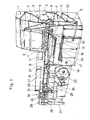
- Fig. 1 explains the basic structure of a cigarette rod machine of the type "PROTOS" of the applicant.
- a pre-distributor 2 is charged in portions with loose tobacco.
- a removal roller 3 of the pre-distributor 2 controlled supplements a reservoir 4 with tobacco, from which a trained as an endless belt vertical conveyor 5 takes tobacco and feeds a stowage 6.
- From the storage shaft 6 takes a pin roller 7 a uniform tobacco stream, which is knocked out by a rollover roller 8 from the pins of the pin roller 7 and spun on a guided as an endless belt and circulating at a constant speed spreading cloth 9.
- a formed on the spreading cloth 9 tobacco fleece is thrown into a sighting device 11 which generates an air curtain, the larger or heavy tobacco particles pass, while all other tobacco particles are directed by the air flow of the air curtain in a funnel formed by a pin roller 12 and a wall 13 funnel 14 , From the pin roller 12, the tobacco is thrown into a tobacco channel 16 against a strand conveyor 17, on which the tobacco is held by means sucked into a vacuum chamber 18 air and aufauert as tobacco rod.
- An equalizer or trimmer 19 consisting essentially of a pair of rotating disks arranged in the plane of the transport direction of the tobacco rod and a deflector, removes excess tobacco from the tobacco rod and cuts the tobacco rod thus formed to a desired thickness.
- the tobacco rod is placed on a run in synchronized cigarette paper strip 21, which is subtracted from a reel 22 and is guided by a printing unit 23.
- the cigarette paper strip 21 is placed on a driven format tape 24, which transports the tobacco rod and the cigarette paper strip 21 through a format 26, in which the cigarette paper strip is folded around the tobacco rod, so that still protrudes an edge, by a Glimapparat, not shown in a known manner is glued.
- the adhesive seam is closed and dried by a Tandemnahtplätte 27.
- a thus formed cigarette rod 28 passes through a strand density meter 29, which controls the Egalisator 19 and is cut by a knife apparatus 31 in double-length cigarettes 32. These are transferred from a controlled arms 33 having transfer device 34 a transfer drum 36 of a filter attachment machine 37, on the cutting drum 38, they are shared with a circular blade in single cigarettes. Endless conveyor belts 39, 41 convey excess tobacco into a container 42 arranged below the storage container 4, from which the recirculated tobacco is removed again from the vertical conveyor 5.
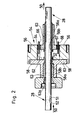
- Fig. 2 shows a schematic cross-sectional view of a suitable resonator housing.
- the resonator housing 54 has a hollow body in the form of a hollow cylinder 56, whose interior or resonator space 57 is arranged symmetrically to the cigarette rod 28.
- a lid 58 is bolted to close.
- the resonator chamber 57 of the resonator housing 54 can be vapor-deposited with a thin gold layer 62, which reliably prevents corrosion formation impairing the measured value constancy and at the same time, since it conducts electricity well, limits a damaging skin effect.
- a protective tube 63 For the mechanical termination of the resonator chamber 57 with respect to the cigarette rod 28 and for the purpose of preventing soiling of the resonator chamber 57, a protective tube 63, advantageously made of a substance of the polyaryl ether ketone (PAEK) group, is used.
- PAEK polyaryl ether ketone
- PEEK polyetheretherketone
- the resonator housing 54 extends outside the resonator chamber 57 tubular (56 a, 58 a) on both sides in the direction of the strand 28 to the outside to prevent the escape of microwaves from the resonator 57. It also extends tubular (56b, 58b) slightly inwards.
- coupling antenna 66 For coupling the microwave generated by a microwave generator used by an insulating ring 64 from the hollow cylinder 56 coupling antenna 66.
- the frequency of the introduced microwave signal is preferably chosen so that, in resonance, the amplitude of the microwave field in the cavity 57 is a maximum in the center, i. has at the location of the cigarette rod 28. If the introduced frequency does not correspond to the resonant frequency, the amplitude at the location of the launch antenna 66 is maximum and decreases toward the output antenna 68. In this case, the field over the cross section of the cigarette rod 28 has a decreasing amplitude curve, is therefore inhomogeneous.
- FIGS. 3 and 4 the amplitude and the phase of the scattering parameters S 11 and S 21 of an ideal lossless resonator are shown in a simulation.
- the X-axes represent the frequency of the introduced microwave signal and range between 5 GHz and 6.5 GHz.
- the self-damping of the uncoated or empty resonator is assumed to be zero in the simulation.
- Fig. 3 the relative amplitude is shown on the y-axis with values between 0 and 1.
- the unloaded resonator correspond to the curves designated by the reference numerals 69a 0 and 69b 0 .
- 69a 0 represents the course of the frequency-dependent transmitted component, ie the S 21 parameter, which has a maximum with a value of 1 at about 6.23 GHz.
- the corresponding reflection curve for the scattering parameter S 11 with unloaded resonator with the reference numeral 69 b 0 has at this point a minimum with the value 0. Outside this minimum, the parameter S 11 has a value close to 1, so there is almost complete reflection.
- the resonance frequency shifts towards a lower frequency, in the example shown at approximately 5.8 GHz.
- the two resonance curves broaden.
- the amplitude of S 21 decreases in resonance, that of S 11 increases.
- the curve of the S 21 parameter only reaches a maximum of approximately 0.7, while the reflection, ie the S 11 parameter, in which the resonance increases to 0.3.
- 2 ) 0.5 in the entire frequency range has the value 1, while in the lossy case in the Resonance has an amount that is smaller than 1, wherein the minimum is reached at the resonant frequency.
- the difference to 1 is a measure of the power dissipation converted in the resonator.
- Fig. 4 are the phase curves to the in Fig. 3 shown resonance curves in the loaded and unloaded state.
- the phase curve 70a 0 of the S 21 parameter which starts at low frequencies with the value + ⁇ / 2
- the corresponding S 11 parameter 70b 0 starts with a small negative value and approaches the resonance frequency so that its value decreases in the direction of - ⁇ / 2.
- the phase When passing through the resonance frequency, the phase reverses and assumes the value + ⁇ / 2. At further higher frequencies, the value decreases again in the direction of 0.
- an ideal microwave resonator is adopted without any losses.
- phase curve 70a of the S 21 parameter results, the zero crossing of which is shifted from the unloaded case 70a 0 to the lower resonance frequency of approximately 5.8 GHz.
- the phase curve 70b of the S 11 -paramter is significantly changed due to the broadening of the resonance and due to the loss in the resonator in the presence of a strand of material compared to the unloaded case.
- the S 11 parameter first begins at low frequencies at a slightly negative value to become more negative as it approaches the resonant frequency. However, there is no change over the value - ⁇ / 2 to + ⁇ / 2, but it results in a zero crossing with positive slope.
- phase 70b of the S 11 parameter in the loaded case assumes a positive maximum at about 0.5, before reversing and at high frequencies again To strive towards 0
- the zero crossings of the phase curve 70a of the S 21 parameter and the phase curve 70b of the S 11 parameter are well suited in the immediate vicinity of the zero crossing as a controlled variable for frequency tracking.
- a microwave signal with the frequency f 0 is generated as an output signal, for example of approximately 6 GHz.
- the signal is split into two signals. One of these signals is fed via an isolator or circulator 73 or a function-like circuit part to an input port of the microwave resonator 54.
- the signal transmitted in the microwave resonator 54 is taken off at an output port of the microwave resonator 54 and fed to a mixer 74 in which the transmitted signal is mixed with a local oscillator signal of a local oscillator 75.
- the local oscillator signal has a frequency f LO , which is slightly, for example, 10 MHz below the output signal f 0 .
- the mixer 74 By mixing the two signals f 0 at approx. 6 GHz and f LO at approx. 5.99 GHz or 6.01 GHz, the mixer 74 generates two sidebands with the frequencies 11.99 GHz and 12.01 GHz on the one hand and 10 MHz on the other hand. This frequency mixture is fed to a low-pass filter 78 which only allows the signal of the intermediate frequency f IM of, in the present example 10 MHz, to pass to an analog-to-digital converter 79.
- Fig. 5 is also shown that the circulator 73 has a third port, which is completed by means of a load symbolized as a triangle. That means that from the input port the microwave resonator 54 signals are not returned to the microwave generator 71 and disturb this, but are completely absorbed in the load. Therefore, the microwave generator 71 is completely shielded from reflected signals.
- the output signal f 0 is partially decoupled and fed to a mixer 74 ', which receives the same local oscillator signal f LO of the local oscillator 75 as a second input signal, as the first mixer 74.
- the mixed signal of the mixer 74th ' is supplied through a low-pass filter 78' an analog-to-digital converter 79 '.
- the analog-to-digital converters 79, 79 ' are thus statements about the amplitude and the phase of both the microwave resonator 64 transmitted signal and the undisturbed output signal f 0 , so that a very accurate determination of amplitude and phase of the scattering parameter S 21 can take place.
- These signals are also supplied to the evaluation device 82, which determines, for example, the moisture content and / or density of the strand.
- a control loop or a phase-locked loop which has a phase detector 76 clocked to a clock signal and a control device 77.
- the phase detector detects phase shifts between the intermediate frequency signal f IM and the time signal f clock
- the control device 77 which can also be referred to as a loop filter, uses this phase shift to adjust the frequency of the local oscillator 75 via a transfer function so that the phase shift is returned to zero or kept at zero.
- Measured phase shifts in the analog-to-digital converter 79 thus go back exclusively to phase shifts in the microwave resonator 54.
- frequency shifts of the output signal f 0 from the local oscillator 75 are also completed.
- the mixing of the signals with the frequencies f 0 and f LO causes the output signal of the intermediate frequency f IM includes both the amplitude and the phase of the transmitted signal from the microwave resonator 54.
- the intermediate frequency signal f IM which is digitized, contains both the amplitude and the phase of the scattering parameter S 21 (cf. FIGS. 3 and 4 ).
- the sampling circuit which may be synchronized with respect to the external clock signal, the parameter S 21 according to the circuit in FIG Fig. 5 determined by amount and phase.
- Fig. 6 a further switching arrangement according to the invention is shown, wherein now two analysis arrangements are shown with serial circuits of mixer, low-pass and analog-to-digital converter.
- filtering and digitizing is according to Fig. 6 in the circulator 73 at the third port and the signal reflected by the microwave resonator 54 signal coupled and subjected to a corresponding mixture, low-pass filtering and digitizing.
- a mixer 74 "receives the same local oscillator signal of the local oscillator 75 as the mixers 74 and 74.
- the mixer 74" is followed by the low pass filter 78 "and the analog to digital converter 79".
- the signal representing the amplitude and phase of the scattering parameter S 21 contains, comparable to the generating signal, but also a signal containing the amplitude and the phase of the scattering parameter S 11 .
- the achieved redundancy of the measurement leads to a further improvement of the accuracy of the measurement of density and moisture in the material strand.
- Fig. 7 is a further development of the circuit according to Fig. 5 shown.
- a control device in the form of a, designed in particular as a digital signal processor microprocessor 80 which receives as control signals from the analog-to-digital converters 79 and 79 'determined digitized measured values. Since the microprocessor 80 thus contains all the information about the phase position of the S 21 scattering parameter, the microprocessor 80 is able to control the microwave generator 71 and to adjust its frequency to f 0 so that the phase position is at the zero crossing of the phase of the S 21 . Scattering parameters is regulated. Thus, the introduced into the microwave resonator 54 microwave signal is always in the current resonance. In addition, the microprocessor 80 generates a synchronization signal for the phase detector 76. This type of control is very fast and very accurate.
Landscapes
- Physics & Mathematics (AREA)
- Electromagnetism (AREA)
- Health & Medical Sciences (AREA)
- Life Sciences & Earth Sciences (AREA)
- Chemical & Material Sciences (AREA)
- Analytical Chemistry (AREA)
- Biochemistry (AREA)
- General Health & Medical Sciences (AREA)
- General Physics & Mathematics (AREA)
- Immunology (AREA)
- Pathology (AREA)
- Measurement Of Resistance Or Impedance (AREA)
- Manufacturing Of Cigar And Cigarette Tobacco (AREA)
Applications Claiming Priority (1)
| Application Number | Priority Date | Filing Date | Title |
|---|---|---|---|
| DE102010041572A DE102010041572B3 (de) | 2010-09-28 | 2010-09-28 | Vorrichtung und Verfahren zur Verarbeitung und Messung von Eigenschaften eines bewegten Materialstrangs |
Publications (2)
| Publication Number | Publication Date |
|---|---|
| EP2433510A2 true EP2433510A2 (fr) | 2012-03-28 |
| EP2433510A3 EP2433510A3 (fr) | 2014-05-07 |
Family
ID=44905387
Family Applications (1)
| Application Number | Title | Priority Date | Filing Date |
|---|---|---|---|
| EP11181348.1A Withdrawn EP2433510A3 (fr) | 2010-09-28 | 2011-09-15 | Dispositif et procédé de mesure de propriétés d'un tronçon de matériaux mobile, in particulier d'une tige de cigarette, avec un résonateur à microondes avec réception infradyne |
Country Status (5)
| Country | Link |
|---|---|
| US (1) | US20120074957A1 (fr) |
| EP (1) | EP2433510A3 (fr) |
| JP (1) | JP2012073255A (fr) |
| CN (1) | CN102539449A (fr) |
| DE (1) | DE102010041572B3 (fr) |
Cited By (2)
| Publication number | Priority date | Publication date | Assignee | Title |
|---|---|---|---|---|
| CN103478898A (zh) * | 2012-06-13 | 2014-01-01 | 豪尼机械制造股份公司 | 测量模块和测量装置以及制条机 |
| EP2433509A3 (fr) * | 2010-09-28 | 2014-05-07 | HAUNI Maschinenbau AG | Dispositif et procédé de mesure de propriétés d'un tronçon de matériaux mobile, en particulier d'une tige de cigarette, avec un résonateur à microondes aliménté par un signal à bande latérale unique |
Families Citing this family (11)
| Publication number | Priority date | Publication date | Assignee | Title |
|---|---|---|---|---|
| DE102012010255B3 (de) * | 2012-05-25 | 2013-11-14 | Elisabeth Katz | Vorrichtung zur Messung der dielektrischen und/oder magnetischen Eigenschaften einer Probe mittels einer Mikrowellen-Transmissionsmessung |
| KR20140079094A (ko) * | 2012-12-18 | 2014-06-26 | 한국전자통신연구원 | 공명기 및 이를 포함하는 바이오 센서 시스템 |
| CN103760174A (zh) * | 2014-02-08 | 2014-04-30 | 四川环龙技术织物有限公司 | 自动定标造纸毛毯微波水分测量装置 |
| CN103743763A (zh) * | 2014-02-08 | 2014-04-23 | 四川环龙技术织物有限公司 | 基于混频技术的反射式微波测量造纸毛毯湿度装置 |
| DE102015119453B4 (de) * | 2015-11-11 | 2017-06-22 | Hauni Maschinenbau Gmbh | Vorrichtung und Verfahren zur Bestimmung des Anteils mindestens eines Zusatzstoffs in einem tabakhaltigen Stoff, und Maschine der Tabak verarbeitenden Industrie |
| EP3387919B1 (fr) * | 2017-04-12 | 2020-01-29 | Sodim S.A.S. | Procédé et système de détermination de la piste d'origine des produits de l'industrie de traitement du tabac, station d'inspection de cigarette |
| JP7187555B2 (ja) * | 2017-11-14 | 2022-12-12 | サウジ アラビアン オイル カンパニー | プロダクションパイプ内の炭化水素流体中のウォーターカットの測定 |
| DE102018127924A1 (de) | 2017-11-22 | 2019-05-23 | Hauni Maschinenbau Gmbh | Vorrichtung und Verfahren zur Messung von Materialeigenschaften eines Tabakstrangs |
| CN111712280B (zh) * | 2017-12-21 | 2022-09-13 | 赛诺菲 | 使用无源rf调制的与注射装置使用相关的数据的传输 |
| WO2022195698A1 (fr) * | 2021-03-16 | 2022-09-22 | 日本たばこ産業株式会社 | Dispositif de mesure et procédé de mesure pour corps de base de formation d'aérosol |
| CN117907349B (zh) * | 2024-03-19 | 2024-05-24 | 成都信息工程大学 | 一种便携式材料微小缺陷射频检测系统及检测方法 |
Citations (2)
| Publication number | Priority date | Publication date | Assignee | Title |
|---|---|---|---|---|
| EP0791823A2 (fr) | 1996-02-20 | 1997-08-27 | Hauni Maschinenbau Aktiengesellschaft | Méthode et appareil pour mesurer au moins une propriété d'un matériau |
| DE102004017597B4 (de) | 2004-04-07 | 2006-06-22 | Hauni Maschinenbau Ag | Resonatorgehäuse für Mikrowellen |
Family Cites Families (19)
| Publication number | Priority date | Publication date | Assignee | Title |
|---|---|---|---|---|
| US3032650A (en) * | 1958-07-21 | 1962-05-01 | California Inst Res Found | Frequency standard receiver |
| US3043914A (en) * | 1958-10-20 | 1962-07-10 | Philco Corp | Single channel stereophonic system |
| US3283261A (en) * | 1964-01-30 | 1966-11-01 | Westinghouse Electric Corp | Means for increasing effective gain of a microwave cavity frequency discriminator |
| DE3012714A1 (de) * | 1979-04-11 | 1980-10-23 | British American Tobacco Co | Vorrichtung zur messung des feuchtigkeitsgehalts eines faserartigen, fadenartigen oder teilchenfoermigen guts, insbesondere tabak |
| DE2928487A1 (de) * | 1979-07-14 | 1981-02-05 | Philips Patentverwaltung | Verfahren zur messung der relativen feuchte eines messgutes mit hilfe von mikrowellen im ghz-bereich |
| US4311957A (en) * | 1980-03-31 | 1982-01-19 | British-American Tobacco Company Limited | Measurement of moisture content |
| US4381485A (en) * | 1981-02-23 | 1983-04-26 | Steinbrecher Corporation | Microwave test apparatus and method |
| HU196262B (en) * | 1986-03-17 | 1988-10-28 | Mta Mueszaki Fiz Kutato Inteze | Method for testing electrically active impuritles in semiconductor materials and structures and measuring arrangement for implementing method |
| CA1322222C (fr) * | 1988-09-26 | 1993-09-14 | Nicholas George Cutmore | Determination de la teneur en carbone de cendres volantes |
| DE4004119A1 (de) * | 1990-02-10 | 1991-08-14 | Tews Elektronik Dipl Ing Manfr | Verfahren zur messung der feuchte eines messgutes mit hilfe von mikrowellen und vorrichtung zur durchfuehrung des verfahrens |
| US6121595A (en) * | 1997-01-06 | 2000-09-19 | International Business Machines Corporation | Applicator to provide uniform electric and magnetic fields over a large area and for continuous processing |
| US6608683B1 (en) * | 2000-02-10 | 2003-08-19 | Southwest Sciences Incorporated | Acoustic resonance phase locked photoacoustic spectrometer |
| DE10100664A1 (de) * | 2001-01-09 | 2002-07-11 | Hauni Maschinenbau Ag | Verfahren zum Prüfen eines Produktionsmaterials |
| ES2211831T3 (es) * | 2002-01-11 | 2004-07-16 | Tews Elektronik Dipl.-Ing. Manfred Tews | Procedimiento y dispositivo para la deteccion de cuerpos extraños en caudales masicos con ayuda de un resonador de microondas. |
| DE10313964A1 (de) * | 2003-03-27 | 2004-10-07 | Trützschler GmbH & Co KG | Mikrowellen-Messanordnung zur Produktdichtemessung |
| US7391873B2 (en) * | 2003-12-01 | 2008-06-24 | Audioasics A/S | Microphone with voltage pump |
| FI121195B (fi) * | 2006-06-22 | 2010-08-13 | Senfit Oy | Menetelmä ja mittalaite radioaaltomittausta varten |
| US8090062B2 (en) * | 2008-09-16 | 2012-01-03 | Redpine Signals, Inc. | Process for packet detection |
| DE102010041571B4 (de) * | 2010-09-28 | 2012-11-22 | Hauni Maschinenbau Ag | Vorrichtung und Verfahren zur Verarbeitung und Messung von Eigenschaften eines bewegten Materialstrangs |
-
2010
- 2010-09-28 DE DE102010041572A patent/DE102010041572B3/de active Active
-
2011
- 2011-09-15 EP EP11181348.1A patent/EP2433510A3/fr not_active Withdrawn
- 2011-09-23 US US13/241,950 patent/US20120074957A1/en not_active Abandoned
- 2011-09-27 JP JP2011210069A patent/JP2012073255A/ja not_active Withdrawn
- 2011-09-28 CN CN2011102984389A patent/CN102539449A/zh active Pending
Patent Citations (2)
| Publication number | Priority date | Publication date | Assignee | Title |
|---|---|---|---|---|
| EP0791823A2 (fr) | 1996-02-20 | 1997-08-27 | Hauni Maschinenbau Aktiengesellschaft | Méthode et appareil pour mesurer au moins une propriété d'un matériau |
| DE102004017597B4 (de) | 2004-04-07 | 2006-06-22 | Hauni Maschinenbau Ag | Resonatorgehäuse für Mikrowellen |
Cited By (4)
| Publication number | Priority date | Publication date | Assignee | Title |
|---|---|---|---|---|
| EP2433509A3 (fr) * | 2010-09-28 | 2014-05-07 | HAUNI Maschinenbau AG | Dispositif et procédé de mesure de propriétés d'un tronçon de matériaux mobile, en particulier d'une tige de cigarette, avec un résonateur à microondes aliménté par un signal à bande latérale unique |
| US8912805B2 (en) | 2010-09-28 | 2014-12-16 | Hauni Maschinenbau Ag | Device and method for processing and measuring properties of a moving rod of material |
| CN103478898A (zh) * | 2012-06-13 | 2014-01-01 | 豪尼机械制造股份公司 | 测量模块和测量装置以及制条机 |
| CN103478898B (zh) * | 2012-06-13 | 2017-03-01 | 虹霓机械制造有限公司 | 测量模块和测量装置以及制条机 |
Also Published As
| Publication number | Publication date |
|---|---|
| CN102539449A (zh) | 2012-07-04 |
| JP2012073255A (ja) | 2012-04-12 |
| US20120074957A1 (en) | 2012-03-29 |
| EP2433510A3 (fr) | 2014-05-07 |
| DE102010041572B3 (de) | 2012-03-01 |
Similar Documents
| Publication | Publication Date | Title |
|---|---|---|
| DE102010041572B3 (de) | Vorrichtung und Verfahren zur Verarbeitung und Messung von Eigenschaften eines bewegten Materialstrangs | |
| DE102010041571B4 (de) | Vorrichtung und Verfahren zur Verarbeitung und Messung von Eigenschaften eines bewegten Materialstrangs | |
| DE19705260B4 (de) | Anordnung zum Erfassen mindestens einer dielektrischen Eigenschaft eines Stoffes | |
| EP1221608B1 (fr) | Méthode pour tester un matériau de production dans un champ de micro-ondes | |
| EP2657692B1 (fr) | Dispositif de mesure de faisceau HF capacitif et machine de l'industrie du tabac | |
| DE102011006414C5 (de) | Verfahren und Vorrichtung zur Ermittlung von Gewichtsanteilen in einem Filtermaterial | |
| EP3354143B1 (fr) | Procédé et dispositif de surveillance et de fabrication d'un boudin de filtre de l'industrie de traitement du tabac | |
| WO2016162292A1 (fr) | Transporteur à bande d'aspiration et machine de fabrication de boudins de l'industrie de transformation du tabac, utilisation et procédé de mesure des propriétés matérielles d'un boudin de matières de l'industrie de transformation du tabac | |
| EP3374762B1 (fr) | Dispositif et procédé de détermination de la proportion d'au moins un additif dans une substance contenant du tabac, et machine de l'industrie du traitement du tabac | |
| EP1855104A1 (fr) | Procédé de mesure à micro ondes destiné à la détermination d'une grandeur de mesure sur un produit | |
| EP2572595A2 (fr) | Un boîtier de résonateur pour micro-ondes, qui est passé par un tronçon de matière et qui contient dans des chambres blindés des components électroniques comme le générateur des micro-ondes | |
| EP2873334B2 (fr) | Procédé et dispositif de détection de défauts d'homogénéité d'une tige de matériau de l'industrie de traitement du tabac | |
| DE19734978B4 (de) | Verfahren und Anordnung zum Erfassen mindestens einer Eigenschaft eines Stoffes | |
| EP2572594A2 (fr) | Boîtier de résonateur pour micro-ondes passé par un tronçon de matière pour déterminer des attributs du tronçon de matière | |
| EP3176567A1 (fr) | Système, machine et procédé et utilisation de vérification de la qualité d'un bout de cigarette | |
| EP2146198A2 (fr) | Procédé et dispositif de mesure du chargement d'un faisceau de l'industrie de traitement du tabac à l'aide d'une quantité de matière | |
| EP1331476A1 (fr) | Appareil à micro-ondes pour des mesures de l'humidité, avec compensation de température | |
| DE102018127924A1 (de) | Vorrichtung und Verfahren zur Messung von Materialeigenschaften eines Tabakstrangs | |
| EP2865282B2 (fr) | Système et procédé de contrôle d'articles en forme de tige de l'industrie de traitement du tabac | |
| EP1895290A1 (fr) | Dispositif à micro-ondes destiné à déterminer au moins une grandeur de mesure sur un produit | |
| DE102009024203B4 (de) | Mikrowellensensor und Verfahren zur Bestimmung dielektrischer Materialeigenschaften | |
| EP2998723B1 (fr) | Dispositif de mesure a micro-ondes d'une barre, procede et utilisation | |
| DE102014212497A1 (de) | Verfahren und Vorrichtung und Maschine zur Herstellung eines Filterstrangs der Tabak verarbeitenden Industrie | |
| DE102014107747A1 (de) | Messmodul, Messanordnung und Strangmaschine in der Tabak verarbeitenden Industrie | |
| DE3012714A1 (de) | Vorrichtung zur messung des feuchtigkeitsgehalts eines faserartigen, fadenartigen oder teilchenfoermigen guts, insbesondere tabak |
Legal Events
| Date | Code | Title | Description |
|---|---|---|---|
| PUAI | Public reference made under article 153(3) epc to a published international application that has entered the european phase |
Free format text: ORIGINAL CODE: 0009012 |
|
| AK | Designated contracting states |
Kind code of ref document: A2 Designated state(s): AL AT BE BG CH CY CZ DE DK EE ES FI FR GB GR HR HU IE IS IT LI LT LU LV MC MK MT NL NO PL PT RO RS SE SI SK SM TR |
|
| AX | Request for extension of the european patent |
Extension state: BA ME |
|
| RIC1 | Information provided on ipc code assigned before grant |
Ipc: G01N 22/04 20060101ALI20131211BHEP Ipc: A24C 5/34 20060101AFI20131211BHEP Ipc: G01N 22/00 20060101ALI20131211BHEP Ipc: G01N 22/02 20060101ALI20131211BHEP Ipc: B65B 19/30 20060101ALI20131211BHEP Ipc: G01R 27/28 20060101ALI20131211BHEP |
|
| PUAL | Search report despatched |
Free format text: ORIGINAL CODE: 0009013 |
|
| AK | Designated contracting states |
Kind code of ref document: A3 Designated state(s): AL AT BE BG CH CY CZ DE DK EE ES FI FR GB GR HR HU IE IS IT LI LT LU LV MC MK MT NL NO PL PT RO RS SE SI SK SM TR |
|
| AX | Request for extension of the european patent |
Extension state: BA ME |
|
| RIC1 | Information provided on ipc code assigned before grant |
Ipc: A24C 5/34 20060101AFI20140401BHEP Ipc: G01N 22/04 20060101ALI20140401BHEP Ipc: G01N 22/00 20060101ALI20140401BHEP Ipc: G01N 22/02 20060101ALI20140401BHEP Ipc: B65B 19/30 20060101ALI20140401BHEP Ipc: G01R 27/28 20060101ALI20140401BHEP |
|
| STAA | Information on the status of an ep patent application or granted ep patent |
Free format text: STATUS: THE APPLICATION IS DEEMED TO BE WITHDRAWN |
|
| 18D | Application deemed to be withdrawn |
Effective date: 20141108 |