EP1895290A1 - Dispositif à micro-ondes destiné à déterminer au moins une grandeur de mesure sur un produit - Google Patents
Dispositif à micro-ondes destiné à déterminer au moins une grandeur de mesure sur un produit Download PDFInfo
- Publication number
- EP1895290A1 EP1895290A1 EP06018052A EP06018052A EP1895290A1 EP 1895290 A1 EP1895290 A1 EP 1895290A1 EP 06018052 A EP06018052 A EP 06018052A EP 06018052 A EP06018052 A EP 06018052A EP 1895290 A1 EP1895290 A1 EP 1895290A1
- Authority
- EP
- European Patent Office
- Prior art keywords
- microwave
- resonator
- measuring device
- product
- field
- Prior art date
- Legal status (The legal status is an assumption and is not a legal conclusion. Google has not performed a legal analysis and makes no representation as to the accuracy of the status listed.)
- Granted
Links
- 230000005684 electric field Effects 0.000 claims description 16
- 238000005259 measurement Methods 0.000 claims description 16
- 238000011156 evaluation Methods 0.000 claims description 6
- 230000003993 interaction Effects 0.000 claims description 6
- 239000000126 substance Substances 0.000 claims description 5
- 238000003780 insertion Methods 0.000 claims description 2
- 230000037431 insertion Effects 0.000 claims description 2
- 238000001514 detection method Methods 0.000 claims 1
- 239000000523 sample Substances 0.000 description 14
- 230000008878 coupling Effects 0.000 description 9
- 238000010168 coupling process Methods 0.000 description 9
- 238000005859 coupling reaction Methods 0.000 description 9
- 230000015572 biosynthetic process Effects 0.000 description 3
- 239000007787 solid Substances 0.000 description 3
- 230000008901 benefit Effects 0.000 description 2
- 239000003989 dielectric material Substances 0.000 description 2
- 238000007599 discharging Methods 0.000 description 2
- 239000000835 fiber Substances 0.000 description 2
- 239000000463 material Substances 0.000 description 2
- 238000000926 separation method Methods 0.000 description 2
- XLYOFNOQVPJJNP-UHFFFAOYSA-N water Substances O XLYOFNOQVPJJNP-UHFFFAOYSA-N 0.000 description 2
- 229920000742 Cotton Polymers 0.000 description 1
- 241000208125 Nicotiana Species 0.000 description 1
- 235000002637 Nicotiana tabacum Nutrition 0.000 description 1
- 230000002411 adverse Effects 0.000 description 1
- 230000008859 change Effects 0.000 description 1
- 235000019504 cigarettes Nutrition 0.000 description 1
- 239000011248 coating agent Substances 0.000 description 1
- 238000000576 coating method Methods 0.000 description 1
- 238000011109 contamination Methods 0.000 description 1
- 239000003814 drug Substances 0.000 description 1
- 229940079593 drug Drugs 0.000 description 1
- 230000001771 impaired effect Effects 0.000 description 1
- 230000007774 longterm Effects 0.000 description 1
- 238000000691 measurement method Methods 0.000 description 1
- 229910052751 metal Inorganic materials 0.000 description 1
- 238000001465 metallisation Methods 0.000 description 1
- 238000000034 method Methods 0.000 description 1
- 230000005855 radiation Effects 0.000 description 1
- 230000009467 reduction Effects 0.000 description 1
- 238000006798 ring closing metathesis reaction Methods 0.000 description 1
- 239000004753 textile Substances 0.000 description 1
- 235000019505 tobacco product Nutrition 0.000 description 1
- 238000007740 vapor deposition Methods 0.000 description 1
Images


Classifications
-
- G—PHYSICS
- G01—MEASURING; TESTING
- G01N—INVESTIGATING OR ANALYSING MATERIALS BY DETERMINING THEIR CHEMICAL OR PHYSICAL PROPERTIES
- G01N22/00—Investigating or analysing materials by the use of microwaves or radio waves, i.e. electromagnetic waves with a wavelength of one millimetre or more
Definitions
- the invention relates to a microwave measuring device according to the preamble of claim 1.
- a known measuring device comprises a circular-cylindrical cavity resonator with a microwave field of the E 010 field type, wherein the sample is guided along the cylinder axis through the resonator.
- the field energy is concentrated in a central region of the resonator. In this area, the mass load capacity of the resonator is limited because too high a mass load can lead to significant frequency distortions.
- open resonators which are expediently separated along a contour for the formation of a gap for material supply, over which flow approximately no wall currents
- R. Knöchel "Microwave Measuring Method: Measuring Principles and Applicator Forms", in: K. Kupfer, "Material Moisture Measurement", expert-Verlag 1997, p. 146 ).
- the resonator is separated by the gap into two resonator halves. If the mass load is too high, the coupling of the microwave field across the gap may be impaired or even collapse, endangering the microwave measurement.
- EP 1 564 548 A1 a microwave sensor having a resonator cavity in which propagate a plurality of half-waves of the electric field, whereby the field energy is distributed over a larger volume. Due to the plurality of half-waves of the electric field, however, this microwave sensor has an increased size.
- the object of the present invention is to provide a microwave measuring device in which a comparatively high mass load capacity of the resonator is achieved with relatively small size by simple means.
- the invention achieves this object with the features of claim 1.
- the invention consists in that the resonator is formed partly by the resonator cavity and partly by the resonator coaxial cable. A portion of the field energy of the resonant microwave field is therefore stored in the resonator coaxial cable, which attenuates the coupling of the sample dielectric to the microwave field and a higher mass load capacity is achieved compared to a measuring device without resonator coaxial cable.
- the resonator coaxial cable has the advantage of a small volume and the possibility of a flexible arrangement, whereby the overall size of the applicator can be reduced.
- the invention is distinguished from known measuring devices, in which coaxial cables are provided only for supplying and discharging microwaves to or from a cavity resonator.
- microwaves traveling in the coaxial cables are formed, but no standing resonant microwave field; the standing resonant microwave field is on limited to the cavity.
- a part of the stationary resonant microwave field propagates in the coaxial cable;
- the coaxial cable forms part of the resonator, which is therefore a resonator coaxial cable.
- the microwave conducting connection between the resonator cavity and the resonator coaxial cable allows for the formation of a uniform, fixed-phase-coupled microwave field over the resonator formed by the resonator cavity and the resonator coaxial cable. It is therefore a uniform resonator, not a coaxial cable resonator and a cavity resonator independent of it.
- the resonator cavity is a particular of metallic or metallized walls, more generally by means of metallic elements field-limiting cavity in the microwave applicator.
- the microwave applicator is a solid body and thereby delimited in particular by a flexible coaxial cable.
- Ring resonator is not limited to a specific shape, in particular not on a circular shape, but merely designates an elongated self-contained resonator. Longitudinal means that the resonator along a longitudinal axis, in particular the ring axis, an expansion at least three times, preferably at least five times as large as in a direction perpendicular to the longitudinal axis. In particular, in an annular resonator An even number of half-waves of the electric field, that is to say a whole number of wavelengths, preferably propagates in the resonator.
- the number of half-waves of the electric field formed in the resonator and in the resonator coaxial cable can be selected as needed.
- at least one half-wave, more preferably at least three half-waves, more preferably at least five half-waves of the microwave resonant electric field are formed in the resonator coaxial cable.
- at least four half-waves, more preferably at least six half-waves, more preferably at least eight half-waves of the microwave electric field are preferably formed in the resonator formed from the resonator cavity and resonator coaxial cable.
- Half-wave of the electric field means that the electric microwave field extends from a zero point of the field over a field maximum or minimum to the next zero point.
- the formation of at least two half-waves means that the resonator is operated in a higher mode.
- the invention preferably relates to a resonator cavity in which the product is introduced into the resonator chamber for measurement.
- the subject of the application is thereby distinguishable from stray field resonators, in which the product is arranged outside the resonator chamber and the measurement takes place by means of an external electrical stray field.
- the insertion opening is formed as a passage opening through the microwave resonator.
- Portion measuring devices with a single-sided opening for introducing and carrying a product portion, for example, in a sample container are also included.
- the sample supply is preferably arranged in a region of high field energy around a corresponding intensity maximum, because these field regions have a high field homogeneity.
- a high field energy range is a range of at least 50%, preferably at least 70%, more preferably at least 90% field intensity relative to the field maximum intensity.
- the invention relates to the determination of at least one measured variable on a product.
- this concerns the determination of a dielectric property of the system product plus water and the quantities derived therefrom, in particular the moisture and / or the density of the product.
- the presence of a desired or undesirable foreign substance can be detected.
- Foreign substance is any other substance in the system product plus water.
- Preferred applications relate to the measurement of strand-like or stranded products, in particular fiber strand products such as tobacco products, in particular tobacco rod, cigarettes or filter tow, and textile fiber products, in particular Cotton strand, threads or yarns, or in one strand guided drug units, such as tablets.
- the resonator and the product openings in the resonator are therefore preferably adapted to these applications. Also included is the measurement of bulk solids.
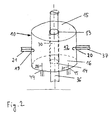
- the measuring arrangement comprises an applicator 10, which has metallic walls 11, 15, 16 for forming a resonator cavity 12.
- the metallic walls 11, 15, 16 can also be formed on a support by a metallization, ie a metallic coating produced, for example, by vapor deposition.
- a first sample passage opening 13 in a first end face 15 and a second sample passage opening 14 in a second end face 16 of the applicator 10 are provided.
- the passage openings 13, 14 are used to pass a product 36 through the resonator cavity 12 in the applicator 10.
- a guide tube 17 is provided from a low-loss dielectric.
- the resonator cavity 12 may be cylindrical, in particular circular cylindrical shaped. Such an embodiment is shown in FIG. However, the invention is not limited thereto. In particular, the resonator cavity 12 may also be rectangular or cuboid, as shown for example in FIG.
- the applicator 10 has two microwave connections 19, 20 with coupling devices 24, 25.
- Microwave coaxial cables 21, 37 are connected to the microwave ports 19, 20.
- the coaxial cables 21, 37 are formed by a uniform coaxial cable 38.
- the coaxial cable 38 and the cavity 12 together form an annular microwave resonator 27.
- Microwaves are generated by means of a generator 23 controlled by a control device 22 and passed by means of a coaxial line 18 via a connection 44 to a coupling device 26, through which the microwave field is coupled into the cavity 12.
- the length of the resonator coaxial cable 38 and the frequency of the microwave field generated by the generator 23 are tuned such that a standing resonant microwave field is formed in the resonator 27. As a rule, the resonance used for the measurement is fixed.
- Fig. 1 is a shielded resonator cavity 12 which is substantially closed except for the openings 13, 14 for the sample passage, wherein the openings for Probenein- or - prepare entry in or through the resonator hardly disturb the field profile.
- a half-wave 28a of the microwave electric field is formed in this example.
- the field profile in the resonator cavity can correspond, for example, to the E 010 resonance of a completely closed circular cylindrical cavity resonator.
- the field pattern in the resonator cavity may correspond to the H 101 resonance of a fully closed rectangular cavity resonator.
- the resonator coaxial cable 38 three half-waves 29a, 29b, 29c of the electric field propagate in the example shown in FIG. Overall, four mutually coupled half-waves 28a, 29a-c of the electric field thus form along the resonator 27. Since a significant portion of the microwave energy is stored in the unloaded resonator coaxial cable 38, the coupling of the sample to the field in the resonator cavity 12 is less than in a cavity resonator without resonator coaxial cable 38.
- the resonant microwave field interacts with the product in the interaction zone 30.
- a microwave signal modified by the interaction is coupled out of the cavity 12 and fed by means of a coaxial line 32 to an analyzer 33, the output signal of which is programmed by a corresponding evaluation device 34 is processed.
- Generator 23, analyzer 33, control device 22 and evaluation device 34 may be combined in a control unit 35.
- the decoupled signal is due to the interaction with the product in the interaction zone 30 is modified characteristically, for example in the form of a shift of the resonance frequency and a change in the width of the resonance curve.
- the presence of foreign bodies, in particular a solid foreign substance, in the product can also be derived from the decoupled signal.
- the measurement frequency is moved in the region of the measurement resonance in order to be able to determine two independent measurement parameters, for example the width of the measurement resonance and the resonance frequency.
- the control device 22 is preferably programmed accordingly.
- Control device 22 and evaluation device 34 may be formed by a computer.
- the determination of two independent parameters allows, for example, the determination of the product moisture irrespective of the product density, and / or the product density independent of the product moisture content.
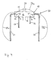
- the embodiment according to FIG. 3 relates to an open rectangular resonator cavity 12, in which, for example, a field corresponding to the H 101 resonance of a completely closed rectangular cavity resonator is formed.
- the resonator cavity 12 is opened so that flow over the separation point at most low wall currents.
- the resulting gap-shaped opening 39 can be used for sample introduction, in particular a flat, for example web-shaped product, but also one or more product strands.
- the gap-shaped opening 39 is provided with an externally idling parallel plate arrangement 40 ("choke") whose radial length is a quarter wavelength and which acts as a virtual short circuit at the separation point.
- the embodiment according to FIG. 3 illustrates that the applicator 10 does not have to have any separate connections 44, 45 or coupling devices 26, 31 for the lines 18, 32 for supplying or discharging the microwaves.
- the microwaves are in this example fed into the resonator coaxial cables 21, 37, for example using T-pieces 41, 42.
- the microwave resonator in this example is formed by the resonator cavity 12 and the resonator coaxial cables 21, 37 and 43.
- the resonator coaxial cables 21 and 37 are not connected to one another.
- the resonator 27 is therefore not a ring resonator, but a linear resonator.
- the length of the resonator coaxial cables 21, 37 and the dimensions of the resonator cavity are tuned such that an odd number of half-waves of the electric field, in the present example three half-waves 28a, 29a, 29b propagate via the resonator 27.
- This embodiment is particularly advantageous if ring closure of the resonator coaxial cables 21, 37 can not be achieved, for example, due to extensive, in particular flat, samples.
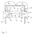
- a multiplicity of half-waves of the electric field in the present example two half-waves 28a, 28b, propagate in the preferably rectangular resonator cavity 12.
- Sample supply means 13a, 14a, 17a and 13b, 14b, 17b are provided for separate sample introduction in both half-waves in the region of the intensity maximum.
- Such an applicator 10 can be used, for example, in a two-line machine, more generally in a multi-line machine become. Overall, an even number of half-waves expands in the resonator 27 expediently.
- two half-waves 29a, 29b propagate in the resonator coaxial cable 38 and a total of four half-waves 28a, 28b, 29a, 29b in the resonator 27.
- the resonator cavity 12 in the embodiments of Figs. 1-5 is substantially free of dielectric material, i. the resonator cavity 12 is filled with air. This is advantageous because an additional dielectric material brings with it an additional temperature dependence, which can adversely affect the measurement result.
- the use of a homogeneous dielectric filling for the resonator cavity 12 is not excluded, for example, to achieve a reduction in the dimensions of the applicator 10.
- the measurement frequency generated by the generator 23 is preferably in the range of 100 MHz to 10 GHz, more preferably in the range of 1 to 5 GHz.
Landscapes
- Physics & Mathematics (AREA)
- Electromagnetism (AREA)
- Health & Medical Sciences (AREA)
- Life Sciences & Earth Sciences (AREA)
- Chemical & Material Sciences (AREA)
- Analytical Chemistry (AREA)
- Biochemistry (AREA)
- General Health & Medical Sciences (AREA)
- General Physics & Mathematics (AREA)
- Immunology (AREA)
- Pathology (AREA)
- Measurement Of Resistance Or Impedance (AREA)
Priority Applications (2)
| Application Number | Priority Date | Filing Date | Title |
|---|---|---|---|
| EP20060018052 EP1895290B1 (fr) | 2006-08-30 | 2006-08-30 | Dispositif à micro-ondes destiné à déterminer au moins une grandeur de mesure sur un produit |
| DE200650004072 DE502006004072D1 (de) | 2006-08-30 | 2006-08-30 | Mikrowellenmessvorrichtung zur Bestimmung mindestens einer Messgrösse an einem Produkt |
Applications Claiming Priority (1)
| Application Number | Priority Date | Filing Date | Title |
|---|---|---|---|
| EP20060018052 EP1895290B1 (fr) | 2006-08-30 | 2006-08-30 | Dispositif à micro-ondes destiné à déterminer au moins une grandeur de mesure sur un produit |
Publications (2)
| Publication Number | Publication Date |
|---|---|
| EP1895290A1 true EP1895290A1 (fr) | 2008-03-05 |
| EP1895290B1 EP1895290B1 (fr) | 2009-06-24 |
Family
ID=37810631
Family Applications (1)
| Application Number | Title | Priority Date | Filing Date |
|---|---|---|---|
| EP20060018052 Active EP1895290B1 (fr) | 2006-08-30 | 2006-08-30 | Dispositif à micro-ondes destiné à déterminer au moins une grandeur de mesure sur un produit |
Country Status (2)
| Country | Link |
|---|---|
| EP (1) | EP1895290B1 (fr) |
| DE (1) | DE502006004072D1 (fr) |
Cited By (4)
| Publication number | Priority date | Publication date | Assignee | Title |
|---|---|---|---|---|
| GB2445108B (en) * | 2006-12-22 | 2011-03-16 | Truetzschler Gmbh & Co Kg | Microwave resonator for or on a textile machine, especially a card, draw frame, combing machine or the like |
| WO2013164627A1 (fr) * | 2012-05-02 | 2013-11-07 | Heriot-Watt University | Capteur avec cavité à hyperfréquence |
| EP2909623B1 (fr) * | 2012-10-22 | 2017-02-22 | M-Flow Technologies Ltd. | Cavité résonnante avec un tube pour l'échantillon et avec un élément remplissant la cavité, qui sont en matériau composite |
| CN108801598A (zh) * | 2018-06-27 | 2018-11-13 | 电子科技大学 | 基于染料光学敏化特性的光功率微波测试装置及方法 |
Citations (5)
| Publication number | Priority date | Publication date | Assignee | Title |
|---|---|---|---|---|
| US3286208A (en) | 1964-05-12 | 1966-11-15 | Kenneth E Niebuhr | R-f high power simulation |
| JPS59190641A (ja) | 1983-04-14 | 1984-10-29 | Nippon Denso Co Ltd | アルコ−ル含有率センサ |
| DE4004119A1 (de) * | 1990-02-10 | 1991-08-14 | Tews Elektronik Dipl Ing Manfr | Verfahren zur messung der feuchte eines messgutes mit hilfe von mikrowellen und vorrichtung zur durchfuehrung des verfahrens |
| DE19705260A1 (de) * | 1996-02-20 | 1997-08-21 | Hauni Maschinenbau Ag | Verfahren und Anordnung zum Erfassen mindestens einer Eigenschaft eines Stoffes |
| EP1564548A1 (fr) | 2004-02-12 | 2005-08-17 | AMS- Advanced Microwave Systems GmbH | Résonateur à hyperfréquence excité en modes plus hautes pour mésurer une propriété dielectrique d'un produit |
-
2006
- 2006-08-30 EP EP20060018052 patent/EP1895290B1/fr active Active
- 2006-08-30 DE DE200650004072 patent/DE502006004072D1/de active Active
Patent Citations (5)
| Publication number | Priority date | Publication date | Assignee | Title |
|---|---|---|---|---|
| US3286208A (en) | 1964-05-12 | 1966-11-15 | Kenneth E Niebuhr | R-f high power simulation |
| JPS59190641A (ja) | 1983-04-14 | 1984-10-29 | Nippon Denso Co Ltd | アルコ−ル含有率センサ |
| DE4004119A1 (de) * | 1990-02-10 | 1991-08-14 | Tews Elektronik Dipl Ing Manfr | Verfahren zur messung der feuchte eines messgutes mit hilfe von mikrowellen und vorrichtung zur durchfuehrung des verfahrens |
| DE19705260A1 (de) * | 1996-02-20 | 1997-08-21 | Hauni Maschinenbau Ag | Verfahren und Anordnung zum Erfassen mindestens einer Eigenschaft eines Stoffes |
| EP1564548A1 (fr) | 2004-02-12 | 2005-08-17 | AMS- Advanced Microwave Systems GmbH | Résonateur à hyperfréquence excité en modes plus hautes pour mésurer une propriété dielectrique d'un produit |
Non-Patent Citations (2)
| Title |
|---|
| MIZIER M O: "MESURES D'HUMIDITE: POURQUOI PAS LES HYPERFREQUENCES?", MESURES REGULATION AUTOMATISME, CFE. PARIS, FR, vol. 50, no. 1, January 1985 (1985-01-01), pages 67 - 70, XP002057631, ISSN: 0755-219X * |
| R. KNÖCHEL: "Materialfeuchtemes- sung", 1997, EXPERT-VERLAG, article "Mikrowellenmessverfahren: Messprinzipien und Applikatorformen", pages: 146 |
Cited By (8)
| Publication number | Priority date | Publication date | Assignee | Title |
|---|---|---|---|---|
| GB2445108B (en) * | 2006-12-22 | 2011-03-16 | Truetzschler Gmbh & Co Kg | Microwave resonator for or on a textile machine, especially a card, draw frame, combing machine or the like |
| WO2013164627A1 (fr) * | 2012-05-02 | 2013-11-07 | Heriot-Watt University | Capteur avec cavité à hyperfréquence |
| CN104704351A (zh) * | 2012-05-02 | 2015-06-10 | 赫瑞-瓦特大学 | 微波空腔传感器 |
| CN104704351B (zh) * | 2012-05-02 | 2018-07-10 | 赫瑞-瓦特大学 | 微波空腔传感器 |
| US10024806B2 (en) | 2012-05-02 | 2018-07-17 | Heriot-Watt University | Microwave cavity sensor |
| EP2909623B1 (fr) * | 2012-10-22 | 2017-02-22 | M-Flow Technologies Ltd. | Cavité résonnante avec un tube pour l'échantillon et avec un élément remplissant la cavité, qui sont en matériau composite |
| US10386281B2 (en) | 2012-10-22 | 2019-08-20 | M-Flow Technologies Ltd | Fluid sensor |
| CN108801598A (zh) * | 2018-06-27 | 2018-11-13 | 电子科技大学 | 基于染料光学敏化特性的光功率微波测试装置及方法 |
Also Published As
| Publication number | Publication date |
|---|---|
| EP1895290B1 (fr) | 2009-06-24 |
| DE502006004072D1 (de) | 2009-08-06 |
Similar Documents
| Publication | Publication Date | Title |
|---|---|---|
| EP1855104B1 (fr) | Procédé de mesure à micro ondes destiné à la détermination d'une grandeur de mesure sur un produit | |
| EP1241469B1 (fr) | Dispositif résonateur hyperfréquence pour des mesures sur du tabac | |
| DE19705260B4 (de) | Anordnung zum Erfassen mindestens einer dielektrischen Eigenschaft eines Stoffes | |
| DE102006017438B4 (de) | Resonator für Magnetresonanzanwendungen | |
| EP1221608B1 (fr) | Méthode pour tester un matériau de production dans un champ de micro-ondes | |
| DE202005001756U1 (de) | Mikrowellensensor zur Messung einer dielektrischen Eigenschaft eines Produkts | |
| DE3317215C2 (fr) | ||
| DE19925468A1 (de) | Streufeldsonde | |
| EP0753755A2 (fr) | Dispositif de mesure de la constante diélectrique complexe du tabac | |
| EP2572594A2 (fr) | Boîtier de résonateur pour micro-ondes passé par un tronçon de matière pour déterminer des attributs du tronçon de matière | |
| EP1895290B1 (fr) | Dispositif à micro-ondes destiné à déterminer au moins une grandeur de mesure sur un produit | |
| EP2069777B1 (fr) | Dispositif pour une machine textile destiné à mesurer le poids spécifique à la longueur et/ou l'humidité d'une quantité de fibre défilante en écheveau | |
| EP0717269A2 (fr) | Procédé et dispositif pour la mesure sans contact du débit massique dans un transport biphasique et pneumatique en utilisant des microondes | |
| DE102006034884A1 (de) | Messgerät zur Bestimmung der elektromagnetischen Eigenschaften eines Fluids | |
| EP2146198B1 (fr) | Procédé et dispositif de mesure du chargement d'un faisceau de l'industrie de traitement du tabac à l'aide d'une quantité de matière | |
| DE3711184A1 (de) | Vorrichtung zur einbringung von mikrowellenenergie mit einem offenen mikrowellenleiter | |
| WO2011061283A1 (fr) | Dispositif et procédé pour générer un plasma au moyen d'un résonateur à ondes progressives | |
| DE602004006154T2 (de) | Sensor und gesamtvorrichtung zur hydrometrischen messung | |
| DE102018127924A1 (de) | Vorrichtung und Verfahren zur Messung von Materialeigenschaften eines Tabakstrangs | |
| EP1371979B1 (fr) | Dispositif à micro-ondes pour tester la qualité des matériaux en forme de cordon | |
| DE102009024203B4 (de) | Mikrowellensensor und Verfahren zur Bestimmung dielektrischer Materialeigenschaften | |
| EP0943913A2 (fr) | Procédé et appareil pour déterminer la composition des particules solides fluidisables | |
| DE102023117163A1 (de) | Gerät zur messung mindestens einer elektromagnetischen eigenschaft einer materialprobe | |
| EP1564548A1 (fr) | Résonateur à hyperfréquence excité en modes plus hautes pour mésurer une propriété dielectrique d'un produit | |
| EP2998723B1 (fr) | Dispositif de mesure a micro-ondes d'une barre, procede et utilisation |
Legal Events
| Date | Code | Title | Description |
|---|---|---|---|
| PUAI | Public reference made under article 153(3) epc to a published international application that has entered the european phase |
Free format text: ORIGINAL CODE: 0009012 |
|
| AK | Designated contracting states |
Kind code of ref document: A1 Designated state(s): AT BE BG CH CY CZ DE DK EE ES FI FR GB GR HU IE IS IT LI LT LU LV MC NL PL PT RO SE SI SK TR |
|
| AX | Request for extension of the european patent |
Extension state: AL BA HR MK YU |
|
| 17P | Request for examination filed |
Effective date: 20080619 |
|
| AKX | Designation fees paid |
Designated state(s): DE FR GB IT |
|
| GRAP | Despatch of communication of intention to grant a patent |
Free format text: ORIGINAL CODE: EPIDOSNIGR1 |
|
| GRAS | Grant fee paid |
Free format text: ORIGINAL CODE: EPIDOSNIGR3 |
|
| GRAA | (expected) grant |
Free format text: ORIGINAL CODE: 0009210 |
|
| AK | Designated contracting states |
Kind code of ref document: B1 Designated state(s): DE FR GB IT |
|
| REG | Reference to a national code |
Ref country code: GB Ref legal event code: FG4D Free format text: NOT ENGLISH |
|
| REF | Corresponds to: |
Ref document number: 502006004072 Country of ref document: DE Date of ref document: 20090806 Kind code of ref document: P |
|
| PLBE | No opposition filed within time limit |
Free format text: ORIGINAL CODE: 0009261 |
|
| STAA | Information on the status of an ep patent application or granted ep patent |
Free format text: STATUS: NO OPPOSITION FILED WITHIN TIME LIMIT |
|
| 26N | No opposition filed |
Effective date: 20100325 |
|
| PG25 | Lapsed in a contracting state [announced via postgrant information from national office to epo] |
Ref country code: IT Free format text: LAPSE BECAUSE OF FAILURE TO SUBMIT A TRANSLATION OF THE DESCRIPTION OR TO PAY THE FEE WITHIN THE PRESCRIBED TIME-LIMIT Effective date: 20090624 |
|
| REG | Reference to a national code |
Ref country code: FR Ref legal event code: PLFP Year of fee payment: 11 |
|
| REG | Reference to a national code |
Ref country code: FR Ref legal event code: PLFP Year of fee payment: 12 |
|
| PGFP | Annual fee paid to national office [announced via postgrant information from national office to epo] |
Ref country code: FR Payment date: 20170822 Year of fee payment: 12 |
|
| PG25 | Lapsed in a contracting state [announced via postgrant information from national office to epo] |
Ref country code: FR Free format text: LAPSE BECAUSE OF NON-PAYMENT OF DUE FEES Effective date: 20180831 |
|
| PGFP | Annual fee paid to national office [announced via postgrant information from national office to epo] |
Ref country code: GB Payment date: 20230824 Year of fee payment: 18 |
|
| PGFP | Annual fee paid to national office [announced via postgrant information from national office to epo] |
Ref country code: DE Payment date: 20230815 Year of fee payment: 18 |